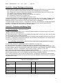
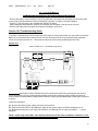
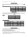
1
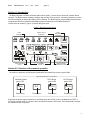
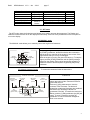
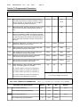
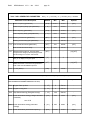
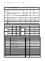
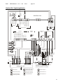
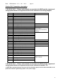
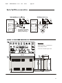
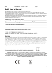
Be28
OEM's Manual
V1.0 - Jan. - 2013
page 1
Be28 3-Phase ATS Controller OEM’s Manual
The information in this document is subject to change without notice.
No part of this document may be copied or reproduced in any form or any means without the prior written
consent of Bernini Design. Bernini Design assumes no responsibility for any errors which may appear in this
instruction manual or in the wiring diagrams. Although Bernini Design has taken all possible steps to ensure that
the User Manual is complete, bug free and up-to-date, we accept that errors may occur.
__________________________________________________________________________
Customer Support BERNINI DESIGN SRL ITALY
e-mail: [email protected]
Mobile 1: ++39 335 7077148. Mobile 2:++40 721 241 361
Warranty
Bernini Design SRL (hereinafter "BD") warrants that Be28 shall be free from defect in material or workmanship
for a period of 3 years from the BD delivery date. BD shall, at its option, repair or replace the product without
charge. BD shall return the Be28 to the buyer with the Default parameters at no extra charge. The buyer shall
furnish sufficient information on any alleged defects in the product, so as to enable BD to determine their cause
and existence. If the Be28 is not defective, or the product is defective for reason other than covered by this
warranty, the buyer will be charged accordingly. This warranty shall not apply if the Be28 has not been used in
accordance with the User Manual and other operating instruction, particularly if any defects are caused by
misuse, improper repair attempts, negligence in use or handling.
This purchase is non-refundable.
This equipment complies with the EMC protection requirements
WARNING!! High voltage is present inside the Be28. To avoid electric-shock hazard, operating
personnel must not remove the protective cover. The Be28 can start the engine at anytime. Do not work
on equipment, which is controlled by the Be28. When servicing the engine, disconnect the battery and
battery charger. We recommend that warning signs be placed on equipment indicating the above.
!! W A R N I N G !! Relays and solenoids connected to the Be28 must be suppressed
using flywheel diodes or suppression devices as indicated in section 15.0.
1
Be28
OEM's Manual
V1.0 - Jan. - 2013
page 2
Alphabetic index
Alarms .............................. 4.10, 8.0
Alarm output control ....... 7.09, [39]
Alarm inputs .................... 7.06, 8.0
Automatic......................... 2.3
Battery, Alarms ................ 4.10 [Er.13]
Calibration ........................ 9.0
Characteristics ................. 11.0
Contactor ......................... 2.21, 15.0
Connectors, Plugs........... 16.0
Connections list .............. 16.0
Current Transformer ....... 7.02B [P.18]
Cooling down time .......... 7.03 [P.24]
Manual mode ...................... 2.2
Outputs (programmable) ... 7.09
Operational modes ............. 2.0
Overload ............................. 4.10 [Er.05]
Overload (external)............. 7.07 [20][21]
Over Frequency .................. 4.10 [Er.01]
Over Voltage HI-U ............... 4.10 [HI-U]
Parameters ......................... 7.0
Parameters reading ............ 6.30
Program, Programming ..... 6.0
Power Supply ..................... 11.0
Push buttons ...................... 2.0, 2.2
Defaults ............................ 6.20
Dimensions ...................... 18.0
Display ............................. 3.0
Display Messages ........... 4.10, 4.20
Settings (Parameters) ........ 7.0
Single Phase operation ...... 13.10
Specifications ..................... 11.0
Software upgrade ............... 12.0
Er.0.. Error codes ............ 4.10
[FAIL] Memory error ........ 4.10 [FAIL]
Emergency input ............. 4.10 [Er.08]
Events .............................. 13.30
Terminal description .......... 16.0
Test, Remote Test ............. 7.07 [10] [11]
Test mode .......................... 2.4
Transformer, Current ......... 7.02B [P.18]
Troubleshooting ................. 10.0
Front Panel ...................... 1.0 Figure 1
Frequency ........................ 7.02A [P.11][P.12]
Generator Voltage ........... 7.02 [P.9] [P.10]
Generator Frequency ...... 7.02 [P.11] [P.12]
Generator Failure E04 ..... 7.02B [P.15]
Hi-U, Over Voltage ........... 7.02A [P.10]
Under Voltage Lo-U ............ 7.02A [P.09]
Under Frequency ................ 7.02A [P.11]
Voltage measurements ...... 3.0
Warm-Up time ..................... 7.03 [P.23]
Wiring diagram ................... 15.0
Inputs (Programmable) ... 7.06, 7.07
LED, LEDs ........................ 5.0
Lamp Test ........................ 5.1
Lo-U, Under Voltage ........ 7.02A [P.09]
Low Battery voltage ........ 4.10,[Er.13]
Log Events ....................... 13.30
Mains Failure ................... 7.01 [P.01]
Mains Restore .................. 7.01 [P.02]
Mains Simulation ............. 7.07 [15]
Measurements ................. 3.0
Memory clear, restore ..... 9.3
Memory Events ................ 13.30
Messages (Display) ......... 4.0
2
Be28
OEM's Manual
V1.0 - Jan. - 2013
page 3
BE28 OEM's Manual - Contents
1.0 Introduction ...................................................... page 4
2.0 Selection of the mode of operation ............... page 4
2.1 OFF mode ........................................................ page 5
2.2 MANUAL mode ................................................ page 5
2.3 AUTO mode ..................................................... page 6
2.4 TEST mode ...................................................... page 6
3.0 DISPLAY measurements ................................. page 6
4.0 DISPLAY messages ......................................... page 7
5.0 LED indicators ................................................. page 8
6.0 PROGRAMMING & READING parameters ..... page 8
6.10 Enter the Programming Mode ....................... page 8
6.11 Enter the password ....................................... page 9
6.12 Programming ................................................ page 9
6.13 Saving ........................................................... page 9
6.14 Exit without saving ........................................ page 9
6.20 Re-programming default settings ................. page 9
6.30 Reading the parameters ............................... page 10
6.40 Activating the password ................................ page 10
6.50 Changing the password ................................ page 10
6.60 Removing the password ............................... page 10
7.0 Programmable Parameter ............................... page 11
Table 7.01 Mains Failure Control ......................... page 11
Table 7.02A-B Generator Parameters ................ page 12
Table 7.03 Engine Parameters ............................ page 12
Table 7.04 Alarms Options .................................. page 13
Table 7.05 Miscellaneous .................................... page 13
Table 7.06 Programmable Inputs ........................ page 13
Table 7.07 Input Options .................................... page 13
Table 7.08 Programmable Outputs ..................... page 14
Table 7.09 Outputs Options ................................ page 14
8.0 Alarms, Warnings & Shutdowns .................... page 15
9.0 Calibration and Memory Reset ...................... page 15
10.0 Troubleshooting guide ................................. page 16
11.0 General Specifications ................................. page 18
12.0 Software Upgrades & Revisions ................. page 18
13.0 Application Notes ........................................ page 19
14.0 Panel builder Notes ...................................... page 19
15.0 Typical application ........................................ page 20
16.0 Connections description .............................. page 21
17.0 Wiring recommendations ............................ page 22
18.0 Dimensions and rear view ........................... page 22
3
Be28
OEM's Manual
V1.0 - Jan. - 2013
page 4
Section 1.0 Introduction
The Be28 integrates a 3-Phase Automatic Mains Failure (A.M.F.) module and an Automatic Transfer Switch
controller. The Be28 monitors 3 phases (voltages and currents) of the generator. It provides indication by means
of LEDs and Display for Alarms and status of the contactors. The Be28 features programmable parameters and
complies with NFPA110 CAN/CSA-C282-M89 regulations. Be28 features a RS485 interface for
remote control & monitoring. Figure 1 presents the panel layout.
Figure 1: Be28 Front Panel layout
Alarm
acknowledge
pushbutton
Display control
& indicators
Alarm
messages
F10
A
V
Frequency
Engine
Program.
F8
F1
F2
Manual Generator
Control
F9
F3
F4
F5
F6
F7
Operating Mode
pushbuttons & LEDs
Contactors
Control
Section 2.0 Selection of the mode of operation
The modes of operations are selected by pushbuttons and indicated by means of green LEDs:
Operating Modes Pusbuttons
Operating Modes
MANUAL Mode
green LED
MAN
Pushbutton
TEST Mode
green LED
AUTO Mode
green LED
OFF
OFF
TEST
TEST
AUTO
AUTO
Pushbutton
Pushbutton
Pushbutton
Every time the power supply is switched on, the Be28 enters the “AUTO” mode, if the Be28 was in TEST or
AUTO prior to power down. In the other cases, the Be28 will enter the OFF mode. The following table indicates
the available modes of operation.
4
Be28
OEM's Manual
V1.0 - Jan. - 2013
Mode of operation
OFF
MANUAL
AUTO
TEST
PROGRAMMING
CALIBRATION
TROUBLESHOOTING
page 5
Pushbutton
[ OFF ]
[ MAN ]
[AUTO]
[TEST]
Combined
action of
buttons
Indication
Dot on display
Green LED on the button
Green LED on the button
Green LED on the button
The display shows [ProG]
The display shows [-CAL]
See section 10.0
Section
2.1
2.2
2.3
2.4
6.0
9.0
2.1 OFF mode
The OFF mode clears the fault alarms and allows you to read or program the parameters. The Display and
LEDs are turned off and a dot on the display will blink slowly. Push one of the pushbuttons on the front panel to
turn on the display.
2.2 MANUAL mode
The MANUAL mode allows you to manually control the engine and Contactors.
Instructions
Push the [MAN] pushbutton to select the MANUAL mode. Push
the [START] pushbutton: the Be28 maintains the command to
start the engine to controller of the engine for one minute. If the
engine fails to start you can try to start again.
When the engine is running, the green LED turns on. To stop the
engine, push the [STOP] pushbutton until the [StOP] message
appears on the display. If the engine has already stopped, it is
possible to reset the STOP sequence by pressing the [STOP]
pushbutton.
Manual Engine Control
Engine Running
green LED
START
Pushbutton
STOP
Pushbutton
2.21 Manual Contactor Control
To control the contactors follow the instructions:
Contactors Control Panel
Generator
Presence LED
(Green)
KG-closed
indicator
(Green)
KM-closed
indicator
(Green)
KG
Instructions
Mains
Presence LED
(Green)
KM
KM
Pushbutton
(push to close)
KG
Pushbutton
(push to close)
[ O ]Pushbutton
(push to open)
Select the MANUAL mode, start the engine (see
above) and wait until the ‘Generator Presence’
green LED turns on.
Push the [I] (KG) pushbuttons to close the
contactor of the Generator. The alarms of
Under/Over voltage and frequency are enabled if
the Be28 works according to NFPA-110
(parameter P23=ON). To transfer the load to the
Mains, push the [I] (KM) pushbutton (the [KG] will
open). To open a contactor, push the [O]
pushbutton. In manual mode the changeover
timer is one second.
5
Be28
OEM's Manual
V1.0 - Jan. - 2013
page 6
2.3 AUTO mode
Push the [AUTO] pushbutton until the green LED will illuminate. The message [Auto] will appear for a
second on display. The engine starts when the Be28 detects a Mains failure. The contactor of the MAINS
(KM) opens after the [P.0] (Breaker) timing. Then the timer [P.01] takes palce to delay the start of the
engine. Once started, after the warm-up ([P23]) time (Voltage and Frequency must be within the settings),
the contactor of the GENERATOR (KG) will close. If the Mains restores, after the [P.02] the KG will open.
The KM will close after a programmable changeover timing ([P.3]). The Engine will stop after a cooling
down time ([P24]). If the engine shuts down, the KM closes independently of the Mains status if the [P.23] is
[ON] (NFPA-110 mode), otherwise the KM will close only if the Mains is within the programmed settings. In
AUTO mode, the Be28 can start and stop the engine according to programmed inputs (see Table 7.06 and
7.07).
Note: the BE28 turns on the alarm [Er.11] (Fail to start) if the engine does not start within 8 minutes after the
engine start request.
2.4 TEST mode
Push the [TEST] pushbutton until the green LED illuminates; the display will indicate the message [Test] for a
second. The Be28 starts the engine and transfers the load to the generator if the [P.17] is [on]. To stop the
engine, select the AUTO mode (if the Mains is present) or select the OFF mode. If you push the [STOP]
pushbutton when the Be28 is in AUTO or TEST, the [Er.09] will energise. To clear the alarm, select the OFF
mode (section 8.0).
Section 3.0 Display measurements
The Be28 features a 4 Digit display, two pushbuttons and 5 yellow LEDs as indicated below.
Frequency-Speed
Display menu
Vac-Generator-Mains
Display menu
Generator-Current
Display menu
[ F8 ] control
Pushbutton
A
V
Frequency
Engine
F8
Display-Vbattery
Program
F9
Programming
Display menu
[ F9 ]
Display control
Pushbutton
4Digit Display
Use [←F8] and [F9→] to select a menu. Use [ACK-F10] (see the layout in section 1.0) to display the name of
the parameter. The OFF mode shuts down the display and turns on the dot on the right side of it. Push a button
to turn on the panel. The following table lists the functions of the display.
6
Be28
OEM's Manual
V1.0 - Jan. - 2013
page 7
Display Function
Current of the Generator
(0 up to 999A). Phases L1L2 & L3.
Display indications (*)
[A XXX][- XXX] [_XXX]
Pushbutton(s)
[A -G]
[ACK-F10]
Voltage of the Generator
(60V up to 600V). Phases
L1-L2 & L3.
[GXXX] [-XXX] [_XXX]
[←F8] or [F9→]
[U -G]
[ACK-F10]
[ nXXX ] (V R-S)
[ -XXX ] (V S-T)
[ _XXX ] (V T-R)
[←F8] or [F9→]
[U -n]
[ACK-F10]
[GXXX] Hz
[←F8] or [F9→]
[H - G]
[ACK-F10]
[nXXX] Hz
[←F8] or [F9→]
Voltage of the Mains
(60V up to 600V). If the
Mains is simulated (see
option [15] in table 7.07)
the display will show the
message [n-on]
Generator Frequency
(20Hz up to 70Hz)
Mains Frequency
(20Hz up to 70Hz)
[H - n]
[SPd]
[bXX.X] Vdc
Battery Voltage
(5,5 Vdc up to 36Vdc)
[batt]
Voltage of the Charger
Alternator (5,5 -36Vdc)
[cXX.X] Vdc
[←F8] or [F9→]
Menu & Led indicator
Aac
Yellow
menu
Vac
menu
Yellow
Hz/RPM
menu
Yellow
Engine
Yellow
[ACK-F10]
[ACK-F10]
[←F8] or [F9→]
[ACK-F10]
[←F8] or [F9→]
(*)NOTE: X indicates a numerical digit, if the measurement is out of range, the display will indicate [- - - -]
Section 4.0 Display messages
The Be28 shows alarms (table 4.10) and messages (table 4.20). The presence of an alarm is indicated by the
blinking message [ ALAr.]. Push the [→F9] pushbuttons to display the alarm. Push the [←F8] pushbutton to
display additional information about alarm (section 8.0).
Table 4.10-A: Alarm messages (these messages are recorded in the ‘Log Events’ also. See 13.30)
Display
Message
[Er.01]
[Er.04]
[Er.05]
[Er.06]
Description of the Alarm
Over Frequency Shutdown
Alternator Failure Shutdown
Overload warning
Under Frequency Shutdown
Display
Message
[Er.08]
[Er.09]
[Er.11]
[Er. 13]
Description of the Alarm
Emergency Shutdown
Emergency Shutdown from the Front Panel
The engine failed to start
Battery Voltage Warning. Push [←F8] to display
7
Be28
OEM's Manual
V1.0 - Jan. - 2013
page 8
Table 4.10-B: Alarm messages (these messages are recorded in the ‘Log Events’ also. See 13.30)
Display
Message
Description of the Alarm
Display
Message
Description of the Alarm
[Hi-C]
Over Current Shutdown or Warning
[InP.1]
Input 1 Shutdown / Warning (see 7.07)
[Hi-U]
Over Voltage Shutdown
[InP.2]
Input 2 Shutdown / Warning (see 7.07)
[Lo-U]
Under Voltage Shutdown
[InP.3]
Input 3 Shutdown / Warning (see 7.07)
[FAIL]
There is an internal failure or memory
error in the Be28 controller (see 9.3)
[InP.4]
Input 4 Shutdown / Warning (see 7.07)
4.20 Operational messages
Message
Description
Message
Description
[....]
The Be28 is starting the engine
[ProG]
Program mode
[n-on]
MAINS Simulated. A programmable input
simulates the presence of the Mains (see
option [10] in the table 7.07).
The Be28 is stopping the engine
[-CAL]
Calibration mode
[----]
The measurement is not available.
[StoP]
[AUTO]
[- P0]
[- P2]
The message appears for one second when
you enter the AUTO mode
This message appears when the Be28 counts
the mains breaker timing (*)
This message appears when the Be28 counts
the mains restore timing (*)
[tESt]
Test mode
[MAN]
The message appears for one second
when you enter the MAN mode
[- P1]
This message appears when the Be28
counts the mains failure timing (*)
(*) Push [ACK-F10] to display the status of the count
down of the timer.
Section 5.0 LED indicators
To test the LEDs and DISPLAY push the [OFF] pushbutton; the display turns off. Push and hold the [←F8]
and [F9→] pushbuttons simultaneously. The LEDs and DISPLAYs remain tuned on as long as the pushbuttons
are pressed and held together.
Section 6.0 Programming / Reading Parameters
To enter the Programming Mode, use the following instructions. Sections 6.40, 6.50 and 6.60 indicate how to
use the password.
6.10 Enter the Programming Mode
1) - Provide a voltage battery supply over 11.5V. Push the [OFF] pushbutton to enter the OFF mode; the LEDs
and display turn OFF and a dot on the right side of the display will start to blink.
2) - Push and hold the [F9→] and [ACK-F10] pushbuttons simultaneously, for about 5 seconds, until the yellow
Led [h/Prog.] starts to blink. When the display indicates [ProG], release the buttons.
3) - If the Be28 is password protected (*), the messages [PASS] and [42.42] will appear in sequence; you are
required to follow the instructions of Table 6.11. If the Be28 is not password protected, the parameter [P.0] will
be displayed and the Be28 is ready for programming (section 6.12, step-2).
(*) Note: the password consists of 2 groups of digits ranging from 0 to 99. Example: [12.34]; 12 is the 2-digit code on
the left, and 34 is the 2-digit code on the right.
8
Be28
OEM's Manual
V1.0 - Jan. - 2013
page 9
TABLE 6.11: Enter the PASSWORD
1) - Push [TEST] or [AUTO] in order to choose the proper code (between 00 and 99, except the code42).
2) - Push [F9] to select the 2 digits on the right side.
3) - Push [TEST] or [AUTO] in order to choose the proper code (between 00 and 99, except the code 42).
4) - Push [ACK-F10] to confirm the password; if the password is ok, the Be28 will indicate [P.0] and the unit is ready
for programming. If the password is wrong, the display will indicate [4242] and you are required to insert a proper
password.
If you loose the password, the unit must be returned for service.
6.12 Programming
1) - Enter the Programming mode (see section 6.10).
2) - Press the [←F8] or [F9→] pushbutton to select a parameter (see the list in section 7.0).
3) - To adjust the parameter, press [START-F1] and [TEST ↑] (or [AUTO ↓]) simultaneously.
(example: [P.10] = [500]; the Overvoltage limit is set to 500Volt. If you want to set 450, push and hold
[START-F1] and [AUTO ↓] until the display will indicate 450 )
4) - To adjust the sub-parameters (example the bypass time of Overvoltage), press [STOP-F2] and [TEST ↑]
(or [AUTO ↓]) simultaneously (example: default of the sub-parameter [P.10] is [2'']; you can program it to 10
seconds)
5) - Press the [←F8] or [F9→] pushbutton to select another parameter.
6) - Follow the instructions of section 6.13 or 6.14 according to your needs.
6.13 Saving
Press and hold the [ACK-F10] and [F9→] pushbuttons simultaneously until the [SAVE] message appears
(approximately 5 seconds); the Be28 saves the settings and will enter the OFF mode. After that, you can select
an operational mode (section 2.0).
Note: if the memory fails, the message [FAIL] will appear. Try again to save or remove the power supply. If the
message persists, the Be28 is damaged and should be returned to Bernini Design for repair.
6.14 Exit without Saving
Press the [OFF] pushbutton to enter the OFF mode without saving the parameters. You can select an
operational mode as indicated in section 2.0.
6.20 Re-programming Default settings
The parameters of the Be28 are factory programmed with default settings (section 7.0). To restore them, enter
the Programming Mode (section 6.10). When the message [P.0] appears, follow the instructions:
1) - Press and hold the [←F8] and [F9→] pushbuttons simultaneously until the display blinks twice. Select the
option 2A or 2B according to your needs.
2A) - Press the [OFF] pushbutton to exit the procedure without saving the parameters.
2B) - Press and hold the [ACK-F10] and [F9→] pushbuttons simultaneously until the [SAVE] message appears
(approximately 5 seconds); the Be28 saves the Defaults and the display will indicate [P0]. Push the [OFF]
pushbutton in order to enter the OFF mode.
9
Be28
OEM's Manual
V1.0 - Jan. - 2013
page 10
6.30 Reading the parameters
To read the setting of the parameters, follow the instructions:
1) - Press the [OFF] pushbutton until the LEDs and display turn OFF.
2) - Push the [←F8] or [F9→] pushbutton to select a parameter (section 7.0).
3) - Push [START-F1] to display the setting of the parameter (example: [P.10] = [450]; the Overvoltage limit is
set to 450Volt).
4) - Push [STOP-F2] to display the setting of the sub-parameter (example: [P.10] = [2'']. The timing delay of
Overvoltage is set to 2 seconds).
5) - Push the [←F8] or [F9→] pushbutton to select another parameter.
NOTE: if the pushbuttons remain inoperative for more than 5 minutes, the Be28 enters the OFF mode.
6.40 Activating the password
1) - Enter the programming mode as indicated in section 6.10.
2) - When the display shows [P.0], push the [ACK-F10] pushbutton for about 10 seconds until the display shows
[PP.PP]. When the display indicates [4242], release the button. The two digits on the right will blink.
3) - Push [TEST] or [AUTO] in order to choose a code.
4) - Push [←F8] to select the 2 digits on the left side. Repeat step 3) in order to choose a code
5) - Press the [OFF] pushbutton if you want to exit the procedure without activating the password.
6) - Press and hold the [ACK-F10] and [F9→] pushbuttons simultaneously until the [SAVE] message appears ;
the Be28 saves the password and remains in PROGRAM mode. To exit, push the OFF pushbutton. You can
change the password when you want as indicated in the section 6.50.
6.50 Changing the password
1) - Enter the programming as indicated in section 6.10 and table 6.11. When the display indicates the
parameter [P.0], push and hold the [ACK-F10] pushbutton for about 10 seconds until the message [PP.PP] and
[4242] will appear. The two digits on the left side of the display will blink.
2) - Push [TEST] or [AUTO] in order to choose a code.
3) - Push [←F8] to select the 2 digits on the right side. Repeat step 3) in order to choose a code
4) - Press the [OFF] pushbutton if you want to exit the procedure without activating the password.
5) - Press and hold the [ACK-F10] and [F9→] pushbuttons simultaneously until the [SAVE] message appears
(approximately 2 seconds); the Be28 saves the password and remains in PROGRAM mode. To exit, push the
OFF pushbutton.
6.60 Removing the password
1) - Enter the programming mode as indicated in section 6.10 part 3 (you are required to use the old password).
2) - When the display indicates the parameter [P.0], push and hold the [ACK-F10] pushbutton, for about 10
seconds until the display will indicate in sequence [PP.PP] and [4242]. The two digits on the right side will start
to blink. The code [4242] disables the use of the password. Follow step 3 of 4 according to your needs.
3) - Press the [OFF] pushbutton if you do not want to remove the password (you exit the procedure).
4) - Press and hold the [ACK-F10] and [F9→] pushbuttons simultaneously until the [SAVE] message appears
(approximately 2 seconds); the Be28 saves the code [4242] that disables the password. The Be28 remains in
PROGRAM mode. To exit, push the OFF pushbutton.
10
Be28
OEM's Manual
V1.0 - Jan. - 2013
page 11
Section 7.0 Programmable Parameters
Table 7.01 - Mains Failure Control
Note: [ xx " ] = seconds, [ xx ' ] = minutes, [xxh ] = hours
Parameter Code & Description
P.0
Mains Breaker control. If the Mains Failure persists for
Default
Min
Max
Options
[ 5’’]
0
59
-
more than [P.0] (seconds or minutes), the Mains contactor
will open and the [P.1] timer will start to count. The Mains
contactor will close only after the [P.2] timing.
P.1
Mains Failure time. After the [P.0] timing (see above), the
mins
[ 5’’]
0
23h
-
[ 5’’]
0
23h
-
[ 2’’]
0.1secs
15.0secs
-
[320]
60V
998V
[500]
60V
998V
[47.0]
20.0Hz
70.0Hz
engine will start if the Mains Failure persists for the [P.1]
time.
P.2
Mains Restore time. The Be28 transfers the Load to the
Mains once the MAINS is stable for at least [P.2] (seconds,
minutes or hours) . During [P.2] , the engine will continue to
run ON-LOAD. After [P.2], the [P.20] timer will take place to
run the engine OFF-LOAD (the contactor of the generator
will open)
P.3
Contactors changeover. This timing introduces a delay
between the switching of the contactors.
P.4
Under voltage limit. If the Phase-to-Phase voltage falls
[oFF]
under this limit, the [P.0] timer will energise.
P.5
Over voltage limit. If the Phase-to-Phase voltage rises
[oFF]
above the limit, the [P.0] timer will energise.
P.6
Under Hz limit. If the Phase-to-Phase voltage falls
[oFF]
under the limit, the [P.0] timer will energise.
P.7
Over Hz limit. If the Phase-to-Phase voltage rises
[53.0]
20.0Hz
70.0Hz
[oFF]
above the limit, the [P.0] timer will energise.
P.8
Phase Selection. It allows 3-Phase or Single Phase
[0]
[0]
[3]
control. The following options are available:
[0] 3 Phase V Mains & 3 Phase V/C Generator (*)
-
[1] 3 Phase V Mains & 1 Phase V/C Generator (*)
[2] 1 Phase V Mains & 3 Phase V/C Generator (*)
[3] 1 Phase V Mains & 1 Phase V/C Generator (*)
(*) V/C means Voltages and Currents
See section 16.30 for details and connections
Table 7.02A - GENERATOR PARAMETERS
Parameter Code & Description
P.9
Note: [ xx " ] = seconds, [ xx ' ] = minutes, [ oFF ] = disabled
Default
Min
Max
Options
Under voltage (parameter)
[320]
60V
998V
[oFF]
Under voltage delay (sub-parameter)
[ 6" ]
1sec
15secs
-
[500]
60V
998V
[oFF]
[ 2" ]
1sec
15secs
-
P.10 Over voltage (parameter)
Over voltage delay (sub-parameter)
11
Be28
OEM's Manual
V1.0 - Jan. - 2013
Table 7.02B - GENERATOR PARAMETERS
page 12
Note: [ xx " ] = seconds, [ xx ' ] = minutes, [ oFF ] = disabled
Parameter Code & Description
Default
Min
Max
Options
[47.0]
20.0Hz
70.0Hz
[oFF]
[ 6'' ]
1sec
15secs
-
[53.0]
20.0Hz
70.0Hz
[oFF]
[ 1" ]
1sec
15secs
-
[oFF]
10A
2000A
[oFF]
[ 1" ]
1sec
15mins
-
P.14 Over current shut down (parameter)
[oFF]
10A
2000A
[oFF]
Over current shut down delay
[ 1" ]
1sec
15mins
-
[oFF]
-
-
[on] [oFF]
[4]
2
4
-
[oFF]
-
-
[on] [oFF]
[500]
50A
1000A
-
P.11 Under Frequency (parameter)
Under Frequency delay (sub-parameter)
P.12 Over Frequency (parameter)
Over Frequency delay (sub-parameter)
P.13 Warning current limit (parameter)
Warning current delay (sub-parameter)
P.15 Alternator failure options. The alarm [E04]
energises if the voltage (or the frequency) is lower
than the setting for more than 150 seconds.
P.16 Alternator number of Poles. Options [2] or [4]
allow you to display the engine speed.
P.17 Contactor Control in test mode. The option [off]
inhibits the transfer of the load to the generator in
TEST mode when the MAINS is present.
P.18 CT size (/5Aac).
Table 7.03 - ENGINE PARAMETERS Note: [ xx " ] = seconds, [ xx ' ] = minutes, [ oFF ] = disabled
Parameter Code & Description
Default
Min
Max
Options
(Note: P19/20/21/22 and P29/30/31/32/33/34 are not used)
P.23
Engine Warm up time
[ 15" ]
0
59mins
-
P.24
Engine Cooling time
[ 15" ]
0
59mins
-
P.25
Stop Solenoid timing (Energized to stop)
[ 15" ]
1sec
59mins
-
P.26
Crank termination setting (Charger Alternator
parameter)
[ Off ]
3.0V
30.0V
[oFF]
see 13.20
P.27
Crank termination setting (Generator
Voltage)
[ 70 ]
60V
998V
[oFF]
P.28
Crank termination (GeneratorFrequency)
[25.0]
20.0Hz
70.0Hz
[oFF]
12
Be28
OEM's Manual
V1.0 - Jan. - 2013
page 13
Table 7.04 - ALARM OPTIONS Note: [ xx " ] = seconds, [ xx ' ] = minutes, [ oFF ] = disabled
Parameter Code & Description
Default
Min
Max
-
-
Options
(Note: P29/30/31/32/33/34, P36/37/39/40/41/42/43, Ser.1...3, P47 and
P51 are not used)
P.35
Emergency contact type (Input #36). It
generates the alarm [Er.08]
[n.c.]
[n.o. / n.c.]
Table 7.05 – Miscellaneous settings
P.48
NFPA - 110 Level 1&2
[on]
-
-
[on]/[oFF]
P.49
RS485 Node Address
[ 1 ]
1
127
-
P.50
Horn timeout (see section 8.0). The
option [oFF] disables the timeout.
[ 5" ]
5secs
15mins
[oFF]
Table 7.06 - Programmable inputs (see options list in table 7.07)
Parameter
[InP.1]
[InP.2]
Options
Default
Option
[0] - - - [28]
[2]
Contact
[n.o.][n.c.]
[n.o.]
Option
[0] - - - [28]
[13]
Contact
[n.o.][n.c.]
[n.o.]
Option
[0]
[1]
[2]
[3]
[4]
[5]
[6]
Parameter
[InP.3]
[InP.4]
Options
Default
Option
[0] - - - [28]
[11]
Contact type
[n.o.][n.c.]
[n.o.]
Option
[0] - - - [28]
[15]
Contact type
[n.o. ][n.c.]
[n.o.]
Table 7.07 - Input Options List
Option
The setting ‘0’ disables the input
Immediate Stop
Bypass and Stop; it ignores the alarm during the
Bypass time (15 seconds)
Cooling and Stop; it stops the engine after the
cooling down time.
Bypass+Cooling and Stop; it ignores the alarm
during the Bypass time (15 seconds) and stops the
engine after the cooling down time.
Warning only
Bypass and Warning; it ignores the alarm during
[ 14 ]
[ 15 ]
[ 16 ]
Generator simulation ON
Mains Simulated ON
Front panel LEDs test
[ 17 ]
Horn silence
[ 18 ]
Display Right Pushbutton
[ 19 ]
[ 20 ]
Display Left Pushbutton
Overload Input Warning
[ 21 ]
[ 22 ]
[ 23 ]
[ 24 ]
[ 25 ]
[ 26 ]
[ 27 ]
[ 28 ]
Overload Input Shutdown
KG Forced closed
KM Forced closed
KG LED Feedback
KM LED Feedback
Not used
Manual START pushbutton
Manual STOP pushbutton
the Bypass time (15 seconds).
[7]
[8]
[9]
[ 10 ]
[ 11 ]
[ 12 ]
[ 13 ]
Remote Manual Mode (^)
Remote Auto Mode (^)
Remote Off Mode (^)
Remote Engine Test
Remote Generator Test
Not used
Remote LOCK
(^) We recommend to use an ‘AUTO-OFF-MAN’ switch.
13
Be28
OEM's Manual
V1.0 - Jan. - 2013
page 14
7.08 - Programmable Outputs
Parameter Code & description
[Out.1]
Output 1
Default Parameter Code &description
[ 39 ]
(External Horn)
[Out.2]
Output 2
(Fail to Start)
[Out.3] Output 3
Default
[ 54 ]
(Be28 is in AUTO mode)
[ 28 ]
[Out.4] Output 4
(Presence of the Mains)
Options
see 7.09
[ 41 ]
see 7.09
Table 7.09 – Output Options Table
Option & description
Option & description
[ 0 ] The Output is disabled
[32]
Alarm form Input 2: Shutdown/Warning
[ 1 ] Under Frequency Shutdown
[33]
Alarm form Input 3: Shutdown/Warning
[ 2 ] Over Frequency Shutdown
[34]
Alarm form Input 4: Shutdown/Warning
Not used
[ 3 ] Over Current Shutdown
[35]
Not used
[ 4 ] Over Current Warning
[36]
[ 5 ] Overload Warning or Shutdown (^^^)
[37]
Common of all alarms of the Alternator
Not used
[ 6 ] Over Voltage Shutdown
[38]
[ 7 ] Under Voltage Shutdown
[39]
Horn Output (See table 7.05 [P50])
Not used
[ 8 ] Alternator Failure Shutdown
[40]
[ 9 ] Not used
[41]
Presence of Nominal Mains Parameters
[10] Not used
[42]
Mains Failure Timing
[11] Not used
[43]
Mains Restore Timing
[12] Not used
[44]
KG Status
[13] Not used
[45]
KM Status
Not used
[14] Not used
[46]
Not used
[15] Low Battery Voltage Warning
[47]
Not used
[16] High Battery Voltage Warning
[48]
Not used
[17] Not used
[49]
[18] Not used
[50]
Engine Running Status
[19] Not used
[51]
Presence of Nominal Generator Voltage
[20] Not used
[52]
Be28 in OFF MODE (Status)
[21] Not used
[53]
Be28 in MANUAL MODE (Status)
[22] Emergency Stop Shutdown (Er08)
[54]
Be28 in AUTO MODE (Status)
[23] Stop Pushbutton Used in AUTO (Er09)
[55]
Be28 in TEST MODE (Status)
[24] Maintenance SERVICE 1 (Er10)
[56]
Be28 in LOCK MODE (Status)
Not used
[25] Not used
[57]
[26] Not used
[58]
Cooling Timing
[27] Not used
[59]
Warm up Timing
Not used
[28] Fail to START Shutdown
[60]
Not used
[29] Fail to STOP Alarm
[61]
[30] Indication of Parameter Error warning
-[31] Alarm form Input 1: Shutdown/Warning
-(^^^) If an input is configured with option [20] or [21] (see table 7.07)
14
Be28
OEM's Manual
V1.0 - Jan. - 2013
page 15
Section 8.0 - Alarms, Warnings and Shutdowns
The Be28 features Shutdowns (the engine stops) and Warnings (the engine will continue to run) and provides:
A) - a general indication of alarm presence by means of the message [ALAr.] on the display
B) - 4 configurable outputs for specific alarm indication with programmable options (see 7.08 and 7.09)
C) - symbols on the front panel to indicate the alarms
D) - display messages indicating warnings and shutdowns (see Table 4.1)
E) - a pushbutton to silence the Horn ([ACK-F10]).
F) - a memory able to record 100 EVENTS (see section 13.30)
The terminal #6 (Output 1) is configured with option 39; you can connect a horn via a relay. To silence it, push
the [ACK-F10] pushbutton or wait for the [P.25] to expire (see section 7.05). If you set [P.25] to [OFF] you
disable the timeout; to silence the horn you have to push the [ACK-F10] pushbutton.
To browse the alarm memory push the [→F9] pushbutton. Push the [←F8] pushbutton to display details about
the alarm. To clear the alarm from the panel, remove the cause of the alarm and then press the [OFF]
pushbutton. The Table 4.10 in the section 4.0 indicates all alarms.
Section 9.0 - Calibration and Memory Reset
9.1 - Enter the calibration Follow the instructions.
1) - Make sure the Battery voltage is over 11,5Vdc and select the MAN mode. Start the engine if you need to
calibrate a parameter of the generator or,
2) - Push and hold the [F9→] and [ACK-F10] pushbuttons simultaneously, for about 2 seconds, until the yellow
Led [h/Prog.] starts to blink; release the buttons.
3) - If the Be28 programming is password protected, the message [42.42] will appear; follow the instructions on
the table 6.11. If the Be28 is not password protected, the parameter [n1.n2] will appear on the display and you
can proceed as indicated in the section 12.2.
9.2 - Calibrating a measurement (Note: to exit the procedure push the [OFF] pushbutton at anytime)
1) - Press the [←F8] or [F9→] pushbutton to select a 'Parameter' (see Table 9.2).
2) - Press the [ACK-F10] pushbutton to display the reading of the measurement (example 395V).
3) - Press the [TEST ↑] (or [AUTO ↓]) to adjust the reading according to an external reference (example 400V).
4) - When finished, push the [ACK-F10] again to display the 'Parameter'. Select another 'Parameter' to calibrate
by pushing the [←F8] or [F9→] pushbutton. When finished, you have 3 options: 5A, 5B or 5C.
5 A ) - Exit the procedure without saving by pushing the [OFF] pushbutton.
5 B ) - Restore the factory original calibration: press and hold the [←F8] and [F9→] pushbuttons simultaneously
until the display will blink once. You are required to save the setting as indicated in step 5C).
5 C ) - Save the calibration: push and hold the [ACK] and [F9→] pushbuttons simultaneously until the [SaVE]
message appears (approximately 5 seconds); the Be28 saves the calibrations, stops the engine if running and
will enter the OFF mode.
Table 9-2: List of the Measurements
'Parameter'
Description
Unit
Recommended Calibration Range
[n1.n2] [n2.n3]
[n1.n3]
Mains Voltage L1-L2……
Volt
300 up to 400Vac
[FrEq]
[L1.L2]
[C 1] [C 1] [C 1]
Frequency (Mains/Generator)
Generator Voltage L1.L2
Generator Current
Hz.
Volt
Amp
45 up to 55 Hz
300 up to 400Vac
4 up to 5Aac (C.T. output)
[bAtt]
Battery voltage
Vdc
Voltage of the battery
15
Be28
OEM's Manual
V1.0 - Jan. - 2013
page 16
9.3 - To clear the Memory
note: you are required to stop the engine before clearing the memory
- Remove the supply. Push and hold [I-F3] & [I-F5] pushbuttons simultaneously and apply the Vdc supply; hold
on the [I-F3] & [I-F5] pushbuttons until the message [F1] appears on display; release the buttons.
- Push [F1]...[F2] according to the message that appears on display.
- After pushing the last pushbutton [AUTO], the message [init] will appear. Wait at least one minute.
- Remove the supply and re-program the controller according to your need.
Section 10.0 Troubleshooting Guide
The Basic Troubleshooting Guide provides you with a guide to solve problems that you may experience with the
Be28. We recommend that you disconnect the unit from the panel and set up the troubleshooting application
circuit as indicated in section 10.1. This procedure should be carried out by qualified personnel only.
Section 10.1
Be28 3Phase-ATS Troubleshooting circuit
1A-FUSE
Switches
(normally-open)
12-24V
Not connected
28 27 26 25
RUNNING
BATTERY
BATTERY
DIGITAL INPUTS
RUNNING
24 23 22 21
CONFIGURABLE 4
CONFIGURABLE 2
CONFIGURABLE 3
SPARE 4
CONFIGURABLE 1
SPARE 6
EMERGENCY STOP
SIGNAL-A
TERMINATION
GROUND
SIGNAL-B
MODBUS
SPARE 5
36 35 34 33 32 31 30 29
40 39 38 37
SUPPLY
GENERATOR CONT.
MAINS CONTACTOR
CONFIGURABLE 4
CONFIGURABLE 3
CONFIGURABLE 2
CONFIGURABLE 1
GENSET START
SPARE 3
SPARE 2
SPARE 1
OUTPUTS
1
2
3
4
5
6
7
8
9
10
Not connected
Not connected
3W - LAMP
! W A R N I N G ! High voltage is present inside this instrument. To avoid electric-shock hazard, operating personnel must not
remove the protective cover. Do not disconnect the grounding connection. Any interruption of the grounding connection can
create an electric shock hazard. Before making external connections, always ground the Be28 first by connecting the control panel
to ground.
Follow the instructions:
A) - Remove the battery power supply; disconnect all connectors
B) - Push and hold the [ACK-F10] pushbutton, apply the Vdc power supply; all LEDs and Display turn on.
C) - Release the button when you verified all indicators; the LEDs will turn off and the message [- - - -] will be
displayed.
NOTE - At this stage of the TEST, if the display indicates one of the codes contained in Table10.1 or 10.2,
the Be28 is damaged and should be returned to Bernini Design.
16
Be28
OEM's Manual
V1.0 - Jan. - 2013
page 17
10.1 Testing the Pushbuttons
A) - Push the pushbuttons on the front panel one by one. The display will show a message according to Table
10.1. As soon as you release all buttons, the message [- - - -] will be displayed.
Table 10.1: Pushbuttons true table
Pushbutton
[START-F1]
[STOP-F2]
[ I-F3 ]
[ O-F4 ]
[ I-F5 ]
[ MAN-F6 ]
Display
Code
[ F1 ]
[ F2 ]
[ F3 ]
[ F4 ]
[ F5 ]
[ F6 ]
Pushbutton
[OFF-F7 ]
[AUTO↓]
[TEST↑]
[DISPLAY-F8]
[DISPLAY-F9]
[ACK-F10]
Display
Code
[ F7 ]
[auto]
[tESt]
[ F8 ]
[ F9 ]
[ F10]
10.2 Testing the Inputs
D) - Plug the input connector (#29 up to #36). Switch, one by one, to the battery minus, the inputs #29 to #36 .
For each input, a code will be displayed according to Table 10.1. If more than one input are connected together
(or some of them in short circuit), the display indicates the messages in sequence.
Table 10.1
Terminal number (function)
#29 (Input 4)
#30 (Input 3)
#31 (Input 2)
#32 (Input 1)
#36 (EMERGENCY)
Display Code
[InP4]
[InP3]
[InP2]
[ InP1]
[ EMEr]
Table 10.3: Outputs true table
Pushbutton
[START-F1]
[STOP-F2]
[I-F3]
[O-F4]
[I-F5]
[MAN-F6]
Display
Code
[KG]
[KM]
[out 4]
[out 3]
[out 2]
[out 1]
Terminal
Output
#1
#2
#3
#4
#5
#6
Pushbutton
[OFF-F7]
[DISPLAY-F8]
[DISPLAY-F9]
[AUTO]
[TEST]
[ACK-F10]
Display
Code
[FUEL]
[StoP]
[Star]
[-out]
[-out]
[-out]
Terminal
Output
#7
#8
#9
NONE
NONE
NONE
10.5 Testing the Measurements
If the above procedures indicated that the unit is failure free follow the instructions:
A) - Fit the Be28 into the panel and plug in all connectors. Program the unit if necessary.
B) - Turn on the Be28 and select the MANUAL mode.
C) - Verify the measurements of the Mains and V Battery (note 1)
D) - Start the engine and wait for the generator to stabilize.
E) - Verify the reading of the Voltage, Current and Frequency of the Generator (note 1)
Note 1: If the readings are within a +/- 3% tolerance, the Be28 is working well. You can increase the precision
by using the calibration (see section 9.0). Vice versa if the reading are outside the +/- 3% tolerance, the Be28 is
damaged and should be returned for service.
17
Be28
OEM's Manual
V1.0 - Jan. - 2013
page 18
Section 11.0 General Specifications
Supply Voltage [***]: 5.5Vdc to 36Vdc. Protection: internal 700mA thermal fuse. Supply Current: 50 mA up to 150mA
Dimensions: 224mm X 105mm X 68mm, Panel Cut-out: 190mm X 93mm, indoor operation
Operating Temperature range: -30 deg C up to +70 deg C. Humidity Range: 5% up to 95% non-condensing.
Weight: 560 gr., Vibration: 40mm/sec
General Design: 89/336 EEC, 89/392 EEC, 73/23 EEC, 93/68 EEC, IEC 68-2-6 Certification: CE
Static Outputs Characteristics [*]
Output Current: 300mA/100Vdc (internal AUTO-reset 700mA Fuse is provided). Logic: negative.
Mains and Generator Voltage Input
Nominal Voltage input: 70 Vac up to 600Vac
Over voltage: 2KVac phase to neutral. Measurement precision: +/- 2% [**]. Input impedance: 2 Mega Ohm
Current Transformer Input
Size: 50/5Aac up to 1000/5Aac. Maximum Current: 8Aac for 10 seconds.
Measurement precision: +/- 2% [**]. Internal resistance: 0.05 Ohm
Digital Inputs
Open circuit voltage: 10Vdc (12V supply) or 22Vdc (24V supply) - Closed circuit current: 15mAdc maximum.
Trigger level: < 2Vdc.
[*] NOTE: the sum of the total output current (# 1- # 10) may not exceed 2A at 70°C
[**] NOTE: errors can be reduced by using the calibration (section 9.0)
[***] NOTE: operations with memory (storing parameters, hours, etc) are allowed only if the Vdc is over 11.5V.
Section 12.0 Software Upgrades & Revisions
Software
Versions
1.00.4
Date
Jan. 2013
Description
Production version. First release
18
Be28
OEM's Manual
V1.0 - Jan. - 2013
page 19
Section 13.0 Application Notes
13.10 - Single Phase operation
Program the parameter [P.8] with the proper option as indicated in section 7.01B. Connect the Mains to
terminals ‘R’ (Phase) and ‘S’(Neutral). Connect the Generator to terminals ‘L1’ (Phase) and ‘L2’(Neutral).
Connect the current transformer to terminals ‘COM’ and ‘CT1’. Do not forget to set P4, P5, P9 and P10
(Over/Under Voltage settings) according to your needs.
13.20 – Crank termination, Engine running detect
The connection of the terminals 21/22 and programming of the parameter [P.26] are not mandatory, but they
allow you to turn ON or OFF the green LED ‘Engine running’. In other words you know if engine is running or not,
even if Be28 panel is far away from the generator. The status of engine running is important information for Be28
in order to activate, if necessary, the alarm [Er.04] (Alternator failure).
13.30 LOG EVENTS
To have access to the LOG events follow the instructions:
- Push the [OFF] button.
- Push and hold the [STOP] button until the message [Hist.] appears on display (approx. 10 seconds).
- Release the [STOP] button.
- Using [←F8] and [F9→] you can browse the events E01 up to E100.
- Push the [STOP] button to display the code of the EVENT (see table 4.10). The message [----] indicates ‘No
Event’ in the memory.
- To quit the LOG EVENTS push the [OFF] button.
Note: to cancel the LOG EVENTS push [←F8] and [F9→] simultaneously until the display blinks (approx. 10
seconds).
Section 14.0 Panel Builder Notes
________________________________________
________________________________________
________________________________________
________________________________________
________________________________________
19
Be28
OEM's Manual
V1.0 - Jan. - 2013
page 20
28 27 26 25
36Vdc
DIGITAL INPUTS
RUNNING
RUNNING
BATTERY
BATTERY
24 23 22 21
CONFIGURABLE 4
CONFIGURABLE 3
CONFIGURABLE 2
SPARE 4
SPARE 5
CONFIGURABLE 1
MODBUS
SPARE 6
EMERGENCY STOP
SIGNAL-A
TERMINATION
GROUND
Be28 Rear View
36 35 34 33 32 31 30 29
40 39 38 37
SIGNAL-B
K-ALARM
EMERGENCY
(Switch)
RS-485-LINK
Section 15.0: Typical application
60Vdc
Max.
Max.
SUPPLY
CURRENT
INPUTs
CONFIGURABLE 2
CONFIGURABLE 1
GENSET START
SPARE 3
SPARE 2
SPARE 1
4
5
6
7
8
9
10
COM.
CONFIGURABLE 3
3
MAINS INPUT
600Vac
Max.
C.T. 1
CONFIGURABLE 4
2
C.T. 2
MAINS CONTACTOR
1
GENERATOR
INPUT
Max.
C.T. 3
GENERATOR CONT.
OUTPUTS
L
3
L
2
L
1
600Vac
Max.
T
S
R
KGC
(**)
KMC
KFS
Mechanical
interlock
N
R
S
MAINS
N
K-ALARM
T
KG
B
N
A
C
L1
L2
KM
L3
(*)
KM-AUX
B
N
A
C
Autostart Terminal Block
L1
L2
L3
Power ac Terminal Block
GENERATING SET
KGC
KG
KG-AUX
KM
KMC
(**) Relays connected to the Be142 must be
suppressed using flywell diodes
(*) Shielding required over 25 meters
A
Battery Minus
B
Genset Remote Start Input
(Negative logic=Start)
L1
Generator Phase L1
Battery Plus (6-33Vdc)
C
Engine Running Output
(Positive logic=Running)
L2
Generator Phase L2
Genset Alarm Output
(Positive logic=Alarm)
N
L3
Generator Phase L3
Generator Neutral
20
Be28
OEM's Manual
V1.0 - Jan. - 2013
page 21
Section 16.0: Connections description
!! W A R N I N G !! Relays and solenoids connected to the Be28 must be suppressed
using flywheel diodes or suppression devices as indicated in the wiring diagram.
Terminal
1
2
3
4
5
6
Description
Generator Contactor driver output
Mains Contactor driver output
Programmable output ‘4’
Programmable output ‘3’
Programmable output ‘2’
Programmable output ‘1’
7
8
9
10
CTL3
CTL2
CTL1
COM
GEN L3
GEN L2
GEN L1
MAINS T
MAINS S
MAINS R
21
22
23
24
25 to 28
29
30
31
32
33
34
35
36
37
Genset Start output command
Not used (Spare 3)
Not used (Spare 2)
Not used (Spare 1)
Current Transformer ‘L3’ S1 input
Current Transformer ‘L2’ S1 input
Current Transformer ‘L1’ S1 input
Current Transformer: all common S2
Generator Voltage’ Phase L3’ input
Generator Voltage ‘Phase L2’ input
Generator Voltage ‘Phase L1’ input
Mains Voltage ‘Phase T’ input
Mains Voltage ‘Phase S’ input
Mains Voltage ‘Phase R’ input
Engine Running Minus detect
Engine Running Plus detect
Supply Battery minus connection
Supply +12 or +24V Battery connection (*)
Not used
Programmable input Switch '4'
Programmable input Switch '3'
Programmable input Switch '2'
Programmable input Switch '1'
Not used (Spare 4)
Not used (Spare 5)
Not used (Spare 6)
Emergency Stop Switch input
RS485 Termination
38
RS485 Signal A
39
RS485 Signal B
40
RS485 Common Ground
Note
300mA Active 'Low'
5Aac nominal; Max 8Aac
(the CT sixe is
programmable from 50A up
to 1000A)
600Vac rated
Connect to ground
D+ or W.L. sensing
Internal 700mA fuse
Active Low (<2Vdc)
See the specification of the
RS485 standard
!! W A R N I N G !! Relays and solenoids connected to the Be28 must be suppressed
using flywheel diodes or suppression devices as indicated in section 15.0.
(*) NOTE We recommend that you connect a 2A Fuse (fast-blow type) in series to the terminal #24; it will
protect the controller against large spikes on the power supply.
21
OEM's Manual
V1.0 - Jan. - 2013
page 22
Electric panel
Electric panel
Be28
Be28
Fuses
NOTE
the separation of the battery
charger wires is a mandatory
requirements in case of
switching or SCR chargers
Battery charger
(see NOTE)
Battery charger
Miscellaneous
F10
A
V
Frequency
Engine
Shipping Dimensions: 130x250x60mm
Program.
F8
Shipping Weight: 560Gr.
F9
Connectors: removable Plug & Socket
F3
F4
F5
F6
F7
224 mm
204 mm
14
mm
186 mm
45 mm
91 mm
F2
105 mm
F1
84 mm
Be28
Cut-out 190x93mm
22


![SS400G MLSS Converter [Style:S2.2]](http://vs1.manualzilla.com/store/data/005726371_1-b873ef07ceb169a0226d293b313a67fd-150x150.png)