1
GPSTCXO Eval Board
User Manual
Document:
80200507
Version:
1.0
Date:
9 December, 2011
GPSTCXO Eval Board User Manual
Copyright © 2010, 2011 Jackson Labs Technologies, Inc.
GPSTCXO Eval Board User Manual
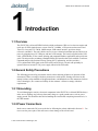
1 Introduction
. . . . . . .
1.1 Overview . . . . . . . . .
1.2 General Safety Precautions . .
1.2.1 Grounding . . . . . .
1.2.2 Power Connections. . .
1.2.3 Environmental Conditions
.
.
.
.
.
.
.
.
.
.
.
.
.
.
.
.
.
.
.
.
.
.
.
.
.
.
.
.
.
.
.
.
.
.
.
.
.
.
.
.
.
.
.
.
.
.
.
.
.
.
.
.
.
.
.
.
.
.
.
.
.
.
.
.
.
.
.
.
.
.
.
.
.
.
.
.
.
.
.
.
.
.
.
.
.
.
.
.
.
.
.
.
.
.
.
.
.
.
.
.
.
.
.
.
.
.
.
.
.
.
.
.
.
.
.
.
.
.
.
.
.
.
.
.
.
.
.
.
.
.
.
.
1
1
1
1
1
2
. .
Powering Up the Unit . . . . . .
2.1.1 USB serial port . . . . . .
2.1.2 Major connections . . . . .
Connecting the GPS Antenna . . .
Remote USB serial control . . . .
2.3.1 “Help” and command overview
2.3.2 Loop parameter adjustment .
Optional Enclosure . . . . . . .
.
.
.
.
.
.
.
.
.
.
.
.
.
.
.
.
.
.
.
.
.
.
.
.
.
.
.
.
.
.
.
.
.
.
.
.
.
.
.
.
.
.
.
.
.
.
.
.
.
.
.
.
.
.
.
.
.
.
.
.
.
.
.
.
.
.
.
.
.
.
.
.
.
.
.
.
.
.
.
.
.
.
.
.
.
.
.
.
.
.
.
.
.
.
.
.
.
.
.
.
.
.
.
.
.
.
.
.
.
.
.
.
.
.
.
.
.
.
.
.
.
.
.
.
.
.
.
.
.
.
.
.
.
.
.
.
.
.
.
.
.
.
.
.
.
.
.
.
.
.
.
.
.
.
.
.
.
.
.
.
.
.
.
.
.
.
.
.
.
.
.
.
.
.
.
.
.
.
.
.
3
3
4
4
5
5
5
6
7
. . .
3.1 Description . . . . . . . . . . . . . . .
3.2 Z38XX Utility . . . . . . . . . . . . . . .
3.2.1 Installation and Set Up . . . . . . . .
3.2.1.1 Parameter Setup . . . . . . .
3.2.1.2 Serial Echo. . . . . . . . . .
3.2.1.3 Windows Compatibility . . . . .
3.2.2 Running the program . . . . . . . . .
3.2.2.1 Zoom and Pan . . . . . . . .
3.2.3 View menu . . . . . . . . . . . . .
3.2.3.1 Satellite Azimuth/Elevation Chart .
3.2.3.2 Satellite C/N level Chart. . . . .
3.2.3.3 Holdover Uncertainty & Sats . . .
3.2.3.4 Time Stability Measures. . . . .
3.3 GPScon Utility . . . . . . . . . . . . . .
3.3.1 Installation and Set Up . . . . . . . .
3.3.1.1 Setting the options . . . . . . .
3.3.1.2 Communication Parameters . . .
3.3.1.3 Auxiliary parameters . . . . . .
3.3.1.4 Other options . . . . . . . . .
3.3.2 Sending manual commands to the receiver
3.3.3 Use of the mouse in graph mode . . . .
3.3.4 Exporting the graphics . . . . . . . .
3.4 Interpreting the Data. . . . . . . . . . . .
3.5 Performance . . . . . . . . . . . . . . .
.
.
.
.
.
.
.
.
.
.
.
.
.
.
.
.
.
.
.
.
.
.
.
.
.
.
.
.
.
.
.
.
.
.
.
.
.
.
.
.
.
.
.
.
.
.
.
.
.
.
.
.
.
.
.
.
.
.
.
.
.
.
.
.
.
.
.
.
.
.
.
.
.
.
.
.
.
.
.
.
.
.
.
.
.
.
.
.
.
.
.
.
.
.
.
.
.
.
.
.
.
.
.
.
.
.
.
.
.
.
.
.
.
.
.
.
.
.
.
.
.
.
.
.
.
.
.
.
.
.
.
.
.
.
.
.
.
.
.
.
.
.
.
.
.
.
.
.
.
.
.
.
.
.
.
.
.
.
.
.
.
.
.
.
.
.
.
.
.
.
.
.
.
.
.
.
.
.
.
.
.
.
.
.
.
.
.
.
.
.
.
.
.
.
.
.
.
.
.
.
.
.
.
.
.
.
.
.
.
.
.
.
.
.
.
.
.
.
.
.
.
.
.
.
.
.
.
.
.
.
.
.
.
.
.
.
.
.
.
.
.
.
.
.
.
.
.
.
.
.
.
.
.
.
.
.
.
.
.
.
.
.
.
.
.
.
.
.
.
.
.
.
.
.
.
.
.
.
.
.
.
.
.
.
.
.
.
.
.
.
.
.
.
.
.
.
.
.
.
.
.
.
.
.
.
.
.
.
.
.
.
.
.
.
.
.
.
.
.
.
.
.
.
.
.
.
.
.
.
.
.
.
.
.
.
.
.
.
.
.
.
.
.
.
.
.
.
.
.
.
. 9
. 9
. 9
. 9
. 10
. 10
. 11
. 12
. 12
. 12
.13
. 13
. 14
. 14
. 16
. 16
. 16
. 16
.17
. 19
. 19
.20
. 22
. 23
. 24
.
.
.
.
.
.
.
.
.
.
.
.
.
.
.
.
.
.
.
.
.
.
.
.
.
.
.
.
.
.
.
.
.
.
.
.
.
.
.
.
.
.
.
.
.
.
.
.
.
.
.
.
.
.
.
.
.
.
.
.
.
.
.
.
.
.
.
.
.
.
.
.
.
.
.
.
.
.
. 27
. 27
. 27
. 27
.27
.28
2 Quick-Start Instructions
2.1
2.2
2.3
2.4
3 Control and Command Utilities
4 SCPI-Control Quick Start Instructions
4.1 Introduction . . . . . .
4.2 General SCPI Commands
4.2.1 *IDN? . . . . . .
4.2.2 HELP?. . . . . .
4.3 GPS Subsystem . . . .
.
.
.
.
.
© 2011 Jackson Labs Technologies, Inc.
.
.
.
.
.
.
.
.
.
.
.
.
.
.
.
.
.
.
.
.
.
.
.
.
.
.
.
.
.
.
.
.
.
.
.
.
.
.
.
.
.
.
.
.
.
i
GPSTCXO Eval Board User Manual
4.4
4.5
4.6
4.7
4.8
4.9
ii
4.3.1 GPS:SATellite . . . . . . . . . . . . . . . . .
4.3.2 GPS:SATellite:TRAcking:COUNt? . . . . . . . . .
4.3.3 GPS:SATellite:VISible:COUNt? . . . . . . . . . .
4.3.4 NMEA Support . . . . . . . . . . . . . . . . .
4.3.5 GPS:GPGGA. . . . . . . . . . . . . . . . . .
4.3.6 GPS:GGASTat . . . . . . . . . . . . . . . . .
4.3.7 GPS:GPRMC . . . . . . . . . . . . . . . . .
4.3.8 GPS:XYZSPeed . . . . . . . . . . . . . . . .
4.3.9 GPS:POSition? . . . . . . . . . . . . . . . . .
4.3.10GPS:RESET ONCE . . . . . . . . . . . . . . .
4.3.11GPS?. . . . . . . . . . . . . . . . . . . . .
PTIME Subsystem . . . . . . . . . . . . . . . . . .
4.4.1 PTIMe:TZONe? . . . . . . . . . . . . . . . . .
4.4.2 PTIMe:DATE? . . . . . . . . . . . . . . . . .
4.4.3 PTIMe:TIME? . . . . . . . . . . . . . . . . .
4.4.4 PTIMe:TIME:STRing? . . . . . . . . . . . . . .
4.4.5 PTIMe:TINTerval? . . . . . . . . . . . . . . . .
4.4.6 PTIME? . . . . . . . . . . . . . . . . . . . .
SYNChronization Subsystem . . . . . . . . . . . . . .
4.5.1 SYNChronization:SOURce:MODE [GPS|EXTernal|AUTO]
4.5.2 SYNChronization:HOLDover:DURation? . . . . . . .
4.5.3 SYNChronization:HOLDover:INITiate . . . . . . . .
4.5.4 SYNChronization:HOLDover:RECovery:INITiate . . . .
4.5.5 SYNChronization:TINTerval? . . . . . . . . . . .
4.5.6 SYNChronization:IMMEdiate. . . . . . . . . . . .
4.5.7 SYNChronization:FEEstimate? . . . . . . . . . . .
4.5.8 SYNChronization:LOCKed? . . . . . . . . . . . .
4.5.9 SYNChronization:health? . . . . . . . . . . . . .
4.5.10SYNChronization?. . . . . . . . . . . . . . . .
DIAGnostic Subsystem . . . . . . . . . . . . . . . .
4.6.1 DIAGnostic:ROSCillator:EFControl:RELative? . . . . .
4.6.2 DIAGnostic:ROSCillator:EFControl:ABSolute? . . . . .
MEASURE Subsystem . . . . . . . . . . . . . . . .
4.7.1 MEASure:VOLTage?. . . . . . . . . . . . . . .
4.7.2 MEASure:CURRent?. . . . . . . . . . . . . . .
4.7.3 MEASure? . . . . . . . . . . . . . . . . . . .
SYSTEM Subsystem . . . . . . . . . . . . . . . . .
4.8.1 SYSTem:COMMunicate . . . . . . . . . . . . .
4.8.1.1 SYSTem:COMMunicate:SERial:ECHO . . . .
4.8.1.2 SYSTem:COMMunicate:SERial:PROmpt . . .
4.8.1.3 SYSTem:COMMunicate:SERial:BAUD . . . .
4.8.2 SYSTem:STATus? . . . . . . . . . . . . . . .
4.8.3 SYSTem:FACToryReset ONCE . . . . . . . . . .
SERVO Subsystem. . . . . . . . . . . . . . . . . .
4.9.1 SERVo:COARSeDac . . . . . . . . . . . . . .
4.9.2 SERVo:DACGain . . . . . . . . . . . . . . . .
4.9.3 SERVo: EFCScale . . . . . . . . . . . . . . .
4.9.4 SERVo:EFCDamping . . . . . . . . . . . . . .
4.9.5 SERVo:SLOPe . . . . . . . . . . . . . . . . .
4.9.6 SERVo:TEMPCOmpensation . . . . . . . . . . .
4.9.7 SERVo:AGINGcompensation . . . . . . . . . . .
4.9.8 SERVo:PHASECOrrection . . . . . . . . . . . .
.
.
.
.
.
.
.
.
.
.
.
.
.
.
.
.
.
.
.
.
.
.
.
.
.
.
.
.
.
.
.
.
.
.
.
.
.
.
.
.
.
.
.
.
.
.
.
.
.
.
.
.
.
.
.
.
.
.
.
.
.
.
.
.
.
.
.
.
.
.
.
.
.
.
.
.
.
.
.
.
.
.
.
.
.
.
.
.
.
.
.
.
.
.
.
.
.
.
.
.
.
.
.
.
.
.
.
.
.
.
.
.
.
.
.
.
.
.
.
.
.
.
.
.
.
.
.
.
.
.
.
.
.
.
.
.
.
.
.
.
.
.
.
.
.
.
.
.
.
.
.
.
.
.
.
.
.
.
.
.
.
.
.
.
.
.
.
.
.
.
.
.
.
.
.
.
.
.
.
.
.
.
.
.
.
.
.
.
.
.
.
.
.
.
.
.
.
.
.
.
.
.
.
.
.
.
.
.
.
.
.
.
.
.
.
.
.
.
.
.
.
.
.
.
.
.
.
.
.
.
.
.
.
.
.
.
.
.
.
.
.
.
.
.
.
.
.
.
.
.
.
.
.
.
.
.
.
.
.
.
.
.
.
.
.
.
.
.
.
.
.
.
.
.
.
.
.
.
.
.
.
.
.
.
.
.
.
.
.
.
.
.
.
.
.
.
.
.
.
.
.
.
.
.
.
.
.
.
.
.
.
.
.
.
.
.
.
.
.
.
.
.
.
.
.
.
.
.
.
.
.
.
.
.
.
.
.
.
.
.
.
.
.
.
.
.
.
.
.
.
.
.
.
.
.
.
.
.
.
.
.
.
.
.
.
.
.
.
.
.
.
.
.
.
.
.
.
.
.
.
.
.
.
.
.
.
.
.
.
.
.
.
.
.
.
.
.
.
.
.
.
.
.
.
.
.
.
.
.
.
.
.
.
.
.
.
.
.
.
.
.
.
.
.
.
.
.
.
.
.
.
.
.
.
.
.
.
.
.
.
.
.
.
.
.
.
.
.
.
.
.
.
.
.
.
.
.
.
.
.
.
.
.
.
.
.
.
.
28
28
28
28
29
29
29
30
30
30
30
30
30
31
31
31
31
31
31
32
32
32
32
32
32
33
33
33
34
34
34
34
34
35
35
35
35
35
35
35
35
36
36
36
36
36
36
37
37
37
37
37
© 2011 Jackson Labs Technologies, Inc.
GPSTCXO Eval Board User Manual
4.9.9 SERVo:1PPSoffset . . . . . . . . . . . . . . . . . . . . . . . . . 37
4.9.10SERVo:TRACe . . . . . . . . . . . . . . . . . . . . . . . . . . 38
4.9.11SERVo? . . . . . . . . . . . . . . . . . . . . . . . . . . . . . 38
5 Certification and Warranty .
.
5.0.1 Warranty . . . . . . . . . .
5.0.2 Limitation of Warranty . . . . .
5.0.3 Exclusive Remedies . . . . .
© 2011 Jackson Labs Technologies, Inc.
.
.
.
.
.
.
.
.
.
.
.
.
.
.
.
.
.
.
.
.
.
.
.
.
.
.
.
.
.
.
.
.
.
.
.
.
.
.
.
.
.
.
.
.
.
.
.
.
.
.
.
.
.
.
.
.
.
.
.
.
.
.
.
.
.
.
.
.
.
.
.
.
. 41
. 41
. 41
. 41
iii
GPSTCXO Eval Board User Manual
iv
© 2011 Jackson Labs Technologies, Inc.
GPSTCXO Eval Board User Manual
1
Introduction
1.1 Overview
The GPSTCXO eval board GPSDO includes a high-performance GPS receiver that can acquire and
track up to 50 GPS signals down to a state of the art –160dBm, a 32bit processor that runs a Real
Time OS, a low-noise 5V CMOS 10MHz output, USB control interface, precision voltage
references, and DACs. The unit is built as an easy-to-use evaluation board that operates and receives
power by plugging into a PC USB port, and into a GPS antenna. The board is supplied with a USB
cable, a GPS antenna, Z38xx control, plotting, and command Windows application, and a quick-start
guide. The unit provides an industry-standard NMEA GPS interface that can be enabled via software
command and provides Position/Velocity/Timing (PVT) information, and also provides a
UTC-synchronized 1PPS signal on the USB serial port DCD# pin. The unit can optionally be
operated from an external 5V DC power supply instead of the USB cable.
1.2 General Safety Precautions
The following general safety precautions must be observed during all phases of operation of this
instrument. Failure to comply with these precautions or with specific warnings elsewhere in this
manual violates safety standards of design manufacture, and intended use of the instrument. Jackson
Labs Technologies, Inc. assumes no liability for the customer’s failure to comply with these
requirements.
1.2.1 Grounding
To avoid damaging the sensitive electronic components in the GPSTCXO eval board GSPDO always
make sure to discharge any built-up electrostatic charge to a good ground source, such as power
supply ground. This should be done before handling the circuit board or anything connected to it, i.e.
the GPS antenna.
1.2.2 Power Connections
Make sure to connect the DC power to the device following the polarity indicated in Section 2.1 . Do
not reverse the power pins as this will cause serious damage to the circuit board.
© 2011 Jackson Labs Technologies, Inc.
1
GPSTCXO Eval Board User Manual
1.2.3 Environmental Conditions
This instrument is intended for indoor use. It is designed to operate at a maximum relative
non-condensing humidity of 95% and at altitudes of up to 4000 meters. Refer to the specifications
tables for the ac mains voltage requirements and ambient operating temperature range.
2
© 2011 Jackson Labs Technologies, Inc.
GPSTCXO Eval Board User Manual
2
Quick-Start
Instructions
2.1 Powering Up the Unit
The unit is powered directly from the USB cable, OR from a 5V DC source on connector JP2. Do not
connect both the USB cable and the external 5V DC source at the same time, this will lead to possible
damage to the PC or the 5V DC power supply. The current is typically less than 0.15A at 5V. Connect
a clean +5V power supply to JP2 if the USB cable is not going to be used. See Figure 2.1 for the
proper polarity of the optional external 5V DC power connection.
Warning: Do not reverse the polarity on the power connector, this will damage the unit.
When using the unit through the USB cable, Windows Vista, Windows-7 and Linux will
auto-recognize the unit as a USB serial COM adaptor, and automatically assign a serial port to the
unit. Windows will automatically load the USB COM driver for the board. The user can verify the
COM port that windows assigned to the unit under the Computer Management window (right click
on computer and press the “MANAGE” button under Windows-7, or go to Control Panel/Computer
Management). The unit should show up as a standard serial port adaptor under the “Ports (COM&
LPT) Icon. Please note down this port number, as it is required for the initialization of application
software.
The unit will start to search for Satellites as soon as power is applied, and will start to lock the
internal TCXO to UTC as soon as the Red LED starts blinking with the GPS antenna attached. After
1 hour or less, the unit should stabilize the frequency, and all event indicators should be off resulting
in the Green LED to be lit up. At this time the Green LED will indicate the unit is fully synchronized
to UTC, and generating a stable and accurate 10MHz output signal. The Green LED may go off
momentarily as airflow touches the unit or Sats come in and out of view, this is normal behavior.
You may place the GPS antenna in a window, but it is recommended to place the GPS antenna with a
full view of the sky for best performance. The antenna cable can be extended to 10m or more with
high quality antenna cable (use quad shielded RG-6 75 Ohms cable, or high-quality 50 Ohms coax
cable) without significant loss of signal quality.
© 2011 Jackson Labs Technologies, Inc.
3
GPSTCXO Eval Board User Manual
2.1.1 USB serial port
The GPSTCXO eval board has an internal RS-232 to USB serial port adaptor. This allows the unit to
be directly connected to a PC’s USB port, from which it will receive power and serial control, and no
external RS-232 to USB adaptor is required. The term “RS-232” and USB serial port are used
interchangeably, as the RS-232 port is implemented and connected via the USB serial connection.
Windows and Linux has built-in support for this serial port functionality.
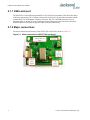
2.1.2 Major connections
The major connections and features of the GPSTCXO eval PCB are shown in :Figure 2.1.
Figure 2.1
4
Major connections to GPSTCXO eval board
© 2011 Jackson Labs Technologies, Inc.
GPSTCXO Eval Board User Manual
Table 2.1 shows the GPSTCXO eval board revision 2.0 hardware connectors
Table 2.1 GPSTCXO eval board hardware connectors
Ref
Name
Function
Specification
Pinning
JP2
+5V
Clean +5V Supply
5V DC +/-10%, <0.15A, <10mVac
1 +5V, 2-GND
J1
10MHz CMOS
Out
10MHz Output
+5V CMOS 10MHz Output
Center-10MHz Output, Shield-GND
U3
USB Port
Supplies Power and
control
Standard USB 2.0 Full Speed
Mini USB
2.2 Connecting the GPS Antenna
Connect the GPS antenna to the MMCX connector shown in Figure 2.1. Please make sure to connect
the GPS antenna prior to connecting the USB or power cable to the unit.
Caution: use a Lightning Arrestor on your Antenna setup.
The GPSTCXO eval board GPS receiver includes a 50 channel high-sensitivity GPS receiver with
very fast lock time. It does not require any self-survey or position-hold mode (auto survey), and thus
can be used in mobile platforms.
The GPSTCXO eval board is capable of generating standard navigation messages (see GPS:GPGGA
and GPS:GPRMC RS-232 commands) that are compatible with most GPS based navigation
software. Please note that GPSTCXO eval board indicates MSL height (rather than GPS height) in its
GPGGA, GPS? and syst:stat? output strings.
The GPS receiver generates a 1PPS time signal that is phase synchronized to UTC. This 1PPS signal
is used to frequency-lock the 10MHz Sine-Wave output of the GPSTCXO eval board GPSDO to
UTC, thus disciplining the unit’s 10MHz frequency output to the US Naval master clock for very
high frequency accuracy (typically better than 2ppb of frequency accuracy when locked to GPS).
Over the long term, the GPSTCXO eval board will out-perform free-running Cesium Atomic
Frequency Standards.
2.3 Remote USB serial control
• The unit is controlled via the USB Serial port at 115200 baud, 8N1. Other Baud Rates can be set
via SCPI commands over the serial port.
• Connect the PC via the USB cable and connector, attaching the GPSTCXO eval board unit to your
PC’s Hyperterminal, or the Z38xx software available on the included CD ROM, or the optional
GPSCon software package. Please initialize your PC application software to the proper COM port
(automatically assigned by Windows) and configure the application software for 115200 Baud, 8
bits, no parity, 1 stop bit, and no flow control where applicable.
2.3.1 “Help” and command overview
• A listing of the available USB/RS-232 commands can be shown by typing "help?" when using
TeraTerm (recommended) or Hyperterm.
© 2011 Jackson Labs Technologies, Inc.
5
GPSTCXO Eval Board User Manual
• "*IDN?" can be used to see if the connection works. Both commands need to be followed by
pressing “Enter”.
2.3.2 Loop parameter adjustment
• All loop parameters can be controlled via the RS-232 serial port.
• Loop parameters are optimized for the OCXO on the board, and changing the factory settings may
result in the unit’s performance to deteriorate.
The commands to control the loop parameters are part of the servo? command. See also the SERVO
Subsystem section in Chapter 3 (Section 4.9 ).
The individual commands are:
EFC Scale: this is the proportional gain of the PID loop. Higher values will give quicker
convergence, and faster locking of the GPS time (lower loop time constant), lower values give less
noise. Values between 0.7 and 6.0 are typical.
EFC Damping: overall IIR filter time constant. Higher values increase loop time constant. Jackson
Labs Technologies, Inc. typically uses values between 10 to 50. Setting this value too high may cause
loop instability.
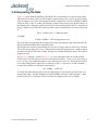
Phase compensation: this is the Integral part of the PID loop. This corrects phase offsets between the
GPSTCXO eval board 1PPS signal and the UTC 1PPS signal as generated by the GPS receiver. Set
higher values for tighter phase-following at the expense of frequency stability. Typical values range
from 4 - 30, 25 being the default. Setting this value too high may cause loop instability.
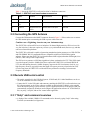
A well-compensated unit will show performance similar to the plot in Figure 2.2 when experiencing
small perturbations
6
© 2011 Jackson Labs Technologies, Inc.
GPSTCXO Eval Board User Manual
Figure 2.2
GPSTCXO eval board phase compensation plot
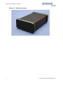
2.4 Optional Enclosure
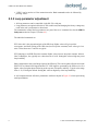
The GPSTCXO eval board may be inserted into a Hammond enclosure (pictured in Figure 2.3) to
shield it from airflow and temperature changes. Frequency stability will improve significantly when
the unit is operated inside an enclosure. The enclosure sides will have to be drilled or stamped by the
user to provide clearance for the GPSTCXO eval board.
The Hammond enclosure into which the GPSTCXO eval board fits has the part number:
Hammond, PN: 1455C801BK
It is available at www.mouser.com
© 2011 Jackson Labs Technologies, Inc.
7
GPSTCXO Eval Board User Manual
Figure 2.3
8
Hammond enclosure
© 2011 Jackson Labs Technologies, Inc.
GPSTCXO Eval Board User Manual
3
Control and Command
Utilities
3.1 Description
The GPSTCXO eval board comes with a CD including a freeware program to control and monitor
the unit called Z38xx. This program runs under Windows, and the latest version is also available on
the Jackson Labs Technologies, Inc. website (www.jackson-labs.com) under the Support tab.
Z38xx can be used to monitor and graphically plot the frequency and phase stability of the unit, the
number of Satellites being tracked, and various other GPS and TCXO performance parameters.
Z38xx needs to be properly configured under the “PARAMETERS” tab prior to operation by setting
up the correct serial parameters (115.2KBaud, 8N1).
Please consult the Z38xx user manual included in the CD ROM for further details.
Alternatively to the Z38xx application, GPSCon is a third-party program for the monitoring and
control of a variety of GPS time and frequency standard receivers. It communicates with the receiver
using the SCPI command set via the USB port. This utility can be obtained directly from Real Ham
Radio.com at the following URL:
http://www.realhamradio.com/gpscon-buy-now.htm
Important note: On newer, faster computers running Windows 7, GPSCon may not acquire data
correctly. If you encounter this problem, it is recommended that you install GPSCon on a slower
computer using Windows XP, or try running GPSCon in Windows XP compatibility mode.
3.2 Z38XX Utility
3.2.1 Installation and Set Up
The Z38XX manual has instructions on how to install and set up the software. All the information
needed to run the program is available in the included user manual. Only some details of setup and
use will be provided here for convenient reference.
© 2011 Jackson Labs Technologies, Inc.
9
GPSTCXO Eval Board User Manual
3.2.1.1 Parameter Setup
Before communication with Z38XX can take place, the communications parameters must be set. To
do so, click on the Parameters tab. The parameter window will appear as shown in Figure 3.1.
Figure 3.1
Z38XX parameter window
Set the communications parameters as follows:
•
•
•
•
•
Comm port: Windows will assign a comm port. Enter that number in the Com box.
Baudrate: 115,200
Data bits: 8 bits
Stop bits: 1
Parity: none
3.2.1.2 Serial Echo
For serial communication with Z38XX to work correctly, Serial Echo must be turned off (see the
explanation in the Z38XX manual). To turn off serial echo, click on the Manual Command Entry tab.
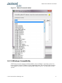
The drop-down menu shown in Figure 3.2 will appear. Scroll all the way down and click on
SYST:COMM:SER:ECHO OFF. Wait until the yellow indicator is lit and then press “Send”. This
will send a command to the GPSTCXO and turn off serial echo.
Note: If you want to run GSPcon utility subsequently, be sure and turn back on Serial
Echo as that program requires it. To do so, click on the Manual Command Entry tab
and scroll down to the menu item SYST:COMM:SER:ECHO ON. Wait until the yellow
indicator is lit and then press ”Send”.
10
© 2011 Jackson Labs Technologies, Inc.
GPSTCXO Eval Board User Manual
Figure 3.2
Manual Command window
3.2.1.3 Windows Compatibility
Z38XX may not operate properly under the Windows Vista or Windows 7 operating systems. It is
best to start these versions of Windows in XP Compatibility Mode. This will ensure proper operation
of the program. Of course, you can try running under Windows Vista or 7 as it does work on some
systems.
© 2011 Jackson Labs Technologies, Inc.
11
GPSTCXO Eval Board User Manual
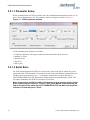
3.2.2 Running the program
When Z38XX starts up, the main window appears, as shown in Figure 3.3. The window can be
moved or resized as desired. It is necessary to wait about 20 seconds after starting the program for the
software to establish communications with the GPSTCXO.
The main graph shows the EFC (Electronic Frequency Control) digital control value (scale on the
right) in red, and the GPSR 1pps TI (compared with the mean GPS derived 1pps) in blue (scale on the
left). The graph is auto-scaling on both parameters.
3.2.2.1 Zoom and Pan
In the main graph window, you can zoom in to get more detail. To do so, position the cursor at the
bottom or top of the screen next to the beginning of the area you wish to zoom in on. Using the left
mouse button, drag the cursor up and to the right (or down and to the left) to the end of the desired
zoom area. When you release the mouse button, the display will zoom in on the desired area. To
unzoom, drag the cursor in the opposite direction, from the bottom right up and left (or from the top
down and left). The display will return to the full graph again.
To pan within the graph display, use the right mouse button to drag the graph around the window.
Figure 3.3
Z38XX main window
3.2.3 View menu
The View menu allows you to view different aspects of the GPSTCXO performance such as:
•
•
•
•
•
•
12
Satellite Azimuth/Elevation Chart
Satellite C/N level Chart
Time Stability measures
Clock Display
EFC Statistics
Receiver Status
© 2011 Jackson Labs Technologies, Inc.
GPSTCXO Eval Board User Manual
• Status Log
• Error Log
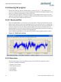
3.2.3.1 Satellite Azimuth/Elevation Chart
From the drop-down View menu select Satellite Azimuth/Elevation Chart. You will see a polar graph
like the one shown in Figure 3.4. It may take a few hours for the graph to display all the satellites
within your antenna’s view. The chart changes over time as the satellites move in and out of view.
Figure 3.4
Satellite Azimuth/Elevation chart
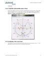
3.2.3.2 Satellite C/N level Chart
Select Satellite C/N level Chart from the View menu and observe the chart shown in Figure 3.5. This
graph show the Carrier to Noise ratio of each satellite being tracked.
© 2011 Jackson Labs Technologies, Inc.
13
GPSTCXO Eval Board User Manual
Figure 3.5
Satellite C/N/chart
3.2.3.3 Holdover Uncertainty & Sats
These parameters are not supported by the GPSTCXO.
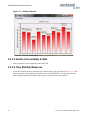
3.2.3.4 Time Stability Measures
Select Time Stability Measures from the View menu to bring up the chart shown in Figure 3.6. This
chart is primarily used to display the Allan Deviation for the GPSTCXO. To learn more about the
different display parameters for this window, please consult the Z8XX User Manual.
14
© 2011 Jackson Labs Technologies, Inc.
GPSTCXO Eval Board User Manual
Figure 3.6
Time Stability measures window
© 2011 Jackson Labs Technologies, Inc.
15
GPSTCXO Eval Board User Manual
3.3 GPScon Utility
3.3.1 Installation and Set Up
Follow the directions that come with GPSCon for installing the utility on your computer. The
GPSCon utility has a help file that should be consulted in order to get the full functionality of this
utility. Only a few of the features and commands are mentioned in this chapter for convenience.
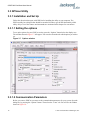
3.3.1.1 Setting the options
To set up the options for your GPSCon session, press the “Options” button below the display area.
The window shown in Figure 3.7 will appear. You can select from the tabs which options you wish to
set.
Figure 3.7
Options window
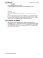
3.3.1.2 Communication Parameters
Before you can use GPSCon you must set the communication parameters for your system. Open the
dialog box by pressing the “Options” button. Then select the “Coms” tab. You will see the window
shown in Figure 3.8.
16
© 2011 Jackson Labs Technologies, Inc.
GPSTCXO Eval Board User Manual
Set the communications parameters as follows:
•
•
•
•
•
•
Comm port: Windows will assign a comm port. Enter that number in the Com box.
Baudrate: 115,200
Data bits: 8 bits
Stop bits: 1
Parity: none
Flow Control: “None”
Once you have configured the communication parameters, press the “OK” button to close the
window.
For proper communication between the GPSTXCO and GPScon, SYST:COMM:SER:ECHO must
be set to ON. Although this is the factory default, it could have been set to OFF for use with the
Z38XX utility. To set it to ON, open the manual command dialog box (see Section 3.3.2 ). Manually
enter the command SYST:COMM:SER:ECHO ON and press the Send button.
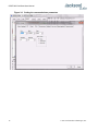
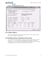
3.3.1.3 Auxiliary parameters
After pressing the “Options” button, you can select “Auxiliary” and set other options or
measurements. See Figure 3.9 for an example of an auxiliary measurement. You will notice that the
“Aux 1 request string” has been set to meas:current?<CD> and the “Log Aux1” box is checked.
In the area below labeled “Traces to be visible on the graph”, the box “Aux 1” is checked and the
label “OCXO curr” has been added.
© 2011 Jackson Labs Technologies, Inc.
17
GPSTCXO Eval Board User Manual
Figure 3.8
18
Setting the communications parameters
© 2011 Jackson Labs Technologies, Inc.
GPSTCXO Eval Board User Manual
Figure 3.9
Auxiliary Parameters window
3.3.1.4 Other options
The other tabs in the options window can be selected and you can set whatever options you need,
such as paths for logging or exporting graphics.
3.3.2 Sending manual commands to the receiver
You can send SCPI commands manually by using the drop-down box under the display window as
shown in Figure 3.10. Care must be taken when sending these commands so be sure that the
command that you select is supported by the GPSTCXO eval board GPSDO. Once you’ve selected
the command, you can press “Send” to send it to the GPSTCXO eval board.
© 2011 Jackson Labs Technologies, Inc.
19
GPSTCXO Eval Board User Manual
Figure 3.10 Sending manual commands
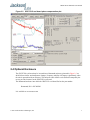
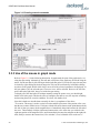
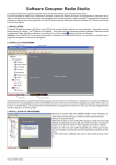
3.3.3 Use of the mouse in graph mode
Refer to Figure 3.11 for the following description. In graph mode the span of the graph may be set
using the span setting. Alternatively, the start and or stop time of the graph may be locked using the
mouse. Set the start time by left clicking on the desired start point. If you wish, the stop time may also
be locked by right clicking the desired stop point. This can all be unlocked by left double-clicking
anywhere on the graph. Double-click always causes all of the selected span data to be displayed. At
the next update cycle, the selected span, if not set to zero, will be enforced. However, the left click,
and if chosen the right click, always overrides the span setting.
To display all of the data in the file without manually setting the span to zero, you should right
double-click in the graph. This has the effect of setting the start time to zero, the stop time to infinity,
and asserting the mouse override condition. To release, left double-click.
Since this is harder to describe than to actually do, here is a paraphrase of the above:
"To zoom in: The mouse is used to set the left extent and the right extent of the portion of the curve
that the user wants to fill the screen. Click once with the left mouse button on the point that marks the
left side of what you want to be the magnified curve. Immediately that point becomes the left end of
the curve. Then similarly click the right mouse button on the curve at the time you wish to be the
right most portion of the magnified curve and it immediately becomes the end point on the right side.
And, finally to return to the zoomed out ("fit to window") view, left double-click on the curve."
20
© 2011 Jackson Labs Technologies, Inc.
GPSTCXO Eval Board User Manual
Remember, in order to see all the data in the log file, you must either set the span control to zero, or
right double-click in the graph.
When you have locked the start and stop time using the mouse, you can scroll left or right through the
data without changing the span. To scroll to a later time, use Shift + Left click. To scroll to an earlier
time, use Shift + Right click. Double left click to release everything.
The time span indication at the lower right of the graph will turn red to signify that mouse override is
in effect.
Figure 3.11 Graph display
© 2011 Jackson Labs Technologies, Inc.
21
GPSTCXO Eval Board User Manual
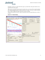
Figure 3.12 Expanded Graph Display
3.3.4 Exporting the graphics
The settings which control the mode of the Export function are contained in the Options dialog.
Export allows you to create an image file of either the graph or the satellite map. You select which
you want using the radio buttons. If you select 'Graph', you have the option to export only that which
is currently visible, or to export the graph which is a plot of the entire logfile contents. Use the
checkbox "All" to make this choice.
You may nominate a size in X and Y. The file format may be .BMP, .JPG, .GIF, or .PNG. Your settings
will be stored and will be the default next time you open this dialog.
If you choose to export the graph, you might want to override the TI max setting in force on the
screen display. You may do this by entering a non-zero value into the 'Override TI' control. A value
of zero causes the export to take the same setting if any as the screen display.
The export may be done automatically on a timed basis. Simply enter a non-zero value in seconds to
choose an export time interval. To manually export in accordance with the settings, press the 'Export'
button.
22
© 2011 Jackson Labs Technologies, Inc.
GPSTCXO Eval Board User Manual
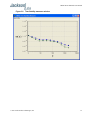
3.4 Interpreting the Data
Figure 3.11 shows the data acquired by the GPSTCXO eval board unit over a period of more than
200 hours The red trace is EFC (crystal frequency control voltage). The crystal is aging (becoming
faster in frequency over time). This requires the control voltage to be lowered to maintain 10.0MHz
exactly. A drift of ~2mV is visible over 200 hours. On the left side of the screen the EFC range over
this 200 hour plot is displayed vertically as 0.00193V. This means the drift of the EFC voltage due to
aging is ~88mV per year. The EFC sensitivity of the crystal is about 8Hz per volt, so the crystal ages
at:
8Hz/V * 0.088V/Year = 0.704Hz/Year drift.
At 10MHz:
0.704Hz / 10MHz = 7.04E-08 aging rate per year.
This is the same as 0.2ppb drift due to aging per day.This crystal aging is fully compensated by the
firmware with and without GPS reception of course.
The OCXO heater current is shown in turqoise. We can see it ranges from 0.135607A to 0.178146A.
The OCXO current jumps lower every 24 hours because the unit is sitting next to a window, and the
sun shines onto the OCXO in the evenings, heating it up, and thus making the unit use lower power
during that event.
In Figure 3.12, which is a zoom of Figure 3.11, we can see the phase offset error of the internal
OCXO to the UTC GPS reference. We can see the maximum drift is -77ns to +93ns. The average is
(TI av=-0.03ns). The standard deviation over the 200 hour plot is sd=11ns. This means the average
error of the 10MHz phase of this unit over 200 hours is only +/-11ns rms. Or, in other words the
average jitter (wander) over 200 hours of operation is:
11ns / 200Hrs = 1.528E-014
or in other words the unit performs as well as a high quality Cesium Atomic reference clock over
long periods of time. The unit disciplines its internal 10MHz reference to within less than +/-80ns
peak to peak of UTC at all times, which is less than one complete clock cycle at 10MHz.
© 2011 Jackson Labs Technologies, Inc.
23
GPSTCXO Eval Board User Manual
3.5 Performance
Some typical performance parameters for the GPSTCXO Eval board are shown in the following
figures.
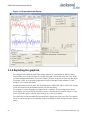
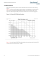
Figure 3.13 shows the typical Allan Deviation performance of the GPSTCXO eval board after one
week of burn-in, locked to GPS and shielded from airflow. Corrections from the GPS receiver
improve the short term phase stability of the TCXO oscillator above 50-second averaging times.
Figure 3.13 Typical GPSTCXO Allan Deviation
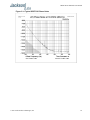
Figure 3.14 is a plot of typical GPSTCXO eval board phase noise performance while locked to GPS.
The noise floor can be seen to be below -155dBc.
24
© 2011 Jackson Labs Technologies, Inc.
GPSTCXO Eval Board User Manual
Figure 3.14 Typical GPSTCXO Phase Noise
© 2011 Jackson Labs Technologies, Inc.
25
GPSTCXO Eval Board User Manual
26
© 2011 Jackson Labs Technologies, Inc.
GPSTCXO Eval Board User Manual
4
SCPI-Control Quick
Start Instructions
4.1 Introduction
The SCPI (Standard Commands for Programmable Instrumentation) subsystem is accessed via the
USB RS-232 interface and a terminal program. By default the terminal settings are 115200, 8N1. Use
terminal programs such as TeraTerm (recommended) or Hyperterm, or use the command and control
window functions of Z38xx or GPSCon application programs to send commands to the GPSTCXO
eval board.
There are a number of commands that can be used as listed below. Most of these are identical or
similar to Symmetricom 58503A commands.To get a listing of the available commands, send the
HELP? query. This will return a list of all the available commands for the GPSTCXO eval board
GPSDO.
Additional information regarding the SCPI protocol syntax can be found on the following web site:
http://www.scpiconsortium.org
Please refer to the document SCPI-99.pdf for details regarding individual SCPI command
definitions. A basic familiarity with the SCPI protocol is recommended when reading this chapter.
4.2 General SCPI Commands
4.2.1 *IDN?
This query outputs an identifying string. The response will show the following information:
<company name>, <model number>, <serial number>, <firmware revision>
4.2.2 HELP?
This query returns a list of the commands available for the GPSTCXO GPSDO.
© 2011 Jackson Labs Technologies, Inc.
27
GPSTCXO Eval Board User Manual
4.3 GPS Subsystem
Note: Please note that GPSTCXO eval board displays antenna height in MSL Meters rather than in
GPS Meters on all commands that return antenna height [the legacy Fury GPSDO uses GPS height].
The GPS subsystem regroups all the commands related to the control and status of the GPS receiver.
The list of the commands supported is the following :
GPS:SATellite:TRAcking:COUNt?
GPS:SATellite:VISible:COUNt?
GPS:GPGGA <int> [0,255]
GPS:GGASTat <int> [0,255]
GPS:GPRMC <int> [0,255]
GPS:XYZSPeed <int> [0,255]
GPS:POSition?
GPS:RESET ONCE
GPS
4.3.1 GPS:SATellite
This group of commands describe the satellite constellation.
4.3.2 GPS:SATellite:TRAcking:COUNt?
This query returns the number of satellites being tracked.
4.3.3 GPS:SATellite:VISible:COUNt?
This query returns the number of satellites (PRN) that the almanac predicts should be visible, given
date, time, and position.
4.3.4 NMEA Support
The following two commands allow the GPSTCXO eval board GPSDO to be used as an industry
standard navigation GPS receiver. The GPGGA and GPRMC NMEA commands comprise all
necessary information about the antenna position, height, velocity, direction, satellite info, fix info,
time, date and other information that can be used by standard navigation applications via the
GPSTCXO eval board RS-232 interface.
Once enabled, GPSTCXO eval board will send out information on the RS-232 transmit pin
automatically every N seconds. All incoming RS-232 commands are still recognized by GPSTCXO
eval board since the RS-232 interface transmit and receive lines are completely independent of one
another.
28
© 2011 Jackson Labs Technologies, Inc.
GPSTCXO Eval Board User Manual
Please note that the position, direction, and speed data is delayed by one second from when the GPS
receiver internally reported these to the GPSTCXO eval board Microprocessor, so the position is
valid for the 1PPS pulse previous to the last 1PPS pulse at the time the data is sent (one second
delay). The time and date are properly output with correct UTC synchronization to the 1PPS pulse
immediately prior to the data being sent.
Once set, the following two commands will be stored in NV memory, and generate output
information even after power to the unit has been cycled.
4.3.5 GPS:GPGGA
This command instructs the GPSTCXO eval board to send the NMEA standard string $GPGGA
every N seconds, with N in the interval [0,255]. The command is disabled during the initial 4 minute
OCXO warmup phase.
This command has the following format:
GPS:GPGGA <int> [0,255]
GPGGA shows height in MSL Meters, this is different from traditional GPS receivers that display
height in GPS Meters. The difference between MSL and GPS height can be significant, 35m or more
are common.
4.3.6 GPS:GGASTat
This command instructs the GPSTCXO eval board to send a modified version of the NMEA standard
string $GPGGA every N seconds, with N in the interval [0,255]. The command is disabled during the
initial 7 minute OCXO warmup phase.
This command has the following format:
GPS:GGASTat <int> [0,255]
This command replaces the regular NMEA GGA validity flag with a decimal number indicating the
lock-state of the unit. Please see section SERVo:TRACe for a detailed description of the lock state
variable. The command allows capture of the position and other information available in the GGA
command, as well as tracking the lock state and health of the unit’s OCXO performance.
GGASTat shows height in MSL Meters, this is different from traditional GPS receivers that display
height in GPS Meters. The difference between MSL and GPS height can be significant, 35m or more
are common.
4.3.7 GPS:GPRMC
This command instructs the GPSTCXO eval board to send the NMEA standard string $GPRMC
every N seconds, with N in the interval [0,255]. The command is disabled during the initial 4 minute
OCXO warmup phase.
This command has the following format:
GPS:GPRMC <int> [0,255]
© 2011 Jackson Labs Technologies, Inc.
29
GPSTCXO Eval Board User Manual
4.3.8 GPS:XYZSPeed
Firmware version 0.909 and later add a 3D velocity vector output command. Enabling this command
will output a 3 dimensional velocity vector indicating the unit’s speed in centimeters per second as
well as the Time Of Week in milliseconds.
X, Y, and Z speed are individually given, and are independent of each other. An accuracy estimate in
centimeters per second is also given. The velocity data is time-stamped using the time-of-week with
a resolution of milliseconds. Use the following format to generate the velocity vector every N
seconds, with N in the interval [0,255]:
GPS:XYZSPeed <int> [0,255]
4.3.9 GPS:POSition?
This command will return the position and height of the GPS antenna, including velocity and track
over ground.
4.3.10 GPS:RESET ONCE
This command will re-initialize the GPS receiver.
4.3.11 GPS?
This query displays the configuration, position, speed, height and other relevant data of the GPS
receiver in one convenient location.
4.4 PTIME Subsystem
The PTIME subsystem regroups all the commands related to the management of the time.The list of
the commands supported is the following :
PTIMe:TZONe?
PTIMe:DATE?
PTIMe:TIME?
PTIMe:TIME:STRing?
PTIMe:TINTerval?
PTIME?
4.4.1 PTIMe:TZONe?
Returns the local time zone offset.
30
© 2011 Jackson Labs Technologies, Inc.
GPSTCXO Eval Board User Manual
4.4.2 PTIMe:DATE?
This query returns the current calendar date. The local calendar date is referenced to UTC time. The
year, month, and day are returned.
4.4.3 PTIMe:TIME?
This query returns the current 24-hour time. The local time is referenced to UTC time. The hour,
minute, and second is returned.
4.4.4 PTIMe:TIME:STRing?
This query returns the current 24-hour time suitable for display (for example, 13:24:56).
4.4.5 PTIMe:TINTerval?
This query is equivalent to the command SYNChronization:TINTerval
4.4.6 PTIME?
This query returns at once the result of the four following queries:
PTIME:DATE?
PTIME:TIME?
PTIME:TZONE?
PTIME:TINTerval?
4.5 SYNChronization Subsystem
This subsystem regroups the commands related to the synchronization of the GPSTCXO eval board
with the GPS receiver. The list of the commands supported for this subsystem is the following:
SYNChronization:SOURce:MODE [GPS|EXTernal|AUTO]
SYNChronization:SOURce:STATE?
SYNChronization:HOLDover:DURation?
SYNChronization:HOLDover:INITiate
SYNChronization:HOLDover:RECovery:INITiate
SYNChronization:TINTerval?
SYNChronization:IMMEdiate
SYNChronization:FEEstimate?
SYNChronization:LOCKed?
SYNChronization?
© 2011 Jackson Labs Technologies, Inc.
31
GPSTCXO Eval Board User Manual
4.5.1 SYNChronization:SOURce:MODE [GPS|EXTernal|AUTO]
The board may be configured lock to an external 1PPS source, or the internal GPS receiver. A small
through-hole pad next to the SMA connectors labeled “1PPS IN” may be used to feed an external
CMOS rising-edge 1PPS signal with 0V < x <5V signal level, and 1us minimum pulse width into the
unit. Use one of the various ground pins on the board as a 1PPS signal return.
By default the unit is set to GPS. It may be hard-coded to only use the external 1PPS source by
setting EXT, or it may be auto-switched to the external 1PPS signal if the internal GPS receiver does
not generate 1PPS pulses for longer than 15 seconds if the signal is too week, or there is a GPS
failure. When set to the AUTO setting, the unit will switch back to the internal GPS receiver once
1PPS pulses are generated internally again.
4.5.2 SYNChronization:HOLDover:DURation?
This query returns the duration of the present or most recent period of operation in the holdover and
holdover processes. This is the length of time the reference oscillator was not locked to GPS. The
time units are seconds. The first number in the response is the holdover duration. The duration units
are seconds, and the resolution is 1 second. If the Receiver is in holdover, the response quantifies the
current holdover duration. If the Receiver is not in holdover, the response quantifies the previous
holdover. The second number in the response identifies the holdover state. A value of 0 indicates the
Receiver is not in holdover; a value of 1 indicates the Receiver is in holdover.
4.5.3 SYNChronization:HOLDover:INITiate
The command will place the unit into a forced holdover state, while still indicating the difference
between the internal 1PPS generated by the OCXO and the GPS generated 1PPS. This command is
useful to measure the OCXO drift when in holdover. Please note that the Time Interval Counter is
limited to +/-2000ns display range. The time interval difference may be displayed with the SYNC?
command.
4.5.4 SYNChronization:HOLDover:RECovery:INITiate
This command terminates a manual holdover that was initiated with the SYNC:HOLD:INIT
command, and return the unit to normal GPS locking mode.
4.5.5 SYNChronization:TINTerval?
This query returns the difference or timing shift between the GPSTCXO eval board 1 PPS and the
GPS 1 PPS signals. The resolution is 1E-10 seconds.
4.5.6 SYNChronization:IMMEdiate
This command initiates a near-instantaneous alignment of the GPS 1 PPS and Receiver output 1 PPS.
To be effective, this command has to be issued while not in holdover.
32
© 2011 Jackson Labs Technologies, Inc.
GPSTCXO Eval Board User Manual
4.5.7 SYNChronization:FEEstimate?
This query returns the Frequency Error Estimate, similar to the Allan Variance using a 1000s
measurement interval and comparing the internal 1PPS to GPS 1PPS offset.
Values less than 1E-012 are below the noise floor, and are not significant.
4.5.8 SYNChronization:LOCKed?
This query returns the lock state (0=OFF, 1=ON) of the PLL controlling the OCXO.
4.5.9 SYNChronization:health?
The SYNChronization:health? query returns a hexadecimal number indicating the system’s
health-status. Error flags are encoded in a binary fashion so that each flag occupies one single bit of
the binary equivalent of the hexadecimal health-status flag.
The following system parameters are monitored and indicated through the health-status indicator.
Individual parameters are ‘ored’ together which results in a single hexadecimal value encoding the
following system status information:
If the OCXO coarse-DAC is maxed-out at 255
HEALTH STATUS |= 0x1;
If the OCXO coarse-DAC is mined-out at 0
HEALTH STATUS |= 0x2;
If the phase offset to UTC is >250ns
HEALTH STATUS |= 0x4;
If the run-time is < 300 seconds
HEALTH STATUS |= 0x8;
If the GPS is in holdover > 60s
HEALTH STATUS |= 0x10;
If the Frequency Estimate is out of bounds
HEALTH STATUS |= 0x20;
If the OCXO voltage is too high
HEALTH STATUS |= 0x40;
If the OCXO voltage is too low
HEALTH STATUS |= 0x80;
If the short-term-drift (ADEV @ 100s) > 100ns
HEALTH STATUS |= 0x100;
For the first 7 minutes after a phase-reset, or a coarsedac change:
HEALTH STATUS |= 0x200;
As an example, if the unit is in GPS holdover, and the OCXO voltage is too high, and the UTC phase
offset is > 250ns then the following errors would be indicated:
1) UTC phase > 250ns: 0x4
2) OCXO voltage too high: 0x40
3) GPS in holdover: 0x10
‘Oring’ these values together results in:
© 2011 Jackson Labs Technologies, Inc.
33
GPSTCXO Eval Board User Manual
0x40 | 0x10 | 0x4 = 0x54
The unit would thus indicate: HEALTH STATUS: 0x54
A health status of 0x0 indicates a properly locked, and warmed-up unit that is completely healthy.
4.5.10 SYNChronization?
This query returns the results of these six queries :
SYNChronization:SOURce:MODE?
SYNChronization:SOURce:STATE?
SYNChronization:LOCKed?
SYNChronization:HOLDover:DURation?
SYNChronization:FEEstimate?
SYNChronization:TINTerval?
SYNChronization:health?
4.6 DIAGnostic Subsystem
This subsystem regroups the queries related to the diagnostic of the OCXO.The list of the commands
supported for this subsystem is as follows:
DIAGnostic:ROSCillator:EFControl:RELative?
DIAGnostic:ROSCillator:EFControl:ABSolute?
4.6.1 DIAGnostic:ROSCillator:EFControl:RELative?
This query returns the Electronic Frequency Control (EFC) output value of the internal reference
oscillator. It returns a percentage value between -100% to +100%. :
4.6.2 DIAGnostic:ROSCillator:EFControl:ABSolute?
This query returns the Electronic Frequency Control (EFC) output value of the internal reference
oscillator. It returns a value in volts between 0 and 5 V
4.7 MEASURE Subsystem
This subsystem regroups the queries related of some parameters that are measured on-board on the
GPSTCXO eval board. The list of the commands supported for this subsystem is the following:
MEASure:VOLTage?
MEASure:CURRent?
MEASure?
34
© 2011 Jackson Labs Technologies, Inc.
GPSTCXO Eval Board User Manual
4.7.1 MEASure:VOLTage?
This command is not supported in GPSTCXO eval board, and will return undetermined values.
4.7.2 MEASure:CURRent?
This command is not supported in GPSTCXO eval board, and will return undetermined values.
4.7.3 MEASure?
This command is not supported in GPSTCXO eval board, and will return undetermined
values.
4.8 SYSTEM Subsystem
This subsystem regroups the commands related to the general configuration of the GPSTCXO eval
board. The list of the commands supported for this subsystem follows:
SYSTem:COMMunicate:SERial:ECHO <ON | OFF>
SYSTem:COMMunicate:SERial:PROmpt <ON | OFF>
SYSTem:COMMunicate:SERial:BAUD <9600 | 19200 | 38400 | 57600 | 115200>
SYSTem:STATus?
SYSTem:FACToryReset ONCE
4.8.1 SYSTem:COMMunicate
4.8.1.1 SYSTem:COMMunicate:SERial:ECHO
This command enables/disables echo on RS-232. This command has the following format:
SYSTem:COMMunicate:SERial:ECHO <ON | OFF>
4.8.1.2 SYSTem:COMMunicate:SERial:PROmpt
This command enables/disables the prompt “scpi>” on the SCPI command lines. The prompt must be
enabled when used with the software GPSCon. This command has the following format:
SYSTem:COMMunicate: SERial:PROmpt <ON | OFF>
4.8.1.3 SYSTem:COMMunicate:SERial:BAUD
This command sets the RS-232 serial speed. The serial configuration is always 8 bit, 1 stop bit, no
parity, no HW flow control. Upon Factory reset, the speed is set at 115200 bauds. This command has
the following format:
SYSTem:COMMunicate:SERial:BAUD <9600 | 19200 | 38400 | 57600 | 115200>
© 2011 Jackson Labs Technologies, Inc.
35
GPSTCXO Eval Board User Manual
4.8.2 SYSTem:STATus?
This query returns a full page of GPS status in ASCII format. The output is compatible with
GPSCon.
4.8.3 SYSTem:FACToryReset ONCE
This command applies the Factory Reset setting to the EEPROM. All aging, tempco, and user
parameters are overwritten with factory default values.
4.9 SERVO Subsystem
This subsystem regroups all the commands related to the adjustment of the servo loop:
SERVo:COARSeDac <int> [0,225]
SERVo:DACGain <int> [0.1,10000]
SERVo: EFCScale <float>[0.0 , 500.0]
SERVo:EFCDamping <float>[0.0 , 4000.0]
SERVo:SLOPe
<NEG | POS >
SERVo:TEMPCOmpensation <float> [-4000.0, 4000.0]
SERVo:AGINGcompensation <float> [-10.0, 10.0]
SERVo:PHASECOrrection <float> [-100.0, 100.0]
SERVo:1PPSoffset
<int> ns
SERVo:QUIet <ON | OFF>
SERVo:TRACe <int > [0,255]
SERVo?
4.9.1 SERVo:COARSeDac
This command sets the coarse DAC that controls the EFC. The GPSTCXO eval board control loop
automatically adjusts this setting. The user should not have to change this value.
This command has the following format:
SERVo:COARSeDac <int> [0,225]
4.9.2 SERVo:DACGain
This command is used for factory setup.
4.9.3 SERVo: EFCScale
Controls the Proportional part of the PID loop. Typical values are 0.7 (double oven OCXO) to 6.0
(simple single oven OCXO). Larger values increase the loop control at the expense of increased noise
while locked. Setting this value too high can cause loop instabilities.
36
© 2011 Jackson Labs Technologies, Inc.
GPSTCXO Eval Board User Manual
This command has the following format:
SERVo: EFCScale <float>[0.0 , 500.0]
4.9.4 SERVo:EFCDamping
Sets the Low Pass filter effectiveness of the DAC. Values from 2.0 to 50 are typically used. Larger
values result in less noise at the expense of phase delay.This command has the following format:
SERVo:EFCDamping <float>[0.0 , 4000.0]
4.9.5 SERVo:SLOPe
The parameter determines the sign of the slope between the EFC and the frequency variation of the
OCXO. This parameter should be set to match your OCXO’s EFC frequency slope. This command
has the following format:
SERVo:SLOPe
<NEG | POS >
4.9.6 SERVo:TEMPCOmpensation
This command is not supported in the GPSTCXO eval board, and is set to 0.0 by default.
SERVo:TEMPCOmpensation <float> [-4000.0, 4000.0]
4.9.7 SERVo:AGINGcompensation
This parameter is a coefficient that represents the drift of the EFC needed to compensate the natural
drift in frequency of the OCXO due to aging. This coefficient is automatically computed and adjusted
over time by the Jackson Labs Technologies, Inc. firmware. This command has the following format:
SERVo:AGINGcompensation <float> [-10.0, 10.0]
4.9.8 SERVo:PHASECOrrection
This parameter sets the Integral part of the PID loop. Loop instability will result if the parameter is
set too high. Typical values are 10.0 to 30.0. This command has the following format:
SERVo:PHASECOrrection <float> [-100.0, 100.0]
4.9.9 SERVo:1PPSoffset
This command sets the GPSTCXO eval board 1PPS signal’s offset to UTC in 16.7ns steps.
Using the SERV:1PPS command results in immediate phase change of the 1PPS output signal.
This command has the following format:
SERVo:1PPSoffset
© 2011 Jackson Labs Technologies, Inc.
<int> ns
37
GPSTCXO Eval Board User Manual
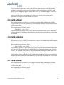
4.9.10 SERVo:TRACe
This command sets the period in seconds for the debug trace. Debug trace data can be used with
Ulrich Bangert’s “Plotter” utility to show UTC tracking versus time etc.
This command has the following format:
SERVo:TRACe <int > [0,255]
An example output is described here:
08-07-31 373815 60685 -32.08 -2.22E-11 14 10 6 0x54
[date][1PPS Count][Fine DAC][UTC offset ns][Frequency Error Estimate][Sats Visible][Sats
Tracked][Lock State][Health Status]
Please see the SYNChronization? command for detailed information on how to decode the health
status indicator values.
Note: health status information is available with firmware versions 0.913 and later.
The Lock State variable indicates one of the following states:
Value
State
0
OCXO warmup
1
Holdover
2
Locking (OCXO training)
4
[Value not defined]
5
Holdover, but still phase locked (stays in this state for about 100s after GPS lock
is lost)
6
Locked, and GPS active
4.9.11 SERVo?
This command returns the result of the following queries:
SERVo:COARSeDac?
SERVo:DACGain?
SERVo: EFCScale?
SERVo:EFCDamping?
SERVo:SLOPe?
SERVo:TEMPCOmpensation?
38
© 2011 Jackson Labs Technologies, Inc.
GPSTCXO Eval Board User Manual
SERVo:AGINGcompensation?
SERVo:PHASECOrrection?
SERVo:1PPSoffset?
SERVo:TRACe?
© 2011 Jackson Labs Technologies, Inc.
39
GPSTCXO Eval Board User Manual
40
© 2011 Jackson Labs Technologies, Inc.
FireFly-1A User Manual
5
Certification and
Warranty
5.0.1 Warranty
This Jackson Labs Technologies, Inc. hardware product is delivered for evaluation purposes only and
not for resale or for commercial purposes, and no warranty of any kind is given. Defective units may
be exchanged on a case-by-case basis, and upon the discretion of Jackson Labs Technologies, Inc.
5.0.2 Limitation of Warranty
[EXCEPT AS EXPRESSLY PROVIDED HEREIN,] JACKSON LABS MAKES NO
WARRANTIES OF ANY KIND WHETHER EXPRESS, IMPLIED, STATUTORY OR
OTHERWISE, AND SPECIFICALLY DISCLAIM ALL IMPLIED WARRANTIES,
INCLUDING ANY WARRANTIES OF MERCHANTABILITY, FITNESS FOR A
PARTICULAR PURPOSE, QUIET ENJOYMENT AND NON INFRINGEMENT OF THIRD
PARTY RIGHTS, TO THE MAXIMUM EXTENT PERMITTED BY APPLICABLE LAW.
The foregoing warranty shall not apply to Customer-supplied software or interfacing, unauthorized
modification or misuse, opening of the instruments enclosure or removal of the instruments panels,
operation outside of the environmental or electrical specifications for the product, or improper site
preparation and maintenance. JACKSON LABS TECHNOLOGIES, INC. SPECIFICALLY
DISCLAIMS THE IMPLIED WARRANTIES OF MERCHANTABILITY AND FITNESS
FOR A PARTICULAR PURPOSE. No license, express or implied, by estoppel or otherwise, to
any intellectual property rights is granted by this document. Jackson Labs Technologies, Inc.
products are not intended for use in medical, life saving, or life sustaining applications.
5.0.3 Exclusive Remedies
THE REMEDIES PROVIDED HEREIN ARE THE CUSTOMER'S SOLE AND EXCLUSIVE
REMEDIES. JACKSON LABS TECHNOLOGIES, INC. SHALL NOT BE LIABLE FOR
ANY DIRECT, INDIRECT, SPECIAL, INCIDENTAL, OR CONSEQUENTIAL DAMAGES,
WHETHER BASED ON CONTRACT, TORT, OR ANY OTHER LEGAL THEORY.
© 2011 Jackson Labs Technologies, Inc.
41
FireFly-1A User Manual
42
© 2011 Jackson Labs Technologies, Inc.