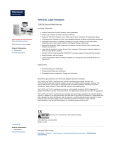
1
User Manual
CSA7000 Series
Serial Mask Testing &
Serial Pattern Trigger
TDS6000 & TDS7000 Series
Option SM Serial Mask Testing
Option ST Serial Pattern Trigger
071-1035-03
This document applies to firmware version 2.2
and above.
www.tektronix.com
Copyright © Tektronix, Inc. All rights reserved.
Tektronix products are covered by U.S. and foreign patents, issued and pending. Information in this publication supercedes
that in all previously published material. Specifications and price change privileges reserved.
Tektronix, Inc., P.O. Box 500, Beaverton, OR 97077-0001
TEKTRONIX and TEK are registered trademarks of Tektronix, Inc.
Table of Contents
Preface . . . . . . . . . . . . . . . . . . . . . . . . . . . . . . . . . . . . . . . . . . . . . . . . . . .
iii
Manual Structure . . . . . . . . . . . . . . . . . . . . . . . . . . . . . . . . . . . . . . . . . . . . . . . .
Related Manuals . . . . . . . . . . . . . . . . . . . . . . . . . . . . . . . . . . . . . . . . . . . . . . . . .
Contacting Tektronix . . . . . . . . . . . . . . . . . . . . . . . . . . . . . . . . . . . . . . . . . . . . .
iii
iii
v
Getting Started . . . . . . . . . . . . . . . . . . . . . . . . . . . . . . . . . . . . . . . . . . . .
1
Product Description . . . . . . . . . . . . . . . . . . . . . . . . . . . . . . . . . . . . . . . . . . . . . .
Installing Optional Serial Mask Testing and Serial Pattern Trigger Functions
on TDS6000 and TDS7000 Series Instruments . . . . . . . . . . . . . . . . . . . . .
1
Operating Basics . . . . . . . . . . . . . . . . . . . . . . . . . . . . . . . . . . . . . . . . . .
5
Serial Mask Testing Functions . . . . . . . . . . . . . . . . . . . . . . . . . . . . . . . . . . . . . .
Accessing Serial Pattern Trigger Functions . . . . . . . . . . . . . . . . . . . . . . . . . . . .
5
8
Reference . . . . . . . . . . . . . . . . . . . . . . . . . . . . . . . . . . . . . . . . . . . . . . . . .
11
Mask Testing . . . . . . . . . . . . . . . . . . . . . . . . . . . . . . . . . . . . . . . . . . . . . . . . . . . .
Communication (Comm) Triggering . . . . . . . . . . . . . . . . . . . . . . . . . . . . . . . . .
Serial Pattern Trigger . . . . . . . . . . . . . . . . . . . . . . . . . . . . . . . . . . . . . . . . . . . . .
11
32
36
Appendix A: Supported Mask Types and Standards . . . . . . . . . . . .
Appendix B: Supported Communication Trigger
Codes and Standards . . . . . . . . . . . . . . . . . . . . . . . . . . . . . . . . . . .
Appendix C: Automatic Communication Signal Measurements . . .
41
Levels Used in Taking Eye Measurements . . . . . . . . . . . . . . . . . . . . . . . . . . . .
48
Index . . . . . . . . . . . . . . . . . . . . . . . . . . . . . . . . . . . . . . . . . . . . . . . . . . . .
51
Serial Mask Testing & Serial Pattern Trigger User Manual
3
45
47
i
Table of Contents
List of Figures
Figure 1: Masks control window . . . . . . . . . . . . . . . . . . . . . . . . . . . . .
Figure 2: Communication signal trigger functions . . . . . . . . . . . . . .
Figure 3: Communication measurement functions . . . . . . . . . . . . . .
Figure 4: Serial pattern trigger control window . . . . . . . . . . . . . . . . .
Figure 5: Eye-diagram and optical values . . . . . . . . . . . . . . . . . . . . . .
5
6
7
8
48
Table 1: Masks control window functions . . . . . . . . . . . . . . . . . . . . .
Table 2: Communication trigger functions . . . . . . . . . . . . . . . . . . . .
Table 3: Serial trigger functions . . . . . . . . . . . . . . . . . . . . . . . . . . . . .
Table 4: ITU-T masks . . . . . . . . . . . . . . . . . . . . . . . . . . . . . . . . . . . . . .
Table 5: ANSI T1.102 masks . . . . . . . . . . . . . . . . . . . . . . . . . . . . . . . .
Table 6: Ethernet masks . . . . . . . . . . . . . . . . . . . . . . . . . . . . . . . . . . . .
Table 7: SONET/SDH masks . . . . . . . . . . . . . . . . . . . . . . . . . . . . . . . .
Table 8: Fibre Channel masks . . . . . . . . . . . . . . . . . . . . . . . . . . . . . . .
Table 9: Fibre Channel Electrical masks . . . . . . . . . . . . . . . . . . . . . .
Table 10: InfiniBand masks . . . . . . . . . . . . . . . . . . . . . . . . . . . . . . . . .
Table 11: Serial ATA masks . . . . . . . . . . . . . . . . . . . . . . . . . . . . . . . . .
Table 12: USB 1.1/2.0 masks . . . . . . . . . . . . . . . . . . . . . . . . . . . . . . . .
Table 13: 1394b masks . . . . . . . . . . . . . . . . . . . . . . . . . . . . . . . . . . . . .
Table 14: Rapid IO LP-LVDS masks . . . . . . . . . . . . . . . . . . . . . . . . .
Table 15: Rapid IO Serial masks . . . . . . . . . . . . . . . . . . . . . . . . . . . .
Table 16: IOF masks . . . . . . . . . . . . . . . . . . . . . . . . . . . . . . . . . . . . . . .
Table 17: PCI-Express masks . . . . . . . . . . . . . . . . . . . . . . . . . . . . . . .
Table 18: AMI trigger standards . . . . . . . . . . . . . . . . . . . . . . . . . . . . .
Table 19: B3ZS trigger standards . . . . . . . . . . . . . . . . . . . . . . . . . . . .
Table 20: B6ZS trigger standards . . . . . . . . . . . . . . . . . . . . . . . . . . . .
Table 21: B8ZS trigger standards . . . . . . . . . . . . . . . . . . . . . . . . . . . .
Table 22: CMI trigger standards . . . . . . . . . . . . . . . . . . . . . . . . . . . . .
Table 23: HDB3 trigger standards . . . . . . . . . . . . . . . . . . . . . . . . . . .
Table 24: MLT3 trigger standards . . . . . . . . . . . . . . . . . . . . . . . . . . .
Table 25: NRZ trigger standards . . . . . . . . . . . . . . . . . . . . . . . . . . . .
Table 26: Supported communications measurements and
their definition . . . . . . . . . . . . . . . . . . . . . . . . . . . . . . . . . . . . . . . .
5
6
8
41
41
41
42
42
42
42
42
43
43
43
43
44
44
45
45
45
45
46
46
46
46
List of Tables
ii
47
Serial Mask Testing & Serial Pattern Trigger User Manual
Preface
This is the user manual for Serial Mask Testing and Serial Pattern Trigger
functions. The user Mask functions, Mask Testing functions and Comm
measurements are standard on CSA7000 Series instruments, and both TDS6000
and TDS7000 Series instruments. All other functions mentioned in this
document are optional for TDS6000 and TDS7000 Series instruments. Serial
Pattern Trigger is not available on TDS7104 and TDS7054 instruments.
This manual:
H
Describes the capabilities of the Serial Mask Testing and Serial Pattern
Trigger functions, and how to install these functions on TDS6000 and
TDS7000 instruments
H
Explains how to access and operate the features
Manual Structure
This manual is organized into the following chapters:
H
Getting Started provides an overview of the Serial Mask Testing and Serial
Pattern Trigger functions, and shows you how to install these functions on
TDS6000 and TDS7000 instruments.
H
Operating Basics describes how to access the functions using the front panel
and the instrument graphical user interface.
H
Reference provides detailed steps for doing the most common Serial Mask
Testing and Serial Pattern Trigger tasks.
Related Manuals
The following table lists other documents that support the operation and service
of the CSA7000, TDS6000, and TDS7000 Series instruments. The part numbers
of these documents are listed in the Accessories section of your instrument user
manual.
Serial Mask Testing & Serial Pattern Trigger User Manual
iii
Preface
Manual name
Description
Online Help
An online help system that is integrated with the User Interface application that ships
with the CSA7000, TDS7000, and TDS6000 instruments
References
A quick reference to the major features of the instrument and how they operate
User Manual1
The user manual for the CSA7000, TDS7000, and TDS6000 instruments
Programmer Online Guide
An alphabetical listing of the programming commands and other information related to
controlling the instrument over the GPIB and TekVISA interfaces
Service Manual
A description of how to service the instrument to the module level. This optional
manual must be ordered separately
1
iv
You can insert this user manual behind the Appendices section of your instrument user manual.
Serial Mask Testing & Serial Pattern Trigger User Manual
Preface
Contacting Tektronix
Phone
1-800-833-9200*
Address
Tektronix, Inc.
Department or name (if known)
14200 SW Karl Braun Drive
P.O. Box 500
Beaverton, OR 97077
USA
Web site
www.tektronix.com
Sales support
1-800-833-9200, select option 1*
Service support
1-800-833-9200, select option 2*
Technical support
Email: [email protected]
1-800-833-9200, select option 3*
6:00 a.m. - 5:00 p.m. Pacific time
*
This phone number is toll free in North America. After office hours, please leave a
voice mail message.
Outside North America, contact a Tektronix sales office or distributor; see the
Tektronix web site for a list of offices.
Serial Mask Testing & Serial Pattern Trigger User Manual
v
Preface
vi
Serial Mask Testing & Serial Pattern Trigger User Manual
Getting Started
This section of the user manual provides a high-level description of the Serial
Mask Testing and Serial Triggering functions. The user Mask functions, Mask
Testing functions and Comm measurements are standard with the CSA7000
Series instruments and both TDS7000 Series Digital Phosphor Oscilloscopes and
TDS6000 Series Digital Sampling Oscilloscopes. All other functions mentioned
in this document are optional for TDS6000 and TDS7000 Series oscilloscopes.
Serial Pattern Trigger is not available on TDS7104 and TDS7054 instruments.
This section also describes how to install Serial Mask Testing and Serial
Triggering functions on TDS6000 and TDS7000 Series instruments.
Product Description
The following text is an overview of the Serial Mask Testing and Serial
Triggering features.
Serial Mask Testing
The Serial Mask Testing feature provides optical and electrical mask testing,
communication triggering, and automatic communication signal measurements.
Mask testing consists of two tasks: signal violation detection and pass/fail
testing. Signal violation detection lets you test communications signals for time
or amplitude violations against a predefined mask. Each mask consists of one or
more polygonal regions called segments. The signal waveform data should stay
outside of the segments defined by the mask. Any signal data that occurs inside a
mask segment is called a mask segment violation or “hit.”
You can select from any of the included standard telecommunications masks, or
you can define your own custom masks. Selecting a mask automatically sets the
instrument communications triggers to properly display most communication
signals in the mask.
Pass/Fail testing defines the mask testing parameters, including the number of
waveforms to test, how many mask hits are allowed before failing a test, setting
a mask margin tolerance value, and what action to perform at the completion of a
test.
Communication triggering enables you to trigger on and display waveforms for
industry-standard communications signals. Appendix B lists the supported
standards on which you can trigger.
Automatic communication signal measurements enable you to make automatic
measurements on communications signals. Appendix C lists the available
measurements.
Serial Mask Testing & Serial Pattern Trigger User Manual
1
Getting Started
The Serial Mask Testing key features are:
H
Predefined masks for testing or triggering on industry-standard signals, such
as ITU--T G.703, ANSI T1.102, Fibre Channel, Ethernet, InfiniBand,
SONET, Serial ATA, USB, IEEE 1394b, and their subsets
H
On CSA7000 instruments, optical mask standards have calibrated digital
filters, enabling operation as an optical reference receiver
H
Autoset, which quickly adjusts the instrument vertical and horizontal
parameters to display a waveform in a mask
H
Autofit, which positions the signal on each acquisition to minimize mask
segment hits
H
Mask margins, which allow you to adjust the default mask margin tolerances
H
Pass/Fail testing to continuously test a specified number of waveforms
against a mask
H
A mask editor for creating, saving, and recalling user-defined masks
H
Waveform database technology to do mask testing based on waveforms
accumulated in a database, rather than a single waveform stored in acquisition memory
H
Communications triggers to trigger the instrument on industry-standard
communications signals
H
Automatic measurements on communications signals
H
Clock recovery from the serial data stream (except for TDS7104 and
TDS7054 instruments)
NOTE. If a standard or function listed in this manual is not available on your
instrument, it is because the configuration or bandwidth of your instrument
cannot test that standard.
The CSA7000 Series instruments, when used with the O/E Electrical Out-to-CH1
Input Adapter (013--0327--xx), are calibrated optical reference receivers with
digital filtering, enabling you to do mask standard compliance testing.
Although the TDS6000 and TDS7000 Series instruments are not calibrated
optical reference receivers, you can use them with mask testing to evaluate
general optical signal characteristics and waveshape, using an external O/E
converter.
2
Serial Mask Testing & Serial Pattern Trigger User Manual
Getting Started
Serial Pattern Trigger
Serial Pattern Trigger lets you define a serial data pattern on which to trigger the
instrument (not available on TDS7104 and TDS7054 instruments).
The Serial Pattern Trigger key features are:
H
User-defined serial data pattern of up to 32 bits on NRZ data streams up to
1.25 GBaud
H
Clock recovery from the serial data stream
Installing Optional Serial Mask Testing and Serial Pattern Trigger Functions
on TDS6000 and TDS7000 Series Instruments
To enable the optional Serial Mask Testing and/or Serial Triggering functions on
TDS6000 and TDS7000 instruments, you must have a valid Option Installation
Key. Do the following steps:
1. From the oscilloscope menu bar, touch the Utilities menu, select Option
Installation, and then touch Continue.
2. Enter the authorization key using the instrument keyboard.
3. Touch Continue.
4. Reboot your instrument to enable the new option(s).
5. Attach the option configuration label(s) on the rear panel of the instrument to
indicate that the option(s) is installed on this instrument.
Serial Mask Testing & Serial Pattern Trigger User Manual
3
Getting Started
4
Serial Mask Testing & Serial Pattern Trigger User Manual
Operating Basics
This chapter describes how to access the Serial Mask Testing and Serial Pattern
Triggering features, and provides a brief description of each function’s settings.
See the Reference section in this manual for detailed instructions on using the
Serial Mask Testing and Serial Pattern Triggering functions.
Serial Mask Testing Functions
Serial Mask Testing provides three sets of functions: optical and electrical serial
mask testing, communications triggering, and automatic communication signal
measurements. This section describes how to access these functions.
Accessing Serial Mask
Testing Functions
To access the Serial Mask Test functions, touch the Masks tool bar button. The
instrument displays the Masks control window, as shown in Figure 1.
Figure 1: Masks control window
Table 1 describes the Masks control window tab functions. Refer to the
Reference chapter beginning on page 11 of this manual, as well as the online
help, for more information about these functions.
Table 1: Masks control window functions
Tab
Function
Mask
Set the mask type, communications standard, polarity, mask on/off, and autofit/autoset alignment
parameters
Source
Set the input waveform source
Tolerance
Set the mask margin tolerance values
Serial Mask Testing & Serial Pattern Trigger User Manual
5
Operating Basics
Table 1: Masks control window functions (cont.)
Tab
Function
Pass/Fail Setup
Set the mask test pass/fail parameters
Pass/Fail Results
Display the pass/fail test results
Accessing Serial Mask
Testing Communications
Trigger Functions
To access the Serial Mask Testing communication trigger functions, do the
following steps:
1. Touch the Trig tool bar button. The instrument displays the Trigger control
window.
2. Select the A Event tab.
3. Touch Comm in Trigger Type. The instrument displays the communication
signal trigger functions, as shown in Figure 2.
Figure 2: Communication signal trigger functions
Table 2 describes the communication trigger functions. Refer to the Reference
chapter beginning on page 11 of this manual, as well as the online help, for more
information about these functions.
Table 2: Communication trigger functions
Menu
Function
Source
Sets the waveform data source (Ch1-Ch4)
Type
Sets the waveform source type (Data, Clock, or Recovered Clock); the recovered clock function is not
available on the TDS7104 or the TDS7054, and is only available for NRZ coded signals
Polarity
Sets the edge (positive or negative) on which to trigger; this function is only available when Type is set to
Clock
6
Serial Mask Testing & Serial Pattern Trigger User Manual
Operating Basics
Table 2: Communication trigger functions (cont.)
Menu
Function
Coding
Sets the communications code type from a drop-- down menu (AMI, BZ3S, B6ZS, B8ZS, CMI, HDB3,
MLT3, NRZ)
Standard
Sets the signal standard for the selected code from a drop-- down menu
Bit Rate
Sets or displays the bit rate for the selected standard; if you change the default bit rate, the signal
standard changes to Custom
Comm Trigger
Upper/Lower Level
Sets the source signal threshold levels for the selected code; this function displays a single level field or
upper/lower level fields depending on the selected code and standard
Pulse Form
Sets the comm signal pulse format on which to trigger; this function is displayed when required by a
selected standard
Accessing Serial Mask
Testing Automatic
Measurement Functions
Serial Mask Testing uses the built--in, automatic communications measurements.
To access the communications signal automatic measurements, do the following
steps:
1. Touch the Meas tool bar button. The instrument displays the Measurement
control window.
2. Select the Comm tab. The instrument displays the communication measurement functions, as shown in Figure 3.
Figure 3: Communication measurement functions
Refer to the user manual for your instrument for information on setting up and
taking automatic measurements. Refer to Appendix C of this manual for a list
and description of the communication measurements.
Serial Mask Testing & Serial Pattern Trigger User Manual
7
Operating Basics
Accessing Serial Pattern Trigger Functions
To access the Serial Pattern Trigger functions, do the following steps:
1. Touch the Trig tool bar button. The instrument displays the Trigger control
window.
2. Select the A Event tab.
3. Touch Serial in the Trigger Type field. The instrument displays the serial
pattern trigger functions, as shown in Figure 4.
Figure 4: Serial pattern trigger control window
Table 3 describes the Serial Pattern Trigger functions. Refer to the Reference
chapter beginning on page 11 of this manual, as well as the online help, for more
information about these functions.
Table 3: Serial trigger functions
Menu
Function
Data Src
Sets the serial trigger waveform data source (Ch1-Ch4)
Clk Src
Sets the serial trigger clock source (Ch1-Ch4, Recovered Clock); the recovered clock function is not
available on the TDS7104 or the TDS7054, and is only available for NRZ coded signals on the TDS6000
and TDS7000 Series instruments
Clk Polarity
Sets the source waveform polarity (positive or negative); this function is available only when Clk Src is set
to a different value than Data Src
Coding
Shows the serial trigger communications code type, which is always NRZ
Standard
Sets the serial trigger signal standard
Bit Rate
Sets or displays the bit rate for the selected standard
Data Level
Clk Level
Sets the data and clock source threshold levels for the selected code
8
Serial Mask Testing & Serial Pattern Trigger User Manual
Operating Basics
Table 3: Serial trigger functions (cont.)
Menu
Function
Editor
Opens the serial pattern data editor which lets you define the serial pattern on which to trigger
Format
Displays the serial trigger pattern data in binary or hexadecimal format
Serial Mask Testing & Serial Pattern Trigger User Manual
9
Operating Basics
10
Serial Mask Testing & Serial Pattern Trigger User Manual
Reference
This chapter contains instructions for performing the following tasks:
H
Mask Testing (starting on this page) describes how to set up and run mask
tests, as well as how to create, edit, and save user masks.
H
Communication (Comm) Triggering (page 32) describes how to trigger on
industry-standard communication signals, and provides information on the
recovered clock (R Clk) feature.
H
Serial Pattern Trigger (page 36) describes how to trigger on user-defined
serial data.
Mask Testing
Mask testing sets the instrument to test industry-standard communications
signals against defined masks to verify the timing, amplitude, and waveform
shape of the signal. This section provides step-by-step instructions on how to
access and operate the mask test features.
The mask testing instructions cover the following subjects:
H
Mask test setup
H
Running a mask test
H
Creating a user mask from a defined mask
H
Saving a user mask to disk
H
Recalling a user mask from disk
H
Editing a user mask
H
Creating a new user mask
H
Mask testing key points (general and optical)
Serial Mask Testing & Serial Pattern Trigger User Manual
11
Reference
Mask Test Setup
Overview
To set the instrument to perform mask tests, do the following procedure.
To mask test a waveform
Prerequisites 1.
Access the 2.
Mask Setup
window
Related control elements and resources
Connect the instrument to the source signal, or save the
source signal to a math or reference waveform memory
location.
From the button bar, touch Masks.
The instrument displays the Mask control window.
Select a mask 3.
test signal
source
12
Select the Source tab and then the channel, math, or
reference tab and then select the waveform source to
use as the mask test source. You can mask test one
waveform at a time.
Serial Mask Testing & Serial Pattern Trigger User Manual
Reference
Overview
To mask test a waveform (cont.)
Select the mask 4.
type
Related control elements and resources
To specify the mask Type, select the Masks tab. Touch
the appropriate button in the Type field. Touch the More
button to display further selections.
The window lists mask types and standards that are
available on your instrument, which depends on the
bandwidth and configuration of your instrument.
Selecting a mask type and standard adjusts the
instrument horizontal, vertical, and trigger settings to
those appropriate for displaying a waveform of the
specified type. If the signal is not within the mask, touch
the Autoset button to center the waveform in a mask. If
Autoset did not align the signal in the mask, adjust the
instrument vertical and horizontal controls.
If you touch the Autoset button and the Autoset Undo
preference is On, the instrument will display an Autoset
Undo window. Touch the Undo button to return to the
previous settings, or touch the Close button to remove
the window.
Select the mask 5.
standard
To specify the mask standard, select a standard from the
drop-- down list.
(CSA7000 Series only) Optical mask type/standard
combinations also display an optical Bessel-Thompson
Filter button that lets you turn on or off the fourth-order
Bessel-Thompson frequency filter (default is On). When
the filter is On, the CSA7000 series is an Optical
Reference Receiver.
CAUTION. Do not exceed the maximum nondestructive
optical input specified in your instrument user manual.
Verify that your optical input signal is within the linear
operating range of the optical-to-electrical converter and
the optical reference receiver.
Serial Mask Testing & Serial Pattern Trigger User Manual
13
Reference
Overview
To mask test a waveform (cont.)
Select 6.
display
parameters
Related control elements and resources
In the Masks tab, touch the Display button to toggle
mask display on or off. The mask must be turned on to
do mask testing.
7.
Touch the Hit Count button to turn on or off hit counting.
The hit count is shown in the Pass/Fail Results tab.
8.
Touch the Display Config button to set mask hit
highlighting and to lock the mask to the waveform. Lock
Mask to Waveform resizes the mask to reflect changes
in the horizontal or vertical settings of the instrument.
This control is also on the main mask setup window.
Autoset the 9.
signal
In the Masks tab, touch the Autoset button to have the
instrument automatically adjust instrument settings to
align the waveform to the mask based on the
characteristics of the input signal. Autoset is done on the
first waveform acquired after touching the Autoset
button.
If the Autoset Undo preference is On, the instrument will
display an Autoset Undo window. Touch the Undo button
to return to the previous settings, or touch the Close
button to remove the window.
The Autoset Config button opens a configuration
window that lets you set the vertical, horizontal, and
trigger autoset parameters, activate autofit or autoset,
choose the autoset mode, return to the default autoset
configuration, or return to the Mask Setup control
window.
On CSA7000 series instruments when using the O/E
Electrical Out-to-CH1 Input adapter, autoset defaults to
CH 1, and the instrument will ignore the other channels.
14
Serial Mask Testing & Serial Pattern Trigger User Manual
Reference
Overview
To mask test a waveform (cont.)
Related control elements and resources
Enable and set 10. In the Masks tab, touch the Autofit button to enable the
waveform
waveform autofit function. Autofit checks each waveform
autofit
for any mask hits. If there are hits, autofit repositions the
parameters
waveform to minimize hits. The number of hits reported
is the number after autofit has minimized hits.
The autofit Config button lets you set the autofit
maximum waveform repositioning parameters (as a
percentage of the horizontal and vertical divisions),
return to default settings, or return to the Mask Setup
control window. Use the keypad to change the vertical or
horizontal autofit parameters.
11. Touch the Masks button to return to the Mask control
window.
Set mask test 12. Touch the Masks Setup window Tolerance tab to set the
tolerance
percentage of margin used in the mask test. Use the
margins
control knob, keypad, pop-up keypad, or up and down
arrow buttons to enter the mask margin tolerance
percentage. The range of values is - 50% to 50%.
Margin tolerance settings greater than 0% expand the
size of the segments, making the mask test harder to
pass; margin tolerance settings less than 0% (negative
percent) reduces the size of the segments, making the
mask test easier to pass.
Serial Mask Testing & Serial Pattern Trigger User Manual
15
Reference
Overview
To mask test a waveform (cont.)
Related control elements and resources
Set mask test 13. Select the Pass/Fail Setup tab of the Masks control
pass and fail
window.
parameters
14. Use the control knob, keypad, or pop-up keypad to enter
the number of waveforms to test (number of samples in
some modes), the failure threshold (the number of
waveforms that must fail to fail the test), and the delay
time (the time from when mask test starts to when the
instrument begins sampling).
15. Use the Failure field buttons to set what the instrument
does when a mask test fails; have the instrument beep
(BEEP), send an SRQ out on the GPIB bus (SRQ), send
a trigger pulse out on the AUX OUT connector (AUX
Out), stop signal acquisition immediately (Stop Acq),
and/or print the instrument screen image to a printer
(Print).
16. Touching the More button displays more failure
functions. Save Wfm saves the the waveform data of
the first waveform that causes the test to fail to a .wfm
file. Log Date saves time, date, and basic test
information of the first waveform that causes the test to
fail to an ASCII text (.txt) file.
Both files are saved to the location specified by the Path
button. The file name format is YYMMDD-- HHMMSS,
where YY is year, MM is month, DD is day, HH is hour,
MM is minutes, and SS is seconds.
17. Use the Completion field buttons to set what the
instrument does at the completion of a mask test.
16
Serial Mask Testing & Serial Pattern Trigger User Manual
Reference
Overview
To mask test a waveform (cont.)
Related control elements and resources
Set test pass 18. Use the Polarity buttons to set mask and waveform
and fail
polarity. Positive tests the positive waveform pulses.
parameters
Negative inverts the mask and tests the negative
(cont.)
waveform pulses. Both tests the first half of the tested
waveforms in positive polarity mode, then tests the
remaining waveforms in negative polarity mode.
19. Toggle the Repeat button to On to set the instrument to
repeat (continue) mask testing on the completion of
each test.
Serial Mask Testing & Serial Pattern Trigger User Manual
17
Reference
Running a Mask Test
Overview
To start and stop mask tests, do the following procedure.
Running a mask test
Prerequisites 1.
Start the mask 2.
pass/fail test
3.
Control elements and resources
You must have set up the instrument to perform mask
testing as described in Mask Test Setup on page 12.
From the button bar, touch Masks and select the
Pass/Fail Results tab. The instrument opens the
Pass/Fail Results control window.
Touch the Pass/Fail Test On/Off button to turn on mask
pass/fail testing. You can touch Reset prior to running
tests to clear the Pass/Fail Test Summary fields.
You can also use the Pass/Fail Test button in the
Pass/Fail Setup control window.
The instrument begins mask testing and displays the
test summary information in the Pass/Fail Test Summary
fields. If a mask has more than three segments, the
window displays a horizontal scroll bar below the Hits
per Segment field that lets you scroll the field to view
other segment hit data.
Stop the mask 4.
pass/fail test
18
Touch the Pass/Fail test button to turn off mask pass/fail
testing. Testing will also stop when the testing meets the
parameters in the Pass/Fail Setup control window.
Serial Mask Testing & Serial Pattern Trigger User Manual
Reference
Creating a User Mask from
a Defined Mask
Overview
Refer to Mask Key Points on page 30 before creating or editing a mask. To create
a user mask from a defined mask, do the following procedure.
Creating a user mask from a defined mask
Access the 1.
mask setup
window
Control elements and resources
From the button bar, touch Masks and select the
Masks tab.
The instrument displays the Mask control window.
Select the mask 2.
type and
standard
3.
Touch the appropriate button in the Type field to select a
mask type. Touch the More button to display further
selections.
Select a standard from the drop-- down list.
The control window lists mask types and standards that
are available on your instrument, which depend on the
bandwidth and configuration of your instrument.
Serial Mask Testing & Serial Pattern Trigger User Manual
19
Reference
Overview
Creating a user mask from a defined mask (cont.)
Copy the cur- 4.
rent mask
Touch the User Mask button.
5.
Touch the Copy Current Mask to User Mask button. The
instrument copies the current mask to the user mask
memory.
Edit the user
mask
6.
Refer to Editing a User Mask on page 21.
Save the user
mask to disk
7.
Refer to Saving a User Mask to Disk on page 23. You do
not need to save the edited user mask to disk, as the
instrument retains the current user mask in nonvolatile
memory. However, if you plan on creating a number of
user masks, you will need to store the user masks on
disk, as the instrument can load one user mask at a
time.
20
Control elements and resources
Serial Mask Testing & Serial Pattern Trigger User Manual
Reference
Editing a User Mask
Overview
To edit a user mask, do the following procedure.
Editing a user mask
Access the 1.
mask edit
window
2.
From the button bar, touch Masks and select the
Masks tab.
3.
Touch the Edit User Mask button. The instrument
displays the Mask Edit control window.
Control elements and resources
Touch the User Mask button.
Enable the 4.
mask edit
controls
Touch the Controls button to open the mask edit controls
window on the right side of the screen. This provides the
maximum area to display the mask, making editing
easier.
Select a 5.
segment
Touch the Segment field and use the arrow buttons,
multipurpose knob, or keypad to select a segment to
edit. The selected (active) segment is highlighted in red.
Each mask can have up to 16 segments.
Select a 6.
vertex
Touch the Vertex field and use the arrow buttons,
multipurpose knob, or keypad to select the vertex to
edit. The active vertex is indicated with an X on the
template segment. Each segment can have up to 50
vertices.
Serial Mask Testing & Serial Pattern Trigger User Manual
21
Reference
Overview
Editing a user mask (cont.)
Move a 7.
vertex
8.
Add or delete a 9.
vertex
Control elements and resources
Touch the Horizontal field and use the multipurpose
knob or keypad to change the selected vertex horizontal
position.
Touch the Vertical field and use the multipurpose knob
or keypad to change the selected vertex vertical
position.
To add a vertex, select the closest vertex that is
clockwise from where you want to place a new vertex.
Touch Add to add a vertex midway between the selected
vertex and the next counter-clockwise vertex.
10. To delete a vertex, enter or select the vertex number.
Then touch Delete to delete the selected vertex. The
remaining vertices located counter-clockwise from the
deleted vertex are renumbered.
Save the user 11. Refer to Saving a User Mask to Disk on page 23.
mask to disk
22
Serial Mask Testing & Serial Pattern Trigger User Manual
Reference
Saving a User Mask to
Disk
Overview
To save a mask to a folder on the instrument disk, do the following procedure.
Saving a user mask to disk
Access the 1.
Mask Setup
window
2.
3.
Save the user 4.
mask to disk
Control elements and resources
From the button bar, touch Masks and select the Masks
tab.
Touch the User Mask button.
Touch the Edit User Mask button. The instrument
displays the Mask Edit control window.
Touch the Mask Save button.
The instrument opens the Save Mask As dialog. The
default save location is in the TekScope/Masks folder.
5.
Enter the mask name in the File Name field. The default
save type is User Mask Files (*.msk).
6.
Touch Save to save the mask to disk.
Serial Mask Testing & Serial Pattern Trigger User Manual
23
Reference
Recalling a User Mask
From Disk
Overview
To recall a mask that was stored on disk, do the following procedure.
Recalling a user mask
Access the 1.
Mask Setup
window
2.
3.
Recall the user 4.
mask from disk
Control elements and resources
From the button bar, touch Masks and select the Masks
tab.
Touch the User Mask button.
Touch the Edit User Mask button. The instrument
displays the Mask Edit control window.
Touch the Mask Recall button.
The instrument opens the Recall Mask dialog. The
default recall location is the TekScope/Masks folder. If
the mask files are in another folder, use the navigation
controls to access the appropriate folder.
24
5.
Select the mask name.
6.
Touch Recall to load the user mask into user mask
memory on the instrument.
Serial Mask Testing & Serial Pattern Trigger User Manual
Reference
Creating a New User Mask
Overview
To create a new user mask that is not based on an existing mask, do the
following procedure.
Creating a new mask
Set instrument 1.
settings
Control elements and resources
Use the communications trigger features to trigger the
instrument on a signal. The instrument saves these
settings with the mask information.
See the instrument user manual for
information on displaying waveforms.
Create an empty 2.
user mask
From the button bar, touch Masks and select the
Masks tab.
3.
Touch the User Mask button.
4.
Touch the mask standard field to display the drop-down
list.
5.
Select None from the list.
6.
Touch the Copy Current Mask to User Mask button. If
you are asked if you want to overwrite the current user
mask, touch the Yes button.
7.
Touch the Edit User Mask button. The instrument
displays the Mask Edit control window.
Serial Mask Testing & Serial Pattern Trigger User Manual
25
Reference
Overview
Creating a new mask (cont.)
Create and edit 8.
new mask
segments
9.
Control elements and resources
Touch the Edit User Mask button to display the user
mask edit functions.
Touch the Segment field and use the arrow buttons,
multipurpose knob, or keypad to enter or select
segment 1.
10. Touch the Vertex Add button. The instrument draws the
default new segment shape, a triangle.
11. Use the instructions in Editing a User Mask, starting at
step 5 on page 21, to edit a segment.
12. Repeat steps 9 through 11, selecting an unused and
sequential segment number, to create and edit more
segments.
Save the user
mask to disk
26
13. Refer to Saving a User Mask to Disk on page 23.
Serial Mask Testing & Serial Pattern Trigger User Manual
Reference
Mask Testing Example
Overview
The following procedure is an example of setting up the instrument to perform
mask testing on a DS1A signal. This example uses a DS1A signal and a
CSA7000 Instrument, but the example can easily be modified for other
communications signals and other instruments.
Creating a new mask
Install the test 1.
hookup
Control elements and resources
Connect your DS1A signal to CH 1 through suitable
cables, probes, or adapters.
CSA7000 Instrument
Signal Source
Output
2.
Set instrument 3.
settings
4.
Press DEFAULT SETUP.
From the button bar, touch Masks and select the
Masks tab.
Touch the ANSI T1.102 button.
If not using an DS1A signal, touch the button
appropriate for the signal that you are using.
5.
Touch the mask standard field to display the drop-down
list.
6.
Select DS1A (2.048 Mb/s) from the list (if not using a
DS1A signal, select the standard appropriate for the
signal that you are using).
The mask is displayed, but may not be aligned with the
signal.
Serial Mask Testing & Serial Pattern Trigger User Manual
27
Reference
Overview
Creating a new mask (cont.)
Align the mask 7.
and the signal
Control elements and resources
To align the signal with the mask, touch the Alignment
Autoset button.
The signal is aligned with the mask. If you need to
minimize the number of mask hits on each acquisition,
touch Autofit.
This display assumes that the autoset undo preference
is off or that you touch Close to close the Autoset Undo
control window.
Select the 8.
source
Change the 9.
tolerance
28
In this example, we are using the default source, CH 1.
Set the Mask Margin Tolerance to the percentage of
margin used in the mask test (this example uses the
default OFF):
H
OFF to test the signal to the selected mask
standard
H
Settings greater than 0% to expand the size of the
mask segments, making the test harder to pass
H
Settings less than 0% to reduce the size of the
mask segments, making the test easier to pass
Serial Mask Testing & Serial Pattern Trigger User Manual
Reference
Overview
Creating a new mask (cont.)
Control elements and resources
Setup pass/fail 10. Select the pass/fail test controls (this example uses the
testing
defaults except Pass/Fail Test Repeat is selected):
H
The number of samples or waveforms to test, the
minimum number of waveforms to test, and the
delay before the test begins
H
Notifications/actions when the test fails or
completes
H
Polarity of the signal to test
H
Start the test and cause the test to repeat
View the test 11. View the results of the pass/fail test (in this example
results
there have been no hits, and the current test is passing):
H
Pass/Fail Test Summary displays the number of
samples/waveforms tested, the total number of hits
(failures), and settings that you selected for the test
H
Hits per segment displays the number of hits in
each segment of the mask
H
Pass/Fail Test allows you to reset the test and to
turn the test on and off
Triggers set 12. When you turn on masks, the instrument automatically
automatically
sets up the triggers. To see the trigger settings used by
this example, do the following step:
From the button bar, touch Trig. The instrument selected
Comm triggers, the Ch 1 source, HDB3 coding, the Data
type, and the DS1A standard, and set the bit rate and
pulse form.
For more 13. For additional information on setting up and using serial
information
mask testing, refer to other sections of this user manual
and the instrument online help.
Serial Mask Testing & Serial Pattern Trigger User Manual
29
Reference
Mask Key Points
There are a number of mask test key points to be aware of prior to using, editing,
or creating a mask.
Mask Testing. Only one mask standard is active at any time. If you have a mask
selected/enabled and then select a new mask, the new mask replaces the previous
mask. You cannot test to multiple standards simultaneously.
Autofit and Persistence Interaction. The Autofit function moves the waveform
vertically and horizontally in a mask to reduce the number of segment hits within
a mask. If persistence is set to infinite or variable, each Autofit waveform
movement clears existing persistence data. If Autofit makes frequent waveform
movements, there may be little or no displayed waveform persistence data.
Segments and Mask Hits. Each mask can have a maximum of 16 segments.
Segments can overlap. The number of mask hits is the sum of all hits in all
segments, regardless of whether or not segments overlap. For example, if a
waveform crosses over an area where two segments overlap, both segments will
count the waveform hit.
Vertices. Each segment can have a maximum of 50 vertices. Vertices are
numbered counterclockwise, with vertex one generally located at the bottom left
of each segment. The active (selected) vertex is indicated by an X. The instrument automatically assigns numbers to vertices during mask creation or editing.
Mask Margin Tolerance. Mask margin tolerance moves the mask segment
boundaries by the specified percentage. Negative margins reduce the size of the
segment, making it easier to pass a mask test. If a user defined mask has more
than three segments, turning on mask margins generates an error message.
Turning mask margin tolerance off redraws the mask segment margins to their
default values, but leaves the numeric value as it is, allowing you to quickly
toggle between default and user-set margin values.
30
Serial Mask Testing & Serial Pattern Trigger User Manual
Reference
Standards and Bandwidth. When the instrument system bandwidth (which
includes the instrument, attached probes, and/or cabling) falls into the range of
1.5 to 1.8 (0.8 for optical signals) times the data signal bit rate, the third
harmonic of the data signal is significantly attenuated. The instrument displays
useful qualitative information, but quantitative rise-time measurements under
these conditions may not be accurate.
For example, a 1394b standard signal at the S800b rate has a bit rate of
983.0 Mb/s. 1.5 to 1.8 times this value is a range of 1.47 to 1.77 GHz. Therefore,
you should not use a 1.5 GHz measurement system for making quantitative
rise-time measurements of this standard.
When just the instrument bandwidth falls within 1.5-1.8 (0.8 for optical signals)
times the bit rate of a selected mask standard, the instrument displays the
message “Consider system bandwidth when testing at this bit rate.” in the status
area above the graticule.
Optical Mask Testing
Key Points
(CSA7000 Series Only)
There are a number of optical mask test key points to be aware of prior to doing
optical mask testing on the CSA7000 Series instruments.
H
The CSA7000 Series instruments, when equipped with the O/E Electrical
Out-to-Ch1 Input Adapter, are calibrated optical reference receivers. This
means that the instrument optical to electrical converter and instrument input
channel have been tuned to have a fourth-order Bessel-Thompson response,
as well as the correct frequency response for each supported standard by use
of digital filters.
H
When the O/E Electrical Out-to-Ch1 Input Adapter is installed, you select an
optical mask, and the Bessel-Thompson filter mode is On, then only channel
1 is available. Trying to turn on any other channels, or perform certain
functions such as changing the acquisition mode, results in an error message.
Turning the Bessel-Thompson filter mode to off enables access to the other
instrument channels, though channel 1 is no longer in the calibrated ORR
mode.
H
Optical signal mask testing is available for Fibre Channel, InfiniBand,
SONET, 1394β, and 1G Ethernet standards.
H
If a listed standard is not available on your instrument, it is because the
bandwidth of your instrument is not high enough to test that standard.
H
You can use O/E Adapters on different CSA7000 instruments without
affecting the optical reference receiver calibration on an instrument.
H
CSA7000 Series instruments provides recovered clock and recovered data
signal outputs on the instrument front panel, as well as using the signals for
internal triggering.
Serial Mask Testing & Serial Pattern Trigger User Manual
31
Reference
Communication (Comm) Triggering
Communication (Comm) triggering sets the instrument to trigger on industry-standard communication signals. This section describes how to access and
operate the communication trigger features.
Communication Triggering
Overview
To set the instrument to trigger on communication signals, do the following
procedure.
Communication triggering
Access the 1.
trigger control
window
Related control elements and resources
From the button bar, touch Trig and select the
A Event trigger tab.
The instrument opens the Trigger Setup control window.
Select a com- 2.
munications
trigger
Touch the Comm button.
The instrument displays the Comm Trigger controls.
Select comm 3.
trigger source
32
Touch the Source button to select the signal source
channel. Select from channel 1 through channel 4.
Serial Mask Testing & Serial Pattern Trigger User Manual
Reference
Overview
Communication triggering (cont.)
Select comm 4.
trigger coding
and standard
Related control elements and resources
Touch the Coding button and select the appropriate
code type for your signal from the list. The code
selected determines which standards are available as
well as other parameters, such as trigger threshold and
pulse form.
5.
Touch the Standard button, and select the appropriate
signal standard from the list. The standard selected
determines the bit rate.
6.
The Bit Rate field shows the bit rate for the selected
standard. Touch the Bit Rate field, and use the
multipurpose knob or keypad to enter the serial data
stream bit rate for nonstandard bit rates.
Note. Changing the bit rate means the instrument is not
triggering in accordance with the standard. The
Standard type changes to Custom when you change the
bit rate value.
Select comm 7.
trigger type
Touch the Type button to select the signal type. Select
from Data, Clock, and R Clk (recovered clock).
Recovered clock is only available for NRZ coded
signals. Data or clock sets the instrument to trigger on a
data stream or clock signal on the input source,
respectively.
Refer to Recovered Clock (R Clk) Key Points on
page 35 for information on the Recovered Clock
function.
8.
If Type is set to Clock, the instrument displays the
Polarity button. Touch Polarity to set the clock signal
polarity for the instrument to trigger on Pos(itive) or
Neg(ative) clock edges.
Serial Mask Testing & Serial Pattern Trigger User Manual
33
Reference
Overview
Communication triggering (cont.)
Select comm 9.
trigger pulse
form
Related control elements and resources
Depending on the code setting, the instrument displays
different sets of Pulse Form buttons. Touch the
appropriate Pulse form button to select a pulse form
setting, where each button means:
AMI: Isolated +1, Isolated - 1, and eye diagram
CMI: +1 (binary 1), 0 (binary zero), - 1 (inverse of
binary 1), and eye diagram
NRZ and MLT3: eye diagram only (no buttons displayed)
Select comm 10. Depending on the code and standard setting, the
trigger
instrument displays the Clock Level field with one or two
threshold levels
threshold fields. Touch each Level field and use the
multipurpose knob or keypad to enter the comm signal
threshold level values.
34
Serial Mask Testing & Serial Pattern Trigger User Manual
Reference
Recovered Clock (R Clk)
Key Points
The following are key recovered clock (R Clk) points:
H
Recovered clock is a synchronous clock signal derived from the serial
communications signal by using a Phase Lock Loop (PLL) clock recovery
circuit.
H
The recovered clock function only applies to NRZ source signals with a
signal bit rate that is less than or equal to 2.5 Gb/s. The recovered clock and
recovered data (up to 1.25 Gb/s) are also available at the front panel of a
CSA7000 Series instrument.
H
When you select recovered clock, the instrument attempts to trigger on and
acquire a lock on the derived clock signal. If the source data stream is
interrupted or is very distorted, then the instrument may not acquire a lock or
may loose signal lock, causing an unstable waveform display.
If this occurs, verify that the source signal is correct, and then push the
LEVEL (Push to set 50%) front-panel knob to force the instrument to
reacquire a lock on the data stream.
H
The recovered clock function is not available on TDS7054 or TDS7104
instruments.
Serial Mask Testing & Serial Pattern Trigger User Manual
35
Reference
Serial Pattern Trigger
Serial pattern trigger sets the instrument to trigger on a user-defined NRZ data
stream pattern. This section describes how to access and operate the serial pattern
trigger function.
NOTE. Serial pattern trigger is not available on TDS7054 or TDS7104 instruments.
Serial Pattern Trigger
Setup
Overview
To set the instrument to trigger on a user-defined serial data stream, do the
following procedure.
Serial trigger setup
Access the 1.
trigger control
window
Related control elements and resources
From the button bar, touch Trig, and select the
A Event trigger tab.
The instrument opens the Trigger Setup control window.
Select serial 2.
trigger
Touch the Serial button.
The instrument displays the Serial Trigger controls.
36
Serial Mask Testing & Serial Pattern Trigger User Manual
Reference
Overview
Serial trigger setup (cont.)
Select data 3.
source
4.
Select serial 5.
trigger coding
and standard 6.
7.
Related control elements and resources
Touch the Data Src button to select the serial data
source. Select from channel 1 through channel 4.
Touch the Data Level field and use the multipurpose
knob or keypad to enter the serial data stream data
threshold level.
The Coding button always shows NRZ code type.
Touch the Standard button, and select the appropriate
standard from the list. The standard selected determines
the bit rate.
The Bit Rate field shows the bit rate for the selected
standard. Touch the Bit Rate field, and use the
multipurpose knob or keypad to enter the serial data
stream bit rate for nonstandard bit rates.
Note: Changing the bit rate means the instrument is not
triggering in accordance with the standard.
Serial Mask Testing & Serial Pattern Trigger User Manual
37
Reference
Overview
Serial trigger setup (cont.)
Select clock 8.
source, polarity,
and level
Related control elements and resources
Touch the Clk Src button to select the serial data clock
source. Select from channel 1 through channel 4 and
R Clk (recovered clock). Recovered clock is only
available for NRZ coded signals.
Refer to Recovered Clock (R Clk) Key Points on
page 35 for information on the Recovered Clock
function.
9.
If the clock source is different than the data source
(except for R Clk), the instrument displays the Clk
Polarity button and the Clk Level field. Touch Clk
Polarity to set the clock signal polarity to Pos(itive) or
Neg(ative). Touch the Clk Level field, and use the arrow
buttons, multipurpose knob, or keypad to enter the clock
signal threshold level.
View the current 10. The Serial Pattern Data field shows the current serial
serial trigger
pattern. Touch the Format button to select the pattern
pattern
display format from the drop-down list. Available formats
are binary and hexadecimal.
38
Serial Mask Testing & Serial Pattern Trigger User Manual
Reference
Overview
Serial trigger setup (cont.)
Related control elements and resources
Edit the serial 11. Touch the Editor button. The instrument displays the
trigger pattern
Serial Trigger edit controls.
12. To enter the serial data pattern in binary format, touch
the Format button, and select Binary. To enter the serial
data in hexadecimal format, touch the Format button,
and select Hex. The editor updates the keypad for the
selected format.
13. Touch the Home button to move the insertion cursor to
the left end of the pattern string.
14. Touch the left-arrow or right-arrow button to move the
insertion cursor left or right in the pattern field. You can
also use the mouse or the keyboard arrow keys to move
the insertion cursor.
15. Touch the Backspace button to erase the character to
the left of the insertion cursor.
16. Touch the Clear button to erase all pattern data from the
pattern field.
17. Touch the appropriate keypad character to enter a
character. You can also use the keyboard to enter binary
or hexadecimal characters. You can enter a maximum of
32 binary characters or 8 hexadecimal characters.
Apply serial 18. Touch the Apply button to apply the serial pattern to
trigger pattern
trigger the instrument. The instrument remains in the
data
serial pattern data editor window.
19. Touch the Cancel button to cancel any changes since
the last Apply action and return to the serial pattern
trigger control window.
20. Touch the OK button to apply the current serial pattern
data to the serial trigger and return to the serial pattern
trigger control window.
Serial Mask Testing & Serial Pattern Trigger User Manual
39
Reference
40
Serial Mask Testing & Serial Pattern Trigger User Manual
Appendix A: Supported Mask Types and Standards
Tables 4 through 17 list all supported mask types and standards.
NOTE. The standards available for an instrument depend on the bandwidth
and/or configuration of that instrument.
Table 4: ITU-T masks
None
32Mb
32.064 Mb/s
97Mb
97.728 Mb/s
DS1 Rate
1.544 Mb/s
DS2 Rate Sym
6.312 Mb/s
DS2 Rate Coax
6.312 Mb/s
DS3 Rate
44.736 Mb/s
E1 Sym Pair
2.048 Mb/s
E1 Coax Pair
2.048 Mb/s
E2
8.448 Mb/s
E3
34.368 Mb/s
E4 Binary 0
139.26 Mb/s
E4 Binary 1
139.26 Mb/s
STM1E
Binary 0 155.52 Mb/s
STM1E
Binary 1 155.52 Mb/s
Table 5: ANSI T1.102 masks
None
DS1
1.544 Mb/s
DS1A
2.048 Mb/s
DS1C
3.152 Mb/s
DS2
6.312 Mb/s
DS3
44.736 Mb/s
DS4NA
139.26 Mb/s
DS4NA
Max Output
139.26 Mb/s
STS-1 Pulse
51.84 Mb/s
STS-1 Eye
51.84 Mb/s
STS-3
155.52 Mb/s
STS-3
Max Output
155.52 Mb/s
100Base-TX UTP
125 Mb/s
Gigabit Ethernet
1.25 Gb/s
1000B-CX Abs, TP3
1.25 Gb/s
XAUI, Near
3.125 Gb/s
Table 6: Ethernet masks
None
100Base-TX STP
125 Mb/s
1000B-CX Norm, TP2 1000B-CX Abs, TP2
1.25 Gb/s
1.25 Gb/s
XAUI, Far
3.125 Gb/s
1000B-SX/LX
1.25 Gb/s
Serial Mask Testing & Serial Pattern Trigger User Manual
41
Appendix A: Supported Mask Types and Standards
Table 7: SONET/SDH masks
None
OC1/STM0
51.84 Mb/s
OC3/STM1
155.52 Mb/s
OC12/STM4
622.08 Mb/s
OC48/STM16
2.4883 Gb/s
OC48-FEC
2.666 Gb/s
Table 8: Fibre Channel masks
None
FC133 Optical
132.8 Mb/s
FC266 Optical
265.6 Mb/s
FC1063 Optical
1.0625 Gb/s
FC1063 Optical
Draft Rev 11
FC2125 Optical
2.125 Gb/s
FC531 Optical
531.2 Mb/s
Table 9: Fibre Channel Electrical masks
None
FC133E Elec.
132.8 Mb/s
FC266E Elec.
265.6 Mb/s
FC531E Elec.
531.2 Mb/s
FC1063E Elec.
1.0625 Gb/s
FC1063E
Norm, Beta, Transm
FC1063E
Norm, Delta, Transm
FC1063E
Norm, Gamma,
Transm
FC1063E
Abs, Beta, Transm
FC1063E
Abs, Delta, Transm
FC1063E
FC1063E
Abs, Gamma, Transm Abs, Beta, Recv
FC1063E
Abs, Delta, Recv
FC1063E
Abs, Gamma, Recv
FC2125E
Norm, Beta, Transm
FC2125E
Norm, Delta, Transm
FC2125E
FC2125E
Norm, Gamma, Trans Abs, Beta, Transm
FC2125E
Abs, Delta, Transm
FC2125E
Abs, Gamma, Transm
FC2125E
Abs, Beta, Recv
FC2125E
Abs, Gamma, Recv
FC2125E
Abs, Delta, Recv
Table 10: InfiniBand masks
None
2.5 Optical 2.5 Gb/s
2.5 Electrical 2.5 Gb/s
None
G1 Tx 1.5 Gb/s
G1 Rx 1.5 Gb/s
G2 Tx 3.0 Gb/s
(TDS6000 only)
G2 Rx 3.0 Gb/s
(TDS6000 only)
Table 11: Serial ATA masks
42
Serial Mask Testing & Serial Pattern Trigger User Manual
Appendix A: Supported Mask Types and Standards
Table 12: USB 1.1/2.0 masks
None
FS 12 Mb/s
HS:T1 480 Mb/s
HS:T2 480 Mb/s
HS:T3 480 Mb/s
HS:T4 480 Mb/s
HS:T5 480 Mb/s
HS:T6 480 Mb/s
Table 13: 1394b masks
None
S400b T1
491.5 Mb/s
S400b T2
491.5 Mb/s
S400β Optical
491.5 Mb/s
S800b T1
983.0 Mb/s
S800b T2
983.0 Mb/s
S800β Optical
983.0 Mb/s
S1600b T1
1.966 Gb/s
S1600b T2
1.966 Gb/s
S1600β Optical
1.966 Gb/s
Table 14: Rapid IO LP-LVDS masks
None
Drv
500 Mb/s
Drv
750 Mb/s
Drv
1.0 Gb/s
Drv
1.5 Gb/s
Drv
2.0 Gb/s
Ext Drv
500 Mb/s
Ext Drv
750 Mb/s
Ext Drv
1.0 Gb/s
Ext Drv
1.5 Gb/s
Ext Drv
2.0 Gb/s
Rcv
500 Mb/s
Rcv
750 Mb/s
Rcv
1.0 Gb/s
Rcv
1.5 Gb/s
Rcv
2.0 Gb/s
RIO Serial
2.5 Gb/s
RIO Serial
3.125 Gb/s
Table 15: Rapid IO Serial masks
None
RIO Serial
1.25 Gb/s
Serial Mask Testing & Serial Pattern Trigger User Manual
43
Appendix A: Supported Mask Types and Standards
Table 16: IOF masks
None
SFI/SPI-5 TA Data
2.488 Gb/s
SFI/SPI-5 TC Data
2.488 Gb/s
SFI/SPI-5 TA Clock
2.488 Gb/s
SFI/SPI-5 TC Clock
2.488 Gb/s
SFI/SPI-5 RB Data
2.488 Gb/s
SFI/SPI-5 RD Data
2.488 Gb/s
SFI/SPI-5 RB Clock
2.488 Gb/s
SFI/SPI-5 RD Clock
2.488 Gb/s
SFI/SPI-5 TA Data
3.125 Gb/s
SFI/SPI-5 TC Data
3.125 Gb/s
SFI/SPI-5 TA Clock
3.125 Gb/s
SFI/SPI-5 TC Clock
3.125 Gb/s
SFI/SPI-5 RB Data
3.125 Gb/s
SFI/SPI-5 RD Data
3.125 Gb/s
SFI/SPI-5 RB Clock
3.125 Gb/s
SFI/SPI-5 RD Clock
3.125 Gb/s
VSR OC192/STM64
1.24416 Gb/s
TFI-5
2.488 Gb/s
TFI-5
3.1104 Gb/s
Table 17: PCI-Express masks
None
44
PCI-Express Transm
2.5 Gb/s
PCI-Express Recv
2.5 Gb/s
Serial Mask Testing & Serial Pattern Trigger User Manual
Appendix B: Supported Communication Trigger
Codes and Standards
Tables 18 through 25 list all supported communication trigger standards. Note
that HDB3, B3ZS, B6ZS, and B8ZS are considered to be subsets of the AMI
code set.
NOTE. The communications trigger standards available for an instrument
depend on the bandwidth and/or configuration of that instrument.
Table 18: AMI trigger standards
Custom
32Mb
32.064 Mb/s
97Mb
97.728 Mb/s
DS1
1.544 Mb/s
DS1A
2.048 Mb/s
DS1C
3.152 Mb/s
DS2
6.312 Mb/s
DS2 Rate Sym
6.312 Mb/s
DS2 Rate Coax
6.312 Mb/s
DS3
44.736 Mb/s
E1
2.048 Mb/s
E2
8.448 Mb/s
E3
34.368 Mb/s
STS-1
51.84 Mb/s
Table 19: B3ZS trigger standards
Custom
DS3
44.736 Mb/s
STS-1
51.84 Mb/s
Table 20: B6ZS trigger standards
Custom
DS2
6.312 Mb/s
DS2 Rate Sym
6.312 Mb/s
Table 21: B8ZS trigger standards
Custom
DS1
1.544 Mb/s
Serial Mask Testing & Serial Pattern Trigger User Manual
DS1C
3.152 Mb/s
DS2 Rate Coax
6.312 Mb/s
45
Appendix B: Supported Communication Trigger Codes and Standards
Table 22: CMI trigger standards
Custom
DS4NA
139.26 Mb/s
STM1E
155.52 Mb/s
STS-3
155.52 Mb/s
E4
139.26 Mb/s
Table 23: HDB3 trigger standards
Custom
E1
2.048 Mb/s
E3
34.368 Mb/s
DS1A
2.048 Mb/s
E2
8.448 Mb/s
Table 24: MLT3 trigger standards
Custom
100Base-TX
125 Mb/s
Table 25: NRZ trigger standards
46
Custom
2.5 IBand
2.5 Gb/s
FC133
132.8 Mb/s
FC266
265.6 Mb/s
FC531
531.2 Mb/s
FC1063
1.0625 Gb/s
FC2125E
2.125 Gb/s
G1 ATA
1.5 Gb/s
G2 ATA
3.0 Gb/s
(TDS6000 only)
G3 ATA
6.0 Gb/s
(TDS6000 only)
GB Ethernet
1.25 Gb/s
FS USB
12 Mb/s
HS USB
480 Mb/s
OC1/STM0
51.84 Mb/s
OC3/STM1
155.5 Mb/s
OC12/STM4
622.1 Mb/s
OC48/STM16
2.488 Gb/s
OC48-FEC
2.666 Gb/s
S400b
491.5 Mb/s
S800b
983.0 Mb/s
S1600b
1.966 Gb/s
XAUI
3.125 Gb/s
RapidIO 500M
500 Mb/s
RapidIO 750M
750 Mb/s
RapidIO 1.0G
1.0 Gb/s
RapidIO 1.5G
1.5 Gb/s
RapidIO 2.0G
2.0 Gb/s
SFI/SPI-5 2.5G
2.5 Gb/s
SFI/SPI-5 3.1G
3.1 Gb/s
RIO Serial 1G
1.25 Gb/s
RIO Serial 2G
2.5 Gb/s
RIO Serial 3G
3.125 Gb/s
VSR OC192
1.244 Gb/s
TFI-5 2.5G
1.488 Gb/s
TFI-5 3.1G
3.11 Gb/s
Serial Mask Testing & Serial Pattern Trigger User Manual
Appendix C: Automatic Communication Signal
Measurements
Table 26 lists the built--in automatic communication signal measurements.
Table 26: Supported communications measurements and their definition
Name
Definition
Ext Ratio
The ratio of eye
y topp to base.
Ext Ratio = PTopmean /PBasemean
Extinction Ratio %
The ratio of eye
y base to topp in %.
Ext Ratio % = 100*(PBasemean /PTopmean )
Extinction Ratio dB
The ratio of eye top to base in dB.
dB
Ext Ratio dB = 10*Log(PTopmean /PBasemean )
Eye
y Height
g
The eye
y height
g in watts or volts.
Eye Height = (PTopmean - 3*PTopsigma ) - (PBasemean + 3*PBasesigma )
Eye
y Width
The eye
y width in seconds.
Eye Width = (TCross2mean - 3*TCross2sigma ) - (TCross1mean + 3*TCross1sigma )
Crossing %
The eye crossing point as a percentage of eye height.
Crossing % = 100*[(PCross1mean - PBasemean )/(PTopmean - PBasemean )]
Eye Top
The top of the eye.
Eye Base
The base of the eye.
Jitter Pk- Pk
The ppeak-to-peak
p
value for the edge
g jjitter in the current horizontal units.
Jitter PP = TCross1PP
Jitter RMS
The RMS value of the edge jitter in the current horizontal units.
Jitter RMS = TCross1sigma
Jitter 6σ
Noise Pk-Pk
6 x (Jitter RMS)
The peak-to-peak value of the noise of the top or base of the signal as specified by the
user.
Noise Pk--Pk = PToppk--pk or PBasepk--pk
Noise RMS
The RMS value of the noise of the topp or base of the signal
g as specified
p
byy the user.
Noise RMS = PTopsigma or PBasesigma
S/N Ratio
Ratio of the signal amplitude to the noise of the top or base of the signal as specified
by the user.
S/N Ratio = (PTop - PBase)/(PTopsigma or PBasesigma )
Serial Mask Testing & Serial Pattern Trigger User Manual
47
Appendix C: Automatic Communication Signal Measurements
Table 26: Supported communications measurements and their definition (Cont.)
Name
Definition
Duty Cycle Distortion
The peak-to-peak time variation of the 1st eye crossing measured at the MidRef as a
percent of the eye period.
DCD (sec) = 100% x TDCDp--p /(TCross2mean - TCross2mean )
Qualityy Factor
Ratio of eye
y size to noise.
Quality Factor = (PTopmean - PBasemean )/(PTopsigma + PBasesigma )
Levels Used in Taking Eye Measurements
All eye-diagram measurements are based on the power level, the voltage level, or
the time locations of edges within each acquisition.
Figure 5 shows an eye-diagram and the areas from which values are taken that
are used to calculate measurements.
PTop
TCross1
TCross2
PCross2
PCross1
PBase
Eye
Aperture
Figure 5: Eye-diagram and optical values
48
Serial Mask Testing & Serial Pattern Trigger User Manual
Appendix C: Automatic Communication Signal Measurements
P Values
The P values include the mean and standard deviation of the vertical location of
PTop and PBase. These areas are used with a specified sample size to statistically measure the following values:
H
PTopmean, the mean value of PTop
H
PTopsigma, the standard deviation of PTop
H
PToppk-pk, the vertical peak-to-peak deviation of PTop
H
PBasemean, the mean value of PBase within the Eye Aperture1
H
PBasesigma, the standard deviation of PBase within the Eye Aperture1
H
PBasepk-pk, the vertical peak-to-peak deviation of PBase
1
The Eye Aperture defaults to the center 20% of the interval from
TCross1 to TCross2.
T1 Values
T2 Values
DCD Values
The T1 values are vertical and horizontal values associated with the leftmost
crossing point. These areas are used to establish the following directions:
H
TCross1mean, the horizontal mean of the left crossing point at TCross1
H
TCross1sigma, the horizontal standard deviation of the left crossing point
at TCross1
H
TCross1pk-pk, the horizontal peak-to-peak deviation of the left crossing point
at TCross1
H
PCross1mean, the vertical mean of the left crossing point at PCross1
The T2 values are vertical and horizontal values associated with the rightmost
crossing point. These areas are used to establish the following directions:
H
TCross2mean, the horizontal mean of the right crossing point at TCross2
H
TCross2sigma, the horizontal standard deviation of the right crossing point
at TCross2
H
TCross2pk-pk, the horizontal peak-to-peak deviation of the right crossing
point at TCross2
The duty cycle distortion (DCD) values are horizontal values associated with the
rightmost crossing point at 50% of the eye height. These areas are used to
establish the DCDpk-pk, the horizontal peak-to-peak deviation of the left crossing
point at half the height of the eye.
Serial Mask Testing & Serial Pattern Trigger User Manual
49
Appendix C: Automatic Communication Signal Measurements
50
Serial Mask Testing & Serial Pattern Trigger User Manual
Index
A
Address, Tektronix, v
Automatic measurements
levels used in taking, 48
reference levels defined (eye pattern/optical), 49
C
Comm trigger, 32
Communication trigger codes supported, 45
Communication trigger standards supported, 45
AMI, 45
B3ZS, 45
B6ZS, 45
B8ZS, 45
CMI, 46
HDB3, 46
MLT3, 46
NRZ, 46
Communications trigger, 32
accessing, 6
accessing the control window, 36
applying the serial pattern data, 39
binary format, 38, 39
bit rate, 33, 37
clock source, 38
code type, 33
control window access, 32
display format, 38
edit controls, 39
edit the serial trigger pattern, 39
format, 38
functions, 6
hexadecimal format, 38, 39
key points, 35
level, 38
mask testing, 25
phase lock loop, 35
polarity, 38
pulse form, 34
recovered clock, 33, 35, 38
recovered clock key points, 35
selecting, 32
selecting a code, 37
selecting a data source, 37
selecting a source, 32
selecting a standard, 33, 37
selecting a trigger, 36
Serial Mask Testing & Serial Pattern Trigger User Manual
selecting a type, 33
serial data, 37
serial data pattern, 39
serial pattern data, 38
threshold level, 37
threshold levels, 34
view the trigger pattern, 38
Contacting Tektronix, v
Crossing %, 47
Cycle Distortion, 48
D
Description, product, 1
Duty Cycle Distortion, 48
E
Extinction Ratio, 47
Extinction Ratio %, 47
Extinction Ratio DB, 47
Eye Base, 47
Eye Height, 47
Eye Top, 47
Eye Width, 47
G
Getting started, 1
I
Installation, 3
J
Jitter 6 sigma, 47
Jitter Pk-Pk measurement, 47
Jitter RMS, 47
K
Key features, 2
51
Index
M
Manual structure, iii
Manuals, related, iii
mask standards supported, 41
Mask testing, 1, 11
access the setup window, 19, 23, 24
accessing, 5
accessing the edit window, 21
adding a mask vertex, 22, 26
aligning the mask and signal, 28
aligning waveform and mask, 14
autofit, 14, 15
autofit and persistence interaction, 30
autoset, 13, 14
autoset parameters, 14
AUX OUT, 16
bandwidth, 31
beep, 16
Bessel-- Thompson, 31
bit rate, 31
both polarities, 17
changing the tolerance, 28
completion, 16
control window functions, 5
copy a current mask, 20
create new mask segment, 26
creating a new mask, 25
creating a user mask, 19
creating an empty mask, 25
deleting a mask vertex, 22
display configuration, 14
display parameters, 14
easier to pass, 15
edit new mask segment, 26
edit user mask, 26
editing a user mask, 21
enable mask edit controls, 21
example, 27
failure, 16
functions, 5
harder to pass, 15
hookup, 27
image rescaling, 14
instrument settings, 27
interactions, 30
key points, 30
key points, optical, 31
log date, 16
margin tolerance, 15, 30
margins, 15, 30
mask hits, 30
mask type, 13
52
masks directory, 24
moving a mask vertex, 22
negative polarity, 17
number of waveforms to test, 16
O/E out to CH1 adapter, 31
optical, 31
pass and fail parameters, 16
polarity, 17
positive polarity, 17
print, 16
recall mask dialog, 24
recalling a user mask from disk, 24
received data, 31
recovered clock, 31
reference receiver, 31
reference receivers, 31
repeat, 17
reset, 18
results, 18
results viewing, 29
running, 18
samples to test, 16
save mask as dialog, 23
save waveform, 16
saving a user mask, 20
saving a user mask to disk, 23
segments, 26
segments and mask hits, 30
selecting a mask segment, 21
selecting a mask standard, 19
selecting a mask vertex, 21
selecting the mask type, 19
selecting the source, 28
setting instrument settings, 25
setup, 12, 29
setup window, 12
signal source, 12
SRQ, 16
standard, 13, 19
standards and bandwidth, 31
start testing, 18
stop test, 18
summary, 18
system bandwidth, 31
tolerance, 15, 28, 30
triggers, 29
vertex adding, 26
vertices, 30
waveform autofit, 15
waveform resizing, 14
Mask types
1394b, 43
ANSI T1.102, 41
Serial Mask Testing & Serial Pattern Trigger User Manual
Index
Ethernet, 41
Fibre Channel, 42
Fibre Channel Electrical, 42
InfiniBand, 42
IOF, 44
ITU-- T, 41
PCI-- Express, 44
Rapid IO LP-- LVDS, 43
Rapid IO Serial, 43
Serial ATA, 42
SONET/SDH, 42
USB 1.2/2.0, 43
Mask types supported, 41
Measurement
accessing, 7
comm, 7
Crossing %, 47
definitions, 47
Duty Cycle Distortion, 48
Extinction Ratio, 47
Extinction Ratio %, 47
Extinction Ratio DB, 47
Eye Base, 47
Eye Height, 47
Eye Top, 47
Eye Width, 47
functions, 7
Jitter 6 sigma, 47
Jitter Pk-Pk, 47
Jitter RMS, 47
mask, 7
Noise Pk-Pk, 47
Noise RMS, 47
Quality Factor, 48
S/N Ratio, 48
Measurements, 47
eye measurement levels, 48
levels used in taking, 48
reference levels defined (eye pattern/optical), 49
supported, 47
N
Noise Pk-Pk measurement, 47
Noise RMS, 47
P
Phone number, Tektronix, v
Preface, iii
Product description, 1
Serial Mask Testing & Serial Pattern Trigger User Manual
Product support, contact information, v
Q
Q Factor, 48
Quality Factor, 48
R
Recovered clock, 31, 33, 35, 38
key points, 35
Reference, 11
Reference receivers, 31
Related manuals, iii
S
S/N Ratio, 48
Serial pattern trigger, 36
setup, 36
Serial trigger, 3, 36
accessing, 8
bit rate, 8
clk level, 8
clk polarity, 8
clk src, 8
coding, 8
control window, 8
data level, 8
data src, 8
editor, 9
format, 9
functions, 8
key features, 3
standard, 8
Service support, contact information, v
T
Technical support, contact information, v
Tektronix, contacting, v
U
URL, Tektronix, v
W
Web site address, Tektronix, v
53
Index
54
Serial Mask Testing & Serial Pattern Trigger User Manual