1
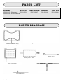
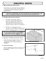
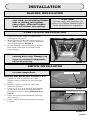
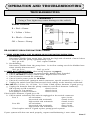
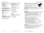
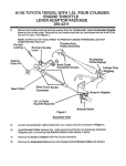
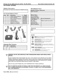
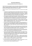
UNIVERSAL LUMBAR
INSTALLATION INSTRUCTIONS
CONTENTS
Parts List ..............................................................
Parts Diagram.......................................................
Helpful Hints.........................................................
Installation............................................................
Operation and Troubleshooting Guide...................
Warranty Information............................................
2
2
3
4
6
8
Form #3132, Rev. F, 11-02-07
PARTS LIST
BLADDER
SWITCH
250-02038 Standard 250-02054
250-02042 Front Mount
PUMP/POUCH HARNESS
250-02047
250-02046
HDW PKG
250-02044
PARTS DIAGRAM
12in. (30.5cm)
Standard Bladder Assy
(250-1453 KIT)
10.25in. (26.0cm)
Pump/Pouch Connector
Switch Assy
Pump/Pouch Assy
Front Bladder Assy
(250-1454 KIT)
Main Harness
Fused Harness
PAGE 2
HELPFUL HINTS
1. BEFORE STARTING INSTALLATION:
Familiarize yourself with the installation
instructions and lumbar seating system
components (switch, harness, pouch
and bladder)
NOTE: FOR
EASE OF INSTALLATION, YOU MAY REMOVE THE SEAT FROM THE VEHICLE.
IF
THIS STEP IS PERFORMED, YOU MUST ENSURE THAT ON RE-INSTALLATION, THE
SEAT IS TORQUED ACCORDING TO THE MANUFACTURER’S SPECIFICATION.
2. AIR BAG AND ANTI-THEFT RADIO:
a. If vehicle is equipped with an
ANTI-THEFT RADIO, the radio code
must be written down prior to
disconnecting battery cable. The
code must be re-entered when the
negative battery cable is re-installed.
b. If vehicle is equipped with an
AIR BAG, it is advisable to disconnect
negative battery cable for 3 minutes.
!WARNING!
DO
AIRBAG
TUBING, AND
AIRBAG CIRCUITS)
NOT TAP OR SOLDER TO ANY
CIRCUITS(YELLOW TAPE,
CONNECTORS
WILL INDICATE
3. REMOVAL OF NEGATIVE BATTERY CABLE:
Disconnect the negative battery cable
before installing lumbar system
components as a safety precaution.
FIGURE A
FIGURE A
4. ACCESSORY POWER:
When installing the special terminal into
fuse panel of vehicle. Use as shown in
FIGURE B.
FIGURE B
PAGE 3
INSTALLATION
BLADDER INSTALLATION
NOTE:
BLADDER
PERFORMANCE DEPENDS GREATLY ON
POSITIONING AND HOW WELL THE BLADDER IS
SECURED IN PLACE.
STEP 1:
To detach the seat cover apply one of the following
steps:
A. J-Clips: Insert panel puller into channel (in the
seam on bottom edge of seat back) and pull the
other side of the seam over the channel to
release.
B. Zipper: Unzip as necessary.
C. Hog-Ring: Requires Hog-ring pliers and
replacement rings. Cut existing rings to remove.
D. Removable Pocket: Held in with push-pins or
screws. Usually removed from bottom edge of
seat back.
E. Rigid back: Remove screws from bottom edge of
seat back.
STEP 2:
To expose the seat cushion apply the following
steps:
A. Turn the seat cover inside-out as you roll it up.
B. Working from the rear, detach the front of the
seat cover from the frame. It will be held in
place by Velcro, Springs, Hog-rings or Tie-bar
(visible from bottom edge)
STEP 3:
A. If the seat has spring support it will use a rear
mounted bladder. There are three sizes:
1) Standard 250-02038 12in. (30.5cm) or more
2) Extended 250-02039 12in. (30.5cm) or more
3) Small 250-02041 10.5in. (26.5cm) or more
B. If the seat is molded plastic or foam without
any support it will require a front mounted
bladder (250-02042)
12in(30.5cm)
standard/extended
bladder
FIGURE 1
10in(26.5cm)
small bladder
FIGURE 2
front bladder
STEP 4:
To mount the bladder:
A. STANDARD/EXTENDED/SMALL BLADDER
(FIGURES 1 & 2) Insert bladder between springs
and seat back cushion (inflatable bag toward
cushion and tube down). route tube to the right
and guide tube next to seat hinge and exit
under seat. Make sure tube routes inside of the
seat hinges, not around the outside. Use tie
straps to secure bladder back to seat springs.
B. FRONT BLADDER: (FIGURE 3)
Use double sided tape and/or cable ties to
secure bladder back to cushion.
PAGE 4
FIGURE 3
INSTALLATION
BLADDER INSTALLATION
NOTE: Tube should be routed away from
seat track. Avoid kinking bladder
tube or rubbing tube against
sharp edges. Inflatable bladder
must not contact seat springs.
!CAUTION!
Do not apply any external air
sources to inflate bladder other
than manufacturer supplied.
PUMP/POUCH INSTALLATION
1. Connect bladder tube to rubber hose
coming out of pouch.
2. Mount pouch under seat and secure to
seat using cable ties or ratchet fasteners
where appropriate. FIGURE 4
3. Secure bladder tube and pouch rubber
hose with cable ties to prevent them
from moving.
NOTE: Do not add holes to pouch, use
existing holes only. Damage can
occur to enclosed components
and void warranty.
cable ties
FIGURE 4
SWITCH INSTALLATION
NOTE: Console or seat plastic cuts best
at room temperature.
seat panel switch
SWITCH INSTALLATION: FIGURES 5 & 6
1. Choose a switch location on a flat
surface on the console or the seat side
panel.
2. Remove center console or side seat
panel as needed.
3. Cut a 1/2” x 1-3/8” hole in the console
or the seat side panel using ROSTRA
tool (250-1428) or using TEMPLATE A ON
PAGE 6.
4. Place the bezel from hardware package
onto switch.
5. Insert switch through opening and snap
in place.
FIGURE 5
center console switch
FIGURE 6
PAGE 5
INSTALLATION
Switch Template A
(Actual size)
WIRING HARNESS INSTALLATION
SWITCH INSTALLATION: FIGURES 5 & 6
1. Remove side scuff plate and kick panel.
2. Starting at the scuff plate, route three pin pump connector end of harness
under carpet to exit through opening under the seat, and connect to pump.
For seat mount switch connect three pin switch connector end of harness to
switch. (If no carpet opening, create as required.)
3. Route three pin switch connector end of harness under carpet to console
and connect to switch (For console mount switch).
4. Wrap foam adhesive around switch connection to prevent rattles.
5. Route red (power) and black (ground) wires along scuff plate, under carpet,
toward fuse panel.
6. FOR POWER, cut the red wire on the extension harness to desired length and
solder OR use attached butt splice to fused harness, also solder the other
end of fused harness to a positive Accessory fuse (fused 5 Amp or greater)
OR Insert the red wire with special terminal from fused harness assembly to
a +12V Accessory fuse (fused 5 Amp or greater).
FOR GROUND, cut the black wire on the lumbar harness to desired length,
install ring terminal supplied and attach to a ground point.
OPERATION AND TROUBLESHOOTING
OPERATION PROCEDURES
OPERATION:
The switch is used to operate the system. If your lumbar system was installed correctly, it
should perform as indicated below.
INFLATE/DEFLATE:
To inflate the bladder, depress the high side of switch. The pump motor will continue
pumping air until bladder maximum is reached, then overflow will vent out through the
pump system.
To deflate bladder, depress the low side of the switch, and with your body weight pressure, the bladder will vent out the air as long as you hold the switch.
PAGE 6
OPERATION AND TROUBLESHOOTING
TROUBLESHOOTING
! WARNING !
Using a Test Light may cause damage to the vehicle.
WIRING DIAGRAM
R = Red = Power
Y = Yellow = Valve
B = Black = Ground
GR = Green = Pump
RE-CONNECT NEGATIVE BATTERY CABLE.
1. PUMP OPERATIONAL BUT BLADDER IS NOT INFLATING/DEFLATING:
a. Not inflating:
Disconnect bladder from pump hose. Depress the high side of switch. Check if there
is air flow from the pump, approximately 2 psi.
No?- go to 2f.
Yes?- replace bladder
b. Not deflating:
Disconnect bladder from the pump hose. Is air flow coming out of the bladder hose
when initially disconnected?
No?- go to 1a.
Yes?- go to 2f.
2. PUMP NOT OPERATIONAL: (See wiring diagram on page 6)
a. Check 5 Amp lumbar Fuse to power system. Replace fuse if needed.
b. Check 12 Volts Accessory vehicle Fuse. Replace fuse if needed.
c. Check harness Ground for continuity.
d. Check Vehicle power point for 12 Volts.
e. Check all connections. (pump & switch connector, special terminal, fuse splice...)
f. Unplug the switch from the harness and check voltage at the harness connection:
* For 12V GR= 0 Volts , R= 12 Volts , Y= 0 Volts. If bad replace harness, If good go to g.
g. Unplug the harness from the pump connector and check harness continuity:
GR at pump to GR at switch=
closed circuit
Y at pump to Y at switch=
closed circuit
B at pump to vehicle Ground=
closed circuit,
If bad replace harness, if good go to 2h.
h. Check switch continuity with switch unplugged at the switch connector:
R to Y
no activation=
open circuit
low switch side activated=
closed circuit
high switch side activated=
closed circuit
R to GR
no activation=
open circuit
low switch side activated=
open circuit
high switch side activated=
closed circuit
If bad replace switch. If good replace pump/pouch system.
If your system still does not work properly, repeat troubleshooting 1 more time.
PAGE 7
WARNING: The information in this manual has been carefully compiled through actual
!
vehicle testing and manufacturers service manual research and to the best of our
ability is accurate . However, we do not warrant the accuracy of this information
against changes in vehicle design, the use or misuse of this information or typographical errors. It is the responsibility of the installer to verify the proper wire attachments
prior to and after the installation of the Lumbar System to assure proper operation.
We do not accept any responsibility for damage to the vehicle or injury to its occupants caused by the use of this information. Improper installation and/or connection
to the incorrect wires could cause Lumbar System or vehicle malfunction, component
damage and/or personal injury for you and/or your passengers.
36 MONTH/36,000 MILE LIMITED WARRANTY
Rostra Precision Controls, Inc. (the Company) warrants to the original retail purchaser of this product
that should this product or any part thereof, under normal use and conditions, be proven to have
defective material or workmanship within 36 months or 36,000 miles of the original purchase, such
defect(s) will be repaired or replaced (at the Company’s option) without charge for the parts. This
warranty does not apply to batteries or normal wear and tear associated with the Product.
To obtain repair or replacement with the terms of this Warranty, the product is to be delivered with
proof of warranty coverage (e.g. dated bill of sale), specification of defect(s), transportation prepaid, to
the installing dealer and/or retailer.
This Warranty does not cover costs incurred for the removal or reinstallation of the product, and/or
related components, and/or damage to the vehicle’s electrical system or components.
This Warranty does not apply to any product or part thereof which in the opinion of the Company has
been damaged through alteration, improper installation, misuse, neglect, accident, or customer abuse.
This Warranty is in lieu of all other express warranties or liabilities. ANY IMPLIED WARRANTIES,
INCLUDING ANY IMPLIED WARRANTY OF MERCHANTABILITY, SHALL BE LIMITED TO THE
DURATION OF THIS WRITTEN WARRANTY. ANY ACTION FOR BREACH OF ANY WARRANTY HEREUNDER INCLUDING ANY IMPLIED WARRANTY OF MERCHANTABILITY MUST BE BROUGHT WITHIN
A PERIOD OF 18 MONTHS FROM DATE OF ORIGINAL PURCHASE. IN NO CASE SHALL THE
COMPANY BE LIABLE FOR ANY CONSEQUENTIAL OR INCIDENTAL DAMAGES FOR BREACH OF
THIS OR ANY OTHER WARRANTY, EXPRESS OR IMPLIED, WHATSOEVER. No person or
representative is authorized to assume for the Company any liability other than expressed herein in
connection with the sale of this product.
THE EXTENT OF THE COMPANY’S LIABILITY UNDER THIS WARRANTY IS LIMITED TO THE REPAIR
OR REPLACEMENT PROVIDED ABOVE AND, IN NO EVENT, SHALL THE COMPANY’S LIABILITY
EXCEED THE PURCHASE PRICE PAID BY THE PURCHASER FOR THE PRODUCT.
Some states do not allow limitations on how long an implied warranty lasts or the exclusion or
limitation of incidental or consequential damage so the above limitations or exclusions may not apply
to you. This Warranty gives you specific legal rights and you may also have other rights which vary
from state to state.
ROSTRA PRECISION CONTROLS INC.
2519 Dana Drive * Laurinburg, NC 28352 * (910) 276-4853
OWNER’S WARRANTY RECORD
(To be completed by selling dealer and retained by customer)
Customer’s Name ________________________________________________________________
Address ________________________________________________________________________
Dealer Name ____________________________________________________________________
Dealer Address ___________________________________________________________________
City ____________________________________ State ____________ Zip ___________________
Date Purchased ________ Date Installed __________ Make & Year of Car __________________
Mileage at Installation ____________________________________________________________