1
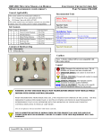
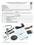
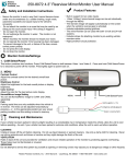
UNIVERSAL SEAT HEATER
INSTALLATION INSTRUCTIONS
CONTENTS
Parts List ..............................................................
Parts Diagram.......................................................
Helpful Hints.........................................................
Installation............................................................
Operation and Troubleshooting Guide...................
Warranty Information............................................
2
2
3
4
6
8
Form #4708, Rev. C, 01-13-09
PARTS LIST
KIT#
CONTROLLER
250-1550
250-2225
Item
F
ELEMENT
250-2226
A
SWITCH
250-2239
E
HARNESS
250-2228
B,C,D
SACK PTS
250-2229
G
SWITCH EXTENSION HARNESS (May be ordered separately)
250-2240
H
PARTS DIAGRAM
Heater Element ‘A’
Controller Harness ‘B’
Control Module ‘F’
Sack Parts ‘G’
Scotch Lock
Cable Ties
Ring
Terminal
Extension Harness ‘C’
Fused Harness ‘D’
PAGE 2
Switch Assy ‘E’
Switch Extension Harness ‘H’
HELPFUL HINTS
1. BEFORE STARTING INSTALLATION:
a. Automotive electrical experience is
beneficial for this installation
b. Familiarize yourself with the
installation instructions and seat
heater system components, prior to
installing the system.
2. AIR BAG AND ANTI-THEFT RADIO:
a. If vehicle is equipped with an
ANTI-THEFT RADIO, the radio code
must be written down prior to
disconnecting battery cable. The
code must be re-entered when the
negative battery cable is re-installed.
b. If vehicle is equipped with an
AIR BAG, it is advisable to disconnect
negative battery cable for 3 minutes
before beginning installation.
3. REMOVAL OF NEGATIVE BATTERY CABLE:
Disconnect the negative battery cable
before installing seat heater system
components as a safety precaution.
FIGURE 1
4. ACCESSORY POWER:
When installing the special terminal into
fuse panel of vehicle, use as shown in
FIGURE 2.
FIGURE 1
!WARNING!
DO NOT TAP OR SOLDER TO ANY
AIRBAG CIRCUITS (YELLOW TAPE,
TUBING, AND CONNECTORS WILL
INDICATE AIRBAG CIRCUITS)
5. NOTES:
a. Refer to vehicle owner’s manual for
any wiring identification.
b. Seats manufactured using the “foam
in place” method of trim cover
attachment will not be applicable at
this time.
c. Verify that all seat motions are still
possible without any interference
from harnesses or switch
installation.
d. Remove the seat from the vehicle
and place on a clean work bench.
FIGURE 2
PAGE 3
INSTALLATION
SEAT HEATER ELEMENT
STEP 1:
Remove seat back cover and cushion cover to expose seat foam.
A. Seat cover attachment types:
* J-Clips: Insert panel puller into channel (in the seam on bottom edge of
seat back) and pull the other side of the seam over the channel to
release.
* Zipper: Unzip as necessary.
* Hog-Ring: Requires Hog-ring pliers and replacement rings. (Cable ties
can be substituted) Cut existing rings to remove.
* Removable Pocket: Held in with push-pins or screws. Usually removed
from bottom edge of seat back.
* Rigid back: Remove screws from bottom edge of seat back.
B. Seat back cover:
a. Turn the cover inside-out as you roll it up.
b. Working from the rear, remove the front of the seat cover from the frame.
It will be held in place by Velcro, Springs, Hog-rings or Tie-bar (visible
from bottom edge).
C. Seat cushion cover:
Working from the bottom of the seat, unsnap the J-clips and/or the
Hog-rings to expose the bottom seat cushion.
!WARNING!
It is important for the proper function of this system and to insure a
malfunction does not occur that special attention is given to the installation of
the seat heater element relative to the seat foam. If the element is folded, or
creased over onto itself it may cause a premature failure of the system. In
addition, it is important that the installer does not pierce or short the element
with metal devices such as Hog-rings, or etc.
!WARNING!
Do NOT Cut or Trim the element.
STEP 2:
Mount Element ‘A’ On Seat Cushion:
FIGURE 3
A. Both elements provided in kit
are identical.
B. Ensure element width will fit in
the desired location.
C. Remove the protective layer
from the double sided tape on
the heater element and center
side to side on the seat cushion
keeping the heater element
away from any plastic or metal
objects. The harness from the
element should be routed toward the
PAGE 4 cable ties.
upper
element
element
harness
toward
back of
the seat
lower
element
FIGURE 3
back of the seat and secured with
INSTALLATION
STEP 3:
Mount Element ‘A’ On Back Rest Cushion: FIGURE 3
ON PAGE
4
A. Repeat Steps 2B and 2C.
B. Remove the protective layer from the double sided tape on the heater element and
center side to side on the seat cushion keeping the heater element away from any
plastic or metal objects. The harness from the element should be routed toward the
bottom of the seat and secured with cable ties.
CONTROLLER MODULE
1. Connect the 10 pin connector on the controller harness ‘B’ to the controller module
‘F’ connector.
2. The default setting for the system is Back and Both Mode. Cut away the external
wire loop to get High and Low Mode operation.
3. Secure the controller module ‘F’ and harness ’B’ to the underside of the seat
cushion frame using cable ties.
SWITCH INSTALLATION
BOTH ELEMENTS
OR HIGH SETTING
NOTE: Seat plastic cuts best at room temperature.
1. Choose a switch location on a flat surface where
switch wires won’t interfere with seat movement.
2. Mark the switch location, cut an opening using a
punch tool or drill bit (13/16 in. or 21mm).
3. Insert switch Assy ‘E’ through opening and snap in
place. FIGURE 4
FIGURE 4
BACKREST ONLY
OR LOW SETTING
WIRING HARNESS INSTALLATION
1. Remove side scuff plate and kick panel of the vehicle.
2. Starting under the seat, route three wire extension harness ‘C’ through carpet
opening under the seat toward scuff plate, run the harness along the scuff plate
toward the fuse panel. (If no carpet opening, create as required)
3. FOR POWER, cut the red wire on the extension harness ‘C’ to desired length and
solder OR use attached butt splice to fused harness ‘D’, also solder the other end of
fused harness ‘D’ to a positive Accessory fuse (fused 10Amp or greater) OR Insert
the red wire with special terminal from fused harness ‘D’ assembly to a positive
Accessory fuse (fused 10 Amp or greater)
FOR GROUND, cut the black wire on the extension harness ‘C’ to desired length,
install ring terminal supplied and attach to a suitable ground source.
FOR IGNITION, cut the green wire of the extension harness ‘C’ to desired length and
solder to ignition power. (Improper installation could drain your battery if you
solder to a constant battery source.)
4. Verify that all wires and connectors are secured to seat frame with cable ties.
PAGE 5
INSTALLATION
FINAL ASSEMBLY
1. Connect the wires from the seat heating element (lower & back rest) to the controller
harness ‘B’ under the seat. Check that the element in the seat back is connected to
the harness ‘B’ lead that is labeled BACK.
2. Re-install seat back cover and cushion cover. Relocate seat into vehicle. (Do NOT
install mounting bolts)
3. Connect the switch Assy ‘E’ to the controller harness ‘B’ under the seat.
4. Connect the extension harness ‘C’ to the controller harness ‘B’ under the seat.
NOTE: Verify that all connections are secured and the seat movement will not
interfere with harness.
5. Install seat mounting bolts making certain to torque mounting bolts to
manufacturers recommended specifications.
6. Re-connect the negative battery cable per owner’s manual, and test the function of
the seat heater.
7. Re-check all systems and Accessories where components were removed or relocated
during the installation process.
8. Re-install scuff plate and kick panel.
OPERATION AND TROUBLESHOOTING
OPERATION PROCEDURES
The seat heater system provides lumbar heat alone or both lumbar and cushion heat in
Back and Both Mode. It provides heat on both surfaces at two temperatures for the
High/Low setting.
OPERATION: The switch is used to operate the system. It has a BOTH/HI setting
and a BACK/LOW setting. If your seat heater system was installed correctly, it should
perform as indicated below. To turn the heater system on, turn the vehicle ignition to ‘on’
position.
BACK/BOTH ACTIVATION: The external wire loop must be intact for this mode.
Placing the switch in the ‘LO’ position, LED turns RED, warms the backrest alone. Placing
the switch in the ‘HI’ position, LED turns GREEN, warms both the backrest and seat
cushion. The controller module will regulate the seat temperatures until the switch setting is changed or until the vehicle ignition is turned off. Placing the switch in the center
position turns the system off.
HI/LOW ACTIVATION: The external wire loop must be cut away for this mode. Placing
the switch in the ‘LO’ position will warm up both element surfaces. The controller module
will regulate the temperature until the switch setting is changed or the vehicle ignition is
turned off. Placing the switch in the ‘HI’ position will warm up the element surfaces to a
warmer temperature level. The controller module will regulate the temperature until the
switch setting is changed or the vehicle ignition is turned off. Placing the switch in the
mid-position turns the system off.
PAGE 6
OPERATION AND TROUBLESHOOTING
TROUBLESHOOTING
! WARNING !
Using a Test Light may cause damage to the vehicle. It is
recommended to use a Volt/Ohm meter for all electrical testing.
A: NO HEAT
POSSIBLE CAUSES
STEP 1
No ACC.
STEP 2
STEP 3
STEP 4
STEP 5
STEP 6
SOLUTION
*Check all connections, vehicle ACC fuse, in line
10 amp fuse, fix or replace if needed.
No IGN. power
*Check all connections, vehicle ignition fuse, fix or
replace as needed.
No Ground
*Check ground connections for continuity.
Switch
*Check connection, if okay disconnect switch from
harness. Using an Ohm meter, measure the following
functions for continuity:
SWITCH BACK/LO
SWITCH BOTH/HI
SWITCH OFF
(position O)
(position I)
(position II)
Black to Blue
open circuit
closed circuit
open circuit
Black to Pink
open circuit
open circuit
closed circuit
(If not okay, replace switch, if okay go to Step 5)
Element
*Check all connections, if okay disconnect element from
harness, using an ohm meter, measure the resistance
across sensor, yellow wires (at Room Temp.) = 19 to 21k
ohms, if not replace element, if okay check continuity
across element, white wires = 5 ohms or less, if not
okay, replace element, if okay go to Step 6.
Harness
*Disconnect controller Harness ‘B’ and check
continuity per wiring diagram on top of this page. If
not okay, replace Harness ‘B’. If okay, disconnect the
extension harness ‘C’ from main harness and check for
continuity: Ground black wire, Ignition green wire, and
Accessory red wire. If not okay, replace Harness ‘C’, if
okay, replace controller module ‘F’.
B: LOW HEAT
The system is operational, the amount of heat felt by the occupant could vary if the plus
pad on the seat cover is 1/4 in. or more in thickness.
PAGE 7
WARNING: The information in this manual has been carefully compiled through actual
!
vehicle testing and manufacturers service manual research and to the best of our
ability is accurate . However, we do not warrant the accuracy of this information
against changes in vehicle design, the use or misuse of this information or typographical errors. It is the responsibility of the installer to verify the proper wire attachments
prior to and after the installation of the Seat Heater System to assure proper operation. We do not accept any responsibility for damage to the vehicle or injury to its
occupants caused by the use of this information. Improper installation and/or connection to the incorrect wires could cause Seat Heater System or vehicle malfunction,
component damage and/or personal injury for you and/or your passengers.
36 MONTH/36,000 MILE LIMITED WARRANTY
Rostra Precision Controls, Inc. (the Company) warrants to the original retail purchaser of this product
that should this product or any part thereof, under normal use and conditions, be proven to have
defective material or workmanship within 36 months or 36,000 miles of the original purchase, such
defect(s) will be repaired or replaced (at the Company’s option) without charge for the parts. This
warranty does not apply to batteries or normal wear and tear associated with the Product.
To obtain repair or replacement with the terms of this Warranty, the product is to be delivered with
proof of warranty coverage (e.g. dated bill of sale), specification of defect(s), transportation prepaid, to
the installing dealer and/or retailer.
This Warranty does not cover costs incurred for the removal or reinstallation of the product, and/or
related components, and/or damage to the vehicle’s electrical system or components.
This Warranty does not apply to any product or part thereof which in the opinion of the Company has
been damaged through alteration, improper installation, misuse, neglect, accident, or customer abuse.
This Warranty is in lieu of all other express warranties or liabilities. ANY IMPLIED WARRANTIES,
INCLUDING ANY IMPLIED WARRANTY OF MERCHANTABILITY, SHALL BE LIMITED TO THE
DURATION OF THIS WRITTEN WARRANTY. ANY ACTION FOR BREACH OF ANY WARRANTY HEREUNDER INCLUDING ANY IMPLIED WARRANTY OF MERCHANTABILITY MUST BE BROUGHT WITHIN
A PERIOD OF 42 MONTHS FROM DATE OF ORIGINAL PURCHASE. IN NO CASE SHALL THE
COMPANY BE LIABLE FOR ANY CONSEQUENTIAL OR INCIDENTAL DAMAGES FOR BREACH OF
THIS OR ANY OTHER WARRANTY, EXPRESS OR IMPLIED, WHATSOEVER. No person or
representative is authorized to assume for the Company any liability other than expressed herein in
connection with the sale of this product.
THE EXTENT OF THE COMPANY’S LIABILITY UNDER THIS WARRANTY IS LIMITED TO THE REPAIR
OR REPLACEMENT PROVIDED ABOVE AND, IN NO EVENT, SHALL THE COMPANY’S LIABILITY
EXCEED THE PURCHASE PRICE PAID BY THE PURCHASER FOR THE PRODUCT.
Some states do not allow limitations on how long an implied warranty lasts or the exclusion or
limitation of incidental or consequential damage so the above limitations or exclusions may not apply
to you. This Warranty gives you specific legal rights and you may also have other rights which vary
from state to state.
ROSTRA PRECISION CONTROLS INC.
2519 Dana Drive * Laurinburg, NC 28352 * (910) 276-4853
OWNER’S WARRANTY RECORD
(To be completed by selling dealer and retained by customer)
Customer’s Name ________________________________________________________________
Address ________________________________________________________________________
Dealer Name ____________________________________________________________________
Dealer Address ___________________________________________________________________
City ____________________________________ State ____________ Zip ___________________
Date Purchased ________ Date Installed __________ Make & Year of Car __________________
Mileage at Installation ____________________________________________________________