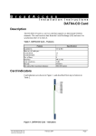
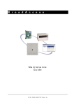
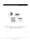
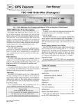
1
B r o a d A c c e s s
Installation Instructions
LI-4WE&M Card
Description
The LI-4WE&M card is a service which supports E&M signaling and
transmission for either 2W or 4W subscribers.
Fixed time slot allocation, required for normal functioning of the 4WE&M line
ports assigned to the LI-4WE&M card, is automatically configured for each
4WE&M line port when the card is installed in the cage. Permanent allocation is
automatically assigned by the system. It can be disabled using management
software. E&M type and gain are also set through the management software.
Refer to the BroadAccess Configuration Guide supplied in the Service Manual
and in the ClearAccess+ User Guide for more information about permanent
allocation and LI-4WE&M line properties.
Table 1. LI-4WE&M Card – Features
Feature
Installed in
Max no. of cards per:
CAGE40-M
CAGE40-MIN
No. of lines
Interface
Specification
CU & RU
15
4
Up to 5, depending on E&M type (see Table 2)
2W, 4W, 6W or 8W, depending on E&M type (see
Table 2)
Table 2. E&M Types
Type
Type I
Type II
Type III
Type IV
Type V
Note:
Signaling
No. of Lines Supported
2-wire E&M signaling
4-wire E&M signaling
2-wire E&M signaling
4-wire E&M signaling
2-wire E&M signaling
4-wire E&M signaling
2-wire E&M signaling
4-wire E&M signaling
2-wire E&M signaling
4-wire E&M signaling
5 lines
5 lines
4 lines
4 lines
4 lines
4 lines
4 lines
4 lines
5 lines
5 lines
Different E&M types can be used at CU and RU sides of the same BroadAccess
system.
P/N 760-000166 Rev B
000166b.doc 15/02/2004 17:49
February 2004
Page 1
Card Indicators
Card Indicators
Card indicators are shown in Figure 1, and described from top to bottom in
Table 3.
LI-4W
E&M
LD1
LD2
Figure 1. LI-4WE&M Card – Indicators
Table 3. LI-4WE&M Card – Indicator Descriptions
Indicator
LD1
LD2
Note:
Color
Red LED
Status
ON
OFF
Green LED ON
OFF
Indication
Card failure
Card functioning normally
Card functioning normally (fixed allocation)
Card failure
A self-test or forced-test will cause the LEDs on the card to flash until the test
procedure is completed. If a fault occurs, the red LED will remain ON.
Configuration
There are no user configurable strapping options on this card.
Page 2
February 2004
P/N 760-000166 Rev B
BroadAccess LI-4WE&M Card - Installation Instructions
Installation
Note:
System may remain powered while inserting card.
Caution: Modules can be damaged by electrostatic discharge (ESD). Before handling any
modules connect your wrist to an equipment ground using an approved anti-static
wrist strap. Ensure that all uninstalled modules are stored in anti-static packing
material. When working with modules, always place the module on an electrically
grounded approved anti-static mat.
Caution: Using excessive force when seating cards and modules into the backplane may
result in severe physical damage to the backplane pins or module connectors, and
if power is applied, may result in serious electrical damage to both the modules or
the backplane.
1. Place the grounded ESD wristband on your wrist.
2. Carefully remove card from package.
3. Slide the card into the cage as follows:
CAGE40-M - slots marked “1” to “15”.
CAGE40-MIN - slots marked “1” to “4”.
Caution: Seat the card into the backplane by sliding it through the card guide while holding
the ejector ears open. Fully seat the card by pressing the ejector ears in until they
lock into place. Do not force the cards into the backplane. If excessive resistance
is felt, remove the card and check for proper alignment in card guides or
obstructions.
4. If not already connected, connect cables to the cage as explained in “Cables”,
below.
Caution: If installing a new system, do not set the power cards main switch to ON until
system installation is complete, as described in the installation guide for your
specific cage.
Note:
For BroadAccess in Automatic Connection Mode:
Verify that a compatible card (see “Compatibility” in the Card Installation
Overview) is installed in the corresponding slot of the cage at the other end of the
link.
For BroadAccess in Manual Connection Mode:
Verify that a compatible card (see “Compatibility” in the Card Installation
Overview) is installed in a suitable slot of the cage at the other end of the link,
then use the management software provided with your system to perform line
provisioning accordingly. For further details, see the BroadAccess Configuration
Guide supplied in the Service Manual and in the ClearAccess+ User Guide.
P/N 760-000166 Rev B
February 2004
Page 3
Cables
5. After both the CU and RU are installed, powered up, and links are connected,
verify that indicator status is as described in “Card Indicators” above.
Otherwise, refer to “Alarms and Troubleshooting” in the BroadAccess
Maintenance Guide supplied in the Service Manual and in the ClearAccess+
User Guide.
6. Set parameters such as E&M type and Gain settings via the management
software. Refer to the management software online help or the BroadAccess
Configuration Guide for more information.
Cables
Caution: Use caution when routing wires and cables. Avoid severe bending and routing
over sharp edges. Use grommet material when possible to avoid wear to cable
insulation.
4WE&M lines are connected to the BroadAccess systems using one of the
following methods:
• connection to BroadAccess distribution blocks
• connection to BroadAccess open cables
The distribution block and open cable connections for the various E&M types are
detailed on the following pages as follows:
Table Name
Table 4. Type I, Type V and PLR Type I 4WE&M Connections
Table 5. Type I, Type V and PLR Type I 2WE&M Connections
Table 6. Type II, Type III, Type IV and PLR Type II 4WE&M
Note:
Page #
8
8
11
The connection of wires differs between E&M types, so it is important to refer to
the connection figure for the appropriate type when connecting cables.
Connection Procedure
Caution: Ensure correct polarity when connecting E&M pairs. Failure to observe this note
will cause system malfunction.
1. Identify M and E wires on the 4WE&M lines from the local exchange MDF
and from subscriber equipment.
2. Connect the 4WE&M lines (Tx, Rx, E, M, SB and SG wires) to the distribution
blocks or to the open cables, as described in the connection figures and tables
below.
Figure 2 demonstrates how to use the information given in the connection tables
(Table 4 to Table 7).
Page 4
February 2004
P/N 760-000166 Rev B
BroadAccess LI-4WE&M Card - Installation Instructions
Note:
Figure 2 shows a general explanation for using the following tables. There are
slight format changes between the tables and the figure, depending on connection
type.
Note:
Refer to the appropriate MDF Installation Instructions supplied with your system
for the location of terminals on the distribution blocks.
Type of Connection
(Distribution Block or
Open Cable)
Subscriber Line No. for the
Corresponding Card
Connector No. on
Cage Motherboard
Card Slot in Cage
SLOT CONN
#
#
1
P11
TYPE
SUBSCRIBER LINE #
1
2
3
Tx
Rx
Tx
Rx
Tx
Rx
1
2
3
4
5
6
Open
Cable
WH,
BL
WH,
OR
WH,
GR
WH,
BR
M
E
M
E
M
E
Terminal #
16 L
16 R
15 L
15 R
14 L
14 R
Open
Cable
WH BL/GR
(Tip) (Ring)
Terminal #
P7
WH BL/OR
(Tip) (Ring)
Wire Colors for
Open Cable
WH,
WH,
GY BL/WH
WH BL/WH
(Tip) (Ring)
Function
Terminal No. on 16-Line
Distribution Block
Figure 2. Explanation for Using Connection Tables
Figure 3 shows a general view of the E&M lines signaling with and without the
BroadAccess system.
When M lead (subscriber A) is connected to GND, it is being detected by the M
wire in the CU side. As a result on the RU side (subscriber B) M lead is also
connected to GND.
S u b s c rib e r A
S u b s c rib e r B
S IG N A L IN G
TRUNK
B ro a d A c c e s s
S u b s c rib e r A
S IG N A L IN G
CU
TRUNK
RU
S u b s c rib e r B
S IG N A L IN G
TRUNK
Figure 3. E&M Signaling
P/N 760-000166 Rev B
February 2004
Page 5
Cables
Figure 4 and Figure 5 show a general view of 2W and 4W configurations,
respectively.
Subscriber B
Signal
Tx/Rx
CU
RU
Tx/Output
Tx/Output
Rx/Input
Subscriber A
Signal
Tx/Rx
Rx/Input
Figure 4. 2W Connection Diagram
Subscriber B
Signal
Tx
CU
RU
Subscriber A
Signal
Tx/Output
Tx/Output
Tx
Rx
Rx
Rx/Input
Rx/Input
Figure 5. 4W Connection Diagram
Type I, Type V and PLR Type I E&M Signaling Connections
The following figures detail signaling connection diagrams for E&M type I, type
V and PLR type I.
Note:
Figure 6, Figure 7 and Figure 8 detail the E&M signaling connection for both 2W
and 4W configurations. See Figure 4 and Figure 5 for 2W and 4W configuration
diagrams.
-48V
-48V
Detector
M
M
E
E
Trunk
Trunk to Signaling
onhk = Open M
ofhk = Short M to GND
Detector
Signaling
Signaling to Trunk
onhk = Open E
ofhk = Short E to GND
E&M Type V signaling
Figure 6. Type V Connection Diagram
Page 6
February 2004
P/N 760-000166 Rev B
BroadAccess LI-4WE&M Card - Installation Instructions
-48V
M
M
E
E
Detector
-48V
Detector
Trunk
Signaling
Trunk to Signaling
onhk = Short M to GND
ofhk = Short M to -48V
Signaling to Trunk
onhk = Open E
ofhk = Short E to GND
Figure 7. Type I Connection Diagram
-48V
Detector
M
M
-48V
E
E
Detector
Trunk
Signaling
Trunk to Signaling
onhk = Open E
ofhk = Short E to GND
Signaling to Trunk
onhk = Short M to GND
ofhk = Short M to -48V
E&M PLR Type I signaling
Figure 8. PLR Type I Connection Diagram
P/N 760-000166 Rev B
February 2004
Page 7
Cables
Table 4 describes the 4WE&M type I, type V and PLR type I connections for
CAGE40-M and CAGE40-MIN cages.
Table 4. Type I, Type V and PLR Type I 4WE&M Connections
Type
Subscriber
1
Line # Per Card
2
Tx
Channel # 1
Open
WH,
Cable
BL
Rx
2
WH,
OR
Tx Rx
3
4
WH, WH, BR
GR
Tx
5
WH,
GY
M
Channel # 16 L
Open
WH
Cable
(Tip)
E
16R
GR/BR
(Ring)
M
15L
WH
(Tip)
M
14L
WH
(Tip)
E
15R
GR/WH
(Ring)
3
4
5
Rx
6
WH,
BL/WH
Rx
Tx
8
9
WH, WH,
BL/GR BL/B
R
E
M
13R 12L
OR/BR WH,
(Ring) (Tip)
Rx
10
WH,
BL/GY
Tx
7
WH,
BL/O
R
E
M
14R
13L
OR/GY WH
(Ring) (Tip)
E
12R
OR/GR
(Ring)
WH=White, YE=Yellow, BL=Blue, OR=Orange, GR=Green, BR=Brown, GY=Gray, L=Left, R=Right
TRM = Distribution Block Terminal, CONN = Connector on System Backplane, N/A = Not Applicable
Table 5 describes the 2WE&M type I, type V and PLR type I connections for
CAGE40-M and CAGE40-MIN cages.
Table 5. Type I, Type V and PLR Type I 2WE&M Connections
Type
Subscriber
1
Tx/Rx
Channel 1
#
Open
WH, BL
Cable
M
E
Channel 16 L 16R
#
Open
WH GR/BR
Cable (Tip) (Ring)
2
Tx/Rx
3
Line #
Per Card
3
Tx/Rx
5
4
Tx/Rx
7
5
Tx/Rx
9
WH,
GR
WH,
GY
WH,
BL/OR WH,
BL/BR
M
15L
E
15R
M
14L
E
14R
M
13L
E
13R
E
12R
WH
(Tip)
GR/WH WH OR/GY WH
(Ring) (Tip) (Ring) (Tip)
M
12L
OR/BR WH,
(Ring) (Tip)
OR/GR
(Ring)
WH=White, YE=Yellow, BL=Blue, OR=Orange, GR=Green, BR=Brown, GY=Gray, L=Left, R=Right
TRM = Distribution Block Terminal, CONN = Connector on System Backplane, N/A = Not Applicable
Page 8
February 2004
P/N 760-000166 Rev B
BroadAccess LI-4WE&M Card - Installation Instructions
Type II, III and IV E&M Signaling Connections
The following figures detail signaling connection diagrams for E&M type II, type
III, type IV and PLR type II.
Note:
Figure 9, Figure 10, Figure 11 and Figure 12 detail the E&M signaling for both 2
wire and 4 wire configurations. See Figure 4 and Figure 5 for 2W and 4W
configuration diagrams.
-48V
-48V
SB
SB
M
M
SG
SG
E
E
Detector
Trunk
Detector
Signaling
Trunk to Signaling
onhk = Open M to SB
ofhk = Short M to SB
Signaling to Trunk
onhk = Open E to SG
ofhk = Short E to SG
Figure 9. Type II Connection Diagram
-48V
-48V
SB
SB
M
M
SG
SG
E
E
Detector
Trunk
Trunk to Signaling
onhk = Short M to SG
Open M to SB
ofhk = Short M to SB
Open M to SG
Detector
Signaling
Signaling to Trunk
onhk = Open E
ofhk = Short E to GND
Figure 10. Type III Connection Diagram
P/N 760-000166 Rev B
February 2004
Page 9
Cables
-48V
Detector
SB
SB
M
M
SG
SG
E
E
Trunk
-48V
Detector
Signaling
Trunk to Signaling
onhk = Open M to SB
ofhk = Short M to SB
Signaling to Trunk
onhk = Open E to SG
ofhk = Short E to SG
Figure 11. Type IV Connection Diagram
Detector
SB
SB
M
M
SG
SG
E
E
Trunk
-48V
Detector
Signaling
Trunk to Signaling
onhk = Open M to SB
ofhk = Short M to SB
Signaling to Trunk
onhk = Open E to SG
ofhk = Short E to SG
Figure 12. PLR Type II Connection Diagram
Page 10
February 2004
P/N 760-000166 Rev B
BroadAccess LI-4WE&M Card - Installation Instructions
Table 6 describes the 4WE&M type II, type III, type IV and PLR type II
connections for CAGE40-M and CAGE40-MIN cages.
Table 6. Type II, Type III, Type IV and PLR Type II 4WE&M
Type
Subscriber
1
Tx
Channel # 1
Open
WH,
Cable
BL
M
Channel # 16 L
Open
WH
(Tip)
Cable
SB
Channel # 12L
Open
WH
Cable
(Tip)
2
Line #
Per Card
3
Rx
Tx
Rx
Tx
Rx
2
3
4
5
6
WH, OR WH, GR WH, BR WH, GY WH,
BL/WH
E
M
E
M
E
16R
15L
15R
14L
14R
GR/WH WH
GR/BR WH
OR/GY
(Ring) (Tip)
(Ring) (Tip)
(Ring)
SG
SB
SG
SB
SG
12R
11l
11R
10L
10R
OR/GR WH
BL/GY
OR/WH WH
(Ring) (Tip)
(Ring) (Tip)
(Ring)
4
Tx
7
WH,
BL/OR
M
13L
WH
(Tip)
SB
9L
WH
(Tip)
Rx
8
WH,
BL/GR
E
13R
OR/BR
(Ring)
SG
9R
BL/BR
(Ring)
WH=White, YE=Yellow, BL=Blue, OR=Orange, GR=Green, BR=Brown, GY=Gray, L=Left, R=Right
TRM = Distribution Block Terminal, CONN = Connector on System Backplane, N/A = Not Applicable
Table 7 describes the 2WE&M type II, type III, type V and PLR type II
connections for CAGE40-M and CAGE40-MIN cages.
Table 7. Type II, Type III, Type IV and PLR Type II 2WE&M Connections
Type
Subscriber
1
Tx/Rx
Channel # 1
Open
WH,
Cable
M
Channel # 16 L
Open
WH
Cable
(Tip)
SB
Channel # 12L
Open
WH
Cable
(Tip)
Line #
Per Card
2
3
Tx/Rx
5
WH,
4
BL
Tx/Rx
3
WH,
GR
E
16R
GR/BR
M
15L
WH
E
M
15R
14L
GR/WH WH
E
M
14R
13L
OR/GY WH
E
13R
OR/BR
(Ring)
SG
12R
OR/GR
(Ring)
(Tip)
SB
11L
WH
(Tip)
(Ring)
SG
11R
OR/WH
(Ring)
(Ring)
SG
10R
BL/GY
(Ring)
(Ring)
SG
9L
BL/BR
(Ring)
(Tip)
SB
10L
WH
(Tip)
GY
Tx/Rx
7
WH,
(Tip)
SB
9R
WH
(Tip)
BL/OR
WH=White, YE=Yellow, BL=Blue, OR=Orange, GR=Green, BR=Brown, GY=Gray, L=Left, R=Right
TRM = Distribution Block Terminal, CONN = Connector on System Backplane, N/A = Not Applicable
P/N 760-000166 Rev B
February 2004
Page 11