1
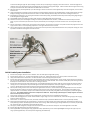
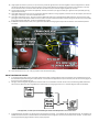
3) 4) 5) 6) Remove OEM inlet hose from engine. This can be done by removing the manifold, or by destroying OEM part. Install supplied oil line onto OEM oil line fitting. Make sure to tighten down or oil leak can occur. Some bending of OEM oil line will be necessary to clear turbo. Extra care must be taken to ensure the hard line doesn’t break. Wait to bend line once turbo is ready to drop into engine bay. Prepare for Turbo kit mock up. This is done to help align the wastegate to uppipe and downpipe. • Install 4 studs into uppipe, and install gasket to flange. • Install turbo onto uppipe and install 10mm nuts, but leave 1/2 turn loose. • Install downpipe to turbo (using gasket between connection), and leave M8 bolts 1/2 turn loose. • Install Wastegate to uppipe making sure to install valve seat between wastegate and uppipe. Leave v-‐band clamp loose enough to allow rotation of wastegate. (Use of Anti-‐Seize on inside of clamps can aid in installation) • Slide wastegate dump tube (on downpipe) up to wastegate outlet. Install and fully tighten v-‐band clamp. • Snug down bolts on downpipe, and then fully tighten bolts on uppipe. This will align wastegate to uppipe and downpipe. Fully tighten remaining wastegate flange to uppipe. • Remove (4) bolts on downpipe and slide downpipe off of wastegate dump tube and from turbo. Prepare to clock turbo for installation. • Install Oil drain fitting into oil drain flange, making sure to use anti-‐seize or Teflon paste on threads. Line up fitting to one of the holes in flange. This fitting is an NPT type fitting and seals using the taper in the threads. Thread fitting in by hand and turn an addition 2-‐2.5 turns with a wrench to seal properly. • Install oil drain fitting onto turbo making sure to install gasket between turbo and flange using supplied bolts. Make sure and place drain so outlet points away from the flange as in the picture. • Re-‐clocking (rotating the housings to line up) is required to align compressor/center housing, and turbine housing. Loosen bolts on outside turbo (6 bolts on the compressor, and 6 on the turbine). Rotate center section until brass drain fitting hits the uppipe flange. Rotate drain fitting roughly .25” away from flange. Tighten turbine-‐housing bolts to secure rotation. NOTE: If rotated too far away, oil will pool in turbo and cause oil consumption. This will still not be perfectly vertical, but do not worry. (SEE PICTURE) • Rotate compressor housing until compressor outlet is facing toward the throttle body, and tighten back down. Some rotation may be needed later in the install, but getting it close is necessary for installation. • Preinstall turbo/uppipe assembly to manifold to determine oil drain tube length. Simply use a couple OEM bolts to hold it to the manifold. Using supplied 1/2” hose, attach to brass fitting on turbo drain and install supplied clamp. Install included reducer into OEM oil drain tube, and cut 1/2” hose to length. • Install a short piece of PERRIN Pyroshield to drain hose making sure to cover all the way the the brass fitting. Install drain hose to reducer fitting, and install clamp. It is critical to not cause a kink in the line as it will cause pooling of oil in turbo.