1
G3/G4 Facsimile
Error Code List
REVISION 2
SEPT. 2001
COPYRIGHT © 2001 CANON INC.
HY8-23A0-020
CANON G3/G4 FACSIMILE ERROR CODE LIST SEPT. 2001
Application
This manual has been issued by Canon Inc. for qualified persons to learn technical theory, installation,
maintenance, and repair of facsimiles. This manual covers all localities where the facsimiles are sold. For
this reason, there may be information in this manual that does not apply to your locality.
Corrections
This manual may include technical inaccuracies or typographical errors due to improvements or changes in
products. When changes occur in applicable products or in the content of this manual, Canon will issue
technical information as the need arises. In the event of major changes in the contents of this manual over a
long or short period. Canon will issue a new editions of this manual.
The following paragraph does not apply to any countries where such provisions are inconsistent with local
law.
Trademarks
The product names and company names described in this manual are the registered trademarks of the individual companies.
Copyright
This manual is copyrighted with all rights reserved. Under the copyright laws, this manual may not be
copied, reproduced or translated into another language, in whole or in part, without the written consent of
Canon Inc.
Copyright © 2001 by Canon Inc.
CANON INC.
Consumer Imaging Products Quality Assurance Dept. 1
5-1 Hakusan 7-Chome, Toride-city, Ibaraki 302-8501, Japan
DTP System
This manual was produced on a Windows98®, personal computer, final pages were printed on AGFA
SelectSet Avantra 25.
All graphics were produced with Adobe Illustrator 9.0J®.
All documents and all page layouts were created with Adobe PageMaker 6.5®.
Introduction
INTRODUCTION
About This Manual
This manual is a compilation of error codes and repair instructions for Canon facsimile machines prepared in the form of tables.
The repairs instructions are not limited to specific models and, therefore, tend to be general in
nature. For descriptions unique to a specific model, refer also to its Service Manual.
I
Introduction
CONTENTS
INTRODUCTION .............................................................................................................. I
OUTLINE OF ERROR CODES ...................................................................................... III
HOW TO USE THIS MANUAL ........................................................................................ IV
DEFINITIONS OF THE TERMS AND EXPRESSIONS .................................................. V
Chapter 1 User Error Codes ........................................................................................ 1-1
Chapter 2 Service Error Codes .................................................................................... 2-1
Appendix
1. ISOLATING A TROUBLE .......................................................................................... A-1
1.1 3-Point Communication ...................................................................................... A-1
2. CONTROL PROCEDURE AND SIGNALS USED FOR G3 ..................................... A-2
2.1 G3 Control Procedure ........................................................................................ A-2
2.2 ECM Control Procedure ..................................................................................... A-3
2.3 V.8/V.34 Control Procedure ................................................................................ A-4
2.4 Signals Transmitted by the Transmitter .............................................................. A-5
2.5 Signals Transmitted by the Receiver .................................................................. A-6
2.6 Common Signals Transmitted by Transmitter/Receiver ...................................... A-8
2.7 Signals Transmitted by the Transmitter (unique to ECM communication) .......... A-8
2.8 Signals Transmitted by the Receiver (unique to ECM communication) ............. A-9
2.9 Signals Transmitted by the Transmitter (unique to the V.8 procedure) ............. A-10
2.10 Signals Transmitted by the Receiver (unique to the V.8 procedure) .............. A-10
2.11 Signals Transmitted by the Transmitter (unique to the V.34 procedure) ......... A-10
2.12 Signals Transmitted by the Receiver (unique to the V.34 procedure) ............ A-11
2.13 Signals Transmitted by the Transmitter/Receiver
(unique to the V.34 procedure) ..................................................................... A-11
2.14 Expected Signals ........................................................................................... A-12
2.15 FIF .................................................................................................................. A-14
2.16 List of Maker Codes ....................................................................................... A-23
3. HOW TO RECORD THE PROTOCOL .................................................................... A-25
4. CONTROL PROCEDURE AND SIGNALS USED FOR G4 ................................... A-26
4.1 Channel D Control Procedure .......................................................................... A-26
4.2 Channel B Control Procedure .......................................................................... A-27
4.3 Major Signals Used for Channel D Layer 2 ...................................................... A-28
4.4 Major Signals Used for Channel D Layer 3 ...................................................... A-28
4.5 Major Signals Used for Channel B Layer 2 ...................................................... A-29
4.6 Major Signals Used for Channel B Layer 3 ...................................................... A-29
4.7 Major Signals Used for Channel B Layer 4 ...................................................... A-29
4.8 Major Signals Used for Channel B Layer 5 ...................................................... A-30
4.9 Major Signals Used for Channel B Layer 6 ...................................................... A-31
5. COMPARISON OF ERROR CODES ...................................................................... A-32
II
Introduction
OUTLINE OF ERROR CODES
An error code is used to indicate a fault in a machine, and is indicated in the machine's LCD or
reports, showing the nature (symptoms) of the fault. Using the error code, the user or the service
man can readily find out how to correct the fault by simply referring to the User's Manual or this
manual.
An error code may be either of the following two types:
User Error Codes
A fault indicated as a user error code is one that can easily be corrected by the user, as by
operating the machine. It takes the form of "#+number." The User's Manual also provides lists
of user error codes with instructions to correct the faults they indicate.
Service Error Codes
If a fault calls for a service man for correction, it is indicated as a service man error code in the
form of "##+number." The Service Manual offers lists of service error codes, and those error
codes requiring work unique to the model in question are provided with specific instructions
for correction.
The signals discussed in this manual are explained in the Appendix if they relate to communication procedures; for others, see related manual such as the Facsimile Basic 2000.
NOTE
A service error code expressed in the form of "##+number" will not appear on
the LCD, Error Tx Report, or Activity Report while the machine remains in
factory default state. To check a service error code, shift bit 0 of service soft
switch #1 SSSW SW01 to '1'.
III
Introduction
HOW TO USE THIS MANUAL
Guide to Error Code Tables
1
2
3
4
##000 [TX/RX] Communication cannot be made [xx model]
Cause
7
Remedy
A
Malfunctioned because of an echo.
Provide echo remedy 1*7
Using a manual call, press the Start
button after hearing the 1st DIS from
the other party.
A-1
A-2
B
The other party disconnected the line
while in reception.
The procedure signal has a fault.
Transmit once again.
B-1
C
5
6
1. Error code: If the model uses a 4-digit code (e.g., 0001 through 0999), ignore the first '0'.
(For example, '##0751' must be read '##751'.)
2. [TX]: An error occurring at time of transmission.
[RX]: An error occurring at time of reception.
[TX/RX]: An error occurring at time of transmission or reception.
3. Gives a description of the error code.
4. [xx model]: indicates an error code unique to the model in question.
5. Provides a description of the possible cause of the error code in question.
6. Shows action to take to correct the error.
• For Cause A, Remedies may be A-1 and A-2.
• For Causes B and C, the common Remedy B-1 may be used.
• If multiple remedies are provided as in the case of Cause A, go through them in the given
order (i.e., if A-1 fails to correct the fault, perform A-2).
7. If a description is underlined and marked with an asterisk with a number, you will find
explanations on the next page.
IV
Introduction
DEFINITIONS OF THE TERMS AND EXPRESSIONS
The terms and expressions used in this manual are defined as follows:
1. Transmission Level (ATT): No.07 of Service Soft Switch #2 MENU
Increase the transmission level:
Increase the setting so that it is closer to 0 dBm. (At 0 dBm, the LCD indicates '0'.) Some
models, however, do not allow the setting to be increased to 0 dBm.
Decrease the transmission level:
Decrease the setting so that it is closer to -15 dBm. (At -15 dBm, the LCD indicates '15'.)
2. NL Equalizer: No.05 of Service Soft Switch #2 MENU
Adjust the NL equalizer:
Select 'ON'.
3. Transmission Page Timer: SW12 of Service Soft Switch #1 SSSW
Increase the page timer setting:
To set both transmission and reception to the same time-out length, set SW12 as follows:
8 min: bit 7, bit 1, bit 0 = 0, 0, 0
16 min: bit 7, bit 1, bit 0 = 0, 0, 1
32 min: bit 7, bit 1, bit 0 = 0, 1, 0
64 min: bit 7, bit 1, bit 0 = 0, 1, 1
If you want to set transmission and reception to different time-out lengths, or use different
time-out lengths according to different image modes, you will have to set all bits (from 7
through 0) accordingly. For details, see the G3 Facsimile Service Data Handbook.
4. T0 Timer: No.10 of Service Soft Switch #3 NUMERIC param.
Increase the T0 timer setting:
Increase the setting of No.10.
The T0 timer is used to set the period of time in which a line connection is recognized for
transmission, i.e., in which the machine waits for a significant signal from the other party after
dialing. The line will be disconnected if no significant signal is received during the period.
5. T1 Timer: No.11 of Service Soft Switch #3 NUMERIC param.
Increase the T1 timer setting:
Increase the setting of No.11.
The T1 timer is used to set the period of time in which a line connection is recognized for
reception, i.e., in which the machine waits for a significant signal from the other party after
transmission of DIS. The line will be disconnected if no significant signal is received during
the period.
V
Introduction
6. RTN Signal Transmission Condition: No. 02, 03, and 04 of Service
Soft Switch #3 NUMERIC param.
Loosen the RTN signal transmission condition:
Increase the settings of No.02, 03, and 04.
No.02 is used to set the ratio of the number of error lines to the total number of lines per page
(1% to 99%).
No.03 is used to set the burst error (number of successive error lines identified as an errors); (2
to 99 lines).
No.04 is used to set the number of errors falling short of a burst error (1 to 99 times).
7. Echo Remedy
An echo remedy is provided on the part of either the transmitting machine or the receiving
machine.
Echo Remedy 1 (by the transmitting machine; for long distance):
By the User:
Set the long distance mode as part of registering for auto-dialing (one-touch dialing, coded
speed dialing):
• If set to 'long distance 1', the machine will ignore the 1st DIS transmitted by the other party.
• If set to 'long distance 2', the machine will transmit a 1850-Hz tonal signal in response to DIS
from the other party.
• If set to 'long distance 3', the machine will transmit a 1650-Hz tonal signal in response to DIS
from the other party.
By the Service Man:
Changing SW03 bit 6, bit 5, and bit 4 of service soft switch #1 SSSW will affect all settings,
i.e., all transmissions will be long distance transmissions:
long distance 1:
bit 6, bit 5, bit 4 = 0, 0, 1
long distance 2:
bit 6, bit 5, bit 4 = 0, 1, 0
long distance 3:
bit 6, bit 5, bit 4 = 1, 1, 0
Echo Remedy 2 (by the receiving machine; adds a 1080-Hz total signal before
transmission of CED):
Set SW03 bit 7 of service soft switch #1 SSSW to '1' so that a 1080-Hz total signal is transmitted before transmission of CED.
Echo Remedy 3 (by the receiving machine; changes the period in which the low speed
signal is ignored after transmission of CFR):
Set SW04 bit 4 of service soft switch #1 SSSW to '1' so that the period in which the low speed
signal is ignored after transmission of CFR is changed from 700 to 1500 msec.
8. Echo Protect Tone: SW03 bit 1 of Service Soft Switch #1 SSSW
Add an echo protect tone to the V.29 modem signal for transmission:
When SW03 bit 1 is set to '1', an echo protect tone will be added to high-speed transmission
V.29 (at 9600 or 7200 bps) for transmission.
VI
Introduction
9. Number of Final Flag Sequences: SW04 bit 2 of Service Soft Switch
#1 SSSW
Increase the number of final flag sequences:
When SW04 bit 2 is set to '1', the number of final flag sequences will be increased from 1 to 2
for a procedure signal (transmitted at 300 bps).
10. Closed Network Function: SW07 bit 7, bit 6, SW08 of Service Soft
Switch #1 SSSW
Set the closed network transmission function to 'Yes':
Set SW07 bit 7 to '1'.
Set the closed network reception function to 'Yes':
Set SW07 bit 6 to '1'.
Match the closed network ID:
Match the settings of SW08 bit 0 through bit 7.
On some models, you may make the closed network settings using the user soft switch and
register a closed network ID as part of user data.
11. Subaddress
A subaddress is used to indicate the location of a memory box in the other party (e.g., confidential mailbox, polling box), and it consists of 20 or fewer characters (numerals, *, #, space). As
log as the other party complies with the International Standards of ITU-T, the machine can
communicate with it by means of subaddresses.
At times, an ID number (referred to as a "password") is used to restrict access to a location
indicated by a subaddress.
With some models, polling based on subaddresses is called "selective polling," and a subaddress
used at time of polling is called a "selective polling address."
12. Password
A password used by a Canon facsimile machine may be any of the following:
Polling Password:
This is an ID number used for polling between Canon machines, and is also called a "polling
ID." Some models use 8 binary characters (00000000 through 11111111), while some machines use 3 decimal characters (000 through 255).
Password for Subaddress Communications:
This is an ID number used for a subaddress communication and, as in the case of a subaddress,
it consists of 20 or fewer characters (numerals, *, #, space).
Communication Password:
This is an ID number used for a password communication. Some models use 4 decimal characters (0000 through 9999), while some use 3 decimal characters (000 through 255).
VII
Introduction
NOTE
Password Used When Making Settings:
A password may also be used for confidential mailboxes, memory lock Rx,
call restriction, and other functions. Such a password consists of 4 decimal
characters (0000 through 9999), and it is important to remember that these
passwords are used inside the machine and are not intended for communication procedures.
13. Modes of Transmission
Normal Transmission:
A normal transmission is one that does not specify the confidential, broadcast, or subaddress
function.
Memory Transmission:
In memory transmission, all documents data is read into memory before dialing for transmission. While memory transmission is taking place, the next document may be read for subsequent transmission (memory transmission reservation).
Direct Transmission:
In direct transmission, the other party is dialed to make a connection, and then documents are
read one by one for transmission. Since the next document is not read until the one being
processed has been transmitted, memory transmission reservation cannot be selected.
Quick Memory Transmission:
In this mode, the other party is dialed while an document is being read into memory. When all
documents have been read into memory, memory transmission reservation may be selected as
in the case of memory transmission.
Rapid Transmission:
In this mode, reading of documents does not start until other party has been dialed and a
connection has been made. It is usually found in a model with a high reading speed. When all
documents have been read into memory, memory transmission reservation may be selected as
in the case of memory transmission.
14. Signals
Tonal Signal:
A tonal signal consists of sinusoidal waves of a specific frequency, and may be thought of as a
sound carrying a meaning. CNG, CED, and ANSam are tonal signals.
Binary Signal:
A binary signal is used to indicate the meaning of a procedure. It is either '1' or '0', modulated
according to frequency, and is used as G3 procedure signals.
Procedure Signal:
It is a generic term for a tonal signal and a binary signal.
Preamble:
It is a signal attached to the beginning of a binary signal, and is used to synchronize modem
signals for a procedure signal.
Image Signal:
Of procedure signals, it is used for actual transmission of image data.
VIII
Introduction
Significant Signal:
It is a signal whose significance can be understood by a facsimile machine that receives it, and
it is free of a transmission error.
Message:
Signals in an ISDN communication are at times called a message.
15. Timer
T0 Timer:
It indicates the period of time in which a line connection is recognized during transmission;
specifically, the machine waits for a significant signal from the other party after dialing.
T1 Timer:
It indicates the period of time in which a line connection is recognized during reception; specifically, the machine waits for a significant signal from the together party after transmission
of DIS.
T5 Timer:
It is the period of time in which RR/RNR is transmitted during an ECM communication.
T.62 T1 Timer:
It is the period of time in which the absence of signals is monitored as part of a channel B
communication procedure.
T.62 T2 Timer:
It is the period of time in which the machine waits for a response as part of a channel B
communication procedure.
T.62 T3 Timer:
It is a CSA timer used as part of a channel B communication procedure.
IX
Introduction
This page intentionally left blank.
X
Chapter 1
User
Error Codes
Chapter1: User Error Codes
#001
[ TX ] Document has jammed
Cause
Remedy
• The document is trapped in the feeder.
• Remove the document, and try again.
• The document is not of a standard size or
thickness.
• Using a copying machine, make an A4/LTR
copy of the document to transmit.
• If too small or thin, use a carrier sheet
(document cover) to transmit.
• An internal mechanism is faulty.
• Correct it by referring to the Service
Manual of the model in question.
#002
[ TX ] Document is shorter than indicated
Cause
Remedy
• The document is shorter than the length
indicated in [minimum] of [sheet dimensions] given as specifications in the Service Manual of the model in question.
• Use a carrier sheet (document over) to
transmit.
• Using a copying machine, make an A4/LTR
copy of the document to transmit.
1-1
Chapter1: User Error Codes
#003
[ TX/RX ] Document is too long, or page time-over
Cause
Remedy
• The length of a single page is too long.
• Using a copying machine, make copies of
the document, and transmit the copies separately.
• Use a copying machine.
• The data of a single page is too large, exceeding the time allowed for transmission.
• Decrease the reading resolution when
transmitting.
• If the document is too long and the data is
too large, make copies using a copying machine, and transmit the copies separately.
• If halftone transmission is used, the document is of a default size, and the data is too
large, increase the setting of the page
timer*3.
• The data of a single page is too large, exceeding the time allowed for reception.
• Ask the operator of the other party to decrease the reading resolution and transmit.
• Ask the operator of the other party to divide the document and transmit.
• Increase the setting of the page timer*3.
• Ask the operator of the other party to find
out the cause.
• An internal mechanism is faulty.
• Correct it by referring to the Service
Manual of the model in question.
1-2
Chapter1: User Error Codes
#004
[ TX ] Voice communication (i.e., telephone in
advance) cannot be made
Cause
Remedy
• The other party is not any of the following
types: FAX 30/31, 220, 230, 320E, 330,
510, 520, 610, 620, 710, 730.
• Contact the other party, and see to it that
the machine is not any of the models indicated. (The function is intended exclusively
for the FAX 30/31).
#
[
]
Cause
Remedy
1-3
Chapter1: User Error Codes
#005
[ TX/RX ] Initial identification (T0/T1) time-over
Cause
Remedy
• The tone/pulse setting is wrong.
• Make the correct tone/pulse setting.
• The time it takes to connect to the other
party's line is too long.
• When registering an auto-dial number, put
a relatively long pause after the telephone
number to delay the T0 timer start mechanism.
• To prevent a time-over condition, increase
the T0 timer setting*4. (for transmission)
• To prevent a time-over condition, increase
the T1 timer setting*5. (for reception).
• The other party does not respond.
• Contact the operator of the other party, and
find out the cause.
• The other party's communication mode
(G2, G3, etc.) does not match.
• The communication mode depends on each
specific model, and no remedy can be offered.
• The 2nd dial tone does not arrive for transmission to F-NET (Facsimile communication network services). [Japanese model]
• Check to find out that a subscription has
been signed for F-NET; then, inform the
telephone company of that the line is out
of order.
• During transmission, the other party malfunctioned because of an echo.
• Provide echo remedy 1*7.
• Using a manual call, press the Start button
after hearing the 1st DIS from the other party.
• To prevent response to the 1st DIS from
the other party, put a relatively long pause
to the telephone number when registering
an auto-dial number.
• Ask the operator of the other party to provide echo remedy 2*7.
• Ask the operator of the other party to decrease the transmission level*1.
• During reception, the machine malfunctioned because of an echo.
• Provide echo remedy 2*7.
• Transmission to MF1 (Minifax 1) was initiated without starting MF1 mode. [Japanese model]
• Start MF1 mode, and transmit once again.
1-4
Chapter1: User Error Codes
#006
[ TX ] Transmission cannot be made
[ RX ] Phase synchronization fails in OLD-FM
Cause
Remedy
• The Transmit button was pressed without
an document.
• Place an document before pressing the button. (exclusively for 401, 601)
• The line condition is poor, and the phase
signal cannot be received correctly.
• Ask the operator of the other party to increase the transmission level*1 so that the
phase signal may be received correctly.
• Adjust the NL equalizer*2 so that the phase
signal may be received correctly.
#007
[ TX/RX ] Talk reservation fails
[ RX ] Phase synchronization fails in G1 reception
Cause
Remedy
• The other party made a talk reservation,
but the operator of the other party does not
respond to a telephone call.
• Ask the operator of the other party to respond to the telephone call at the end of
the communication.
• The line condition is poor, and the phase
signal cannot be received correctly.
• Ask the operator of the other party to increase the transmission level*1 so that the
phase signal may be received correctly.
• Adjust the NL equalizer*2 so that the phase
signal may be received correctly.
1-5
Chapter1: User Error Codes
#008
[ TX ] Password does not match for polling
transmission
Cause
Remedy
• During Canon mode polling, the password
of the machine and that of the other party
do not match.
• If the other machine is a Canon machine,
contact the operator and try to match the
passwords.
• If the other party is a non-Canon machine,
see the password to either '11111111' or
'255'.
• Record the protocol on a DAT or MD, and
have it analyzed by the local Canon office
and/or Technical Center.
• During polling that uses a subaddress, the
password of the machine and that of the
other machine do not match.
• Match the password of the machine and
that of the other party.
#009
[ RX ] Recording paper has jammed or the
recording paper has run out
Cause
Remedy
• The recording paper is trapped.
• Remove the trapped recording paper.
• The recording paper has run out.
• Set new recording paper.
• The recording paper cassette is not set correctly.
• Set the recording paper cassette.
• An internal mechanism is faulty.
• Correct it by referring to the Service
Manual of the model in question.
1-6
Chapter1: User Error Codes
#010
[ TX/RX ] Communications control memory overflow
Cause
Remedy
• There is no recording paper so that the contents of the communications control
memory cannot be printed, ultimately causing a shortage of memory.
• Set recording paper.
#011
[ RX ] Polling reception error
Cause
Remedy
• There is no document in the other party.
• Ask the operator of the other party to set
the document correctly.
• Transmission was attempted, and polling
reception was started because the document
was not set correctly.
• Set the document correctly to transmit.
1-7
Chapter1: User Error Codes
#012
[ TX ] The other party has run out of recording
paper
Cause
Remedy
• The other party has run out of recording
paper.
• Ask the operator of the other party to set
recording paper.
#013
[ TX ] Document size error in MF1 (Minifax 1)
mode
[Japanese model]
Cause
Remedy
• An attempt was made to transmit a B4-wide
document in MF1 mode.
• Using a copying machine, make a copy of
the document in A4 or smaller, and transmit the copy.
1-8
Chapter1: User Error Codes
#014
[ TX ] Document size setting error [German model]
Cause
Remedy
• An attempt was made to transmit a nonA4 document without setting conditions.
• Set conditions for the document size, and
then transmit.
#015
[ TX ] Fine mode transmission error in G2
[German model]
Cause
Remedy
• An attempt was made to use G2 transmission after selecting fine mode.
• Use standard mode for G2 transmission.
1-9
Chapter1: User Error Codes
#018
[ TX ] Auto dialing transmission error
Cause
Remedy
• The tone/pulse setting is wrong.
• Make the correct tone/pulse setting.
• The connection time for the line is too long.
• When registering an auto-dial number, put
a relatively long pause at the end of the
telephone number to delay the start of the
T0 timer.
• Increase the T0 timer setting*4 to prevent a
time-over condition.
• The line of the other party was engaged.
• Start a call once again.
• The other party is not connected to the line,
or is not turned on so that the transmission
did not arrive.
• Ask the operator of the other party to find
out the cause.
• The other party is not a facsimile machine.
• Check the number of the other party, and
start a call once again.
• The other party ran out of recording paper
so that the line was disconnected during
the pre-procedure.
• Ask the operator of the other machine to
set recording paper.
• The 2nd dial tone does not arrive for transmission to F-NET (Facsimile communication network services). [Japanese model]
• Check to make sure that a subscription has
been signed for F-NET, and inform the telephone company that the line is out of order.
• The machine was disconnected from the
line using an unidentified reason code.
• The other party did not respond.
• The other party is out of order.
• The other party is out of use for some reason.
• The exchange is congested.
• There is no line/channel that is available at
present.
• The requested line/channel cannot be used
on the side of the other party.
• Calls crashed.
• Communication is not possible at present
by reason of terminal management.
• Wait for a while, and start a call once again.
• Check to make sure that the other party is
tuned on.
• Ask the operator of the other party to find
out the cause.
1-10
Chapter1: User Error Codes
#019
[ TX ] Memory transmission fails
Cause
Remedy
• In memory transmission (delayed transmission/re-dial transmission), the memory fails
to store image data.
• Store image data in the memory once gain,
and try memory transmission. Or, try direct transmission.
#020
[ TX ] Recording paper size does not match
Cause
Remedy
• In memory transmission or memory copying, the image size is B4 while the recording paper is A4.
• Set B4 recording paper.
1-11
Chapter1: User Error Codes
#021
[ RX ] The other party has rejected the machine
during polling reception
Cause
Remedy
• During Canon mode polling, the password
of the machine and that of the other party
do not match.
• Match the passwords.
• When starting a call, a subaddress, or a
subaddress and a password, was not specified.
• Specify a subaddress, or a subaddress and
a password, when starting a call.
#022
[ TX ] Call fails
Cause
Remedy
• The data for an auto-dial number used
when selecting a party was deleted.
• Register the telephone number of the other
party as an auto-dial number, and transmit
once again.
1-12
Chapter1: User Error Codes
#023
[ TX ] Memory transmission fails
Cause
Remedy
• Memory transmission was attempted in
MF1 (Minifax 1).
• MF1 is not compatible with memory transmission. Use direct transmission.
#024
[ TX ] Delayed transmission fails
Cause
Remedy
• For combination of delayed transmission
with direct transmission, no document is
set at the specified time.
• Once the specified time passes, there is no
remedy.
1-13
Chapter1: User Error Codes
#025
[ TX/RX ] Auto-dial setting is wrong
Cause
Remedy
• The settings require registration of a
subaddress for auto-dialing; however, a call
was attempted without registering a
subaddress.
• If auto-dialing is of a type requiring registration of a subaddress, register a subaddress.
• Minifax mode was selected for auto-dialing, and an attempt was made for polling
reception.
• Minifax mode was combined with a confidential or relay setting for auto-dialing, and
an attempt was made for transmission.
• A confidential setting and a relay setting
were combined for auto-dialing, and an
attempt was made for transmission.
• Make correct auto-dial settings.
#027
[ RX ] LBP (printer) is OFF
[exclusively for L910]
Cause
Remedy
• The LBP is OFF.
• Turn on the LBP.
1-14
Chapter1: User Error Codes
#028
[ RX ] LBP (printer) does not have a cartridge
[exclusively for L910]
Cause
Remedy
• The LBP does not have a toner cartridge.
• Set a toner cartridge in the LBP.
#029
[ RX ] LBP (printer) has a recording paper jam
[exclusively for L910]
Cause
Remedy
• The LBP has a recording paper jam.
• Remove the recording paper jam from the
LBP.
1-15
Chapter1: User Error Codes
#030
[ RX ] LBP (printer) has run out of toner
[exclusively for L910]
Cause
Remedy
• The toner cartridge of the LBP has run out
of toner.
• Replace the toner cartridge of the LBP.
#031
[ RX ] LBP (printer) issued a No Paper warning
[exclusively for L910]
Cause
Remedy
• The LBP has run out of recording paper.
• Supply recording paper to the LBP.
1-16
Chapter1: User Error Codes
#032
[ TX ] Power is turned off
Cause
Remedy
• A power shortage occurred while waiting
for delayed transmission.
• Make delayed transmission settings once
again.
• The power was turned off while waiting
for delayed transmission.
• Turn on the power, and make delayed transmission settings once again.
• The power supply is out of order.
• Replace the power supply unit.
#033
[ TX ] Confidential transmission cannot be used
Cause
Remedy
• The other party does not have a confidential reception function that supports Canon
mode.
• The other party does not have a function
that supports subaddress mode.
• Confidential transmission is not possible.
Try a direct mode of transmission.
1-17
Chapter1: User Error Codes
#034
[ TX ] Transmission to the confidential mailbox of
the other party cannot be made in
confidential transmission
Cause
Remedy
• The other party does not have the selected
confidential mailbox.
• Check the number of the confidential mailbox of the other party, and try again.
• The memory of the other party is full.
• Ask the operator of the other party to delete image data that is no longer needed.
#035
[ TX ] Relay control transmission cannot be used
Cause
Remedy
• The other party does not have a relay function that supports Canon mode.
• The other party does not have a function
that supports subaddress mode.
• Relay control transmission cannot be made.
Transmit directly to the final destination.
1-18
Chapter1: User Error Codes
#036
[ TX ] Relay control transmission cannot be made
Cause
Remedy
• The relay control source has not been registered as part of auto-dialing of the relay
machine.
• Ask the operator of the relay machine to
register the telephone number of the relay
control source as part of auto-dialing.
• The relay control source is wrongly registered as part of auto-dialing of the relay
machine.
• Ask the operator of the relay machine to
correct the telephone number of the relay
control source as part of auto-dialing.
• The relay switch of the relay station is OFF.
• Ask the operator of the relay station to turn
on the relay switch.
• The memory of the relay station is full.
• Ask the operator of the relay station to delete image data that is no longer needed.
#037
[ RX ] Memory has overflowed when receiving
images
Cause
Remedy
• The image memory overflowed during reception.
• Delete image data that is no longer needed,
and ask the operator of the other party to
transmit once again.
1-19
Chapter1: User Error Codes
#038
[ TX/RX ] Hard disk error
Cause
Remedy
• A fault has occurred in accessing a file on
the hard disk.
• Correct it by referring to the Service
Manual of the model in question.
#039
[ TX ] Closed network transmission fails
Cause
Remedy
• The closed network transmission function
is set to [No].
• Set the closed network transmission function to [Yes]*10.
• The closed network reception function of
the other party is set to [No].
• Ask the operator of the other party to set
the closed network reception function of
the other party to [Yes]*10.
• The closed network ID does not match that
of the other party.
• Match the closed network ID*10 of the machine and that of the other party.
1-20
Chapter1: User Error Codes
#040
[ TX ] Image memory has overflowed during
broadcasting transmission
Cause
Remedy
• The data of the document is too large for
broadcasting transmission.
• Delete image data that is no longer needed,
and start broadcasting transmission once
again.
• Divide the document, and try again.
• Decrease the resolution, and try again.
#041
[ TX ] Broadcasting transmission cannot be used
Cause
Remedy
• An attempt at broadcasting transmission
was made to an MF1 (Minifax 1) or G2
machine.
• Broadcasting transmission cannot be
made to an MF1 or G2 machine. Use normal transmission.
1-21
Chapter1: User Error Codes
#042
[ RX ] Cutter operation is faulty
Cause
Remedy
• The cutter used to cut thermal recording
paper is faulty.
• Correct it by referring to the Service
Manual of the model in question.
#043
[ RX ] Toner cartridge is missing
Cause
Remedy
• The toner cartridge is not set correctly.
• See the User's Manual of the model in question to set the toner cartridge correctly.
• The toner cartridge has run out of toner.
• Replace the toner cartridge.
• The sensor malfunctioned.
• Correct it by referring to the Service
Manual of the model in question.
1-22
Chapter1: User Error Codes
#044
[ RX ] The size of the recording paper and that of
the ink sheet cartridge do not mach
Cause
Remedy
• The size of the recording paper and that of
the ink sheet cartridge are different.
• Replace either the recoding paper or the
ink sheet cartridge so that both will be of
the same size.
• The sensor malfunctioned.
• Correct it by referring to the Service
Manual of the model in question.
#045
[ TX ] Warning has been issued for a missing
transmission
Cause
Remedy
• A mistake was made when entering the
number of documents.
• All documents have been transmitted, not
requiring action.
• The number of documents that have been
entered is lower than the number of documents placed.
• Send the missing documents.
• Double feeding of documents has occurred.
• Transmit once again.
1-23
Chapter1: User Error Codes
#046
[ RX ] Receiving restriction
Cause
Remedy
• The telephone number of the other party
has not been registered for auto-dialing.
• Register the telephone number of the other
party for auto-dialing.
• Set [receiving restriction] to [No], and ask
the operator of the other party to transmit
once again.
#047
[ RX ] Reception fails
Cause
Remedy
• The recording paper cover is opened.
• Close the recording paper cover.
• The sensor malfunctioned.
• Correct it by referring to the Service
Manual of the model in question.
1-24
Chapter1: User Error Codes
#048
[ TX ] Multi-file transmission error
Cause
Remedy
• During batch transmission, a multi-file
transmission error occurred.
• Transmit to the other party using normal
mode to find out the cause.
• Record the protocol on a DAT or MD, and
have it analyzed by the local Canon office
and/or Technical Center.
#049
[ TX ] Cipher communication cannot be used
[NTT model]
Cause
Remedy
• The Cipher key does not match that of the
other party.
• Match the Cipher key of the machine with
that of the other party.
1-25
Chapter1: User Error Codes
#050
[ TX ] Cipher transmission cannot be used
[NTT model]
Cause
Remedy
• The other party is not equipped with a cipher communication function.
• Transmit using normal mode instead of cipher mode.
• Select the fall-back function (to normal
transmission).
• Transmit to a fax machine equipped with a
cipher communication function.
#051
[ RX ] Decode error has occurred during cipher
reception
[NTT model]
Cause
Remedy
• The Cipher key does not match that of the
other party.
• Match the Cipher key of the machine with
that of the other party.
1-26
Chapter1: User Error Codes
#052
[ RX ] Recording paper footer error
Cause
Remedy
• The BJ ink has run out, causing a printer
error and thus an image memory overflow.
• Replace the BJ cartridge. If necessary, ask
the operator of the other party to transmit
once again.
#054
[ TX/RX ] Call cannot be made
Cause
Remedy
• The user ID has not been registered.
• Register the user ID.
• The user telephone number has not been
registered.
• Register the user telephone number.
1-27
[Korean model]
Chapter1: User Error Codes
#055
[ TX ] The other party does not have an MDC
(Multi Device Controller) function
[exclusively for GP55]
Cause
Remedy
• Although an attempt was made to transmit
an image from a PC, the other party is not
equipped with an MDC function.
• Transmit a printed document instead of a
coded image from a PC.
• Transmit to a party equipped with an MDC
function.
• Ask the operator of the other party to set
up the MDC function.
#056
[ RX ] Recording paper feed fault
Cause
Remedy
• The recording paper has jammed while
both pickup sensor and delivery sensor
were OFF.
• Remove the jammed recording paper from
the feeding section.
1-28
Chapter1: User Error Codes
#057
[ RX ] Recording paper feed fault
Cause
Remedy
• The recording paper has jammed while the
pickup sensor is ON and the delivery sensor is OFF.
• Remove the jammed recording paper from
the feeding section.
#058
[ RX ] Recording paper feed fault
Cause
Remedy
• The recording paper stopped and jammed
while delivery sensor was ON.
• Remove the jammed recording paper from
the feeding section.
1-29
Chapter1: User Error Codes
#059
[ TX ] Dialed number and the connected number
(CSI) do not match
Cause
Remedy
• The user telephone number is not registered correctly on the receiving side.
• Ask the operator of the receiving side to
register the user telephone number correctly.
• Use manual transmission; then, after making sure that a connection has been made,
transmit once again.
• The exchange malfunctioned, and the machine is not connected to the dialed party.
• Have the exchange checked.
#
Cause
[
]
Remedy
1-30
Chapter1: User Error Codes
#080
[ TX ] The other party is not equipped with an ITUT-compliant subaddress reception function
Cause
Remedy
• Bit 49 of DIS received from the other party
is '0'.
• Transmit to a fax machine equipped with a
subaddress function.
• If the other party is a Canon machine, make
correct settings for Canon mode (e.g., confidential transmission), and transmit.
• If the other party is a non-Canon machine,
use normal G3 transmission.
#081
[ TX ] The other party is not equipped with an ITUT-compliant password reception function
Cause
Remedy
• Bit 50 of DIS received from the other party
is '0'.
• Transmit to a fax machine equipped with a
password function.
• Use subaddress transmission that does not
use a password.
• If the other party is a Canon machine, make
correct settings for Canon mode (e.g., confidential transmission), and transmit.
• If the other party is a non-Canon machine,
use normal G3 transmission.
1-31
Chapter1: User Error Codes
#082
[ RX ] The other party is not equipped with an ITUT-compliant selective polling transmission
function
Cause
Remedy
• Bit 47 of DIS received from the other party
is '0'.
• If the other party is a non-Canon machine,
ask the operator to set normal polling transmission, and use polling reception.
• If the other party is a Canon machine, use
polling reception in Canon mode polling.
#083
[ RX ] Selective polling address or the password
does not match during ITU-T-compliant
selective polling reception
Cause
Remedy
• The selective polling address or the password of the machine does not match that
of the other machine.
• Match the selective polling address and the
password of the machine with that of the
other party.
1-32
Chapter1: User Error Codes
#084
[ RX ] The other party is not equipped with a
password function for ITU-T-compliant
selective polling reception
Cause
Remedy
• Bit 50 of DIS received from the other party
is '0'.
• Use selective polling that does not use a
password.
#085
[ TX ] The other party is not equipped with a color
reception function for ITU-T-compliant color
transmission
Cause
Remedy
• An attempt was made to use color transmission, but the other party is not equipped
with a color reception function.
• Select black-and-white transmission mode,
and transmit once again.
• If the other party is capable of color reception but is not set to declare color reception, ask the operator to change the setting.
1-33
Chapter1: User Error Codes
#099
[ TX/RX ] Stop button was pressed during a
communication
Cause
Remedy
• The Stop button was pressed during a communication.
• Try transmission once again.
• Try reception once again.
#
Cause
[
]
Remedy
1-34
Chapter1: User Error Codes
#101
[ TX ] Call cannot be made
Cause
Remedy
• The polarity of L1 and that of L2 of the
line do not match.
• Reverse L1 and L2 of the line.
#102
[ TX/RX ] Subaddress or password does not match
during an ITU-T-compliant subaddress
communication
Cause
Remedy
• The subaddress and the password of the
machine do not match that of the other
party.
• Match the subaddress and password of the
machine with those of the other party.
• An appropriate subaddress and password
are not set on the other party.
• Ask the operator of the other party to set
an appropriate subaddress and password.
• In the case of transmission, the image
memory of the party is full.
• Ask the operator of the other party to delete image data that is no longer needed,
and transmit once again.
1-35
Chapter1: User Error Codes
#103
[ RX ] User telephone number does not match
during ID reception
Cause
Remedy
• The user telephone number of the other
party has not been registered for the autodialing function of the machine.
• Register the user telephone number of the
other party for auto-dialing.
• The user telephone number has been registered wrongly for the auto-dialing function of the machine.
• Register the correct user telephone number of the other party for auto-dialing.
#104
[ TX/RX ] Password communication cannot be made
Cause
Remedy
• The other party is not equipped with a password communication function.
• Turn on the ID communication mode, and
try once again.
1-36
Chapter1: User Error Codes
#105
[ TX/RX ] User telephone number does not match
during an ID communication
Cause
Remedy
• The user telephone number has not bee registered on the other party.
• Ask the other party to register the user telephone number.
#106
[ TX/RX ] Capacity of the backup battery is not
adequate
Cause
Remedy
• When the power was OFF, the backup dry
battery of the IC used to record messages
was removed.
• The voltage dropped when the power was
OFF.
• Turn off the power, and replace the dry battery; turn on the power, and record the message once again.
1-37
Chapter1: User Error Codes
#110
[ TX/RX ] In a fax machine supporting the Internet
through a provider, a customer ID error
(invalid user ID detection) occurred during
negotiation with the server
Cause
Remedy
• The user ID registered as part of the user
data does not match the terms of the contract.
• Register the correct user ID.
• No agreement has been signed with the provider.
• Sign an agreement with the provider.
#111
[ TX/RX ] In a fax machine supporting the Internet
through a provider, a PIN code error (invalid
password detection) occurred during
negotiation with the server
Cause
Remedy
• The password registered as part of the user
data does not match the terms of the agreement.
• Register the correct password.
1-38
Chapter1: User Error Codes
#112
[ TX/RX ] In a fax machine supporting the Internet
through a provider, a shortage of prepayment was detected during negotiation
with the server
Cause
Remedy
• The pre-payment has been used up.
• Pay a charge to the provider.
#
Cause
[
]
Remedy
1-39
Chapter1: User Error Codes
#200
[ TX/RX ] F-NET (Facsimile communication network
services) service error
[Japanese model]
Cause
Remedy
• A connection to F-NET cannot be made.
• The connection to F-NET was disconnected.
• A sequential error occurred in an F-NET
service.
• Check the F-NET dialing number and the
selected service.
• Start over the communication.
#300
[ TX/RX ] Unallocated (unassigned) number
Cause
Remedy
• The called number is normal in terms of
formatting, but is an unallocated (unassigned) number and cannot reach a destination.
• Check the number, and call once again.
1-40
Chapter1: User Error Codes
#301
[ TX/RX ] Subscriber number of the other party has
changed
Cause
Remedy
• The called number is no longer in use.
• Check the number, and make a call once
again.
#
Cause
[
]
Remedy
1-41
Chapter1: User Error Codes
#995
[ TX/RX ] Memory transmission reservation clear/
memory reception image clear
Cause
Remedy
• In the case of transmission, the user canceled the memory transmission reservation.
• Transmit once again.
• In the case of reception, the user deleted
the image that had been received in
memory reception.
• Ask the operator of the other party to transmit once again.
#996
[ TX/RX ] Hard disk error
Cause
Remedy
• The hard disk is faulty.
• Correct it by referring to the Service
Manual of the model in question.
1-42
Chapter1: User Error Codes
#997
[ TX/RX ] Power was cut during a communication
Cause
Remedy
• The power went out or was turned off during a communication.
• Correct it by referring to the Service
Manual of the model in question.
• The power supply is faulty.
• Replace the power supply unit.
#998
[ RX ] Memory reception has ended
Cause
Remedy
• This code is used to indicate the result of
memory reception on the activity report.
• The result is good, and requires no remedy.
1-43
Chapter1: User Error Codes
#999
[ RX ] The image memory overflowed during
memory reception
Cause
Remedy
• During memory reception, the image data
was too large, causing the image memory
to overflow.
• Set recording paper, and ask the operator
of the other party to transmit once again.
#
Cause
[
]
Remedy
1-44
Chapter1: User Error Codes
#
[
]
Cause
#
Cause
Remedy
[
]
Remedy
1-45
Chapter1: User Error Codes
#
[
]
Cause
#
Cause
Remedy
[
]
Remedy
1-46
Chapter 2
Service
Error Codes
Chapter 2: Service Error Codes
##001
[ TX ] In telephone fax mode transmission, the
phase OK signal cannot be received
Cause
Remedy
• The line condition is poor, and the other
party cannot receive the phase signal correctly.
• Increase the transmission level*1 so that the
other party may receive the phase signal
correctly.
• Adjust the NL equalizer*2 so that the other
party may receive the phase signal correctly.
##002
[ RX ] In G2 reception, the image storage
memory goes out of order
Cause
Remedy
• The buffer memory is faulty.
• Replace the system control board.
2-1
Chapter 2: Service Error Codes
##003
[ TX ] In G2 transmission, MCF2 or PIS cannot be
received
Cause
Remedy
• The line condition is poor, and the other
party cannot receive PIS correctly.
• Increase the transmission level*1 so that the
other party may receive PIS correctly.
• Adjust the NL equalizer*2 so that the other
party may receive PIS correctly.
• The line condition is poor, and MCF2 from
the other party cannot be received correctly.
• Ask the operator of the other party to increase the transmission level*1 so that
MCF2 may be received correctly.
• Adjust the NL equalizer*2 so that MCF2
may be received correctly.
##004
[ RX ] In G2 reception, EOM or PIS cannot be
received
Cause
Remedy
• The line condition is poor, and the image
signal is not received for 1 sec or more.
(However, the 1st 5 sec immediately after
image reception operation is ignored.)
• Ask the operator of the other party to increase the transmission level*1 so that EOM
or PIS may be received correctly.
• Adjust the NL equalizer*2 so that EOM or
PIS may be received correctly.
2-2
Chapter 2: Service Error Codes
##005
[ TX ] In G2 transmission, GI2 cannot be received
Cause
Remedy
• The line condition is poor, and GI2 cannot
be received correctly.
• Ask the operator of the other party to increase the transmission level*1 so that GI2
may be received correctly.
• The other party malfunctioned because of
an echo, and does not transmit GI2.
• Ask the operator of the other party to decrease the transmission level*1 so that the
other party will not receive an echo.
##006
[ RX ] In G2 reception, phase synchronization
fails for the 2nd and subsequent pages
Cause
Remedy
• The line condition is poor, and the phase
signal from the other party cannot be received correctly.
• Ask the operator of the other party to increase the transmission level*1 so that the
phase signal may be received correctly.
• Adjust the NL equalizer*2 so that the phase
signal may be received correctly.
2-3
Chapter 2: Service Error Codes
##007
[ TX ] In G2 transmission, CFR2 cannot be
received
Cause
Remedy
• The line condition is poor, and CFR2 cannot be received correctly.
• Ask the operator of the other party to increase the transmission level*1 so that CFR2
may be received correctly.
• Adjust the NL equalizer*2 so that CFR2
may be received correctly.
• The other party has run out of recording
paper.
• Ask the operator of the other party to set
recording paper.
##008
[ RX ] In G2 reception, GC2, PIS, or phase signal
cannot be received for 35 sec and a
different signal is received
Cause
Remedy
• The line condition is poor, and the signal
immediately before the GC2, PIS, or phase
signal cannot be received.
• Ask the operator of the other party to increase the transmission level*1 so that the
signal immediately before GC2, PIS, or
phase signal may be received correctly.
• Adjust the NL equalizer*2 so that the signal immediately before GC2, PIS, or phase
signal may be received correctly.
2-4
Chapter 2: Service Error Codes
##009
[ TX/RX ] The end of the tonal signal from the other
party cannot be detected
Cause
Remedy
• The line suffered large noise.
• Contact the telephone company, and ask
for maintenance of the line.
##010
[ RX ] In G2 or MF1 mode reception, phase
synchronization cannot be made for the
1st page
Cause
Remedy
• The line condition is poor, and the phase
signal cannot be received correctly.
• Ask the operator of the other party to increase the transmission level*1 so that the
phase signal may be received correctly.
• Adjust the NL equalizer*2 so that the phase
signal may be received correctly.
2-5
Chapter 2: Service Error Codes
##011
[ RX ] In G2 reception, the image signal cannot be
received for 5 sec after transmission of
CFR2
Cause
Remedy
• The line condition is poor, and the image
signal cannot be received correctly.
• Ask the operator of the other party to increase the transmission level*1 so that the
image signal may be received correctly.
• Adjust the NL equalizer*2 so that the image signal may be received correctly.
##012
[ RX ] In G2 reception, a signal other than PIS or
GC2 is received after transmission of MCF2
or GI2
Cause
Remedy
• The procedure signal has a fault.
• Record the protocol on a DAT or MD, and
have it analyzed by the local Canon office
and/or Technical Center.
2-6
Chapter 2: Service Error Codes
##013
[ TX ] In G2 transmission, PIS is received while
transmitting an image signal
Cause
Remedy
• The other party has run out of paper.
• Ask the other party to set recording paper.
##
[
]
Cause
Remedy
2-7
Chapter 2: Service Error Codes
##050
[ RX ] The thermistor of the thermal head has
detected a fault
Cause
Remedy
• The thermal head is faulty.
• Replace the thermal head.
• The system control board is faulty.
• Correct it by referring to the Service
Manual of the model in question.
• The power supply is faulty.
• Replace the power supply unit.
##051
[ TX/RX ] The stepping motor fails to rotate normally
Cause
Remedy
• The stepping motor is faulty.
• Replace the stepping motor.
• The gear unit is faulty.
• Replace the gear unit.
• The recording paper cutter is faulty.
• Replace the recoding paper cutter.
• The system control board is faulty.
• Correct it by referring to the Service
Manual of the model in question.
2-8
Chapter 2: Service Error Codes
##052
[ TX/RX ] The contents of the backup memory are
destroyed
Cause
Remedy
• The memory was affected by noise.
• Print out all data, and execute all-clear;
then, enter the data once again.
• The backup battery is faulty.
• Replace the backup battery.
• The system control board is faulty.
• Correct it by referring to the Service
Manual of the model in question.
##053
[ TX/RX ] The thermistor of the thermal head or the
motor has detected a fault
Cause
Remedy
• Copying, transmission, or reception was
performed continuously for a long time.
• Turn off the power, and rest the machine
for a while.
• The thermal head is faulty.
• Replace the thermal head.
• The motor is faulty.
• Replace the motor.
• The thermistor is faulty.
• Replace the thermistor.
2-9
Chapter 2: Service Error Codes
##054
[ TX/RX ] Image memory backup error
Cause
Remedy
• The secondary battery for image backup
has become exhausted.
• Turn on the power, and charge the secondary battery. (However, this will not recover
the data.)
• Replace the secondary battery.
• The DRAM is faulty.
• See the Service Manual of the model in
question to replace the DRAM or the system control board inclusive of the DRAM.
##
Cause
[
]
Remedy
2-10
Chapter 2: Service Error Codes
##100
[ TX ] The number allowed for retransmission of
the procedure signal was exceeded during
transmission
Cause
Remedy
• The transmission level is too low, and the
other party cannot receive NSS, TSI, DCS,
TCF, or the training signal correctly.
• Increase the transmission level*1 so that the
other party may receive the signal correctly.
• After transmission of TCF immediately
before the image signal, the other party
malfunctioned because of an echo.
• Ask the operator of the other party to provide echo remedy 3*7.
• Using a manual call, press the Start button
after hearing the 1st DIS from the other
party.
• To prevent response to the 1st DIS from
the other party, put a relatively long pause
to the telephone number when registering
an auto-dialing number.
• After transmission of the Q signal following the image signal, the line condition
became poor so that the other party cannot
receive the image signal or the Q signal
correctly.
• Increase the transmission level*1 so that the
other party may service the image signal
or the Q signal correctly.
• Decrease the transmission start speed.
• Adjust the NL equalizer*2 so that the other
party may receive the image signal or the
Q signal correctly.
• Add an echo protect tone to the V.29 modem signal for transmission*8.
• Increase the number of final flag sequences*9 for the procedure signal so that
the other party may receive the procedure
signal correctly.
2-11
Chapter 2: Service Error Codes
##101
[ TX/RX ] The modem speed of the machine does
not match that of the other party
Cause
Remedy
• The modem speed of the machine does not
match that of the other machine.
• The modem speed is part of machine specifications, and there is no remedy.
• In the case of transmission, the speed for
fallback does not match that of the other
party.
• Increase the transmission level*1 so that the
other party may receive TCF correctly.
• Adjust the NL equalizer*2 so that the other
party may receive TCF correctly.
• Provide echo remedy 1 or 2*7.
• Using a manual call, press the Start button
after hearing the 1st DIS from the other party.
• To prevent response to the 1st DIS from
the other party, put a relatively long pause
to the telephone number when registering
an auto-dialing number.
• Ask the operator of the other party to decrease the transmission level*1 so that the
other party will not receive an echo.
##102
[ TX ] Fallback is not possible
Cause
Remedy
• The line condition is poor, and the other
party cannot receive TCF correctly.
• Increase the transmission level*1 so that the
other party may receive TCF correctly.
• Adjust the NL equalizer*2 so that the other
party may receive TCF correctly.
• An echo has caused a malfunction.
• Provide echo remedy 1*7.
• Using a manual call, press the Start button
after hearing the 1st DIS from the other
party.
• To prevent response to the 1st DIS from
the other party, put a relatively long pause
to the telephone number when registering
an auto-dialing number.
• Ask the operator of the other party to provide echo remedy 2*7.
• Ask the operator of the other party to decrease the transmission level*1 so that the
other party will not receive an echo.
2-12
Chapter 2: Service Error Codes
##103
[ RX ] EOL cannot be detected for 5 sec (15 sec if
CBT)
Cause
Remedy
• The line condition is poor, and the image
signal cannot be received correctly.
• Ask the operator of the other party to increase the transmission level*1 so that the
image signal may be received correctly.
• Ask the operator of the other party to decrease the transmission start speed.
• Adjust the NL equalizer*2 so that the image signal may be received correctly.
• The machine malfunctioned because of an
echo of CFR.
• Provide echo remedy 3*7.
• Decrease the transmission level*1 so that
an echo of transmitted CFR will not be received.
##
Cause
[
]
Remedy
2-13
Chapter 2: Service Error Codes
##104
[ TX ] RTN or PIN has been received
Cause
Remedy
• The line condition is poor so that the other
party cannot receive the image signal correctly.
• Increase the transmission level*1 so that the
other party may receive the image signal
correctly.
• Decrease the transmission start speed.
• Adjust the NL equalizer*2 so that the other
party may receive the image signal correctly.
• Add an echo protect tone to the V.29 modem signal for transmission*8.
• Ask the operator of the other party to loosen
the RTN transmission conditions*6 so that
the other party will not transmit RTN.
• The machine malfunctioned because of an
echo.
• Provide echo remedy 1*7.
• Using a manual call, press the Start button
after hearing the 1st DIS from the other
party.
• To prevent response to the 1st DIS from
the other party, put a relatively long pause
to the telephone number when registering
an auto-dialing number.
• Ask the operator of the other party to provide echo remedy 2*7.
• Ask the operator of the other party to decrease the transmission level*1 so that the
other party will not receive an echo.
2-14
Chapter 2: Service Error Codes
##105
[ RX ] Data error occurs in 40 lines or more
continuously while image signals are
received
Cause
Remedy
• The line condition is poor, and the image
signal cannot be received correctly.
• Ask the operator of the other party to increase the transmission level*1 so that the
image signal may be received correctly.
• Ask the operator of the other party to decrease the transmission start speed.
• Adjust the NL equalizer*2 so that the image signal may be received correctly.
##106
[ RX ] The procedure signal cannot be received
for 6 sec while in wait
Cause
Remedy
• The line condition is poor, and the procedure signal from the other party cannot be
received correctly.
• Ask the operator of the other party to increase the transmission level*1 so that the
procedure signal may be received correctly.
• Adjust the NL equalizer*2 so that the procedure signal may be received correctly.
• The line condition is poor, and the other
party cannot receive the signal.
• Increase the transmission level*1 so that the
other party may receive the signal correctly.
• Adjust the NL equalizer*2 so that the other
party may receive the signal correctly.
• The machine malfunctioned because of an
echo.
• Provide echo remedy 2*7.
• Decrease the transmission level*1 so that
an echo of transmitted signal will not be
received.
2-15
Chapter 2: Service Error Codes
##107
[ RX ] The transmitting machine cannot use fallback
Cause
Remedy
• The line condition is poor, and the signal
from the other party cannot be received
correctly even at 2400 bps.
• Ask the operator of the other party to increase the transmission level*1 so that the
signal may be received correctly.
• Adjust the NL equalizer*2 so that the signal may be received correctly.
• Loosen the RTN transmission conditions*6
so that RTN will not be transmitted.
• The machine malfunctioned because of an
echo.
• Provide echo remedy 2*7.
• Decrease the transmission level*1 so that
an echo of the transmitted signal will not
be received.
##108
[ TX ] Reversal of the polarity has been detected in
relation to F-NET2 (Facsimile
communication network services 2)
[Japanese model]
Cause
Remedy
• An attempt was made to send 32 or more
documents at a time.
• Divide the documents so that a single transmission will consist of 31 or fewer.
• The length of a single document is longer
than 2 A4 sheets (594 mm).
• Divide the document so that each signal is
shorter than 2 A4 sheets.
• The other party released the line while in
reception.
• Transmit once again.
• STOC has detected a fault.
• An account charge pulse occurred.
• File a problem report with NTT.
2-16
Chapter 2: Service Error Codes
##109
[ TX ] After transmitting DCS, a signal other than
DIS, DTC, FTT, CFR, and CRP was received,
exceeding the permitted number of
transmissions of the procedure signal
Cause
Remedy
• The procedure signal is faulty.
• Record the protocol on a DAT or MD, and
have it analyzed by the local Canon office
and/or Technical Center.
##110
[ TX ] PIS was detected during image
transmission
Cause
Remedy
• The other party released the line.
• Transmit once again.
2-17
Chapter 2: Service Error Codes
##111
[ TX/RX ] Memory error
Cause
Remedy
• While printing data stored in the image
memory, the effects of noise caused a data
error.
• Print out all image data and system data,
and execute all-clear; then, store the system data once again.
• Noise started wrong dialing.
• Replace the system control board.
##112
[ TX ] DIS has been received 3 times
Cause
Remedy
• The transmission level is low, and the other
party cannot receive DCS, TCF, or training signal correctly.
• Increase the transmission level*1 so that the
other party may receive the signal correctly.
• Adjust the NL equalizer*2 so that the other
party may receive the signal correctly.
• The other party malfunctioned because of
an echo.
• Using a manual call, press the Start button
after hearing the 1st DIS from the other
party.
• To prevent response to the 1st DIS from
the other party, put a relatively long pause
to the telephone number when registering
an auto-dialing number.
• Ask the operator of the other party to provide echo remedy 2*7.
• Ask the operator of the other party to decrease the transmission level*1 so that the
other party will not receive an echo.
2-18
Chapter 2: Service Error Codes
##113
[ TX ] After transmitting Q or PRI-Q, a signal other
than MCF, RTP, RTN, PIP, or PIN was received
Cause
Remedy
• The procedure signal is faulty.
• Record the protocol on a DAT or MD, and
have it analyzed by the local Canon office
and/or Technical Center.
##114
[ RX ] RTN was transmitted
Cause
Remedy
• The line condition is poor, and the image
signal from the other party cannot be received correctly.
• Ask the operator of the other party to increase the transmission level*1 so that the
image signal may be received correctly.
• Ask the operator of the other party to decrease the transmission start speed.
• Adjust the NL equalizer*2 so that the image signal may be received correctly.
• Loosen the RTN transmission conditions*6
so that RTN will not be transmitted.
• The machine malfunctioned because of an
echo of CFR.
• Provide echo remedy 3*7.
• Decrease the transmission level*1 so that
an echo of transmitted CFR will not be received.
2-19
Chapter 2: Service Error Codes
##115
[ TX ] During image transmission, the maximum
transmission time per line was exceeded
Cause
Remedy
• The document is too fine, and coding resulted in a large volume of data.
• Using a copying machine, make a copy for
transmission.
• Avoid halftone mode or the like, and use
text mode (binary mode) for transmission.
• Ask the operator of the other party to increase the EOL timer so that the maximum
transmission time per line will not be exceeded.
##116
[ TX/RX ] During a communication, suspension of
loop current was detected [Swiss model]
Cause
Remedy
• The other party released the line.
• Transmit once again.
• The exchange malfunctioned.
• The flow of loop current is not adequate.
• Contact the telephone company.
2-20
Chapter 2: Service Error Codes
##117
[ RX ] During reception, DCN was received after
transmission of DIS between pages
Cause
Remedy
• The line condition is poor, and the other
party cannot receive DIS correctly.
• Increase the transmission level*1 so that the
other party can receive the signal correctly.
• Adjust the NL equalizer*2 so that the other
party may receive the signal correctly.
• The Stop button of the other party was
pressed.
• Ask the operator of the other party to transmit once again.
##118
[ RX ] During reception, T1 time-over occurred
between pages
Cause
Remedy
• The line condition is poor, and the other
party cannot receive DIS correctly.
• Increase the transmission level*1 so that the
other party may receive the signal correctly.
• Adjust the NL equalizer*2 so that the other
party may receive the signal correctly.
• The line condition is poor, and DCS from
the other party cannot be received correctly.
• Ask the operator of the other party to increase the transmission level*1 so that the
signal may be received correctly.
• Adjust the NL equalizer*2 so that the signal may be received correctly.
2-21
Chapter 2: Service Error Codes
##120
[ TX ] Mechanism of the document feed system
is faulty
Cause
Remedy
• A fault occurred in a mechanism of the
document feed system, and the communication was suspended as a means of prevention.
• See the Service Manual of the model in
question, and see that the document feed
system is free of a fault.
##121
[ RX ] The ink sheet and the recording paper
stick to each other
Cause
Remedy
• The application energy imposed on the
thermal head is too high.
• Decrease the resistance value of the thermal head. (This, however, will make print
lighter.)
• Contac the Technical Center.
2-22
Chapter 2: Service Error Codes
##122
[ TX ] ITU-T-compliant (DIS bits 33 through 37)
transmission function is absent
Cause
Remedy
• Bit 33 of DIS received from the other party
is ON, and a declaration of the ability for
reception arrived (expressed by bits 34
through 37) however, the machine does not
have a compatible document transmission
function.
• Transmit to a facsimile machine for which
bits 33 and higher are not used.
• Transmit to a facsimile for which the ability for reception is not defined by bits 33
through 37.
##
Cause
[
]
Remedy
2-23
Chapter 2: Service Error Codes
##200
[ RX ] During image reception, a carrier is not
detected for 5 sec
Cause
Remedy
• The line condition is poor, and the image
signal cannot be received.
• Ask the operator of the other party to increase the transmission level*1 so that the
image signal may be received correctly.
• Ask the operator of the other party to decrease the transmission start speed.
• The training signal cannot be received because of an echo of CFR, causing a timeover condition.
• Provide echo remedy 3*7.
• Decrease the transmission level*1 so that
an echo of transmitted CFR will not be received.
##201
[ TX/RX ] DCN was received through a non-normal
procedure
Cause
Remedy
• The other party is not ready for reception
(e.g., out of recording paper).
• Ask the operator of the other party to set
the machine for reception (as by setting recording paper).
• The user telephone number has not been
registered (if the receiving machine is a
RICOH 3000L).
• Register the user telephone number.
• During reception, a talk reservation was
made; however, a call was not answered.
• Contact the other party by telephone.
2-24
Chapter 2: Service Error Codes
Cause
Remedy
• In polling reception of Canon mode, the
password is not correct.
• If the other party is a Canon machine, contact the operator to match the passwords.
• If the other party is a non-Canon machine,
contact the operator, and ask to set the
machine so that it will execute polling
transmission without any condition.
• In polling transmission, document is not
placed.
• Place a document, and ask the operator of
the other party to make a call once again.
• The other party transmitted, but there is no
recording paper.
• Set recording paper.
• The line condition is poor, and the other
party cannot receive the procedure signal
correctly.
• Increase the transmission level*1 so that the
other party may receive the procedure signal correctly.
• Adjust the NL equalizer*2 so that the other
party may receive the procedure signal correctly.
• The machine malfunctioned because of an
echo.
• Provide echo remedies 1, 2, or 3*7.
• Decrease the transmission level*1 so that
an echo will not be received.
• The image signal or the Q signal cannot be
received, and the other party suffered an
excess number of re-transmissions of the
procedure signal.
• Ask the operator of the other party to increase the transmission level*1 so that the
signal may be received correctly.
• Adjust the NL equalizer*2 so that the signal may be received correctly.
• Ask the operator of the other party to decrease the transmission start speed.
• The line condition is poor, anad the other
party (transmitting machine) cannot use
fall-back.
• Ask the operator of the other party to increase the transmission level*1 so that the
signal may be received correctly.
• Adjust the NL equalizer*2 so that the signal may be received correctly.
• Loosen the RTN transmission conditions*6
so that RTN will not be transmitted.
2-25
Chapter 2: Service Error Codes
##202
[ TX/RX ] The end of the procedure signal from the
other party cannot be detected
Cause
Remedy
• Large noise entered the line.
• Increase the number of final flag sequences*9 for the procedure signal so that
the other party may receive the procedure
signal correctly.
• Contact the telephone company, and request maintenance of the line.
##203
[ TX/RX ] Mistake was made in operation caused by
a factor other than #003 through #008
Cause
Remedy
• At changing transmission/reception or
polling, there was no document or recording paper (only if between FAX-410Hs).
• Place a document or recording paper.
2-26
Chapter 2: Service Error Codes
##204
[ TX ] DTC was received in the absence of
transmission data.
When using CEP2 (Canon Express
Protocol 2) for direct transmission, DIS
was received after image transmission, but
there is no transmission data
Cause
Remedy
• In the case of DTC reception, the procedure signal is faulty.
• Record the protocol on a DAT or MD, and
have it analyzed by the local Canon office
and/or Technical Center.
• When DIS was received during CEP2
transmission, the state of the other party
recognized by the machine and the current
state of the machine do not match.
• Transmit once again.
• Record the protocol on a DAT or MD, and
have it analyzed by the local Canon office
and/or Technical Center.
##205
[ TX ] Error occurred in the data while images
were being stored in memory
Remedy
• The image memory is faulty.
• Replace the transmission memory or the
PCB (e.g., system control board) on which
the transmission memory is mounted.
2-27
Chapter 2: Service Error Codes
##210
[ TX ] CD (control document) communication is
not possible
Cause
Remedy
• The other party cannot use CD communication in Canon mode.
• The other party does not support CD combination in Canon mode.
• The other party cannot use the CD communications function (i.e., Canon mode
relay and confidential for G4); try a different method of communication.
##220
[ TX/RX ] System error (e.g., main program may
have gone away)
Cause
Remedy
• Noise caused the CPU to malfunction.
• A fault occurred in the software.
• A fault occurred in the hardware.
• A hard disk error occurred.
• Turn off and then on the power.
• Correct it by referring to the Service
Manual.
2-28
Chapter 2: Service Error Codes
##221
[ RX ] The crystal oscillator for Direct recording
is faulty
Cause
Remedy
• The crystal oscillator for Direct recording
is faulty.
• Replace the unit to which the crystal oscillator for Direct recording is mounted.
• Replace the system control board.
##222
[ RX ] The crystal oscillator for 90% reduction
recording is faulty
Cause
Remedy
• The crystal oscillator for 90% reduction recording is faulty.
• Replace the unit to which the crystal oscillator for 90% reduction recording is
mounted.
• Replace the system control board.
2-29
Chapter 2: Service Error Codes
##223
[ TX ] The line was disconnected during
communication
Cause
Remedy
• The Stop button was pressed during image transmission.
• Transmit once gain.
##224
[ TX/RX ] Fault occurred in the communication
procedure signal
Cause
Remedy
• The document on the transmitting party is
not correctly fed, forcing polling mode to start
(i.e., DCN was received in response to DIS).
• Check to make user that the document is
placed correctly.
• If the feeding roller is worn, replace it.
• In a memory full condition, a call arrived
when a document was set (i.e., DCN was
received in response to DIS).
• If any image received in memory reception remains in the memory, print out the
image and empty the memory. Also, avoid
leaving a document in the document tray
unless the machine is in transmission mode.
• The procedure signal is faulty.
• Record the protocol on a DAT or MD, and
have it analyzed by the local Canon office
and/or Technical Center.
• A fault occurred in a communication procedure of G4 layer 4 or lower.
• A fault occurred in the G3 communication
procedure on an ISDN line.
• Start over the communication.
• Print out a communications analysis list for
analysis.
2-30
Chapter 2: Service Error Codes
##226
[ TX/RX ] The stack pointer shifted out of the RAM
area
Cause
Remedy
• Noise caused the CPU to malfunction.
• Turn off and then on the power.
##227
[ RX ] An attempt was made to record a file not
containing an image
Cause
Remedy
• Not identified.
• It is an error code for testing memory problems in the L770 Series; and, because of
the absence of a record of occurrence, no
remedy is available.
2-31
Chapter 2: Service Error Codes
##228
[ RX ] The image management information is
faulty
Cause
Remedy
• Not identified.
• It is an error code for testing memory problems in the L770 Series; and, because of
the absence of a record of occurrence, no
remedy is available.
##229
[ RX ] The recording system became locked for 1
min
Cause
Remedy
• Not identified.
• Correct the locking, and press the Start
button to print out the image.
• Replace the ROM. (UK version of the L770
Series only)
2-32
Chapter 2: Service Error Codes
##230
[ TX/RX ] The unit used to control the display
malfunctioned
Cause
Remedy
• The operation of the IC used to control the
display did not end normally.
• Replace the unit used to control the display (e.g., display unit).
##231
[ TX/RX ] The unit used to control the buttons
malfunctioned
Cause
Remedy
• The operation of the IC used to control the
buttons did not end normally.
• Replace the unit used to control the buttons (e.g. control panel unit).
2-33
Chapter 2: Service Error Codes
##232
[ TX ] The unit used to control the encoder is
faulty
Cause
Remedy
• The operation of the IC used to control the
encoder did not end normally.
• Replace the unit used to control the encoder
(e.g., system control board).
##233
[ TX ] The unit used to control the CCD is faulty
Cause
Remedy
• The operation of the IC used to control the
CCD did not end normally.
• Replace the unit used to control the CCD.
2-34
Chapter 2: Service Error Codes
##234
[ TX ] The unit used to control reading
malfunctioned
Cause
Remedy
• The operation of the IC used to control
reading did not end normally.
• Replace the unit used to control reading.
##235
[ TX/RX ] The unit used to control the G2 modem
malfunctioned
Cause
Remedy
• The operation of the IC used to control the
G2 modem did not end normally.
• Replace the unit used to control the G2 modem.
2-35
Chapter 2: Service Error Codes
##236
[ TX/RX ] The unit used to control the G3 modem
malfunctioned
Cause
Remedy
• The operation of the IC used to control the
G3 modem did not end normally.
• Replace the unit used to control the G3 modem.
##237
[ RX ] The IC used to control the decoder
malfunctioned
Cause
Remedy
• The operation of the IC used to control the
decoder did not end normally.
• Replace the unit used to control the decoder
(e.g., system control board).
2-36
Chapter 2: Service Error Codes
##238
[ RX ] The unit used to control recording
malfunctioned
Cause
Remedy
• The operation of the IC used to control recording did not end normally.
• Replace the unit used to control recoding
(e.g., system control board).
##239
[ TX/RX ] The unit used for tonal control
malfunctioned
Cause
Remedy
• The operation of the IC used for tonal control did not end normally.
• Replace the unit used for tonal control.
2-37
Chapter 2: Service Error Codes
##244
[ TX/RX ] The unit used to control OPT2
malfunctioned
Cause
Remedy
• The operation of the IC used to control
OPT2 did not end normally.
• Replace the unit used to control OPT2.
##260
[ TX/RX ] System error occurred between modem
and system control board
Cause
Remedy
• An internal unit is faulty (when RS is set
to '0', CS fails to go '0').
• Replace the PCB that includes the modem.
• Replace the system control board.
2-38
Chapter 2: Service Error Codes
##261
[ TX/RX ] System error occurred between the
modem and system control board
Cause
Remedy
• An internal unit is faulty (when RS is set
to '1', CS fails to go '1').
• Replace the PCB that includes the modem.
• Replace the system control board.
##262
[ TX ] In MF1 (Minifax1) transmission, the output
of the CFR detection filter fails to go OFF
[Japanese model]
Cause
Remedy
• An internal unit is faulty.
• Replace the communication control board.
2-39
Chapter 2: Service Error Codes
##263
[ TX/RX ] After detection of a preamble, no response
is received for 20 sec
Cause
Remedy
• The line has noise of a continuous nature.
• Ask the operator of the other party to increase the transmission level*1 so that the
signal may be received correctly.
• The preamble of the other party is too long.
• Ask the operator of the other party to make
the preamble 1 sec long (if it can be
changed).
• An internal unit is faulty.
• Replace the system control board.
• Replace the PCB that includes the modem.
• Replace the communication control board.
##264
[ RX ] The image signal cannot be received
correctly within 10 sec after the machine
becomes ready for image reception
Cause
Remedy
• The line condition is poor, and the image
signal cannot be received correctly.
• Ask the operator of the other party to increase the transmission level*1 so that the
image signal may be received correctly.
• Ask the operator of the other party to decrease the transmission start speed.
• Adjust the NL equalizer*2 so that the image signal may be received correctly.
• The machine malfunctioned because of an
echo of CFR.
• Provide echo remedy 3*7.
• Decrease the transmission level*1 so that
an echo of transmitted CFR will not be received.
2-40
Chapter 2: Service Error Codes
##265
[ TX/RX ] Signal error in the hardware of the system
control board occurred
Cause
Remedy
• An internal unit is faulty (i.e., the modem
speed selection is not appropriate).
• Replace the PCB that includes the modem.
• Replace the system control board.
##266
[ TX/RX ] Error occurred in an internal signal
Cause
Remedy
• An internal unit is faulty (i.e., byte pack
interrupt did not occur).
• Replace the PCB that includes the modem.
• Replace the system control board.
2-41
Chapter 2: Service Error Codes
##267
[ TX/RX ] Error occurred in the internal memory
Cause
Remedy
• An internal unit is faulty (EEPROM write
error).
• Replace the system control board.
• Replace the PCB that includes the modem.
##271
[ RX ] After transmitting CFR, 1650 Hz (frequency
component of a binary signal) was
detected; however, a binary signal cannot
be detected correctly within 10 sec
Cause
Remedy
• An internal unit is faulty (EEPROM wire
error).
• Replace the system control board.
• Replace the PCB that includes the modem.
2-42
Chapter 2: Service Error Codes
##280
[ TX ] The number of re-transmissions of the
procedure signal has been exceeded
Cause
Remedy
• The line condition is poor, and the appropriate signal from the other party cannot
be received correctly after transmission of
TCF.
• Increase the transmission level*1 so that the
other party may receive TCF correctly.
• Ask the other party to increase the transmission level*1 so that the appropriate signal may be received correctly.
• The other party malfunctioned because of
an echo.
• Using a manual call, press the Start button
after hearing the 1st DIS from the other
party.
• To prevent response to the 1st DIS from
the other party, put a relatively long pause
to the telephone number when registering
an auto-dialing number.
• Ask the operator of the other party to provide echo remedy 2*7.
• Ask the operator of the other party to decrease the transmission level*1 so that the
other party will not receive an echo.
• The telephone line has a faulty connection.
• Check to see that the telephone line is connected correctly.
• During a communication, the telephone
line was disconnected.
• Avoid disconnecting the telephone line
while a communication is under way.
2-43
Chapter 2: Service Error Codes
##281
[ TX ] The number of re-transmissions of the
procedure signal has been exceeded
Cause
Remedy
• The line condition is poor, and the appropriate signal from the other party cannot
be received correctly after transmission of
EOP.
• Increase the transmission level*1 so that the
other party may receive EOP correctly.
• Decrease the transmission start speed.
• Adjust the NL equalizer*2 so that the other
party may receive EOP correctly.
• Add an echo protect tone to the V.29 modem signal for transmission*8.
• Ask the operator of the other party to increase the transmission level*1 so that the
appropriate signal may be received correctly.
##282
[ TX ] The number of re-transmissions of the
procedure signal has been exceeded
Cause
Remedy
• The line condition is poor, and the appropriate signal from the other party cannot
be received correctly after transmission of
EOM.
• Increase the transmission level*1 so that the
other party may receive EOM correctly.
• Decrease the transmission start speed.
• Adjust the NL equalizer*2 so that the other
party may receive EOM correctly.
• Add an echo protect tone to the V.29 modem signal for transmission*8.
• Ask the operator of the other party to increase the transmission level*1 so that the
appropriate signal may be received correctly.
2-44
Chapter 2: Service Error Codes
##283
[ TX ] The number of re-transmissions of the
procedure signal has been exceeded
Cause
Remedy
• The line condition is poor, and the appropriate signal from the other party cannot
be received correctly after transmission of
MPS.
• Increase the transmission level*1 so that the
other party may receive MPS correctly.
• Decrease the transmission start speed.
• Adjust the NL equalizer*2 so that the other
party may receive MPS correctly.
• Add an echo protect tone to the V.29 modem signal for transmission*8.
• Ask the operator of the other party to increase the transmission level*1 so that the
appropriate signal may be received correctly.
##
Cause
[
]
Remedy
2-45
Chapter 2: Service Error Codes
##284
[ TX ] DCN has been received after transmission
of TCF
Cause
Remedy
• The other party is not ready for reception
(e.g., out of recording paper).
• Ask the operator of the other party to set
the machine for reception (as by setting
recording paper).
• The user telephone number has not been
registered (if the receiving machine is a
RICOH 3000L).
• Register the user telephone number.
• The other party cannot receive TCF correctly.
• Increase the transmission level*1 so that the
other party may receive TCF correctly.
• The other party malfunctioned because of
an echo.
• Using a manual call, press the Start button
after hearing the 1st DIS from the other
party.
• To prevent response to the 1st DIS from
the other party, put a relatively long pause
to the telephone number when registering
an auto-dialing number.
• Ask the operator of the other party to provide echo remedy 2*7.
• Ask the operator of the other party to decrease the transmission level*1 so that the
other party will not receive an echo.
• Relay control was sent to the other party,
but the other party is in the middle of relay
broadcasting.
• Start communication once again after a
while.
2-46
Chapter 2: Service Error Codes
##285
[ TX ] DCN has been received after transmitting
EOP
Cause
Remedy
• The Stop button was pressed during a communication.
• Transmit once again.
##286
[ TX ] DCN has been received after transmitting
EOM
Cause
Remedy
• The Stop button was pressed during a communication.
• Transmit once again.
2-47
Chapter 2: Service Error Codes
##287
[ TX ] DCN has been received after transmitting
MPS
Cause
Remedy
• The Stop button was pressed during a communication.
• Transmit once again.
##288
[ TX ] After transmitting EOP, a signal other than
PIN, PIP, MCF, RTP, or RTN was received
Cause
Remedy
• The procedure signal has a fault.
• Record the protocol on a DAT or MD, and
have it analyzed by the local Canon office
and/or Technical Center.
2-48
Chapter 2: Service Error Codes
##289
[ TX ] After transmitting EOM, a signal other than
PIN, PIP, MCF, RTP, or RTN was received
Cause
Remedy
• The procedure signal has a fault.
• Record the protocol on a DAT or MD, and
have it analyzed by the local Canon office
and/or Technical Center.
##290
[ TX ] After transmitting MPS, a signal other than
PIN, PIP, MCF, RTP, or RTN was received
Cause
Remedy
• The procedure signal has a fault.
• Record the protocol on a DAT or MD, and
have it analyzed by the local Canon office
and/or Technical Center.
2-49
Chapter 2: Service Error Codes
##291
[ TX ] In polling transmission, a signal other than
DTC was received while waiting for DTC
after receiving DTC for a 2nd time
Cause
Remedy
• The procedure signal has a fault.
• Record the protocol on a DAT or MD, and
have it analyzed by the local Canon office
and/or Technical Center.
##292
[ RX ] After transmitting CFR, EOL at the
beginning of the image signal cannot be
received for 5 sec
Remedy
• The line condition is poor, and EOL at the
beginning of the image signal cannot be
received correctly.
• Ask the operator of the other party to increase the transmission level*1 so that EOL
may be received correctly.
• Ask the operator of the other party to decrease the transmission start speed.
• Adjust the NL equalizer*2 so that EOL may
be received correctly.
• The machine malfunctioned because of an
echo of CFR.
• Provide echo remedy 3*7.
• Decrease the transmission level*1 so that
an echo of CFR will not be received.
2-50
Chapter 2: Service Error Codes
##293
[ RX ] After transmitting CFR, the carrier at the
beginning of the image signal cannot be
received for 6 sec
Cause
Remedy
• The line condition is poor, and the carrier
at the beginning of the image signal cannot be received correctly.
• Ask the operator of the other party to increase the transmission level*1 so that the
carrier may be received correctly.
• Ask the operator of the other party to decrease the transmission start speed.
• Adjust the NL equalizer*2 so that the carrier may be received correctly.
• The machine malfunctioned because of an
echo of CFR.
• Provide echo remedy 3*7.
• Decrease the transmission level*1 so that
an echo of CFR will not be received.
##294
[ RX ] After transmitting RTN or PIN, the
procedure signal cannot be received for 6
sec
Cause
Remedy
• The line condition is poor, and the other
party cannot receive RTN or PIN correctly.
• Increase the transmission level*1 so that the
other party may receive RTN or PIN correctly.
• The line condition is poor, and the procedure signal from the other party cannot be
received correctly.
• Ask the operator of the other party to increase the transmission level*1 so that the
procedure signal may be received correctly.
• Ask the operator of the other party to decrease the transmission start speed.
• Adjust the NL equalizer*2 so that the procedure signal may be received correctly.
2-51
Chapter 2: Service Error Codes
##295
[ TX ] For the auto alarm notification function,
the other party does not have an NTT
remote maintenance function [NTT model]
Cause
Remedy
• NFS of NTT expansion (NSX specification) was received from the other party (remote center), but the bit of the NFS does
not have a remote maintenance function.
• Check to see that the registered data for
the facsimile auto alarm function is correct. To check, refer to [Center Name] and
[Center Number] in service mode (#11
AUTO ALARM).
• If the registered data is correct, contact the
NTT Remote Maintenance Center, and ask
for an investigation of the fault using an
auto alarm test.
##
Cause
[
]
Remedy
2-52
Chapter 2: Service Error Codes
##300
[ TX ] Interface error occurred between the
reader and the controller
Cause
Remedy
• An internal unit is faulty (i.e., after the fluorescent lamp goes ON, the WAIT signal
does not go OFF for 8 sec while in wait
for a response from the reading block).
• Correct it by referring to the Service
Manual of the model in question.
##301
[ TX ] Interface error occurred between the
reader and the controller
Cause
Remedy
• An internal unit is faulty (i.e., after prescanning, the WAIT signal does not go OFF
for 3 sec while in wait for a response from
the reading unit).
• Correct it by referring to the Service
Manual of the model in question.
2-53
Chapter 2: Service Error Codes
##302
[ TX ] Interface error occurred between the
reader and the controller
Cause
Remedy
• An internal unit is faulty (+24V breakdown).
• Correct it by referring to the Service
Manual of the model in question.
##303
[ TX/RX ] Page memory error
Cause
Remedy
• An internal unit is faulty (i.e., the RP END
signal cannot be detected).
• Correct it by referring to the Service
Manual of the model in question.
2-54
Chapter 2: Service Error Codes
##304
[ RX ] Memory copying cannot be used
Cause
Remedy
• An internal unit is faulty (i.e., during
memory copying, RECORD does not go
ON).
• Correct it by referring to the Service
Manual of the model in question.
##305
[ TX ] System error has occurred between the
modem and the main CPU
Cause
Remedy
• An internal unit is faulty (i.e., CS of the
high-speed modem does not go ON).
• Correct it by referring to the Service
Manual of the model in question.
2-55
Chapter 2: Service Error Codes
##306
[ TX ] System error has occurred between the
modem and the main CPU
Cause
Remedy
• An internal unit is faulty (i.e., CS of the
high-speed modem does not go OFF).
• Correct it by referring to the Service
Manual of the model in question.
##307
[ TX/RX ] The communication mode is faulty
Cause
Remedy
• Noise caused the CPU to malfunction.
• Turn off and then on the power.
2-56
Chapter 2: Service Error Codes
##308
[ TX/RX ] At time of HDLC frame transmission, a
1-frame time-over
Cause
Remedy
• Noise caused the CPU to malfunction.
• Turn off and then on the power.
##309
[ TX/RX ] Command error occurred between the sub
CPU and the main CPU
Cause
Remedy
• An internal unit is faulty.
• Correct it by referring to the Service
Manual of the model in question.
2-57
Chapter 2: Service Error Codes
##310
[ RX ] During a trailing check, CD (Carrier Detect)
does not go ON
Cause
Remedy
• An internal unit is faulty.
• Correct it by referring to the Service
Manual of the model in question.
##311
[ RX ] Error occurred in the controller
Cause
Remedy
• An internal unit is faulty (i.e., for the T4
decoder, RTC fails to go ON after receiving RCVEND).
• Correct it by referring to the Service
Manual of the model in question.
2-58
Chapter 2: Service Error Codes
##312
[ RX ] Error occurred in the controller
Cause
Remedy
• An internal unit is faulty (i.e., for the T4
decoder, the line counter fails to increment
for 10 sec).
• Correct it by referring to the Service
Manual of the model in question.
##320
[ RX ] Printer (LBP) ready error
Cause
Remedy
• An internal unit is faulty.
• Correct it by referring to the Service
Manual of the model in question.
2-59
Chapter 2: Service Error Codes
##321
[ RX ] Printer (LBP) status error
Cause
Remedy
• An internal unit is faulty (i.e., the returned
status signal is faulty).
• Correct it by referring to the Service
Manual of the model in question.
##322
[ RX ] Fixing assembly of the printer (LBP) is
faulty
Cause
Remedy
• An internal unit is faulty.
• Correct it by referring to the Service
Manual of the model in question.
2-60
Chapter 2: Service Error Codes
##323
[ RX ] BD (Beam Detect) of the printer (LBP) is
faulty
Cause
Remedy
• An internal unit is faulty.
• Correct it by referring to the Service
Manual of the model in question.
##324
[ RX ] Scanner of the printer (LBP) is faulty
Cause
Remedy
• An internal unit is faulty.
• Correct it by referring to the Service
Manual of the model in question.
2-61
Chapter 2: Service Error Codes
##325
[ RX ] Main motor of the printer (LBP) is faulty
Cause
Remedy
• An internal unit is faulty.
• Correct it by referring to the Service
Manual of the model in question.
##326
[ RX ] Printer (LBP) is faulty
Cause
Remedy
• An internal unit is faulty (i.e., the vertical
sync request signal VSREQ of the LBP
fails to go ON).
• Correct it by referring to the Service
Manual of the model in question.
2-62
Chapter 2: Service Error Codes
##327
[ RX ] Printer (LBP) is faulty
Cause
Remedy
• An internal unit is faulty (i.e., the vertical
sync request signal VSREQ of the LBP
fails to go OFF).
• Correct it by referring to the Service
Manual of the model in question.
##328
[ RX ] Printer (LBP) is faulty
Cause
Remedy
• An internal unit is faulty (i.e., during an
LBP dump, data fails to arrive).
• Correct it by referring to the Service
Manual of the model in question.
2-63
Chapter 2: Service Error Codes
#329
[ RX ] Thermistor for the thermal head has
detected an error
Cause
Remedy
• The thermal head is faulty.
• Replace the thermal head.
• The system control board is faulty.
• Correct it by referring to the Service
Manual of the model in question.
• The power supply is faulty.
• Replace the power supply unit.
##330
[ TX/RX ] Power supply frequency is faulty (LBP)
Cause
Remedy
• An internal unit is faulty.
• Correct it by referring to the Service
Manual of the model in question.
2-64
Chapter 2: Service Error Codes
##331
[ TX/RX ] Remaining amount of ink in the BJ
cartridge cannot be detected
Cause
Remedy
• The ink sensor is faulty.
• See the Service Manual of the model in
question to replace the ink sensor; thereafter, register the ink detection level once
again.
##332
[ TX/RX ] DRAM check error has occurred for BJ
printer control
Cause
Remedy
• The DRAM for printer control is faulty.
• Turn off and then on the power.
• Replace the PCB that includes the DRAM
used to control the printer.
• The system control board is faulty.
• Turn off and then on the power.
• Replace the system control board.
2-65
Chapter 2: Service Error Codes
##333
[ TX/RX ] ROM check error has occurred for BJ
printer control
Cause
Remedy
• The ROM for printer control is faulty.
• Turn off and then on the power.
• Replace the ROM used to control the
printer.
• Replace the PCB that includes the ROM
used to control the printer.
• The system control board is faulty.
• Turn off and then on the power.
• Replace the system control board.
##334
[ TX/RX ] EEPROM check error has occurred for BJ
printer control
Cause
Remedy
• A backup fault occurred in the EEPROM
used to control the BJ printer, thus destroying the data.
• Turn off and then on the power.
• See the Service Manual for the model in
question to check the capacity of the waste
ink in the ink absorber; then, register an
approximate capacity value once again.
• The EEPROM used to control the BJ
printer is faulty.
• Turn off and then on the power.
• The system control board is faulty.
• Replace the system control board.
2-66
Chapter 2: Service Error Codes
##335
[ TX/RX ] Data communication error has occurred
between the system control block and the
BJ printer control block
Cause
Remedy
• The printer control board is faulty.
• Turn off and then on the power.
• Replace the printer control board.
• The system control board is faulty.
• Turn off and then on the power.
• Replace the system control board.
##336
[ TX/RX ] BJ head temperature malfunction
Cause
Remedy
• The BJ cartridge (head) is faulty.
• Turn off the power, and disconnect the
power cord; leave the machine alone for a
while so that the head will cool.
• Replace the BJ cartridge.
• The BJ controller of the BJ printer control
block is faulty.
• Replace the PCB that includes the BJ controller.
• The system control board is faulty.
• Replace the system control board.
2-67
Chapter 2: Service Error Codes
##337
[ RX ] BJ head temperature sensor error
Cause
Remedy
• The BJ cartridge (head) is faulty.
• Turn off the power, and disconnect the
power cord; leave the machine alone for a
while so that the head will cool.
• Replace the BJ cartridge.
• The BJ controller of the BJ printer control
block is faulty.
• Replace the PCB that includes the BJ controller.
• The system control board is faulty.
• Turn off the power, and disconnect the
power cord; leave the machine alone for a
while so that the head will cool.
• Replace the system control board.
##338
[ RX ] Printmng position cannot be corrected
Cause
Remedy
• The movement of the carriage was hindered
by any of the following factors:
1. scratches on the shift
2. dirt on the friction area of the pressure
plate
3. deformation of a part
4. inadequate amount of grease
5. Foreign matter in the carriage assembly
• See the Service Manual of the model in
question to provide the following:
1. Replace the shaft.
2. Clean the friction area of the pressure
plate.
3. Replace the deformed part.
4. Apply grease.
5. Remove the foreign matter from the carriage assembly.
• The carriage motor is out of sync, not allowing correction of displacement during
printing in both directions.
• The carriage belt and the carriage unit must
be replaced at the same time.
2-68
Chapter 2: Service Error Codes
##339
[ RX ] BJ head voltage malfunction
Cause
Remedy
• The BJ cartridge (head) is faulty.
• Turn off and then on the power.
• Replace the BJ cartridge.
• The BJ controller of the BJ printer control
block is faulty.
• Turn on and then off the power.
• Replace the PCB that includes the BJ controller.
• The system control board is faulty.
• Turn off and then on the power.
• Replace the system control board.
##
Cause
[
]
Remedy
2-69
Chapter 2: Service Error Codes
##340
[ TX/RX ] Home position error
Cause
Remedy
• There is foreign matter in the carriage assembly.
• Remove the foreign matter from the carriage assembly.
• The carriage belt is displaced.
• Attach the carriage belt correctly.
• The carriage motor does not move.
• Turn off and then on the power.
• Replace the carriage motor.
• Replace the PCB that includes the motor
driver IC.
• The home position sensor is faulty, and
cannot detect the position of the carriage.
• Turn off and then on the power.
• Replace the carriage cable to which the
home position sensor is mounted (or the
unit that includes the carriage cable).
• The BJ controller is faulty, and cannot detect the position of the carriage.
• Turn off and then on the power.
• Replace the PCB that includes the BJ controller.
• The system control board is faulty.
• Replace the system control board.
2-70
Chapter 2: Service Error Codes
##341
[ TX/RX ] Ink absorber for maintenance jet has
become full
Cause
Remedy
• The ink absorber for maintenance jet has
become full with waste ink.
• Turn off and then on the power.
• If the waste ink in the ink absorber is apparently not much, do not replace, but register an approximate value once again as
the ink absorber capacity for maintenance
jet in service mode.
• If the waste ink is much, replace the ink
absorber, and set '0' as ink absorber capacity for maintenance jet in service mode.
• Replace the printer control board; then,
check the ink absorber capacity, and register an approximate value once again as the
ink absorber capacity for maintenance jet
in service mode.
• Replace the system control board; then,
check the ink absorber capacity, and register an approximate value once again as the
ink absorber capacity for maintenance jet
in service mode.
2-71
Chapter 2: Service Error Codes
##342
[ TX/RX ] Ink absorber for cleaning has become full
Cause
Remedy
• The ink absorber for cleaning has become
full with waste ink.
• Turn off and then on the power.
• If the waste ink in the ink absorber is apparently not much, do not replace, but register an approximate value once again as
the ink absorber capacity for cleaning in
service mode.
• If the waste ink is much, replace the ink
absorber, and set '0' as ink absorber capacity for cleaning in service mode.
• Replace the printer control board; then,
check the ink absorber capacity, and register an approximate value once again as the
ink absorber capacity for cleaning in service mode.
• Replace the system control board; then,
check the ink absorber capacity, and register an approximate value once again as the
ink absorber capacity for cleaning in service mode.
2-72
Chapter 2: Service Error Codes
##343
[ TX/RX ] Ink absorber for ink detection has become
full
Cause
Remedy
• The ink absorber for ink detection has become full with waste ink.
• Turn off and then on the power.
• If the waste ink in the ink absorber is apparently not much, do not replace, but register an approximate value once again as
the ink absorber capacity for ink detection
in service mode.
• If the waste ink is much, replace the ink
absorber, and set '0' as ink absorber capacity for ink detection in service mode.
• Replace the printer control board; then,
check the ink absorber capacity, and register an approximate value once again as the
ink absorber capacity for ink detection in
service mode.
• Replace the system control board; then,
check the ink absorber capacity, and register an approximate value once again as the
ink absorber capacity for ink detection in
service mode.
2-73
Chapter 2: Service Error Codes
##344
[ TX/RX ] BJ cartridge has become displaced
Cause
Remedy
• The BJ cartridge is not fitted correctly.
• Fit the BJ cartridge correctly.
• Try a different BJ cartridge.
• The engagement face of the BJ cartridge is
faulty.
• The engagement face of the carriage is
faulty.
• Clean the contact face of the BJ cartridge
and the carriage with a soft, dry cloth.
• Replace the carriage cable (or the unit that
includes the carriage cable).
• Replace the PCB that includes the BJ controller.
##345
[ TX/RX ] BJ cartridge head cleaning error
Cause
Remedy
• After fitting the BJ cartridge or when the
power is turned on with the BJ cartridge in
place, foreign matter exits in the carriage
assembly.
• Remove the foreign matter from the carriage assembly.
• The actuator operation at time of cleaning
is faulty.
• Turn off and then on the power.
• Replace the purge unit.
2-74
Chapter 2: Service Error Codes
##346
[ TX/RX ] The machine inside temperature is faulty
Cause
Remedy
• The inside of the machine has overheated.
• Turn off the power, and disconnect the
power cord; then, leave the machine alone
for a while so that the inside of the machine cools.
• The thermistor is faulty.
• Replace the thermistor.
• Replace the PCB that includes the thermistor.
• The system control board is faulty.
• Turn off and then on the power.
• Replace the system control board.
##347
[ TX/RX ] RAM/DRAM check error has occurred for
BJ printer control
Cause
Remedy
• The ROM used to control the BJ printer is
faulty.
• Turn off and then on the power.
• Replace the ROM used to control the BJ
printer.
• The DRAM used to control the BJ printer
is faulty.
• Turn off and then on the power.
• Replace the PCB that includes the DRAM
used to control the BJ printer.
• The system control board is faulty.
• Turn off and then on the power.
• Replace the system control board.
2-75
Chapter 2: Service Error Codes
##348
[ TX/RX ] Ink detection sensor error
Cause
Remedy
• The ink detection sensor is coated with ink.
• Remove the ink detection unit, and remove
the ink and dust from the light-emitting
face and the light-receiving face.
• The ink detection sensor is faulty.
• Replace the ink detection sensor.
• Replace the unit that includes the ink detection sensor.
##349
[ TX ] Home position sensor of the contact
sensor (CS) fails
Cause
Remedy
If the CS does not move from the position
of reference,
• The home position sensor remains ON or
OFF.
• The home position sensor is faulty.
• Replace the home position sensor.
• Replace the CS motor.
• The CS motor fails to operate.
• The CS motor operates out of sync.
If the CS does not stop at the position of
reference,
• The home position sensor remains ON or
OFF.
• The home position sensor is out of order.
• Replace the home position sensor.
2-76
Chapter 2: Service Error Codes
##350
[ TX ] CS right edge sensor of the contact sensor
(CS) fails
Cause
Remedy
If the CS does not move from the right edge
stop position,
• The CS right edge sensor remains ON or
OFF.
• The CS right edge sensor is out of order.
• Replace the CS right edge sensor.
• Replace the CS motor.
• The CS motor fails to operate.
• The CS motor operates out of sync.
If the CS does not stop at the right edge stop
position,
• The CS right edge sensor remains ON or
OFF.
• The CS right edge sensor is out of order.
##351
• Replace the CS right edge sensor.
[ TX/RX ] Contact sensor LED activation period error
Cause
Remedy
• During a checksum error in shading data
at time of power-on or during calibration,
the LED was turned on to adjust the activation period; however, the fault was not
corrected.
• Check to see that the control panel is closed
firmly.
• Check the connection between the contact
sensor and the system control board.
• Clean the reading glass of the contact sensor.
• Turn off and then on the power; after the
end of auto light intensity adjustment,
check to see that the machine is in standby
without an error. Thereafter, make a copy
to see that the copy image is normal.
• Replace the contact sensor unit.
• Replace the system control board.
2-77
Chapter 2: Service Error Codes
##503
[ TX ] In G1 transmission, MCF1 or PIS cannot be
received
Cause
Remedy
• The line condition is poor, and the other
party cannot receive the image signal or
EOM correctly.
• Increase the transmission level*1 so that the
other party may receive the image signal
or EOM correctly.
• Adjust the NL equalizer*2 so that the other
party may receive the image signal or EOM
correctly.
##504
[ RX ] In G1 reception, the absence of CD (Carrier
Detect) lasts for 1 sec or longer, and EOM
or PIS cannot be received
Cause
Remedy
• The line condition is poor, and EOM or
PIS from the other party cannot be received
correctly.
• Ask the operator of the other party to increase the transmission level*1 so that EOM
or PIS may be received correctly.
2-78
Chapter 2: Service Error Codes
##506
[ RX ] In G1 reception, phase synchronization
fails
Cause
Remedy
• The line condition is poor, and the phase
signal cannot be received correctly.
• Ask the operator of the other party to increase the transmission level*1 so that the
phase signal may be received correctly.
• Adjust the NL equalizer*2 so that the phase
signal may be received correctly.
##507
[ TX ] In G1 transmission, CFR1 cannot be
received
Cause
Remedy
• The line condition is poor, and the other
party cannot receive the signal correctly.
• Increase the transmission level*1 so that the
other party may receive the signal correctly.
• The other party malfunctioned because of
an error.
• Provide echo remedy 1*7.
• Using a manual call, press the Start button
after hearing the 1st DIS from the other
party.
• To prevent response to the 1st DIS from
the other party, put a relatively long pause
to the telephone number when registering
an auto-dialing number.
• Ask the operator of the other party to decrease the transmission level*1 so that the
other party will not receive an echo.
2-79
Chapter 2: Service Error Codes
##509
[ TX/RX ] The end of the tonal signal from the other
party cannot be detected
Cause
Remedy
• The line suffered large noise.
• Contact the telephone company, and ask
for maintenance of the line.
##511
[ TX/RX ] The combination of the operation control
board and the system control board is
wrong
Cause
Remedy
• An operation control board and a system
control board from different models were
combined, and the power was turned on.
• Check the parts numbers in the Parts Catalog, and be sure that the combination is
correct.
2-80
Chapter 2: Service Error Codes
##526
[ RX ] In OLD-FM mode, phase synchronization
fails
Cause
Remedy
• The line condition is poor, and the phase
signal cannot be received correctly.
• Ask the operator of the other party to increase the transmission level*1 so that the
phase signal may be received correctly.
• Adjust the NL equalizer*2 so that the phase
signal may be received correctly.
##551
[ TX/RX ] Voice IC malfunctioned
Cause
Remedy
• The voice IC is faulty (failing to become
ready).
• Replace the unit that includes the voice IC.
2-81
Chapter 2: Service Error Codes
##552
[ TX ] DTMF IC malfunctioned
Cause
Remedy
• The DTMF IC is faulty (failing to become
ready).
• Replace the unit that includes the DTMF
IC.
##553
[ TX/RX ] Contents of the password memory
malfunctioned
Cause
Remedy
• The memory is faulty.
• Replace the unit that includes the password
memory.
2-82
Chapter 2: Service Error Codes
##554
[ TX/RX ] Password input from the other party
coming through the line is faulty
Cause
Remedy
• The operator of the other party made a
mistake (including time-over).
• Ask the operator of the other party to enter
the correct password.
##555
[ TX/RX ] Contents of the voice memory are lost
Cause
Remedy
• The memory (DRAM) is faulty.
• Replace the unit that includes the voice
memory.
2-83
Chapter 2: Service Error Codes
##603
[ TX ] In MF1 (Minifax 1) transmission, MCF
cannot be received
[Japanese model]
Cause
Remedy
• The line condition is poor, and MCF from
the other party cannot be received correctly.
• Ask the operator of the other party to increase the transmission level*1 so that MCF
may be received correctly.
• Adjust the NL equalizer*2 so that MCF may
be received correctly.
##604
[ RX ] In MF1 (Minifax 1) reception, EOM cannot
be received
[Japanese model]
Cause
Remedy
• The line condition is poor, and the image
signal or EOM from the other party cannot be received correctly.
• Ask the operator of the other party to increase the transmission level*1 so that the
image signal or EOM may be received correctly.
• Adjust the NL equalizer*2 so that EOM may
be received correctly.
2-84
Chapter 2: Service Error Codes
##606
[ RX ] In MF1 (Minifax 1) reception, phase
synchronization fails
[Japanese mode]
Cause
Remedy
• The line condition is poor, and the phase
signal cannot be received correctly.
• Ask the operator of the other party to increase the transmission level*1 so that the
phase signal may be received correctly.
• Adjust the NL equalizer*2 so that the phase
signal may be received correctly.
##607
[ TX ] In MF1 (Minifax 1) transmission, CFR
cannot be received
[Japanese model]
Cause
Remedy
• The line condition is poor, and the other
party cannot receive the signal correctly.
• Increase the transmission level*1 so that the
other party may receive the signal correctly.
• The other party has run out of recording
paper.
• Ask the operator of the other party to set
recording paper.
2-85
Chapter 2: Service Error Codes
##609
[ TX/RX ] The end of the signal for MF1 (Minifax 1)
from the other party cannot be detected
[Japanese model]
Cause
Remedy
• The line suffered large noise.
• Contact the telephone company, and ask
for maintenance of the line.
##610
[ TX ] In MF1 (Minifax 1) transmission, PIS was
received
[Japanese model]
Cause
Remedy
• STOC (F-NET side) detected a fault.
• Check to see if a document longer than 630
mm in Fine mode or 420 mm in Standard
mode was transmitted.
• The document edge sensor (DES) is faulty.
• Replace the document edge sensor (DES).
2-86
Chapter 2: Service Error Codes
#611
[ TX ] In MF1 (Minifax 1) reception, the absence
of CD (Carrier Detect) was detected for 1
sec or more
[Japanese model]
Cause
Remedy
• The line condition is poor, and the image
signal cannot be received correctly.
• Ask the operator of the other party to increase the transmission level*1 so that the
image signal may be received correctly.
##612
[ RX ] In MF1 (Minifax 1) reception, the image
signal cannot be detected for 5 sec after
transmitting CFR
[Japanese model]
Cause
Remedy
• The line condition is poor, and the image
signal cannot be received correctly.
• Ask the operator of the other party to increase the transmission level*1 so that the
image signal may be received correctly.
• Adjust the NL equalizer*2 so that the image signal may be received correctly.
2-87
Chapter 2: Service Error Codes
##620
[ TX/RX ] In a facsimile machine supporting the
Internet through a provider, a check sum
error has occurred during negotiation with
the server
Cause
Remedy
• The line condition is poor, and the data became garbled by accident.
• Start a communication once again.
• If the error occurs often, the terminal or
the line is faulty.
• Check the DTMF exchange sound; if the
transmission/reception is not correct, replace the system control board.
• Record the protocol on a DAT or MD, and
have it analyzed by the local Canon office
and/or Technical Center.
1. Increase the DTMF transmission level
so that the sever may receive the DTMF
signal correctly.
2. Adjust the DTMF transmission time so
that the server may receive the DTMF
signal correctly.
• If the error occurs at all times, the server is
faulty.
• Contact the provider.
2-88
Chapter 2: Service Error Codes
##621
[ TX/RX ] In a facsimile machine supporting the
Internet through a provider, a fatal error
(e.g., command error, version error)
occurred during negotiation with the server
Cause
Remedy
• The line condition is poor, and an error occurred by accident.
• Start a communication once again.
• If the error occurs often, the terminal or
the line is faulty.
• Check the DTMF exchange sound; if transmission/reception is not correct, replace the
system control board.
• Record the protocol on a DAT or MD, and
have it analyzed by the local Canon office
and/or Technical Center.
1. Increase the DTMF transmission level
so that the sever may receive the DTMF
signal correctly.
2. Adjust the DTMF transmission time so
that the sever may receive the DTMF
signal correctly.
• If the error occurs at all times, the server is
faulty.
• Contact the provider.
2-89
Chapter 2: Service Error Codes
##670
[ TX ] In V.8 late start, the V.8 ability was detected
in DIS from the other party and, in
response, CI was transmitted; however, the
procedure failed to advance, causing a T1
time-over condition
Cause
Remedy
• CI was transmitted, but the other party
failed to receive it correctly and disconnect
the line.
• Increase the transmission level*1 so that the
other party may receive CI correctly.
• Prohibit the V.8/V.34 procedure.
• ANSam or DIS from the other party cannot be received correctly.
• Ask the operator of the other party to increase the transmission level*1 so that the
signal may be received correctly.
• Prohibit the V.8/V.34 procedure.
##671
[ RX ] In V.8 call arrives, the procedure fails to
advance to phase 2 after CM detection,
causing a T1 time-over condition
Remedy
• In phase 1, the other party cannot receive
the signal correctly and disconnect the line.
• Increase the transmission level*1 so that the
other party may receive the signal correctly.
• Prohibit the V.8/V.34 procedure.
• In phase 1, the signal from the other party
cannot be received correctly.
• Ask the operator of the other party to increase the transmission level*1 so that the
signal may be received correctly.
• Prohibit the V.8/V.34 procedure.
2-90
Chapter 2: Service Error Codes
##672
[ TX ] In V.34 transmission, the procedure fails to
move from phase 2 to phase 3 and later,
causing a T1 time-over condition
Cause
Remedy
• In phase 2, the other party cannot receive
the signal correctly, and disconnect the line.
• Increase the transmission level*1 so that the
other party may receive the signal correctly.
• Prohibit the V8./V.34 procedure.
• In phase 2, the signal from the other party
cannot be received correctly.
• Ask the operator of the other party to increase the transmission level*1 so that the
signal may be received correctly.
• Prohibit the V.8/V.34 procedure.
##673
[ RX ] In V.34 reception, the procedure fails to
move from phase 2 to phase 3 and later,
causing a T1 time-over condition
Cause
Remedy
• In phase 2, the other party cannot receive
the signal correctly, and disconnect the line.
• Increase the transmission level*1 so that the
other party may receive the signal correctly.
• Prohibit the V.8/V.34 procedure.
• In phase 2, the signal from the other party
cannot be received correctly.
• Ask the operator of the other party to increase the transmission level*1 so that the
signal may be received correctly.
• Prohibit the V.8/V.34 procedure.
2-91
Chapter 2: Service Error Codes
##674
[ TX ] In V.34 transmission, the procedure fails to
move from phase 3 or phase 4 to a control
channel or later, causing a T1 time-over
condition
Cause
Remedy
• In phase 3 or phase 4, the other party cannot receive the signal correctly, and disconnect the line.
• Increase the transmission level*1 so that the
other party may receive the signal correctly.
• Prohibit the V.8/V.34 procedure.
• In phase 3 or phase 4, the signal from the
other party cannot be received correctly.
• Ask the operator of the other party to increase the transmission level*1 so that the
signal may be received correctly.
• Prohibit the V.8/V.34 procedure.
##675
[ RX ] In V.34 reception, the procedure fails to
move from phase 3 or phase 4 to a control
channel or later, causing a T1 time-over
condition
Cause
Remedy
• In phase 3 or phase 4, the other party cannot receive the signal correctly, and disconnect the line.
• Increase the transmission level*1 so that the
other party may receive the signal correctly.
• Prohibit the V.8/V.34 procedure.
• In phase 3 or phase 4, the signal from the
other party cannot be received correctly.
• Ask the operator of the other party to increase the transmission level*1 so that the
signal may be received correctly.
• Prohibit the V.8/V.34 procedure.
2-92
Chapter 2: Service Error Codes
##701
[ RX ] In CHT reception, the other party cannot
detect NACK
Cause
Remedy
• The line condition is poor, and the other
party cannot receive NACK correctly.
• Increase the transmission level*1 so that the
other party can receive NACK correctly.
##702
[ RX ] In CHT reception, the allowed number of
NACK continuous re-transmissions
(9 times) has been exceeded
Cause
Remedy
• The line condition is poor, and the image
signal cannot be received correctly often.
• Ask the operator of the other party to increase the transmission level*1 so that the
image signal may be received correctly.
• Adjust the NL equalizer*2 so that the image signal may be received correctly.
2-93
Chapter 2: Service Error Codes
##703
[ RX ] In CHT reception, the allowed total number
of NACK re-transmissions (20 times) has
been exceeded
Cause
Remedy
• The line condition is poor, and the image
signal cannot be received correctly often.
• Ask the operator of the other party to increase the transmission level*1 so that the
image signal may be received correctly.
• Adjust the NL equalizer*2 so that the image signal may be received correctly.
##704
[ RX ] In CHT reception, the allowed number of
NSC re-transmissions (3 times) has been
exceeded
Cause
Remedy
• The line condition is poor, and the other
party cannot receive NSC correctly.
• Increase the transmission level*1 so that the
other party may receive NSC correctly.
• The line condition is poor, and NSS, TSI,
or DCS cannot be received correctly.
• Ask the operator of the other party to increase the transmission level*1 so that the
signal may be received correctly.
2-94
Chapter 2: Service Error Codes
##705
[ TX ] In CHT transmission, DCN was received
after detecting NACK
Cause
Remedy
• The other party is not ready for reception
(i.e., out of recording paper).
• Ask the operator of the other party to set
the machine ready for reception (i.e., as by
setting recording paper).
##706
[ TX ] In CHT transmission, memory error has
occurred
Cause
Remedy
• The re-transmission data has disappeared
from the buffer of the transmitting machine
(memory error).
• Replace the unit that includes the memory.
2-95
Chapter 2: Service Error Codes
##707
[ TX ] In CHT transmission, a transmission speed
request error occurred in relation to NSC
Cause
Remedy
• The procedure signal is faulty.
• Record the protocol on a DAT or MD, and
have it analyzed by the local Canon office
and/or Technical Center.
##710
[ TX ] In CHT transmission, a response cannot
be received after transmission of image
data and the allowed number of RR
transmissions has been exceeded
Cause
Remedy
• The line condition is poor, and the other
party cannot receive the image signal or
RR correctly.
• Increase the transmission level*1 so that the
other party may receive the image signal
or RR correctly.
• Decrease the transmission start speed.
• Adjust the NL equalizer*2 so that that other
party may receive the image signal or RR
correctly.
2-96
Chapter 2: Service Error Codes
##711
[ TX ] In CHT transmission, REJ was received
after transmission of an image signal
Cause
Remedy
• The procedure signal is faulty.
• Record the protocol on a DAT or MD, and
have it analyzed by the local Canon office
and/or Technical Center.
##712
[ TX ] In CHT transmission, RNR was received
after transmission of an image signal
Cause
Remedy
• The procedure signal is faulty.
• Record the protocol on a DAT or MD, and
have it analyzed by the local Canon office
and/or Technical Center.
2-97
Chapter 2: Service Error Codes
##713
[ TX ] In CHT transmission, a signal other than
RR, RNR, or REJ was received after
transmission of an image signal
Cause
Remedy
• The procedure signal is faulty.
• Record the protocol on a DAT or MD, and
have it analyzed by the local Canon office
and/or Technical Center.
##714
[ TX ] During a re-transmission procedure in CHT
transmission, REJ was not received,
causing a time-over condition
+
Remedy
• The line condition is poor, and the other
party cannot receive ACK correctly.
• Increase the transmission level*1 so that that
other party may receive ACK correctly.
• The line condition is poor, and REJ cannot
be received correctly.
• Ask the operator of the other party to increase the transmission level*1 so that REJ
may be received correctly.
2-98
Chapter 2: Service Error Codes
##715
[ TX ] During a re-transmission procedure in CHT
transmission, a signal other than RR, RNR,
or REJ was received
Cause
Remedy
• The procedure signal is faulty.
• Record the protocol on a DAT or MD, and
have it analyzed by the local Canon office
and/or Technical Center.
##716
[ TX ] In CHT transmission, fall-back cannot be
used
Cause
Remedy
• The line condition is poor, and the other
party cannot receive TCF or training signal correctly.
• Increase the transmission level*1 so that that
other party may receive the signal correctly.
• Adjust the NL equalizer*2 so that the other
party may receive the signal correctly.
2-99
Chapter 2: Service Error Codes
##717
[ TX ] In CHT transmission, the other party
suffered a buffer memory overflow condition
Cause
Remedy
• The procedure signal is faulty.
• Record the protocol on a DAT or MD, and
have it analyzed by the local Canon office
and/or Technical Center.
##718
[ TX ] In CHT transmission, the other party
suffered a decoding error
Cause
Remedy
• The procedure signal is faulty.
• Record the protocol on a DAT or MD, and
have it analyzed by the local Canon office
and/or Technical Center.
2-100
Chapter 2: Service Error Codes
##719
[ TX ] In CHT transmission, the block number did
not match in relation to the other party
Cause
Remedy
• The procedure signal (the nature of REJ
from the other party) is faulty.
• Record the protocol on a DAT or MD, and
have it analyzed by the local Canon office
and/or Technical Center.
##730
[ RX ] In CHT reception, the signal in response to
RR after transmission of an image signal
was not received for 6 sec, causing a timeover condition
Cause
Remedy
• The line condition is poor, and the other
party cannot receive RR correctly.
• Increase the transmission level*1 so that the
other party may receive RR correctly.
• The line condition is poor, and the signal
in response to RR cannot be received correctly.
• Ask the operator of the other party to increase the transmission level*1 so that the
signal may be received correctly.
2-101
Chapter 2: Service Error Codes
##731
[ RX ] In CHT reception, REJ was received after
reception of an image signal
Cause
Remedy
• The procedure signal is faulty.
• Record the protocol on a DAT or MD, and
have it analyzed by the local Canon office
and/or Technical Center.
##732
[ RX ] RNR was received after reception of an
image signal
Cause
Remedy
• The procedure signal is faulty.
• Record the protocol on a DAT or MD, and
have it analyzed by the local Canon office
and/or Technical Center.
2-102
Chapter 2: Service Error Codes
##734
[ RX ] During a re-transmission procedure in CHT
reception, ACK could not be received, and
the allowed number of NACK retransmissions (3 times) has been exceeded
Cause
Remedy
• The line condition is poor, and the other
party cannot receive NACK correctly.
• Increase the transmission level*1 so that the
other party may receive NACK correctly.
• The line condition is poor, and ACK cannot be received correctly.
• Ask the operator of the other party to increase the transmission level*1 so that ACK
may be received correctly.
##735
[ RX ] During a re-transmission procedure in CHT
reception, the allowed number of REJ retransmissions (3 times) has been exceeded
Cause
Remedy
• The line condition is poor, and the other
party cannot receive REJ correctly.
• Increase the transmission level*1 so that the
other party may receive REJ correctly.
• The line condition is poor, and the signal
cannot be received correctly.
• Ask the operator of the other party to increase the transmission level*1 so that the
signal may be received correctly.
2-103
Chapter 2: Service Error Codes
##736
[ RX ] In CHT reception, effective data could not
be received after reception of ESD,
causing a time-over condition
Cause
Remedy
• The line condition is poor, and the data
cannot be obtained correctly.
• Ask the operator of the other party to increase the transmission level*1 so that the
data may be received correctly.
• Ask the operator of the other party to decrease the transmission start speed.
• Adjust the NL equalizer*2 so that the data
may be received correctly.
• Ask the operator of the other party to add
an echo protect tone to the V.29 modem
signal for transmission*8.
##737
[ RX ] In CHT reception, an image decoding error
occurred
Cause
Remedy
• The procedure signal is faulty (i.e., the
image data has a fill or EOL).
• Record the protocol on a DAT or MD, and
have it analyzed by the local Canon office
and/or Technical Center.
2-104
Chapter 2: Service Error Codes
##738
[ RX ] In CHT reception, the block number did not
match
Cause
Remedy
• The procedure signal is faulty.
• Record the protocol on a DAT or MD, and
have it analyzed by the local Canon office
and/or Technical Center.
##739
[ RX ] In CHT reception, a buffer memory
overflow occurred
Cause
Remedy
• The procedure signal is faulty (i.e., the busy
state of that machine does not end in 30
sec after transmission of RNR).
• Record the protocol on a DAT or MD, and
have it analyzed by the local Canon office
and/or Technical Center.
2-105
Chapter 2: Service Error Codes
##740
[ RX ] In CHT reception, the other party could not
use fall-back
Cause
Remedy
• The line condition is poor, and TCF or
training signal cannot be received correctly.
• Ask the operator of the other party to increase the transmission level*1 so that the
signal may be received correctly.
• Adjust the NL equalizer*2 so that that the
signal may be received correctly.
##
Cause
[
]
Remedy
2-106
Chapter 2: Service Error Codes
##750
[ TX ] In ECM transmission, no significant signal
can be received after transmission of PPSNULL, and the allowed number of procedure
signal re-transmissions was exceeded
Cause
Remedy
• The line condition is poor, and the other
party cannot receive PPS-NULL correctly.
• Increase the transmission level*1 so that the
other party may receive PPS-NULL correctly.
• Adjust the NL equalizer*2 so that the other
party may receive PPS-NULL correctly.
• Add an echo protect tone to the V.29 modem signal for transmission*8.
• The line condition is poor, and the significant signal cannot be received correctly.
• Ask the operator of the other party to increase the transmission level*1 so that the
signal may be received correctly.
##751
[ TX ] In ECM transmission, a signal other than
MCF, PPR, or RNR was received after
transmission of PPS-NULL
Cause
Remedy
• The procedure signal is faulty.
• Record the protocol on a DAT or MD, and
have it analyzed by the local Canon office
and/or Technical Center.
2-107
Chapter 2: Service Error Codes
##752
[ TX ] In ECM transmission, DCN was received
after transmission of PPS-NULL
Cause
Remedy
• The line condition is poor, and the other
party cannot receive PPS-NULL correctly.
• Increase the transmission level*1 so that the
other party may receive PPS-NULL correctly.
• Adjust the NL equalizer*2 so that the other
party may receive PPS-NULL correctly.
• Add an echo protect tone to the V.29 modem signal for transmission*8.
• The Stop key was pressed during a communication.
• Transmit once again.
##753
[ TX ] In ECM transmission, the allowed number of
procedure signal re-transmissions was
exceeded or a T5 time-over (60 sec) condition
occurred after transmission of PPS-NULL
Cause
Remedy
• The page buffer of the other party is full or
is engaged; as such, although RNR was
received after transmission of PPS-NULL
and then RR was transmitted, no significant signal was received correctly thereafter.
• Start G3 mode, and transmit once again
(Prohibit the ECM mode).
• Decrease the transmission start speed.
• Record the protocol on a DAT or MD, and
have it analyzed by the local Canon office
and/or Technical Center.
1. Increase the T5 timer setting to avoid
an error.
2. Change the ECM frame size from 256
bytes to 64 bytes. (This may not be pos
sible with some models.)
2-108
Chapter 2: Service Error Codes
##754
[ TX ] In ECM transmission, the allowed number
of procedure signal re-transmissions was
exceeded after transmission of PPS-NULL
Cause
Remedy
• The line condition is poor; as such, although PPR was received 4 times after
transmission of PPS-NULL and then CTC
was transmitted, the other party could not
receive it correctly.
• Increase the transmission level*1 so that the
other party may receive CTC correctly.
• The line condition is poor; as such, although PPR was received 4 times after
transmission of PPS-NULL and then CTC
was transmitted, no significant signal was
received correctly thereafter.
• Ask the operator of the other party to increase the transmission level*1 so that the
signal may be received correctly.
##755
[ TX ] In ECM transmission, no significant signal
can be received after transmission of PPSMPS, and the allowed number of procedure
signal re-transmissions was exceeded
Cause
Remedy
• The line condition is poor, and the other
party cannot receive PPS-MPS correctly.
• Increase the transmission level*1 so that the
other party may receive PPS-MPS correctly.
• Adjust the NL equalizer*2 so that the other
party may receive PPS-MPS correctly.
• Add an echo protect tone to the V.29 modem signal for transmission*8.
• The line condition is poor, and the significant signal cannot be received correctly.
• Ask the operator of the other party to increase the transmission level*1 so that the
signal may be received correctly.
2-109
Chapter 2: Service Error Codes
##756
[ TX ] In ECM transmission, a signal other than
MCF, PPR, or RNR was received after
transmission of PPS-MPS
Cause
Remedy
• The procedure signal is faulty.
• Record the protocol on a DAT or MD, and
have it analyzed by the local Canon office
and/or Technical Center.
##757
[ TX ] In ECM transmission, DCN was received
after transmission of PPS-MPS
Cause
Remedy
• The line condition is poor, and the other
party cannot receive PPS-MPS correctly.
• Increase the transmission level*1 so that the
other party may receive PPS-MPS correctly.
• Adjust the NL equalizer*2 so that the other
party may receive PPS-MPS correctly.
• Add an echo protect tone to the V.29 modem signal for transmission*8.
• The Stop key was pressed during a communication.
• Transmit once again.
2-110
Chapter 2: Service Error Codes
##758
[ TX ] In ECM transmission, the allowed number of
procedure signal re-transmissions was
exceeded or a T5 time-over (60 sec) condition
occurred after transmission of PPS-MPS
Cause
Remedy
• The page buffer of the other party is full or
is engaged; as such, although RNR was
received after transmission of PPS-MPS
and then RR was transmitted, no significant signal was received correctly thereafter.
• Start G3 mode, and transmit once again
(Prohibit the ECM mode).
• Decrease the transmission start speed.
• Record the protocol on a DAT or MD, and
have it analyzed by the local Canon office
and/or Technical Center.
1. Increase the T5 timer setting to avoid
an error.
2. Change the ECM frame size from 256
bytes to 64 bytes. (This may not be pos
sible with some models.)
##759
[ TX ] In ECM transmission, the allowed number
of procedure signal re-transmissions was
exceeded after transmission of PPS-MPS
Cause
Remedy
• The line condition is poor; as such, although PPR was received 4 times after
transmission of PPS-MPS and then CTC
was transmitted, the other party could not
receive it correctly.
• Increase the transmission level*1 so that the
other party may receive CTC correctly.
• The line condition is poor; as such, although PPR was received 4 times after
transmission of PPS-MPS and then CTC
was transmitted, no significant signal was
received correctly thereafter.
• Ask the operator of the other party to increase the transmission level*1 so that the
signal may be received correctly.
2-111
Chapter 2: Service Error Codes
##760
[ TX ] In ECM transmission, no significant signal
can be received after transmission of PPSEOM, and the allowed number of procedure
signal re-transmissions was exceeded
Cause
Remedy
• The line condition is poor, and the other
party cannot receive PPS-EOM correctly.
• Increase the transmission level*1 so that the
other party may receive PPS-EOM correctly.
• Adjust the NL equalizer*2 so that the other
party may receive PPS-EOM correctly.
• Add an echo protect tone to the V.29 modem signal for transmission*8.
• The line condition is poor, and the significant signal cannot be received correctly.
• Ask the operator of the other party to increase the transmission level*1 so that the
signal may be received correctly.
##761
[ TX ] In ECM transmission, a signal other than
MCF, PPR, or RNR was received after
transmission of PPS-EOM
Cause
Remedy
• The procedure signal is faulty.
• Record the protocol on a DAT or MD, and
have it analyzed by the local Canon office
and/or Technical Center.
2-112
Chapter 2: Service Error Codes
##762
[ TX ] In ECM transmission, DCN was received
after transmission of PPS-EOM
Cause
Remedy
• The line condition is poor, and the other
party cannot receive PPS-EOM correctly.
• Increase the transmission level*1 so that the
other party may receive PPS-EOM correctly.
• Adjust the NL equalizer*2 so that the other
party may receive PPS-EOM correctly.
• Add an echo protect tone to the V.29 modem signal for transmission*8.
• The Stop key was pressed during a communication.
• Transmit once again.
##763
[ TX ] In ECM transmission, the allowed number of
procedure signal re-transmissions was
exceeded or a T5 time-over (60 sec) condition
occurred after transmission of PPS-EOM
Cause
Remedy
• The page buffer of the other party is full or
is engaged; as such, although RNR was
received after transmission of PPS-EOM
and then RR was transmitted, no significant signal was received correctly thereafter.
• Start G3 mode, and transmit once again
(Prohibit the ECM mode).
• Decrease the transmission start speed.
• Record the protocol on a DAT or MD, and
have it analyzed by the local Canon office
and/or Technical Center.
1. Increase the T5 timer setting to avoid
an error.
2. Change the ECM frame size from 256
bytes to 64 bytes. (This may not be pos
sible with some models.)
2-113
Chapter 2: Service Error Codes
##764
[ TX ] In ECM transmission, the allowed number of
procedure signal re-transmissions was
exceeded after transmission of PPS-EOM
Cause
• The line condition is poor; as such, although PPR was received 4 times after
transmission of PPS-EOM and then CTC
was transmitted, the other party could not
receive it correctly.
• Increase the transmission level*1 so that the
other party may receive CTC correctly.
• The line condition is poor; as such, although PPR was received 4 times after
transmission of PPS-EOM and then CTC
was transmitted, no significant signal was
received correctly thereafter.
• Ask the operator of the other party to increase the transmission level*1 so that the
signal may be received correctly.
##765
[ TX ] In ECM transmission, no significant signal
can be received after transmission of PPSEOP, and the allowed number of procedure
signal re-transmissions was exceeded
Cause
Remedy
• The line condition is poor, and the other
party cannot receive PPS-EOP correctly.
• Increase the transmission level*1 so that the
other party may receive PPS-EOP correctly.
• Adjust the NL equalizer*2 so that the other
party may receive PPS-EOP correctly.
• Add an echo protect tone to the V.29 modem signal for transmission*8.
• The line condition is poor, and the significant signal cannot be received correctly.
• Ask the operator of the other party to increase the transmission level*1 so that the
signal may be received correctly.
2-114
Chapter 2: Service Error Codes
##766
[ TX ] In ECM transmission, a signal other than
MCF, PPR, or RNR was received after
transmission of PPS-EOP
Cause
Remedy
• The procedure signal is faulty.
• Record the protocol on a DAT or MD, and
have it analyzed by the local Canon office
and/or Technical Center.
##767
[ TX ] In ECM transmission, DCN was received
after transmission of PPS-EOP
Cause
Remedy
• The line condition is poor, and the other
party cannot receive PPS-EOP correctly.
• Increase the transmission level*1 so that the
other party may receive PPS-EOP correctly.
• Adjust the NL equalizer*2 so that the other
party may receive PPS-EOP correctly.
• Add an echo protect tone to the V.29 modem signal for transmission*8.
• The Stop key was pressed during a communication.
• Transmit once again.
2-115
Chapter 2: Service Error Codes
##768
[ TX ] In ECM transmission, the allowed number of
procedure signal re-transmissions was
exceeded or a T5 time-over (60 sec) condition
occurred after transmission of PPS-EOP
Cause
Remedy
• The page buffer of the other party is full or
is engaged; as such, although RNR was
received after transmission of PPS-EOP
and then RR was transmitted, no significant signal was received correctly thereafter.
• Start G3 mode, and transmit once again
(Prohibit the ECM mode).
• Decrease the transmission start speed.
• Record the protocol on a DAT or MD, and
have it analyzed by the local Canon office
and/or Technical Center.
1. Increase the T5 timer setting to avoid
an error.
2. Change the ECM frame size from 256
bytes to 64 bytes. (This may not be pos
sible with some models.)
##769
[ TX ] In ECM transmission, the allowed number
of procedure signal re-transmissions was
exceeded after transmission of PPS-EOP
Cause
Remedy
• The line condition is poor; as such, although PPR was received 4 times after
transmission of PPS-EOP and then CTC
was transmitted, the other party could not
receive it correctly.
• Increase the transmission level*1 so that the
other party may receive CTC correctly.
• The line condition is poor; as such, although PPR was received 4 times after
transmission of PPS-EOP and then CTC
was transmitted, no significant signal was
received correctly thereafter.
• Ask the operator of the other party to increase the transmission level*1 so that the
signal may be received correctly.
2-116
Chapter 2: Service Error Codes
##770
[ TX ] In ECM transmission, no significant signal
can be received after transmission of EORNULL, and the allowed number of procedure
signal re-transmissions was exceeded
Cause
Remedy
• The line condition is poor, and the other
party cannot receive EOR-NULL correctly.
• Increase the transmission level*1 so that the
other party may receive EOR-NULL correctly.
• Adjust the NL equalizer*2 so that the other
party may receive EOR-NULL correctly.
• Add an echo protect tone to the V.29 modem signal for transmission*8.
• The line condition is poor, and the significant signal cannot be received correctly.
• Ask the operator of the other party to increase the transmission level*1 so that the
signal may be received correctly.
##771
[ TX ] In ECM transmission, a signal other than
ERR was received after transmission of
EOR-NULL
Cause
Remedy
• The procedure signal is faulty.
• Record the protocol on a DAT or MD, and
have it analyzed by the local Canon office
and/or Technical Center.
2-117
Chapter 2: Service Error Codes
##772
[ TX ] In ECM transmission, DCN was received
after transmission of EOR-NULL
Cause
Remedy
• The line condition is poor, and the other
party cannot receive EOR-NULL correctly.
• Increase the transmission level*1 so that the
other party may receive EOR-NULL correctly.
• Adjust the NL equalizer*2 so that the other
party may receive EOR-NULL correctly.
• Add an echo protect tone to the V.29 modem signal for transmission*8.
• The Stop key was pressed during a communication.
• Transmit once again.
##773
[ TX ] In ECM transmission, the allowed number of
procedure signal re-transmissions was
exceeded or a T5 time-over (60 sec) condition
occurred after transmission of EOR-NULL
Cause
Remedy
• The page buffer of the other party is full or
is engaged; as such, although RNR was
received after transmission of EOR-NULL
and then RR was transmitted, no significant signal was received correctly thereafter.
• Start G3 mode, and transmit once again
(Prohibit the ECM mode).
• Decrease the transmission start speed.
• Record the protocol on a DAT or MD, and
have it analyzed by the local Canon office
and/or Technical Center.
1. Increase the T5 timer setting to avoid
an error.
2. Change the ECM frame size from 256
bytes to 64 bytes. (This may not be pos
sible with some models.)
2-118
Chapter 2: Service Error Codes
##774
[ TX ] In ECM transmission, ERR was received
after transmission of EOR-NULL
Cause
Remedy
• The line condition is poor, and the other
party cannot often receive the image signal correctly.
• Increase the transmission level*1 so that the other
party may receive the image signal correctly.
• Adjust the NL equalizer*2 so that the other
party may receive the image signal correctly.
• The other party malfunctioned because of
an echo.
• Provide echo remedy 1*7.
• Using a manual call, press the Start button
after hearing the 1st DIS from the other party.
• To prevent response to the 1st DIS from
the other party, put a relatively long pause
to the telephone number when registering
an auto-dialing number.
• Ask the operator of the other party to provide echo remedy 2*7.
• Ask the operator of the other party to decrease the transmission level*1 so that the
other party will not receive an echo.
##775
[ TX ] In ECM transmission, no significant signal
can be received after transmission of EORMPS, and the allowed number of procedure
signal re-transmissions was exceeded
Cause
Remedy
• The line condition is poor, and the other
party cannot receive EOR-MPS correctly.
• Increase the transmission level*1 so that the
other party may receive EOR-MPS correctly.
• Adjust the NL equalizer*2 so that the other
party may receive EOR-MPS correctly.
• Add an echo protect tone to the V.29 modem signal for transmission*8.
• The line condition is poor, and the significant signal cannot be received correctly.
• Ask the operator of the other party to increase the transmission level*1 so that the
signal may be received correctly.
2-119
Chapter 2: Service Error Codes
##776
[ TX ] In ECM transmission, a signal other than
ERR was received after transmission of
EOR-MPS
Cause
Remedy
• The procedure signal is faulty.
• Record the protocol on a DAT or MD, and
have it analyzed by the local Canon office
and/or Technical Center.
##777
[ TX ] In ECM transmission, DCN was received
after transmission of EOR-MPS
Cause
Remedy
• The line condition is poor, and the other
party cannot receive EOR-MPS correctly.
• Increase the transmission level*1 so that the
other party may receive EOR-MPS correctly.
• Adjust the NL equalizer*2 so that the other
party may receive EOR-MPS correctly.
• Add an echo protect tone to the V.29 modem signal for transmission*8.
• The Stop key was pressed during a communication.
• Transmit once again.
2-120
Chapter 2: Service Error Codes
##778
[ TX ] In ECM transmission, the allowed number of
procedure signal re-transmissions was
exceeded or a T5 time-over (60 sec) condition
occurred after transmission of EOR-MPS
Cause
Remedy
• The page buffer of the other party is full or
is engaged; as such, although RNR was
received after transmission of EOR-MPS
and then RR was transmitted, no significant signal was received correctly thereafter.
• Start G3 mode, and transmit once again
(Prohibit the ECM mode).
• Decrease the transmission start speed.
• Record the protocol on a DAT or MD, and
have it analyzed by the local Canon office
and/or Technical Center.
1. Increase the T5 timer setting to avoid
an error.
2. Change the ECM frame size from 256
bytes to 64 bytes. (This may not be pos
sible with some models.)
##779
[ TX ] In ECM transmission, ERR was received
after transmission of EOR-MPS
Cause
Remedy
• The line condition is poor, and the other
party cannot often receive the image signal correctly.
• Increase the transmission level*1 so that the other
party may receive the image signal correctly.
• Adjust the NL equalizer*2 so that the other
party may receive the image signal correctly.
• The other party malfunctioned because of
an echo.
• Provide echo remedy 1*7.
• Using a manual call, press the Start button
after hearing the 1st DIS from the other party.
• To prevent response to the 1st DIS from
the other party, put a relatively long pause
to the telephone number when registering
an auto-dialing number.
• Ask the operator of the other party to provide echo remedy 2*7.
• Ask the operator of the other party to decrease the transmission level*1 so that the
other party will not receive an echo.
2-121
Chapter 2: Service Error Codes
##780
[ TX ] In ECM transmission, no significant signal
can be received after transmission of EOREOM, and the allowed number of procedure
signal re-transmissions was exceeded
Cause
Remedy
• The line condition is poor, and the other
party cannot receive EOR-EOM correctly.
• Increase the transmission level*1 so that the
other party may receive EOR-EOM correctly.
• Adjust the NL equalizer*2 so that the other
party may receive EOR-EOM correctly.
• Add an echo protect tone to the V.29 modem signal for transmission*8.
• The line condition is poor, and the significant signal cannot be received correctly.
• Ask the operator of the other party to increase the transmission level*1 so that the
signal may be received correctly.
##781
[ TX ] In ECM transmission, a signal other than
ERR was received after transmission of
EOR-EOM
Cause
Remedy
• The procedure signal is faulty.
• Record the protocol on a DAT or MD, and
have it analyzed by the local Canon office
and/or Technical Center.
2-122
Chapter 2: Service Error Codes
##782
[ TX ] In ECM transmission, DCN was received
after transmission of EOR-EOM
Cause
Remedy
• The line condition is poor, and the other
party cannot receive EOR-EOM correctly.
• Increase the transmission level*1 so that the
other party may receive EOR-EOM correctly.
• Adjust the NL equalizer*2 so that the other
party may receive EOR-EOM correctly.
• Add an echo protect tone to the V.29 modem signal for transmission*8.
• The Stop key was pressed during a communication.
• Transmit once again.
##783
[ TX ] In ECM transmission, the allowed number of
procedure signal re-transmissions was
exceeded or a T5 time-over (60 sec) condition
occurred after transmission of EOR-EOM
Cause
Remedy
• The page buffer of the other party is full or
is engaged; as such, although RNR was
received after transmission of EOR-EOM
and then RR was transmitted, no significant signal was received correctly thereafter.
• Start G3 mode, and transmit once again
(Prohibit the ECM mode).
• Decrease the transmission start speed.
• Record the protocol on a DAT or MD, and
have it analyzed by the local Canon office
and/or Technical Center.
1. Increase the T5 timer setting to avoid
an error.
2. Change the ECM frame size from 256
bytes to 64 bytes. (This may not be pos
sible with some models.)
2-123
Chapter 2: Service Error Codes
##784
[ TX ] In ECM transmission, ERR was received
after transmission of EOR-EOM
Cause
Remedy
• The line condition is poor, and the other
party cannot often receive the image signal correctly.
• Increase the transmission level*1 so that the other
party may receive the image signal correctly.
• Adjust the NL equalizer*2 so that the other
party may receive the image signal correctly.
• The other party malfunctioned because of
an echo.
• Provide echo remedy 1*7.
• Using a manual call, press the Start button
after hearing the 1st DIS from the other party.
• To prevent response to the 1st DIS from
the other party, put a relatively long pause
to the telephone number when registering
an auto-dialing number.
• Ask the operator of the other party to provide echo remedy 2*7.
• Ask the operator of the other party to decrease the transmission level*1 so that the
other party will not receive an echo.
##785
[ TX ] In ECM transmission, no significant signal
can be received after transmission of EOREOP, and the allowed number of procedure
signal re-transmissions was exceeded
Cause
Remedy
• The line condition is poor, and the other
party cannot receive EOR-EOP correctly.
• Increase the transmission level*1 so that the
other party may receive EOR-EOP correctly.
• Adjust the NL equalizer*2 so that the other
party may receive EOR-EOP correctly.
• Add an echo protect tone to the V.29 modem signal for transmission*8.
• The line condition is poor, and the significant signal cannot be received correctly.
• Ask the operator of the other party to increase the transmission level*1 so that the
signal may be received correctly.
2-124
Chapter 2: Service Error Codes
##786
[ TX ] In ECM transmission, a signal other than
ERR was received after transmission of
EOR-EOP
Cause
Remedy
• The procedure signal is faulty.
• Record the protocol on a DAT or MD, and
have it analyzed by the local Canon office
and/or Technical Center.
##787
[ TX ] In ECM transmission, DCN was received
after transmission of EOR-EOP
Cause
Remedy
• The line condition is poor, and the other
party cannot receive EOR-EOP correctly.
• Increase the transmission level*1 so that the
other party may receive EOR-EOP correctly.
• Adjust the NL equalizer*2 so that the other
party may receive EOR-EOP correctly.
• Add an echo protect tone to the V.29 modem signal for transmission*8.
• The Stop key was pressed during a communication.
• Transmit once again.
2-125
Chapter 2: Service Error Codes
##788
[ TX ] In ECM transmission, the allowed number of
procedure signal re-transmissions was
exceeded or a T5 time-over (60 sec) condition
occurred after transmission of EOR-EOP
Cause
Remedy
• The page buffer of the other party is full or
is engaged; as such, although RNR was
received after transmission of EOR-EOP
and then RR was transmitted, no significant signal was received correctly thereafter.
• Start G3 mode, and transmit once again
(Prohibit the ECM mode).
• Decrease the transmission start speed.
• Record the protocol on a DAT or MD, and
have it analyzed by the local Canon office
and/or Technical Center.
1. Increase the T5 timer setting to avoid
an error.
2. Change the ECM frame size from 256
bytes to 64 bytes. (This may not be pos
sible with some models.)
##789
[ TX ] In ECM transmission, ERR was received
after transmission of EOR-EOP
Cause
Remedy
• The line condition is poor, and the other
party cannot often receive the image signal correctly.
• Increase the transmission level*1 so that the other
party may receive the image signal correctly.
• Adjust the NL equalizer*2 so that the other
party may receive the image signal correctly.
• The other party malfunctioned because of
an echo.
• Provide echo remedy 1*7.
• Using a manual call, press the Start button
after hearing the 1st DIS from the other party.
• To prevent response to the 1st DIS from
the other party, put a relatively long pause
to the telephone number when registering
an auto-dialing number.
• Ask the operator of the other party to provide echo remedy 2*7.
• Ask the operator of the other party to decrease the transmission level*1 so that the
other party will not receive an echo.
2-126
Chapter 2: Service Error Codes
##790
[ RX ] In ECM reception, ERR was transmitted
after reception of EOR-Q
Cause
Remedy
• The line condition is poor, and the image
signal cannot often be received correctly.
• Ask the operator of the other party to increase the transmission level*1 so that the
image signal may be received correctly.
• Adjust the NL equalizer*2 so that the image signal may be received correctly.
• The machine malfunctioned because of an
echo.
• Provide echo remedy 2*7.
• Decrease the transmission level*1 so that
an echo is not received.
##791
[ TX/RX ] During an ECM mode procedure, a signal
other than a significant signal was received
Cause
Remedy
• The procedure signal is faulty.
• Record the protocol on a DAT or MD, and
have it analyzed by the local Canon office
and/or Technical Center.
2-127
Chapter 2: Service Error Codes
##792
[ RX ] In ECM reception, PPS-NULL between
partial pages cannot be detected
Cause
Remedy
• The line condition is poor, and PPS-NULL
cannot be received.
• Ask the operator of the other party to increase the transmission level*1 so that PPSNULL may be received correctly.
• Adjust the NL equalizer*2 so that PPSNULL may be received correctly.
##793
[ RX ] In ECM reception, no effective frame was
detected while signals were received at high
speed, and a time-over condition occurred
Cause
Remedy
• The line condition is poor, and the other
party cannot receive CFR correctly.
• Increase the transmission level*1 so that the
other party may receive CFR correctly.
• Adjust the NL equalizer*2 so that the other
party may receive CFR correctly.
• The line condition is poor, and the image
signal cannot be received correctly.
• Ask the operator of the other party to increase the transmission level*1 so that the
image signal may be received correctly.
• Ask the operator of the other party to decrease the transmission start speed.
• An echo of CFR prevents reception of the
training signal.
• Provide echo remedy 3*7.
• Decrease the transmission level*1 so that an echo
of the transmitted CFR will not be received.
2-128
Chapter 2: Service Error Codes
#794
[ TX ] In ECM transmission, PPR of all 0s was
received
Cause
Remedy
• The procedure signal is faulty.
• Record the protocol on a DAT or MD, and
have it analyzed by the local Canon office
and/or Technical Center.
##795
[ TX/RX ] A fault occurred in decoding process
during a communication
Cause
Remedy
• The communication CODEC is busy.
• Turn off and then on the power.
• Replace the system control board.
2-129
Chapter 2: Service Error Codes
##796
[ RX ] A fault occurred in decoding process
during a communication
Cause
Remedy
• An error was detected when image data received normally in ECM communication
was decoded.
• The transmitting machine sent the wrong
image data.
• Record the protocol on a DAT or MD, and
have it analyzed by the local Canon office
and/or Technical Center.
##799
[ TX ] System error
Cause
Remedy
• When the Canon Express Protocol was in
use, an attempt was made to transmit EOR.
• Turn off and then on the power.
• Replace the system control board.
2-130
Chapter 2: Service Error Codes
##800
[ TX ] Multifile transmission error
Cause
Remedy
• While in relay operation in response to a
relay control request, a multifile transmission error occurred.
• Transmit to the other party using a normal
means of transmission to find out the cause.
• Record the protocol on a DAT or MD, and
have it analyzed by the local Canon office
and/or Technical Center.
##801
[ TX/RX ] The allowed number of signal
re-transmissions (3 times) to the hard disk
was exceeded
Cause
Remedy
• There is no response to a signal sent to the
hard disk.
• Check the connection of the connectors associated with the hard disk.
• Replace the hard disk.
2-131
Chapter 2: Service Error Codes
##802
[ TX/RX ] Error occurred in the reception of a
message from the hard disk
Cause
Remedy
• The message from the hard disk cannot be
received correctly.
• Replace the hard disk.
##803
[ TX/RX ] Phase error occurred when a status signal
was being received from the hard disk
Cause
Remedy
• When a status signal was being received
from the hard disk, a signal other than the
one expected was received.
• Replace the hard disk.
2-132
Chapter 2: Service Error Codes
##804
[ TX/RX ] The hard disk specified '0' as the transfer
data length
Cause
Remedy
• While data was being received from the
hard disk, '0' was specified as the data
length.
• Replace the hard disk.
##805
[ TX/RX ] The allowed number of data re-transmissions
(10 times) to the hard disk was exceeded
Cause
Remedy
• After transmission of the procedure signal
to the hard disk, data was transmitted, but
there is no response.
• Replace the hard disk.
2-133
Chapter 2: Service Error Codes
##806
##807
##808
##809
##811
##812
[ TX/RX ] Hard disk error (SCSI error)
Cause
Remedy
• The hard disk is faulty (signal transfer error, data transfer error).
• Replace the hard disk.
##813
##814
##815
##816
##817
##818
##819
[ TX/RX ] Hard disk operation is awry (system error)
Cause
Remedy
• The signal processing (e.g., timing) of the
hard disk is faulty.
• Turn off and then on the power.
2-134
Chapter 2: Service Error Codes
##998
[ TX/RX ] Error code without a meaning
Cause
Remedy
• An error code used by R&D for debugging was indicated.
• The code has no meaning, requiring no
remedy.
##999
[ TX ] Error code without a meaning
Cause
Remedy
• An error code used by R&D for debugging was indicated.
• The code has no meaning, requiring no
remedy.
2-135
Chapter 2: Service Error Codes
##1001 [ TX/RX ] Unallocated (Unassigned) number
[ TX/RX ] Invalid call reference value [German model]
Cause
Remedy
• Cause number #1 (Unallocated (Unassigned) number) arrived from the network.
Assigned number was not existed.
• Check the telephone number, and call
again.
• Print out a communications analysis list,
and analyze it.
• Contact the telephone company or the exchange manufacturer to find out the nature
of cause number #1.
• Cause number #1 (Invalid call reference
value) arrived from the network.
• Start a communication once again.
• Print out a communications analysis list,
and analyze it.
• Contact the telephone company or the exchange manufacturer to find out the nature
of cause number #1.
##1002 [ TX/RX ] No route to specified transit network
Remedy
• Cause number #2 (No route to specified
transit network) arrived from the network.
• Check the method of connection to the
specified transit network once again.
• Print out a communications analysis list,
and analyze it.
• Contact the telephone company or the exchange manufacturer to find out the nature
of cause number #2.
2-136
Chapter 2: Service Error Codes
##1003 [ TX/RX ] No route to destination
[ TX/RX ] Designated bearer service not
implemented
[German model]
Cause
Remedy
• Cause number #3 (No route to destination)
arrived from the network.
• Check the telephone number, and start a
communication once again.
• Print out a communications analysis list,
and analyze it.
• Contact the telephone company or the exchange manufacturer to find out the nature
of cause number #3.
• Cause number #3 (Designated bearer service not implemented) arrived from the
network.
• Check the terms of the contract for the
specified service, and start a communication once again.
• Print out a communications analysis list,
and analyze it.
• Contact the telephone company or the exchange manufacturer to find out the nature
of cause number #3.
##1006 [ TX/RX ] Channel unacceptable
Cause
Remedy
• Cause number #6 (Channel unacceptable)
arrived from the network.
• The other terminal is busy. Try again after
a while.
• Print out a communications analysis list,
and analyze it.
• Contact the telephone company or the exchange manufacturer to find out the nature
of cause number #6.
2-137
Chapter 2: Service Error Codes
##1007 [ TX/RX ] Call awarded and being delivered in an
established cannel
[ TX/RX ] Call identity not exist
[German model]
Remedy
• Cause number #7 (Call awarded and being
delivered in an established cannel) arrived
from the network.
• Wait a while, and start a communication
once again.
• Print out a communications analysis list,
and analyze it.
• Contact the telephone company or the exchange manufacturer to find out the nature
of cause number #7.
• Cause number #7 (Call identity not exist)
arrived from the network.
• Start a communication once again.
• Print out a communications analysis list,
and analyze it.
• Contact the telephone company or the exchange manufacturer to find out the nature
of cause number #7.
##1008 [ TX/RX ] Call identity does not belong to a parked
connection
[German model]
Cause
Remedy
• Cause number #8 (Call identity does not
belong to a parked connection) arrived
from the network.
• Start a communication once again.
• Print out a communications analysis list,
and analyze it.
• Contact the telephone company or the exchange manufacturer to find out the nature
of cause number #8.
2-138
Chapter 2: Service Error Codes
##1010 [ TX/RX ] Unknown facility-code
[German model]
Cause
Remedy
• Cause number #10 (Unknown facilitycode) arrived from the network.
• Start a communication once again.
• Print put a communications analysis list,
and analyze it.
• Contact the telephone company or the exchange manufacturer to find out the nature
of cause number #10.
##1016 [ TX/RX ] Normal call clearing
[ TX/RX ] No basic channel free
[German model]
Cause
Remedy
• Cause number #16 (Normal call clearing)
arrived from the network.
• Start a communication once again.
• Print out a communications analysis list,
and analyze it.
• Contact the telephone company or the exchange manufacturer to find out the nature
of cause number #16.
• Cause number #16 (No basic channel free)
arrived from the network.
• Start a communication once again.
• Print out a communications analysis list,
and analyze it.
• Contact the telephone company or the exchange manufacturer to find out the nature
of cause number #16.
2-139
Chapter 2: Service Error Codes
##1017 [ TX/RX ] User busy
Cause
Remedy
• Cause number #17 (User busy) arrived
from the network.
• Wait a while, and start a communication
once again.
• Print out a communications analysis list,
and analyze it.
• Contact the telephone company or the exchange manufacturer to find out the nature
of cause number #17.
##1018 [ TX/RX ] No user responding
Cause
Remedy
• Cause number #18 (No user responding)
arrived from the network.
• Check to find out if the other party is powered and connected to the line; then, start a
communication once again.
• Print put a communications analysis list,
and analyze it.
• Contact the telephone company or the exchange manufacturer to find out the nature
of cause number #18.
2-140
Chapter 2: Service Error Codes
##1019 [ TX/RX ] No answer from user (user alerted)
Cause
Remedy
• Cause number #19 (No answer from user
(user alerted)) arrived from the network.
• Wait a while, and start a communication
once again.
• Print out a communications analysis list,
and analyze it.
• Contact the telephone company or the exchange manufacturer to find out the nature
of cause number #19.
##1020 [ TX/RX ] Subscriber absent
Cause
Remedy
• Cause number #20 (Subscriber absent) arrived from the network.
• Start a communication once again.
• Print out a communications analysis list,
and analyze it.
• Contact the telephone company or the exchange manufacturer to find out the nature
of cause number #20.
2-141
Chapter 2: Service Error Codes
##1021 [ TX/RX ] Call rejected
Cause
Remedy
• Cause number #21 (Call rejected) arrived
from the network.
• Start a communication once again.
• Print out a communications analysis list,
and analyze it.
• Contact the telephone company or the exchange manufacturer to find out the nature
of cause number #21.
##1022 [ TX/RX ] Number changed
Cause
Remedy
• Cause number #22 (Number changed) arrived from the network.
• Check the telephone number for the other
party once gain, and start a communication once again.
• Print out a communications analysis list,
and analyze it.
• Contact the telephone company or the exchange manufacturer to find out the nature
of cause number #22.
2-142
Chapter 2: Service Error Codes
##1026 [ TX/RX ] Non-selected user clearing
Cause
Remedy
• Cause number #26 (Non-selected user
clearing) arrived from the network.
• Start a communication once again.
• Print out a communications list, and analyze it.
• Contact the telephone company or the exchange manufacturer to find out the nature
of cause number #26.
##1027 [ TX/RX ] Destination out of order
Cause
Remedy
• Cause number #27 (Destination out of order) arrived from the network.
• Find out if the other terminal is available
for use.
• Print out a communications analysis list,
and analyze it.
• Contact the telephone company or the exchange manufacturer to find out the nature
of cause number #27.
2-143
Chapter 2: Service Error Codes
##1028 [ TX/RX ] Invalid number format (Address incomplete)
Cause
Remedy
• Cause number #28 (Invalid number format
(Address incomplete)) arrived from the
network.
• Check the telephone number of the other
party once again, and start a communication once again.
• Print out a communications analysis list,
and analyze it.
• Contact the telephone company or the exchange manufacturer to find out the nature
of cause number #28.
##1029 [ TX/RX ] Facility rejected
Cause
Remedy
• Cause number #29 (Facility rejected) arrived from the network.
• Check the terms of the contract for the
specified service.
• Print out the communications analysis list,
and analyze it.
• Contact the telephone company or the exchange manufacturer to find out the nature
of cause number #29.
2-144
Chapter 2: Service Error Codes
##1030 [ TX/RX ] Response to status enquiry
Cause
Remedy
• Cause number #30 (Response to status enquiry) arrived from the network.
• Start a communication once again.
• Print out a communications analysis list,
and analyze it.
• Contact the telephone company or the exchange manufacturer to find out the nature
of cause number #30.
##1031 [ TX/RX ] Normal, unspecified
Cause
Remedy
• Cause number #31 (Normal, unspecified)
arrived from the network.
• Start a communication once again.
• Print out a communications analysis list,
and analyze it.
• Contact the telephone company or the exchange manufacturer to find out the nature
of cause number #31.
2-145
Chapter 2: Service Error Codes
##1032 [ TX/RX ] Look for outgoing connection
[German model]
Cause
Remedy
• Cause number #32 (Look for outgoing connection) arrived from the network.
• Start a communication once again.
• Print out a communications analysis list,
and analyze it.
• Contact the telephone company or the exchange manufacturer to find out the nature
of cause number #32.
##1033 [ TX/RX ] Other party is busy
[German model]
Cause
Remedy
• Cause number #33 (Other party is busy)
arrived from the network.
• Start a communication once again.
• Print out a communications analysis list,
and analyze it.
• Contact the telephone company or the exchange manufacturer to find out the nature
of cause number #33.
2-146
Chapter 2: Service Error Codes
##1034 [ TX/RX ] No circuit/channel available
[ TX/RX ] No access to a closed user group
[German model]
Cause
Remedy
• Cause number #34 (No circuit/channel
available) arrived from network.
• The other party is busy. Wait a while, and
start a communication once again.
• Print out a communications analysis list,
and analyze it.
• Contact the telephone company or the exchange manufacturer to find out the nature
of cause number #34.
• Cause number #34 (No access to a closed
user group) arrived from network.
• Start a communication once again.
• Print out a communications analysis list,
and analyze it.
• Contact the telephone company or the exchange manufacturer to find out the nature
of cause number #34.
##1035 [ TX/RX ] Closed user group not exist
[German model]
Cause
Remedy
• Cause number #35 (Closed user group not
exist) arrived from the network.
• Check the other party, and start a communication once again.
• Print out a communications analysis list,
and analyze it.
• Contact the telephone company or the exchange manufacturer to find out the nature
of cause number #35.
2-147
Chapter 2: Service Error Codes
##1038 [ TX/RX ] Network out of order
Cause
Remedy
• Cause number #38 (Network out of order)
arrived from the network.
• A fault exits in the network. Wait a while,
and start a communication once again.
• Print out a communications analysis list,
and analyze it.
• Contact the telephone company or the exchange manufacturer to find out the nature
of cause number #38.
##1041 [ TX/RX ] Temporary failure
Cause
Remedy
• Cause number #41 (Temporary failure) arrived from the network.
• Wait a while, and start a communication
once again.
• Print out a communications analysis list,
and analyze it.
• Contact the telephone company or the exchange manufacturer to find out the nature
of cause number #41.
2-148
Chapter 2: Service Error Codes
##1042 [ TX/RX ] Switching equipment congestion
Cause
Remedy
• Cause number #42 (Switching equipment
congestion) arrived from the network.
• Wait a while, and start a communication
once again.
• Print out a communications analysis list,
and analyze it.
• Contact the telephone company or the exchange manufacturer to find out the nature
of cause number #42.
##1043 [ TX/RX ] Access information discarded
Cause
Remedy
• Cause number #43 (Access information
discarded) arrived from the network.
• Start a communication once again.
• Print out a communications analysis list,
and analyze it.
• Contact the telephone company or the exchange manufacturer to find out the nature
of cause number #43.
2-149
Chapter 2: Service Error Codes
##1044 [ TX/RX ] Request circuit/channel not available
Cause
Remedy
• Cause number #44 (Request circuit/channel not available) arrived from the network.
• Start a communication once again.
• Print out a communications analysis list,
and analyze it.
• Contact the telephone company or the exchange manufacturer to find out the nature
of cause number #44.
##1047 [ TX/RX ] Resources unavailable, unspecified
Cause
Remedy
• Cause number #47 (Resources unavailable,
unspecified) arrived from the network.
• Start a communication once again.
• Print out a communications analysis list,
and analyze it.
• Contact the telephone company or the exchange manufacturer to find out the nature
of cause number #47.
2-150
Chapter 2: Service Error Codes
##1049 [ TX/RX ] Quality of service unavailable
Cause
Remedy
• Cause number #49 (Quality of service unavailable) arrived from the network.
• Start a communication once again.
• Print out a communications analysis list,
and analyze it.
• Contact the telephone company or the exchange manufacturer to find out the nature
of cause number #49.
##1050 [ TX/RX ] Requested facility not subscribed
Cause
Remedy
• Cause number #50 (Requested facility not
subscribed) arrived from the network.
• Check the terms of the contract, and start a
communication once again.
• Print out a communications analysis list,
and analyze it.
• Contact the telephone company or the exchange manufacturer to find out the nature
of cause number #50.
2-151
Chapter 2: Service Error Codes
##1053 [ TX/RX ] No connection inside the net possible
[German model]
Cause
Remedy
• Cause number #53 (No connection inside
the net possible) arrived from the network.
• Start a communication once again.
• Print out a communications analysis list,
and analyze it.
• Contact the telephone company or the exchange manufacturer to find out the nature
of cause number #53.
##1056 [ TX/RX ] The calling number of the wished
connection has been changed
[German model]
Cause
Remedy
• Cause number #56 (The calling number of
the wished connection has been changed)
arrived from the network.
• Check the other party, and start a communication once again.
• Print out a communications analysis list,
and analyze it.
• Contact the telephone company or the exchange manufacturer to find out the nature
of cause number #56.
2-152
Chapter 2: Service Error Codes
##1057 [ TX/RX ] Bearer capability not authorized
[ TX/RX ] Called terminal not operational
[German model]
Cause
Remedy
• Cause number #57 (Bearer capability not
authorized) arrived from the network.
• Check the terms of the contract, and start a
communication once again.
• Print out a communications analysis list,
and analyze it.
• Contact the telephone company or the exchange manufacturer to find out the nature
of cause number #57.
• Cause number #57 (Called terminal not operational) arrived from the network.
• Start a communication once again.
• Print out a communications analysis list,
and analyze it.
• Contact the telephone company or the exchange manufacturer to find out the nature
of cause number #57.
##1058 [ TX/RX ] Bearer capability not presently authorized
[ TX/RX ] Call has not been accessed, break down
through time-out
[German model]
Cause
Remedy
• Cause number #58 (Bearer capability not
presently authorized) arrived from the network.
• Check the terms of the contract, and start a
communication once again.
• Print out a communications analysis list,
and analyze it.
• Contact the telephone company or the exchange manufacturer to find out the nature
of cause number #58.
• Cause number #58 (Call has not been accessed, break down through time-out) arrived from the network.
• Start a communication once again.
• Print out a communications analysis list,
and analyze it.
• Contact the telephone company or the exchange manufacturer to find out the nature
of cause number #58.
2-153
Chapter 2: Service Error Codes
##1059 [ TX/RX ] Called party is busy (All B-channel are
occupied)
[German model]
Cause
Remedy
• Cause number #59 (Called party is busy
(All B-channel are occupied)) arrived from
the network.
• Wait a while, and start a communication
once again.
• Print out a communications analysis list,
and analyze it.
• Contact the telephone company or the exchange manufacturer to find out the nature
of cause number #59.
##1060 [ TX/RX ] National call transfer rejected
[French model]
Cause
Remedy
• Cause number #60 (National call transfer
rejected) arrived from the network.
• Start a communication once again.
• Print out a communications analysis list,
and analyze it.
• Contact the telephone company or the exchange manufacturer to find out the nature
of cause number #60.
2-154
Chapter 2: Service Error Codes
##1061 [ TX/RX ] Called party is closed or does not support
the service
[German model]
Cause
Remedy
• Cause number #61 (Called party is closed
or does not support the service) arrived
from the network.
• Check the telephone number of the other
party, and start a communication once
again.
• Check the terms of the contract, and start a
communication once again.
• Print out a communications analysis list,
and analyze it.
• Contact the telephone company or the exchange manufacturer to find out the nature
of cause number #61.
##1062 [ TX/RX ] Service not authorized
[French model]
[ TX/RX ] Active rejection of connection through the
called party
[German model]
Cause
Remedy
• Cause number #62 (Service not authorized)
arrived from the network.
• Start a communication once again.
• Print put a communications analysis list,
and analyze it.
• Contact the telephone company or the exchange manufacturer to find out the nature
of cause number #62.
• Cause number #62 (Active rejection of connection through the called party) arrived
from the network.
• Start a communication once again.
• Print put a communications analysis list,
and analyze it.
• Contact the telephone company or the exchange manufacturer to find out the nature
of cause number #62.
2-155
Chapter 2: Service Error Codes
##1063 [ TX/RX ] Service or option not available, unspecified
Cause
Remedy
• Cause number #63 (Service or option not
available, unspecified) arrived from the
network. An attempt was made to use a
service which is not available.
• Check the terms of the contract for the
specified service, and start a communication once again.
• Print out a communications analysis list,
and analyze it.
• Contact the telephone company or the exchange manufacturer to find out the nature
of cause number #63.
##1065 [ TX/RX ] Bearer capability not implemented
Cause
Remedy
• Cause number #65 (Bearer capability not
implemented) arrived from the network.
• Check the terms of the contract for the
specified service, and start a communication once again.
• Print put a communications analysis list,
and analyze it.
• Contact the telephone company or the exchange manufacturer to find out the nature
of cause number #65.
2-156
Chapter 2: Service Error Codes
##1066 [ TX/RX ] Channel type not implemented
Cause
Remedy
• Cause number #66 (Channel type not
implemented) arrived from the network.
• Check the terms of the contract for the
specified service, and start a communication once again.
• Print out a communications analysis list,
and analyze it.
• Contact the telephone company or the exchange manufacturer to find out the nature
of cause number #66.
##1069 [ TX/RX ] Requested facility not implemented
Cause
Remedy
• Cause number #69 (Requested facility not
implemented) arrived from the network.
• Check the terms of the contract of the specified service, and start a communication
once again.
• Print put a communications analysis list,
and analyze it.
• Contact the telephone company or the exchange manufacturer to find out the nature
of cause number #69.
2-157
Chapter 2: Service Error Codes
##1070 [ TX/RX ] Only restricted digital information bearer
capability is available
Cause
Remedy
• Cause number #70 (Only restricted digital
information bearer capability is available)
arrived from the network.
• Start a communication once again.
• Print out a communications analysis list,
and analyze it.
• Contact the telephone company or the exchange manufacturer to find out the nature
of cause number #70.
##1079 [ TX/RX ] Service or option not implemented,
unspecified
Cause
Remedy
• Cause number #79 (Service or option not
implemented, unspecified) arrived from the
network.
• Check the terms of the contract of the specified service, and start a communication
once again.
• Print pout a communications analysis list,
and analyze it.
• Contact the telephone company or the exchange manufacturer to find out the nature
of cause number #79.
2-158
Chapter 2: Service Error Codes
##1081 [ TX/RX ] Invalid call reference value
Cause
Remedy
• Cause number #81 (Invalid call reference
value) arrived from the network.
• Start a communication once again.
• Print pout a communications analysis list,
and analyze it.
• Contact the telephone company or the exchange manufacturer to find out the nature
of cause number #81.
##1082 [ TX/RX ] Identified channel does not exist
Cause
Remedy
• Cause number #82 (Identified channel does
not exist) arrived from the network.
• Start a communication once again.
• Print out a communications analysis list,
and analyze it.
• Contact the telephone company or the exchange manufacturer to find out the nature
of cause number #82.
2-159
Chapter 2: Service Error Codes
##1083 [ TX/RX ] A suspended call exists, but this call
identity does not
Cause
Remedy
• Cause number #83 (A suspended call exists, but this call identity does not) arrived
from the network.
• Start a communication once again.
• Print out a communications analysis list,
and analyze it.
• Contact the telephone company or the exchange manufacturer to find out the nature
of cause number #83.
##1084 [ TX/RX ] Call identity in use
Cause
Remedy
• Cause number #84 (Call identity in use)
arrived from the network.
• Start a communication once again.
• Print out a communications analysis list,
and analyze it.
• Contact the telephone company or the exchange manufacturer to find out the nature
of cause number #84.
2-160
Chapter 2: Service Error Codes
##1085 [ TX/RX ] No call suspended
Cause
Remedy
• Cause number #85 (No call suspended) arrived from the network.
• Start a communication once again.
• Print out a communications analysis list,
and analyze it.
• Contact the telephone company or the exchange manufacturer to find out the nature
of cause number #85.
##1086 [ TX/RX ] Call having the requested call identity has
been cleared
Cause
Remedy
• Cause number #86 (Call having the requested call identity has been cleared) arrived from the network.
• The call being relayed has already been disconnected. Start a communication once
again.
• Print out a communications analysis list,
and analyze it.
• Contact the telephone company or the exchange manufacturer to find out the nature
of cause number #86.
2-161
Chapter 2: Service Error Codes
##1088 [ TX/RX ] Incompatible destination
Cause
Remedy
• Cause number #88 (Incompatible destination) arrived from the network. The other
party is set to a call mode different from
the machine.
• Check the model and the communication
mode (G4, G3, TEL) of the other party,
and start a communication once again.
• Print out a communications analysis list,
and analyze it.
• Contact the telephone company or the exchange manufacturer to find out the nature
of cause number #88.
• A different terminal responded, but it is
bus-connected to the other party.
• Ask the operator of the other party to disconnect other terminals from the line, and
start a communication once again.
• Print out a communications analysis list,
and analyze it.
• Contact the telephone company or the exchange manufacturer to find out the nature
of cause number #88.
##1089 [ TX/RX ] Lane busy
[German model]
Cause
Remedy
• Cause number #89 (Lane busy) arrived
from the network.
• Start a communication once again.
• Print out a communications analysis list,
and analyze it.
• Contact the telephone company or the exchange manufacturer to find out the nature
of cause number #89.
2-162
Chapter 2: Service Error Codes
##1090 [ TX/RX ] Release from the other party number or
from a distant exchange [German model]
Cause
Remedy
• Cause number #90 (Release from the other
party number or from a distant exchange)
arrived from the network.
• Start a communication once again.
• Print out a communications analysis list,
and analyze it.
• Contact the telephone company or the exchange manufacturer to find out the nature
of cause number #90.
##1091 [ TX/RX ] Invalid transit network selection
Cause
Remedy
• Cause number #91 (Invalid transit network
selection) arrived from the network.
• Check the specified relay network, and start
a communication once again.
• Print out a communications analysis list,
and analyze it.
• Contact the telephone company or the exchange manufacturer to find out the nature
of cause number #91.
2-163
Chapter 2: Service Error Codes
##1092 [ TX/RX ] Invalid supplementary service parameter
[French model]
Cause
Remedy
• Cause number #92 (Invalid supplementary
service parameter) arrived from the network.
• Start a communication once again.
• Print out a communications analysis list,
and analyze it.
• Contact the telephone company or the exchange manufacturer to find out the nature
of cause number #92.
##1095 [ TX/RX ] Invalid message, unspecified
Cause
Remedy
• Cause number #95 (Invalid message, unspecified) arrived from the network.
• Start a communication once again.
• Print out a communications analysis list,
and analyze it.
• Contact the telephone company or the exchange manufacturer to find out the nature
of cause number #95.
2-164
Chapter 2: Service Error Codes
##1096 [ TX/RX ] Mandatory information element is missing
Cause
Remedy
• Cause number #96 (Mandatory information element is missing) arrived from the
network.
• Start a communication once again.
• Print out a communications analysis list,
and analyze it.
• Contact the telephone company or the exchange manufacturer to find out the nature
of cause number #96.
##1097 [ TX/RX ] Message type non-existent or not
implemented
Cause
Remedy
• Cause number #97 (Message type non-existent or not implemented) arrived from the
network.
• Check the terms of the contract for the
specified service, and start a communication once again.
• Print out a communications analysis list,
and analyze it.
• Contact the telephone company or the exchange manufacturer to find out the nature
of cause number #97.
2-165
Chapter 2: Service Error Codes
##1098 [ TX/RX ] Message not compatible with call state or
message type non-existent or not
implemented
Cause
Remedy
• Cause number #98 (Message not compatible with call state or message type nonexistent or not implemented) arrived from
the network.
• Start a communication once again.
• Print out a communications analysis list,
and analyze it.
• Contact the telephone company or the exchange manufacturer to find out the nature
of cause number #98.
##1099 [ TX/RX ] Information element non-existent or not
implemented
Cause
Remedy
• Cause number #99 (Information element
non-existent or not implemented) arrived
from the network.
• Start a communication once again.
• Print out a commutations analysis list, and
analyze it.
• Contact the telephone company or the exchange manufacturer to find out the nature
of cause number #99.
2-166
Chapter 2: Service Error Codes
##1100 [ TX/RX ] Invalid information element contents
Cause
Remedy
• Cause number #100 (Invalid information
element contents) arrived from the network.
• Start a communication once again.
• Print out a communications analysis list,
and analyze it.
• Contact the telephone company or the exchange manufacturer to find out the nature
of cause number #100.
##1101 [ TX/RX ] Message not compatible with call state
Cause
Remedy
• Cause number #101 (Message not compatible with call state) arrived from the network.
• Start a communication once gain.
• Print out a communications analysis list,
and analyze it.
• Contact the telephone company or the exchange manufacturer to find out the nature
of cause number #101.
2-167
Chapter 2: Service Error Codes
##1102 [ TX/RX ] Recovery on time expiry
Cause
Remedy
• Cause number #102 (Recovery on time
expiry) arrived from the network. An absence of signals occurred temporarily for
the protocol of channel D because of the
following, activating the signal wait timer:
the other party did not respond, the exchange suffered a fault, the terminal of the
other party was out of order, or noise occurred.
• Start a communication once again.
• Print out a communications analysis list,
and analyze it.
• Contact the telephone company or the exchange manufacturer to find out the nature
of cause number #102.
##1103 [ TX/RX ] Message received with an incorrect length
for mandatory information element
[French model]
Cause
Remedy
• Cause number #103 (Message received
with an incorrect length for mandatory information element) arrived from the network.
• Start a communication once again.
• Print out a communications analysis list,
and analyze it.
• Contact the telephone company or the exchange manufacturer to find out the nature
of cause number #103.
2-168
Chapter 2: Service Error Codes
##1111 [ TX/RX ] Protocol error, unspecified
Cause
Remedy
• Cause number #111 (Protocol error, unspecified) arrived from the network.
• Start a communication once again.
• Print out a communications analysis list,
and analyze it.
• Contact the telephone company or the exchange manufacturer to find out the nature
of cause number #111.
##1112 [ TX/RX ] Release because of error in a local area
[German model]
Cause
Remedy
• Cause number #112 (Release because of
error in a local area) arrived from the network.
• Start a communication once again.
• Print out a communications analysis list,
and analyze it.
• Contact the telephone company or the exchange manufacturer to find out the nature
of cause number #112.
2-169
Chapter 2: Service Error Codes
##1113 [ TX/RX ] Bearer service not available [French model]
[ TX/RX ] Release because of error in a distant area
[German model]
Cause
Remedy
• Cause number #113 (Bearer service not
available) arrived from the network.
• Start a communication once again.
• Print out a communications analysis list,
and analyze it.
• Contact the telephone company or the exchange manufacturer to find out the nature
of cause number #113.
• Cause number #113 (Release because of
error in a distant area) arrived from the
network.
• Start a communication once again.
• Print out a communications analysis list,
and analyze it.
• Contact the telephone company or the exchange manufacturer to find out the nature
of cause number #113.
##1114 [ TX/RX ] End-to-end information transfer impossible
[French model]
Cause
Remedy
• Cause number #114 (End-to-end information transfer impossible) arrived from the
network.
• Start a communication once again.
• Print out a communications analysis list,
and analyze it.
• Contact the telephone company or the exchange manufacturer to find out the nature
of cause number #114.
2-170
Chapter 2: Service Error Codes
##1126 [ TX/RX ] Entering conversation mode
[French model]
Cause
Remedy
• Cause number #126 (Entering conversation
mode) arrived from the network.
• Start a communication once again.
• Print out a communications analysis list,
and analyze it.
• Contact the telephone company or the exchange manufacturer to find out the nature
of cause number #126.
##1127 [ TX/RX ] Interworking, unspecified
Cause
Remedy
• Cause number #127 (Interworking, unspecified) arrived from the network.
• Start a communication once again.
• Print out a communications analysis list,
and analyze it.
• Contact the telephone company or the exchange manufacturer to find out the nature
of cause number #127.
2-171
Chapter 2: Service Error Codes
##1128 [ TX/RX ] CCU is faulty
Cause
Remedy
• CCU (hardware) is faulty.
• Turn off and then on the power.
• Replace the PCB that includes the CCU.
##1129 [ TX/RX ] ISDN control circuit is faulty
Cause
Remedy
• ISDN control circuit is faulty.
• Turn off and then on the power.
• Replace the PCB that includes the ISDN
control circuit.
2-172
Chapter 2: Service Error Codes
##1130 [ TX/RX ] Channel D is faulty
Cause
Remedy
• A fault occurred in channel D, layer 2 (data
link layer) or lower. The line cable has poor
contact, or the wiring signal is faulty.
• Check to find out if the wiring between the
socket of the ISDN line and the terminal is
correct.
• Check to find out if the cable is too long,
or the cable is crushed.
• Check to find out if T and R of the cable
are reversed.
• Check to find out if the terminal resistance
is connected only to a single point.
• Start a communication once again.
• Print out a communications analysis list,
and analyze it.
• Contact the telephone company or the exchange manufacturer.
##1131 [ TX/RX ] The timer used to monitor the connection
of channel D went ON
Cause
Remedy
• At time of a call, a specific period of time
has passed without a response (connection,
disconnection) from the other party.
• The other party may be absent or in manual
reception mode. Contact the operator.
• Print out a communications analysis list,
and analyze it.
• Contact the telephone company or the exchange manufacturer.
2-173
Chapter 2: Service Error Codes
##1132 [ TX/RX ] The timer went ON waiting for a response
from the CCU
Cause
Remedy
• A command was issued to the CCU, but
no response came.
• Turn off and then on the power.
• Replace the PCB that includes the CCU.
##1145 [ TX/RX ] The call settings have not been made
Cause
Remedy
• The call setting failed without receiving a
cause number.
• Start a communication once again.
• Print out a communications analysis list,
and analyze it.
2-174
Chapter 2: Service Error Codes
##1155 [ RX ] Allowed number of reception files was
exceeded
Cause
Remedy
• The allowed number of reception files that
may be managed was exceeded.
• Print out these reception files that have not
been printed.
• Clear the communications management
data.
##1156 [ TX/RX ] Power was cut during a communication
Cause
Remedy
• The power was cut during a communication.
• Start a communication once again.
2-175
Chapter 2: Service Error Codes
##1157 [ RX ] Unidentified CD (Control Document) was
received
Cause
Remedy
• An unidentified CD was received.
• Check to find out the service that the other
party has specified.
• Ask the operator of the other party to transmit once again.
• Print out a communications analysis list,
and analyze it.
##1160 [ TX/RX ] Channel D was disconnected while
channel B was used for a communication
Cause
Remedy
• Channel D was disconnected while channel B was used for a communication.
• Start a communication once again.
• Print out a communications analysis list,
and analyze it.
2-176
Chapter 2: Service Error Codes
##1162 [ TX ] The other party was faulty while
confidential transmission
Cause
Remedy
• The other party was faulty while confidential transmission.
• Start a communication once again.
• Print out a combinations analysis list, and
analyze it.
##1163 [ TX ] The other party was faulty while relay
transmission
Cause
Remedy
• The other party was faulty while relay
transmission.
• Start a communication once again.
• Print out a communications analysis list,
and analyze it.
2-177
Chapter 2: Service Error Codes
##1255 [ RX ] Channel B was disconnected without
reception of a document was not started
Cause
Remedy
• The transmitting machine disconnect the
communication without transmitting a
document after the negotiation procedure.
• Ask the operator of the other party to set a
document correctly.
• Print out a communications analysis list,
and analyze it.
##
Cause
[
]
Remedy
2-178
Chapter 2: Service Error Codes
##1300 [ TX ] TCC was received in layer 4
Cause
Remedy
• Connection for layer 4 (transport layer)
failed.
• Start a communication once again.
• Print out a communications analysis list,
and analyze it.
##1301 [ TX/RX ] TBR was received in layer 4
Cause
Remedy
• A fault occurred in the communications
procedure for layer 4 (transport layer).
• Start a communication once again.
• Print out a communications analysis list,
and analyze it.
2-179
Chapter 2: Service Error Codes
##1306 [ TX/RX ] Fault occurred for layer 3
Cause
Remedy
• Connection for layer 3 (network layer)
failed.
• A fault occurred in the communications
procedure for layer 3 (network layer).
• Start a communication once again.
• Print out a communications analysis list,
and analyze it.
##1309 [ TX/RX ] Checkpoint reference number (page
number) after receiving a page signal is
faulty
Cause
Remedy
• At time of transmission, a checkpoint reference number other than that transmitted
was received.
• At time of reception, a checkpoint reference number other than that expected was
received.
• Start a communication once again.
• Print out a communications analysis list,
and analyze it.
2-180
Chapter 2: Service Error Codes
##1320 [ TX/RX ] Fault occurred in the session procedure
for layer 5
Cause
Remedy
• A fault occurred in the session procedure
for layer 5 (session layer).
• Start a communication once again.
• Print out a communications analysis list,
and analyze it.
#1321
[ TX/RX ] Time-out condition occurred for a
communication of a single page
Cause
Remedy
• The data volume of a single page is too
large, taking more than a specific period
of time for transmission.
• Reduce the reading resolution, and transmit.
• If the document is too long and the data
volume is too large, make copies using a
copying machine, and transmit in divisions.
• If the document is a halftone document of
a default size and the data volume is too
large, increase the page timer setting.
• The data volume of a single page is too
large, taking more than a specific period
of time for reception.
• Ask the operator of the other party to decrease
the reading resolution for transmission.
• Ask the operator of the other party to divide the document for transmission.
• Increase the page timer setting.
• Ask the other party to find out the cause.
• An internal mechanism is faulty.
• Correct it by referring to the Service
Manual of the model in question.
2-181
Chapter 2: Service Error Codes
##1322 [ TX/RX ] Fault relating to terminal characteristics
occurred in the session procedure for
layer 5
Cause
Remedy
• The terminal characteristics of the other
party was faulty in the session procedure
for layer 5 (session layer).
• Start a communication once again.
• Match the terminal characteristics with the
other party, and start a communication once
again.
• Print out a communications analysis list,
and analyze it.
##1323 [ TX/RX ] RSSN was received in the session
procedure for layer 5
Cause
Remedy
• Connection for the session procedure for
layer 5 (session layer) failed.
• Start a communication once again.
• Print out a communications analysis list,
and analyze it.
2-182
Chapter 2: Service Error Codes
##1324 [ RX ] CSE was received in the session
procedure for layer 5
Cause
Remedy
• RSSP was transmitted in the session procedure for layer 5 (session layer); however,
CSE was received immediately.
• Start a communication once again.
• Print out a communications analysis list,
and analyze it.
##1332 [ TX/RX ] Fault relating to terminal characteristics
occurred in the document procedure for
layer 5
Cause
Remedy
• The terminal characteristics of the other
party was faulty in the document procedure for layer 5 (session layer).
• Start a communication once again.
• Match the terminal characteristics with the
other party, and start a communication once
again.
• Print out a communications analysis list,
and analyze it.
2-183
Chapter 2: Service Error Codes
##1334 [ RX ] Document attribute is faulty
Cause
Remedy
• The document size of the reception page
was faulty.
• The resolution of the reception page was
faulty.
• The coding method of the reception page
was faulty.
• Start a communication once again.
• Print out a communications analysis list,
and analyze it.
##1336 [ TX/RX ] CSA was received in the session
procedure for layer 5
Cause
Remedy
• The session procedure stop signal was received in the session procedure for layer 5
(session layer). Noise or the like destroyed
the data, causing the no-communication
timer to go ON; or, the Stop button was
pressed, or the memory was found to be
full.
• Check to find out if the operator of the other
party pressed the Stop button or if the
memory is full; then, start a communication once again.
• Print out a communications analysis list,
and analyze it.
2-184
Chapter 2: Service Error Codes
##1337 [ RX ] Timer used to monitor the absence of a
communication went ON
Cause
Remedy
• The transmitting machine did not send a
request, and the timer used to monitor the
absence of a communication (T.62 T1
timer) went ON. This fault occurs when
the signal is destroyed by noise or the like.
• Check to find out that the terminal of the
transmitting party is operating normally,
and start a communication once again.
• Print out a communications analysis list,
and analyze it.
##1338 [ TX/RX ] Fault occurred in the session procedure
for layer 5
Cause
Remedy
• A fault occurred in the session procedure
for layer 5 (session layer).
• Start a communication once again.
• Print out a communications analysis list,
and analyze it.
2-185
Chapter 2: Service Error Codes
##1339 [ RX ] CDR was received in the document
procedure for layer 5
Cause
Remedy
• The document procedure stop signal was
received in the document procedure for
layer 5 (session layer).
• Check to find out if the operator of the other
party pressed the Stop button.
• Start a communication once again.
• Print out a communications analysis list,
and analyze it.
##1340 [ RX ] CDD was received in the document
procedure for layer 5
Cause
Remedy
• The document procedure stop signal was
received in the document procedure for
layer 5 (session layer). The image on the
transmitting machine suffered a fault.
• Check to find out if the operator of the other
party pressed the Stop button.
• Start a communication once again.
• Print out a communications analysis list,
and analyze it.
2-186
Chapter 2: Service Error Codes
##1341 [ TX ] RDPBN was received in the document
procedure for layer 5
Cause
Remedy
• A fault occurred between pages while in
transmission.
• Start a communication with the page for
which the error occurred.
• Print out a communications analysis list,
and analyze it.
##1348 [ TX/RX ] Fault occurred in the document procedure
for layer 5
Cause
Remedy
• A fault occurred in the document procedure for layer 5 (session layer).
• Start a communication once again.
• Print out a communications analysis list,
and analyze it.
2-187
Chapter 2: Service Error Codes
##1350 [ RX ] Received CSS is faulty
Cause
Remedy
• CSS was received, but the nature of the signal is faulty.
• Start a communication once again.
• Print out a communications analysis list,
and analyze it.
##1351 [ TX ] Received RSSP or RSSN is faulty
Cause
Remedy
• RSSP was received, but the nature of the
signal is faulty.
• RSSN was received, but the nature of the
signal is faulty.
• Start a communication once again.
• Print out a communications analysis list,
and analyze it.
2-188
Chapter 2: Service Error Codes
##1352 [ RX ] Received CSE is faulty
Cause
Remedy
• CSE was received, but the nature of the
signal is faulty.
• Start a communication once again.
• Print out a communications analysis list,
and analyze it.
##1353 [ TX ] Received RSEP is faulty
Cause
Remedy
• RSEP was received, but the nature of the
signal is faulty.
• Start a communication once again.
• Print out a communications analysis list,
and analyze it.
2-189
Chapter 2: Service Error Codes
##1354 [ RX ] Received CSCC is faulty
Cause
Remedy
• CSCC was received, but the nature of the
signal is faulty.
• Start a communication once again.
• Print out a communications analysis list,
and analyze it.
##1355 [ TX ] Received RSCCP is faulty
Cause
Remedy
• RSCCP was received, but the nature of the
signal is faulty.
• Start a communication once again.
• Print out a communications analysis list,
and analyze it.
2-190
Chapter 2: Service Error Codes
##1356 [ RX ] Received CSTW is faulty
Cause
Remedy
• CSTW was received, but the nature of the
signal is faulty.
• Start a communication once again.
• Print out a communications analysis list,
and analyze it.
##1357 [ TX ] Received RSTWN is faulty
Cause
Remedy
• RSTWN was received, but the nature of
the signal is faulty.
• Start a communication once again.
• Print out a communications analysis list,
and analyze it.
2-191
Chapter 2: Service Error Codes
##1364 [ RX ] Received CSTD is faulty
Cause
Remedy
• CSTD was received, but the nature of the
signal is faulty.
• Start a communication once again.
• Print out a communications analysis list,
and analyze it.
##1365 [ RX ] Received CSA is faulty
Cause
Remedy
• CSA was received, but the nature of the
signal is faulty.
• Start a communication once again.
• Print out a communications analysis list,
and analyze it.
2-192
Chapter 2: Service Error Codes
##1366 [ TX ] Received RSAP is faulty
Cause
Remedy
• RSAP was received, but the nature of the
signal is faulty.
• Start a communication once again.
• Print out a communications analysis list,
and analyze it.
##1372 [ RX ] Received CDS is faulty
Cause
Remedy
• CDS was received, but the nature of the
signal is faulty.
• Ask the operator of the transmitting machine to place the document correctly.
• Print out a communications analysis list,
and analyze it.
2-193
Chapter 2: Service Error Codes
##1373 [ RX ] Received CDC is faulty
Cause
Remedy
• CDC was received, but the nature of the
signal is faulty.
• Start a communication once again.
• Print out a communications analysis list,
and analyze it.
##1380 [ RX ] Received CDE is faulty
Cause
Remedy
• CDE was received, but the nature of the
signal is faulty.
• Start a communication once again.
• Print out a communications analysis list,
and analyze it.
2-194
Chapter 2: Service Error Codes
##1381 [ TX ] Received RDEP is faulty
Cause
Remedy
• RDEP was received, but the nature of the
signal is faulty.
• Start a communication once again.
• Print out a communications analysis list,
and analyze it.
##1382 [ RX ] Received CDR is faulty
Cause
Remedy
• CDR was received, but the nature of the
signal is faulty.
• Start a communication once again.
• Print out a communications analysis list,
and analyze it.
2-195
Chapter 2: Service Error Codes
##1383 [ TX ] Received RDRP is faulty
Cause
Remedy
• RDRP was received, but the nature of the
signal is faulty.
• Start a communication once again.
• Print out a communications analysis list,
and analyze it.
##1384 [ RX ] Received CDD is faulty
Cause
Remedy
• CDD was received, but the nature of the
signal is faulty.
• Start a communication once again.
• Print out a communications analysis list,
and analyze it.
2-196
Chapter 2: Service Error Codes
##1385 [ TX ] Received RDDP is faulty
Cause
Remedy
• RDDP was received, but the nature of the
signal is faulty.
• Start a communication once again.
• Print out a communications analysis list,
and analyze it.
##1386 [ RX ] Received CDPB is faulty
Cause
Remedy
• CDPB was received, but the nature of the
signal is faulty.
• Start a communication once again.
• Print out a communications analysis list,
and analyze it.
2-197
Chapter 2: Service Error Codes
##1387 [ TX ] Received RDPBP is faulty
Cause
Remedy
• RDPBP was received, but the nature of the
signal is faulty.
• Start a communication once again.
• Print out a communications analysis list,
and analyze it.
##1388 [ RX ] Received CDCL is faulty
Cause
Remedy
• CDCL was received, but the nature of the
signal is faulty.
• Start a communication once again.
• Print out a communications analysis list,
and analyze it.
2-198
Chapter 2: Service Error Codes
##1389 [ TX ] Received RDCLP is faulty
Cause
Remedy
• RDCLP was received, but the nature of the
signal is faulty.
• Start a communication once again.
• Print out a communications analysis list,
and analyze it.
##1397 [ TX ] Received RDPBN is faulty
Cause
Remedy
• RDPBN was received, but the nature of the
signal is faulty.
• Start a communication once again.
• Print out a communications analysis list,
and analyze it.
2-199
Chapter 2: Service Error Codes
##1398 [ TX ] Received RDGR is faulty
Cause
Remedy
• RDGR was received, but the nature of the
signal is faulty.
• Start a communication once again.
• Print out a communications analysis list,
and analyze it.
##1412 [ TX ] RDGR was received in the document
procedure for layer 5
Cause
Remedy
• A fault occurred in the document procedure for layer 5 (session layer) on the receiving machine.
• Start a communication once again.
• Print out a communications analysis list,
and analyze it.
2-200
Chapter 2: Service Error Codes
##1413 [ TX/RX ] Fault occurred in the session procedure
for layer 5
Cause
Remedy
• A fault occurred in layer 5 before the session procedure was started for layer 5 (session layer). Noise or the like destroyed the
data frame.
• Check the wiring between the telephone
socket of the ISDN line and the terminal
for poor contact, wire biting, and noise
source; then, start a communication once
again.
• Print out a communications analysis list,
and analyze it.
##1414 [ TX/RX ] Fault occurred in the session procedure
for layer 5
Cause
Remedy
• A fault occurred after a connection was
made to layer 5 (session layer). It is likely
that a mistake was made in the order of
transmitted frames.
• Start a communication once again.
• Print out a communications analysis list,
and analyze it.
2-201
Chapter 2: Service Error Codes
##1415 [ TX ] RSTWN was received in the session
procedure for layer 5
Cause
Remedy
• A fault occurred in the session procedure
for layer 5 (session layer) on the receiving
machine.
• Start a communication once again.
• Print out a communications analysis list,
and analyze it.
##1416 [ TX ] Received RSTWP is faulty
Cause
Remedy
• RSTWP was received, but the nature of the
signal is faulty.
• Start a communication once again.
• Print out a communications analysis list,
and analyze it.
2-202
Chapter 2: Service Error Codes
##1417 [ TX ] Timer used to wait for a response went ON
Cause
Remedy
• There was no reply from the receiving machine, and the timer used to wait for a respond (T.62 T2 timer) went ON. This fault
occurs when the signal is destroyed by
noise or the like.
• Check to find out if the terminal of the receiving party is operating normally, and
start a communication once again.
• Print out a communications analysis list,
and analyze it.
##1418 [ TX/RX ] CSA timer went ON
Cause
Remedy
• CSA was transmitted, but there was no response from the receiving machine, causing the CSA timer (T.62 T3 timer) to go
ON. This fault occurs when the signal is
destroyed by noise or the like.
• Check to find out that the terminal of the
other machine is operating normally, and
start a communication once again.
• Print out a communications analysis list,
and analyze it.
2-203
Chapter 2: Service Error Codes
##1420 [ TX/RX ] Breach of protocol occurred in layer 5
Cause
Remedy
• A breach of protocol occurred in the communication procedure for layer 5 (session
layer; i.e., negotiation at session widow size
of 2 or higher).
• Start a communication once again.
• A Canon machine operates with the session window size fixed to '1'; ask the operator of the other machine to set the window size parameter to '1'.
• Print out a communications analysis list,
and analyze it.
##1421 [ RX ] Reception is not possible. Error CD
(Control Document) was received
Cause
Remedy
• The service specified by the transmitting
machine is not available.
• An exception report (error) CD file was received.
• Check to find out if the terminal on the
transmitting machine is capable of the selected service; then, ask the operator to
transmit once again.
• Print out a communications analysis list,
and analyze it.
2-204
Chapter 2: Service Error Codes
##1432 [ TX/RX ] Fault occurred in the communication
procedure
Cause
Remedy
• A fault occurred in the communication procedure for G4 layer 4 or lower in channel
B.
• A fault occurred in the G3 communication
procedure in channel B.
• Start a communication once again.
• Print out a commutations analysis list, and
analyze it.
##
Cause
[
]
Remedy
2-205
Chapter 2: Service Error Codes
##1600 [ RX ] Fault occurred in the communication
procedure
Cause
Remedy
• A fault occurred in the communication procedure for G4 layer 4 or lower in channel
B.
• A fault occurred in the G3 communication
procedure in channel B.
• Start a communication once gain.
• Print out a communications analysis list,
and analyze it.
##1601 [ TX/RX ] Fault occurred when a connection was
made for communication
Cause
Remedy
• A fault occurred in the parameter (e.g.,
transport length) established by G4 layer
4 in channel B.
• A fault occurred in the G3 communication
procedure in channel B.
• Start a communication once again.
• Print out a communications analysis list,
and analyze it.
2-206
Chapter 2: Service Error Codes
##1602 [ TX/RX ] Fault occurred in the control block for
layer 5
Cause
Remedy
• A fault occurred in the control block for
layer 5 (session layer).
• Start a communication once again.
• Print out a communications analysis list,
and analyze it.
##1603 [ TX ] Fault occurred in the control function
parameter for layer 5
Cause
Remedy
• A fault occurred in the control function parameter for layer 5 (session layer) used to
instruct reversal of the right of transmission.
• Start a communication once again.
• Print out a communications analysis list,
and analyze it.
2-207
Chapter 2: Service Error Codes
##1604 [ RX ] Fault occurred when layer 5 was
disconnected
Cause
Remedy
• A fault occurred when layer 5 (session
layer) was disconnected.
• Start a communication once again.
• Print out a communications analysis list,
and analyze it.
##1605 [ TX ] Fault occurred when layer 5 was
disconnected
Cause
Remedy
• A fault occurred when layer 5 (session
layer) was disconnected.
• Start a communication once again.
• Print out a communications analysis list,
and analyze it.
2-208
Chapter 2: Service Error Codes
##1606 [ TX ] Fault occurred during initialization before
issuing a call
Cause
Remedy
• A fault occurred in the initialization procedure before issuing a call.
• Start a communication once again.
• Print out a communications analysis list,
and analyze it.
##1607 [ TX/RX ] Fault occurred in the control block for
layer 5
Cause
Remedy
• A fault occurred in the control block for
layer 5 (session layer).
• Start a communication once again.
• Print out a communications analysis list,
and analyze it.
2-209
Chapter 2: Service Error Codes
##1608 [ RX ] Received P-START is faulty
Cause
Remedy
• A fault occurred while the received PSTART was being analyzed.
• Start a communication once again.
• Print out a communications analysis list,
and analyze it.
##1609 [ TX ] Preparation of P-START failed
Cause
Remedy
• A fault occurred while P-START was being prepared.
• Start a communication once again.
• Print out a communications analysis list,
and analyze it.
2-210
Chapter 2: Service Error Codes
##1616 [ RX ] Received P-END is faulty
Cause
Remedy
• A fault occurred while the received P-END
was being analyzed.
• Start a communication once again.
• Print out a combinations analysis list, and
analyze it.
##1617 [ TX ] Preparation of P-END failed
Cause
Remedy
• A fault occurred while P-END was being
prepared.
• Start a communication once again.
• Print out a communications analysis list,
and analyze it.
2-211
Chapter 2: Service Error Codes
##1618 [ TX/RX ] Fault occurred for layer 6
Cause
Remedy
• A fault (image end not detected, MMR
frame formatting fault, etc.) occurred in the
communication protocol for layer 6 (preparation layer).
• Start a communication once again.
• Print out a communications analysis list,
and analyze it.
##1619 [ RX ] Specified function is not offered
Cause
Remedy
• The function specified for the terminal of
the transmitting machine is not offered.
• Ask the operator of the other party to try
once again using a different communication mode.
• Print out a communications analysis list,
and analyze it.
2-212
Chapter 2: Service Error Codes
##1620 [ TX/RX ] The connection timer went ON/the
specified page cannot be received
Cause
Remedy
• In transmission, the timer used to monitor
the period between when channel D is connected and when channel B is connected
went ON.
• Check to find out that the terminal of the
other party is operating normally.
• Start a communication once again.
• Print out a communications analysis list,
and analyze it.
• In reception, the specified page cannot be
received.
• Start a communication once again.
• Print out a communications analysis list,
and analyze it.
##1983 [ TX/RX ] Restriction on communication [USA model]
[ TX/RX ] Restriction on transmission [French model]
Cause
Remedy
• Connection to the PSDN was subjected to
restriction (restriction on connection).
• The machine was disconnected from the
network (restriction on transmission).
• Start a communication once again.
• Print out a communications analysis list,
and analyze it.
2-213
Chapter 2: Service Error Codes
##2280 [ TX/RX ] CD (Control Document) communication
error
Cause
Remedy
• A fault occurred in CD communication.
• A fault occurred in the SCSI interface.
• Check to see if the specified CD is correct,
and start a communication once gain.
• Print out a communications analysis list,
and analyze it.
##
Cause
[
]
Remedy
2-214
Chapter 2: Service Error Codes
##
[
]
Cause
##
Cause
Remedy
[
]
Remedy
2-215
Chapter 2: Service Error Codes
##
[
]
Cause
##
Cause
Remedy
[
]
Remedy
2-216
Appendix
Appendix
1. ISOLATING A TROUBLE
Facsimile is used for the exchange of image data, and requires a transmitter, receiver, and telephone line. A trouble in any of these will adversely affect the transmission of an image.
When a trouble occurs in communication, an error code will be indicated. At times, the cause of
the trouble can readily be identified by means of an error code, while at other times it is difficult to
find out whether the cause is in the transmitter, receiver, or telephone line.
A 3-point communication is used to find out the source of a specific trouble:
1.1 3-Point Communication
Trouble
FAX:A
FAX:B
FAX:C
A: machine of the user
B: machine of the other party
C: test machine within the same block
(best if of the same model as A)
Start
TX/RX?
RX
TX
A to C
NG
Check A
OK
C to B
C to A
Check A
OK
NG
B to C
OK
Check the line
NG
NG
OK
Check B
and the line
Check the line
Figure 1 3-Point Communication
A-1
Check B
and the line
Appendix
2. CONTROL PROCEDURE AND SIGNALS USED FOR G3
2.1 G3 Control Procedure
Calling Side (transmitter)
Called Side (receiver)
Dial
CNG
CED
When Q=EOM
NSF
CSI
DIS
NSS
TSI
DCS
TRAINING
TCF
CFR
When Q=MPS
TRAINING
MESSAGE
RTC
Q
MCF
DCN
When Q=EOP
Line disconnected
Line disconnected
: Preamble
Figure 2 G3 Control Procedure
A-2
Appendix
2.2 ECM Control Procedure
Called Side (receiver)
Calling Side (transmitter)
Dial
CNG
CED
DIS
DCS
TRAINING
TCF
CFR
Transmission of 1st block
(error not generated)
TRAINING
Frame 0
Frame 1
Frame 2
:
Frame 255
End of transmission of block
Next block present
PPS-NULL
Transmission of 2nd block
(error generated)
TRAINING
Frame 0
Frame 1
Frame 2
:
Frame 255
0
1
2
:
255
MCF
End of transmission of block
Next block absent
Re-transmit of 2nd block
0
1
2
:
255
Received successfully
Error generated
Error generated
PPS-EOP
PPR
Error frame present
MCF
Received successfully
TRAINING
Frame 1
Frame 2
PPS-EOP
DCN
Line disconnected
Line disconnected
Figure 3 ECM Control Procedure
A-3
Appendix
2.3 V.8/V.34 Control Procedure
Calling Side (transmitter)
Called Side (receiver)
Dial
CNG
Network interaction
(Phase 1)
ANSam
V.8
CM
CJ
JM
INFO0c INFO0a
A
B
After declaring the modem's modulation
speed capacity, etc. to each machine,
the receiving side determines the
modulation speed based on the results
of a probing signal output by the
transmitting side.
A
Probing
(Phase 2)
B
L1
L2
A
B
Primary channel
equalizer training
(Phase 3)
Control channel
start-up
(Phase 4)
S
S
flags
Control channel
INFO0h
The transmitting side outputs a training
signal to determine the image transmission
speed.
PP
TRN
PPh
ALT
MPh
MPh
E
NSS
TSI
DCS
flags
Declares the usable modulation mode.
Declares that V.34 capability exists on
each machine, and transfers the V.34
procedures with phase 2.
PPh
ALT
MPh
MPh
E
NSF
CSI
DIS
The optimum image transfer speed is
determined by the condition in which the
training signal is received.
V.34
The pre-message protocol is done in the
same way as a normal T.30, at 1200bps.
flags
CFR
flags
"1"
Primary channel
resyncronization
procedure
S
The training signal is output with the
determined parameters, and continues to
transmit the image data.
S
PP
B1
Image
data
Image data
Turn-Off
Sh
Control channel
resyncronization
procedure
(Communication end
procedure)
Sh
ALT
E
PPS-EOP
Sh
flags
Sh
ALT
E
flags
MCF
DCN
flags
The post-message protocol is done in the
same way as a normal T.30, at 1200bps.
"1"
Line disconnected
Line disconnected
Figure 4 V.8/V.34 Control Procedure
A-4
Appendix
2.4 Signals Transmitted by the Transmitter
CNG (calling tone)
It is a tone signal used to inform the other party that the machine is an auto-dial facsimile
machine.
NSS (non-standard facilities setup)
When NSF or NSC is received from the other party, an appropriate mode is selected, and
NSS is used to request reception. It is an ITU-T non-standard function command, and is
used to inform the other party that transmission will use a function not part of the ITU-T
recommendations (not part of DCS and a function unique to a specific manufacturer). It
includes a user name and maker code.
TSI (Transmitting Subscriber Identification)
It is used to indicate to the other party the telephone number of the transmitter.
DCS (Digital Command)
When DIS or DTC is received from the other party, an appropriate mode is selected, and
DCS is used to request reception. It is an ITU-T standard function command, and informs
the other party of the size of recording paper, speed of transmission, MTT, method of
coding, and recording resolution.
TRAINING (Training)
It is use to equalize modems for transmission at a specific speed, making sure that TCF,
which follows, will correctly be received.
TCF (Training Check)
It is a test signal sent before transmitting image data. A specific series of signals are sent
at the rate of transmission that will be used to transmit image data, thereby finding out if
the expected transmission may correctly be undertaken. (A sequence of 0s will be sent for
about 1.5 sec continuously.)
MESSAGE (Message)
It is a coded image signal.
RTC (Return to Control)
The last line of an image signal is coded, and RTC is added to it. As many as 6 EOLs (End
of Line) are continuously transmitted.
Q (Q Signal)
At times, those signals (EOP, EOM, MPS) that indicate the end of transmission of a single
page are generically called Q.
EOP (End of Procedure)
It is used to indicate that there is no next document at the end of transmission of images
for a single page.
EOM (End of Message)
It is used to indicate that there is another document at the end of the transmission of
images for a single page and, in addition, that the transmission will be in a different mode
of communication. After transmission of EOM, upon arrival of MCF from the other party,
the machine waits for DIS.
When DIS of the receiver is recognized, a check is made to be sure of the absence of a
conflict in relation to the transmitter; then, DCS is used to indicate the selected mode of
communication to the receiver.
A-5
Appendix
MPS (Multi-Page Signal)
It is used at the end of transmission of images for a single page and, in addition, there is
another document to be transmitted in a same mode of transmission. After transmission of
MPS, the next page will be transmitted immediately in response to MCF from the other
party.
PRI-Q (Procedure Interrupt-Q)
Those signals used to indicate that the operator may be called at the end of transmission
of images for a single page (PRI-EOP, PRI-EOM, PRI-MPS) are at times generically
called PRI-Q.
PRI-EOP (Procedure Interrupt-EOP)
It has the same meaning as EOP, indicating that the operator may be called. In the case of
a facsimile machine without a talk reservation function, it is treated as EOP.
PRI-EOM (Procedure Interrupt-EOM)
It has the same meaning as EOM, indicating that the operator may be called. In the case of
a facsimile machine without a talk reservation function, it is treated as EOM.
PRI-MPS (Procedure Interrupt-MPS)
It has the same meaning as MPS, indicating that the operator may be called. In the case of
a facsimile machine without a talk reservation function, it is treated as MPS.
SUB (subaddress)
In address-specific transmission, it is used to send an address including the location of
memory box in the other party.
SID (Sender ID)
In address-specific transmission, it is used to send a password (if a password is imposed
on the memory box of the other party; otherwise, it will not be transmitted). In the case of
a Canon facsimile machine, SID is sometimes expressed as PWD or T-PWD in relation to
system dump lists or service error transmission reports.
2.5 Signals Transmitted by the Receiver
CED (Called Station Identification)
It is a tone signal used to inform the other party that the machine is an auto-reception
facsimile machine.
NSF (Non-Standard Facilities)
It is for an ITU-T recommendation non-standard function (not part of DIS and a function
unique to a specific manufacturer) and is used to inform the other party of the modes of
reception that may currently be used. It is an ITU-T non-standard function signal, and
includes a user name and maker code.
CSI (Called Subscriber Identification)
It is used to indicate to the other party the telephone number of the receiver.
DIS (Digital Identification Signal)
It is for an ITU-T recommendation standard function, and is used to inform the other
party of the modes of reception that may currently be used. It is an ITU-T standard function, and indicates the size of recording paper, speed of transmission, MTT, method of
coding, and recording resolution.
A-6
Appendix
NSC (Non-Standard Command)
It is used in polling mode to request the other party to send the data. It is for a ITU-T
recommendation non-standard function (not part of DTC and a function unique to a specific manufacturer) and is used to inform the other party of the modes of reception that
may currently be used. It is for an ITU-T non-standard function, and includes a user name
and a maker code. (It is the same as NSF in terms of particulars.)
CIG (Calling Subscriber Identification)
It is used during polling reception to indicate to the other party the telephone number of
the calling machine.
DTC (Digital Transmission Command)
It is used for polling reception, and is an ITU-T standard function, informing the other
party the modes of reception that may currently be used. It is an ITU-T standard function
signal, and indicates the size of recording paper, speed of transmission, MTT, method of
coding, and recording resolution. (It is the same as DIS in terms of particulars.)
CFR (Confirmation to Receive)
It is used to indicate that TCF has been received correctly, and the machine is ready for
reception.
FTT (Failure to Train)
It is used to indicate that TCF was not received correctly.
MCF (Message Confirmation)
It is used to indicate that an image signal has been received correctly. At the same time, it
also indicates that the machine is ready to receive the next document.
RTN (Retrain Negative)
It is used to indicate that more than a specific number of errors occurred in the received
image, and the page in question was not received correctly. If there is another document
in the transmitter, the procedure is returned to DCS, and training is started once again for
transmission of the next document.
RTP (Retrain Positive)
It is use to indicate that errors occurred in the received image, but not as many as specified. Unlike RTN, the page in question is considered to have been received normally. If
there is another document in the transmitter, the procedure is retuned to DCS, and training is started once again for transmission of the next document.
PIN (Procedure Interrupt Negative)
It is used to indicate that the image signal was not received correctly, and the operator
must answer the talk reservation call if the transmission must continue. If transmission
must continue without operator involvement, the transmitter must return to DCS for transmission of the next document.
PIP (Procedure Interrupt Positive)
It is used to indicate that the image signal has been received correctly but the operator
must answer the talk reservation call if the transmission must continue. If transmission
must continue without operator involvement, the transmitter must return to DCS for transmission of the next document.
A-7
Appendix
SEP (Selective Polling Address)
It is used for selective polling reception to indicate the location of a memory box (polling
box) of the other party.
PWD (Password)
It is used in selective polling reception to send a password if the memory box (polling
box) of the other party is protected by a password. It will not be sent if no password is
imposed on the memory box of the other party.
2.6 Common Signals Transmitted by Transmitter/Receiver
DCN (Disconnect)
It is used to instruct disconnection of the line. It does not require response from the other
party.
CRP (Command Repeat)
It is used to indicate that the signal from the other party had a transmission error, asking
for transmission of the signal once again.
2.7 Signals Transmitted by the Transmitter (unique to ECM communication)
PPS-NULL(Partial Page Signal-NULL)
It is used for transmission of multiple blocks, indicating the presence of a block that
follows.
PPS-Q (Partial Page Signal-Q)
Those signals that indicates the last block of a single page (PPS-EOP, PPS-EOM, PPSMPS) are at times generically called PPS-Q.
PPS-EOP (Partial Page Signal-EOP)
It is used to indicate the last block of a signal page, and means the same as EOP.
PPS-EOM (Partial Page Signal-EOM)
It is used to indicate the last block of a signal page, and means the same as EOM.
PPS-MPS (Partial Page Signal-MPS)
It is used to indicate the last block of a single page, and means the same as MPS.
PPS-PRI-Q (Partial Page Signal-PRI-Q)
Those signals that indicated the last block of a single page and that the operator may be
called (PPS-PRI-EOP, PPS-PRI-EOM, PPS-PRI-MPS) are at times be generically called
PPS-PRI-Q.
PPS-PRI-EOP (Partial Page Signal-PRI-EOP)
It is used to indicate the last block of a signal page, and means the same as PRI-EOP.
PPS-PRI-EOM (Partial Page Signal-PRI-EOM)
It is used to indicate the last block of a single page, and means the same as PRI-EOM.
PPS-PRI-MPS (Partial Page Signal-PRI-MPS)
It is used to indicate the last block of a signal page, and means the same as PRI-MPS.
EOR-NULL (End of Retransmission-NULL)
When multiple blocks are transmitted, an error frame may exist in a block, causing the
block to be transmitted repeatedly. The signal is sent to stop retransmission of the block.
A-8
Appendix
EOR-Q (End of Retransmission-Q)
The last block of a single page may have an error frame, causing it to be transmitted
repeatedly. The signal is used to stop retransmission of the block. Those signals used to
do so (EOR-EOP, EOR-EOM, EOR-MPS) are at times generically called EOR-Q.
EOR-EOP (End of Retransmission-EOP)
It is used to stop retransmission of a block, and means the same as EOP.
EOR-EOM (End of Retransmission-EOM)
It is used to stop retransmission of a block, and means the same as EOM.
EOR-MPS (End of Retransmission-MPS)
it is used to stop retransmission of a block, and means the same as MPS.
EOR-PRI-Q (End of Retransmission-PRI-Q)
The last block of a single page may have an error frame, causing it to be transmitted
repeatedly. Those signals used to stop retransmission while indicating that the operator
may be called (EOR-PRI-EOP, EOR-PRI-EOM, EOR-PRI-MPS) are at times generically
called EOR-PRI-Q.
EOR-PRI-EOP (End of Retransmission-PRI-EOP)
It is used to stop retransmission of a block, and means the same as PRI-EOP.
EOR-PRI-EOM (End of Retransmission-PRI-EOM)
It is used to stop retransmission of a block, and means the same as PRI-EOM.
EOR-PRI-MPS (End of Retransmission-PRI-MPS)
It is used to stop retransmission of a block, and means the same as PRI-MPS.
CTC (Continue to Correct)
The same block may be transmitted repeatedly because of the presence of an error frame.
The signal is transmitted when PPR has been received 4 times for the same block, and is
used to communicate fall-back to the receiver.
RR (Receive Ready)
In response to RNR, it is used to ask the receiver whether it has become ready for reception.
2.8 Signals Transmitted by the Receiver (unique to ECM communication)
PPR (Partial Page Request)
It is transmitted when an error exists in a received block, indicating the number of the
frame suffering the error.
ERR (Response for End of Retransmission)
It is transmitted in response to EOR sent to stop retransmission of a block by the transmitter, indicating that an end will be accepted.
CTR (Response for Continue to Correct)
It is transmitted in response to CTC sent by the transmitter, indicating that fall-back will
be accepted.
RNR (Receive Not Ready)
When a block has been received and, as a result, the reception buffer (memory) becomes
full, the signal is transmitted to indicate that the machine will not be able to receive the
next block. RNR will be repeatedly sent in response to RR of the transmitter until the
reception buffer becomes available after the end of printing.
A-9
Appendix
2.9 Signals Transmitted by the Transmitter (unique to the V.8 procedure)
CM (call Menu)
It is used to indicate the available modes of modulation.
CJ (CM Terminator)
It is used to indicate the detection of JM or the end of CM.
CI (Call Indicator)
When the receiver that did not detect CM declares the use of a V.8 procedure by DIS, the
signal is sent to start the V.8 procedure (late stat).
2.10 Signals Transmitted by the Receiver (unique to the V.8 procedure)
ANSam (Modulated Answer Tone)
It is used to indicate that reception is possible using the V.8 procedure. It is a 2100-Hz
tone signal whose amplitude is modulated by 15-Hz; if the transmitter is not capable of a
V.8 procedure, it is recognized as CED.
JM (Joint Menu)
It is used to communicate the modes of modulation that may be used in relation to the
modes of modulation that are indicated by CM of the transmitter. It is also used to indicate the type of terminal.
2.11 Signals Transmitted by the Transmitter (unique to the V.34 procedure)
INFO0c (INFO Sequence)
It is used to communicate modem capabilities (modulation speed, frequency transmission; 2 frequency ranges used for measurement of line characteristics, i.e., high group/
_ low group) and _also to request adjustment.
B/B (Tone B/Tone B)
_
It is a 1200-Hz tone signal used to synchronize modems. B is a single obtained by rotating
the phase of B by 180 degree.
L1/L2 (Line Probing Signal L1/Line Probing Signal L2)
used for analysis of line characteristics in probing.
_ It is a tone signal
_
S/S (S Signal /S Signal)
_
It is a short training signal. S is a signal obtained by changing the phase of S.
PP (PP Signal)
It is used by the modem of the other party for the training of the equalizer.
TRN (TRN Signal)
It is used by the receiver to determine the speed of transmission.
1
It consists of binary 1's transmitted to declare a switch-over to a high-speed procedure.
B1 (Sequence B1)
It is a scrambled data frame transmitted at the end of start-up.
Turn-Off
It consists of scrambled 1's, transmitted for 35 msec.
A-10
Appendix
2.12 Signals Transmitted by the Receiver (unique to the V.34 procedure)
INFO0a (INFO Sequence)
It is used to communicate modem capabilities (modulation speed, frequency transmis_ sion).
_
A/A (Tone A/Tone A)
_
It is a 2400-Hz tone signal used to synchronize modems. A is a signal obtained by rotating
the phase of A by 180 degree.
INFO0h (INFO sequence)
It is used to communicate the modulation speed and the pre-emphasis filter used for data
transfer based on the results of analysis of the line probing signals of the transmitter.
2.13 Signals Transmitted by the Transmitter/Receiver
(unique to the V.34 procedure)
PPh (PPh Signal)
It is used for the training of the equalizer by the modem of the other party.
ALT (ALT Signal)
It consists of alternately scrambled binary 0s and 1s.
MPh (Modulation Parameter)
It is used to indicate the parameters used for image transfer, e.g., type of pre-coding, type
of trellis coding, and maximum data signal speed.
E (E Sequence)
It is a 20-bit sequence of binary 1's.
flags
transmission of 7Eh used to maintain synchronization.
_It
_ is a continuous__
Sh/Sh (Sh Signal /Sh Signal)
__
It is a short training signal. Sh is a signal obtained by changing the phase of Sh.
A-11
Appendix
2.14 Expected Signals
The following is a list of signals grouped in terms of transmitted signals (commands) and signals
expected in response. The signals indicated in parentheses are optional signals.
Table 1 Signals Transmitted and Signals Expected
Signal transmitted
(NSF)(CSI)DIS
Signal expected
(NSS)(SID)(SUB)(TSI)DCS
(NSF)(CSI)DIS
(NSC)(PWD)(SEP)(CIG)DTC
(CRP)
(NSS)(TSI)DCS
(NSF)(CSI)DIS
(CRP)
CFR
FTT
(NSF)(CSI)DIS
(NSC)(PWD)(SEP)(CIG)DTC
(CRP)
MCF
RTP
RTN
PIP
PIN
(CRP)
MCF
(PPR)
(RNR)
(CRP)
MCF
PIP
PIN
(PPR)
(RNR)
(CRP)
(ERR)
(RNR)
(CRP)
(NSC)(PWD)(SEP)(CIG)DTC
(NSS)(SID)(SUB)(TSI)DCS
EOP
EOM
MPS
(PRI-EOP)
(PRI-EOM)
(PRI-MPS)
(PPS-NULL)
(PPS-EOP)
(PPS-EOM)
(PPS-MPS)
(PPS-PRI-EOP)
(PPS-PRI-EOM)
(PPS-PRI-MPS)
(EOR-NULL)
A-12
Appendix
(EOR-EOP)
(EOR-EOM)
(EOR-MPS)
(EOR-PRI-EOP)
(EOR-PRI-EOM)
(EOR-PRI-MPS)
(RR)
PIN
(ERR)
(RNR)
(CRP)
MCF
PIP
PIN
(RNR)
(ERR)
(CRP)
(CTR)
(CRP)
None
(CTC)
DCN
A-13
Appendix
2.15 FIF
DIS, DTC, and DCS are used to communicate particulars of facsimile functions to the other
party by means of FIF (Facsimile Information Field), which is the portion of a signal that carries
information.
• FIF of DIS and DTC
The FIF of DIS and the FIF of DTC possess the same format and the same meaning, and
are used to communicate to the other party the functions relating to reception.
Table 2 FIF of DIS and DTC
Bit No.
1
2
3
4
5
6
7
8
9
10
11, 12,
13, 14
15
16
17, 18
19, 20
Meaning/Function
Store and forward Internet fax - Simple mode (Rec.T.37):
(0)=Not provided, (1)=Provided
Reserved
Real-time Internet fax (Rec.T.38): (0)=Not provided, (1)=Provided
Reserved
Reserved
V.8 capabilities
(0)=256 octets preferred, (1)=64 octets preferred
Reserved
Ready to transmit a facsimile document (polling):
(0)=Not provided, (1)=Provided
Receiver fax operation
Data signalling rate:
(0000)=V.27 ter fall-back mode (2400bps)
(0100)=Rec. V.27 ter (4800bps, 2400bps)
(1000)=Rec. V.29 (9600bps, 7200bps)
(1100)=Recs. V.27 ter and V.29 (9600bps, 7200bps, 4800bps, 2400bps)
(1101)=Recs. V.27 ter, V.29 and V.17 (1400bps, 12000bps, 9600bps,
7200bps, 4800bps, 2400bps)
(others)=Not used or Reserved
R8x7.7lines/mm and/or 200x200pels/25.4mm:
(0)=Not provided, (1)=Provided
Two-dimensional coding capability: (0)=MH only, (1)=MH and MR
Recording width capabilities:
(00)=A4, (01)=A4, B4 and A3, (10)=A4 and B4, (11)=Invalid
Recording length capability:
(00)=A4, (01)=Unlimited, (10)=A4 and B4, (11)=Invalid
A-14
Appendix
Bit No.
21, 22,
23
24
25
26
27
28
29
30
31
32
33
34
35
36
37
38
39
40
41
42
43
44
45
Meaning/Function
Minimum scan line time capability at the receiver:
(000)=20ms at fine, 20ms at standard
(001)=40ms at fine, 40ms at standard
(010)=10ms at fine, 10ms at standard
(100)=5ms at fine, 5ms at standard
(011)=10ms at fine, 5ms at standard
(110)=20ms at fine, 10ms at standard
(101)=40ms at fine, 20ms at standard
(111)=0ms at fine, 0ms at standard
Extend field:
(0)=FIF is up to this bit, (1)=FIF is extended by 8bits after this bit
Reserved
Uncompressed mode:
(0)=Not provided, (1)=Provided, (0) on Canon machines
Error correction mode (ECM): (0)=Not provided, (1)=Provided
Set to "0"
Reserved
Reserved
T.6 coding capability: (0)=Not provided, (1)=Provided
Extend field:
(0)=FIF is up to this bit, (1)=FIF is extended by 8bits after this bit
Field not valid capability: (0)=Not provided, (1)=Provided
Multiple selective polling capability: (0)=Not provided, (1)=Provided
Polled subaddress: (0)=Not provided, (1)=Provided
T.43 coding: (0)=Not provided, (1)=Provided
Plane interleave: (0)=Not provided, (1)=Provided
Voice coding with 32 kbps ADPCM (Rec.G.726):
(0)=Not provided, (1)=Provided
Reserved for the use of extended voice coding
Extend field:
(0)=FIF is up to this bit, (1)=FIF is extended by 8bits after this bit
R8x15.4lines/mm: (0)=Not provided, (1)=Provided
300x300pels/25.4mm: (0)=Not provided, (1)=Provided
R16x15.4lines/mm and/or 400x400pels/25.4mm:
(0)=Not provided, (1)=Provided
Inch-based resolution preferred
Metric-based resolution preferred
A-15
Appendix
Bit No.
46
47
48
49
50
51
52
53
54
55
56
57
58
59
60
61
62
63
64
65
66
67
68
69
70
71
72
73
74
75
Meaning/Function
Minimum scan line time capability for higher resolutions:
(0)=T15.4=T7.7, (1)=T15.4=1/2T7.7
Selective polling: (0)=Not provided, (1)=Provided
Extend field:
(0)=FIF is up to this bit, (1)=FIF is extended by 8bits after this bit
Subaddressing capability: (0)=Not provided, (1)=Provided
Password: (0)=Not provided, (1)=Provided
Ready to transmit a data file (polling): (0)=Not provided, (1)=Provided
Reserved
Binary File Transfer (BFT): (0)=Not provided, (1)=Provided
Document Transfer Mode (DTM): (0)=Not provided, (1)=Provided
Electronic Data Interchange (EDI): (0)=Not provided, (1)=Provided
Extend field:
(0)=FIF is up to this bit, (1)=FIF is extended by 8bits after this bit
Basic Transfer Mode (BTM): (0)=Not provided, (1)=Provided
Reserved
Ready to transmit a character or mixed mode document (polling):
(0)=Not provided, (1)=Provided
Character mode: (0)=Not provided, (1)=Provided
Reserved
Mixed mode (Annex E/T.4): (0)=Not provided, (1)=Provided
Reserved
Extend field:
(0)=FIF is up to this bit, (1)=FIF is extended by 8bits after this bit
Processable mode 26 (Rec.T.505): (0)=Not provided, (1)=Provided
Digital network capability: (0)=Not provided, (1)=Provided
Duplex and half-duplex capabilities
(0)=Half-duplex operation only, (1)=Duplex and half-duplex operation
JPEG coding: (0)=Not provided, (1)=Provided
Full colour mode: (0)=Not provided, (1)=Provided
Set to "0"
12bits/pel component: (0)=Not provided, (1)=Provided
Extend field:
(0)=FIF is up to this bit, (1)=FIF is extended by 8bits after this bit
No subsampling (1:1:1): (0)=Not provided, (1)=Provided
Custom illuminant: (0)=Not provided, (1)=Provided
Custom gamut range: (0)=Not provided, (1)=Provided
A-16
Appendix
Bit No.
76
77
78
79
80
81
82
83
84
85
86
87
88
89
90
91
92
93
94
95
96
97
98
99
100
Meaning/Function
North American Letter (215.9 x 279.4mm) capability:
(0)=Not provided, (1)=Provided
North American Legal (215.9 x 355.6mm) capability:
(0)=Not provided, (1)=Provided
Single-progression sequential coding (Rec.T.85) basic capability:
(0)=Not provided, (1)=Provided
Single-progression sequential coding (Rec.T.85) optional L0 capability:
(0)=Not provided, (1)=Provided
Extend field:
(0)=FIF is up to this bit, (1)=FIF is extended by 8bits after this bit
HKM key management capability: (0)=Not provided, (1)=Provided
RSA key management capability: (0)=Not provided, (1)=Provided
Override capability: (0)=Not provided, (1)=Provided
HFX40 cipher capability: (0)=Not provided, (1)=Provided
Alternative cipher number 2 capability: (0)=Not provided, (1)=Provided
Alternative cipher number 3 capability: (0)=Not provided, (1)=Provided
HFX40-I hashing capability: (0)=Not provided, (1)=Provided
Extend field:
(0)=FIF is up to this bit, (1)=FIF is extended by 8bits after this bit
Alternative hashing system number 2 capability:
(0)=Not provided, (1)=Provided
Alternative hashing system number 3 capability:
(0)=Not provided, (1)=Provided
Reserved for future security features
T.44 (Mixed Raster Content)
T.44 (Mixed Raster Content)
T.44 (Mixed Raster Content)
Page length maximum stripe size for T.44 (Mixed Raster Content)
Extend field:
(0)=FIF is up to this bit, (1)=FIF is extended by 8bits after this bit
Colour/gray-scale 300 pels/25.4mmx300 lines/25.4mm or
400 pels/25.4mmx400 lines/25.4mm resolution:
(0)=Not provided, (1)=Provided
100 pels/25.4mmx100 lines/25.4mm for colour/gray scale:
(0)=Not provided, (1)=Provided
Simple Phase C BFT Negotiations capability:
(0)=Not provided, (1)=Provided
Reserved for Extended BFT Negotiations capability
A-17
Appendix
Bit No.
101
102
103
104
105
106
107
108
109
110
111
112
Meaning/Function
Internet Selective Polling address (ISP): (0)=Not provided, (1)=Provided
Internet Routing Address (IRA): (0)=Not provided, (1)=Provided
Reserved
Extend field:
(0)=FIF is up to this bit, (1)=FIF is extended by 8bits after this bit
600 pels/25.4mmx600lines/25.4mm: (0)=Not provided, (1)=Provided
1200 pels/25.4mmx1200lines/25.4mm: (0)=Not provided, (1)=Provided
300 pels/25.4mmx600lines/25.4mm: (0)=Not provided, (1)=Provided
400 pels/25.4mmx800lines/25.4mm: (0)=Not provided, (1)=Provided
600 pels/25.4mmx1200lines/25.4mm: (0)=Not provided, (1)=Provided
Reserved
Reserved
Extend field:
(0)=FIF is up to this bit, (1)=FIF is extended by 8bits after this bit
A-18
Appendix
• FIF of DCS
FIF of DCS is used to communicate to the other party the functions relating to transmission.
Table 3 FIF of DCS
Bit No.
1
2
3
4
5
6
7
8
9
10
11, 12,
13, 14
15
16
17, 18
19, 20
21, 22,
23
24
25
26
27
Meaning/Function
Store and forward Internet fax - Simple mode (Rec.T.37):
(0)=Not selected, (1)=Selected
Reserved
Real-time Internet fax (Rec.T.38): (0)=Not selected, (1)=Selected
Reserved
Reserved
Invalid
Invalid
Reserved
Set to "0"
Receiver fax operation
Data signalling rate:
(0000)=2400bps, Rec. V.27 ter
(0100)=4800bps, Rec. V.27 ter
(1000)=9600bps, Rec. V.29
(1100)=7200bps, Rec. V.29
(0001)=14400bps, Rec. V.17
(0101)=12000bps, Rec. V.17
(1001)=9600bps, Rec. V.17
(1101)=7200bps, Rec. V.17
(others)=Invalid or Reserved
R8x7.7lines/mm or 200x200pels/25.4mm: (0)=Not selected, (1)=Selected
Two-dimensional coding: (0)=MH, (1)=MR
Recording width: (00)=A4 (01)=A3 (10)=B4 (11)=Invalid
Recording length: (00)=A4 (01)=Unlimited (10)=B4 (11)=Invalid
Minimum scan line time:
(000)=20ms, (001)=40ms, (010)=10ms, (100)=5ms, (111)=0ms
Extend field:
(0)=FIF is up to this bit, (1)=FIF is extended by 8bits after this bit
Reserved
Uncompressed mode:
(0)=Not selected, (1)=Selected, (0) on Canon machines
Error correction mode (ECM): (0)=Not selected, (1)=Selected
A-19
Appendix
Bit No.
28
29
30
31
32
33
34
35
36
37
38
39
40
41
42
43
44
45
46
47
48
49
50
51
52
53
54
55
56
57
58
Meaning/Function
Frame size: (0)=256 octets, (1)=64 octets
Reserved
Reserved
T.6 coding enabled: (0)=Not selected, (1)=Selected
Extend field:
(0)=FIF is up to this bit, (1)=FIF is extended by 8bits after this bit
Field not valid capability: (0)=Not selected, (1)=Selected
Set to "0"
Set to "0"
T.43 coding: (0)=Not selected, (1)=Selected
Plane interleave: (0)=Not selected, (1)=Selected
Voice coding with 32 kbps ADPCM (Rec.G.726):
(0)=Not selected, (1)=Selected
Reserved for the use of extended voice coding
Extend field:
(0)=FIF is up to this bit, (1)=FIF is extended by 8bits after this bit
R8x15.4lines/mm: (0)=Not selected, (1)=Selected
300x300pels/25.4mm: (0)=Not selected, (1)=Selected
R16x15.4lines/mm and/or 400x400pels/25.4mm:
(0)=Not selected, (1)=Selected
Resolution type selection:
(0)=metric-based resolution, (1)=inch-based resolution
Don't care
Don't care
Set to "0"
Extend field:
(0)=FIF is up to this bit, (1)=FIF is extended by 8bits after this bit
Subaddressing transmission: (0)=Not selected, (1)=Selected
Sender Identification transmission: (0)=Not selected, (1)=Selected
Set to "0"
Reserved
Binary File Transfer (BFT): (0)=Not selected, (1)=Selected
Document Transfer Mode (DTM): (0)=Not selected, (1)=Selected
Electronic Data Interchange (EDI): (0)=Not selected, (1)=Selected
Extend field:
(0)=FIF is up to this bit, (1)=FIF is extended by 8bits after this bit
Basic Transfer Mode (BTM): (0)=Not selected, (1)=Selected
Reserved
A-20
Appendix
Bit No.
59
60
61
62
63
64
65
66
67
68
69
70
71
72
73
74
75
76
77
78
79
80
81
82
83
84
85
86
87
88
Meaning/Function
Set to "0"
Character mode: (0)=Not selected, (1)=Selected
Reserved
Mixed mode (Annex E/T.4): (0)=Not selected, (1)=Selected
Reserved
Extend field:
(0)=FIF is up to this bit, (1)=FIF is extended by 8bits after this bit
Processable mode 26 (Rec.T.505): (0)=Not selected, (1)=Selected
Digital network capability: (0)=Not selected, (1)=Selected
Duplex and half-duplex capabilities
(0)=Half-duplex operation only, (1)=Duplex operation
JPEG coding: (0)=Not selected, (1)=Selected
Full colour mode: (0)=Not selected, (1)=Selected
Preferred Huffman tables
12bits/pel component: (0)=Not selected, (1)=Selected
Extend field:
(0)=FIF is up to this bit, (1)=FIF is extended by 8bits after this bit
No subsampling (1:1:1): (0)=Not selected, (1)=Selected
Custom illuminant: (0)=Not selected, (1)=Selected
Custom gamut range: (0)=Not selected, (1)=Selected
North American Letter (215.9 x 279.4mm): (0)=Not selected, (1)=Selected
North American Legal (215.9 x 355.6mm): (0)=Not selected, (1)=Selected
Single-progression sequential coding (Rec.T.85) basic:
(0)=Not selected, (1)=Selected
Single-progression sequential coding (Rec.T.85) optional L0:
(0)=Not selected, (1)=Selected
Extend field:
(0)=FIF is up to this bit, (1)=FIF is extended by 8bits after this bit
HKM key management selected: (0)=Not selected, (1)=Selected
RSA key management selected: (0)=Not selected, (1)=Selected
Override mode selected: (0)=Not selected, (1)=Selected
HFX40 cipher selected: (0)=Not selected, (1)=Selected
Alternative cipher number 2 selected: (0)=Not selected, (1)=Selected
Alternative cipher number 3 selected: (0)=Not selected, (1)=Selected
HFX40-I hashing selected: (0)=Not selected, (1)=Selected
Extend field:
(0)=FIF is up to this bit, (1)=FIF is extended by 8bits after this bit
A-21
Appendix
Bit No.
89
90
91
92
93
94
95
96
97
98
99
100
101
102
103
104
105
106
107
108
109
110
111
112
Meaning/Function
Alternative hashing system number 2 selected:
(0)=Not selected, (1)=Selected
Alternative hashing system number 3 selected:
(0)=Not selected, (1)=Selected
Reserved for future security features
T.44 (Mixed Raster Content)
T.44 (Mixed Raster Content)
T.44 (Mixed Raster Content)
Page length maximum stripe size for T.44 (Mixed Raster Content)
Extend field:
(0)=FIF is up to this bit, (1)=FIF is extended by 8bits after this bit
Colour/gray-scale 300 pels/25.4mmx300 lines/25.4mm or
400 pels/25.4mmx400 lines/25.4mm resolution:
(0)=Not selected, (1)=Selected
100 pels/25.4mmx100 lines/25.4mm for colour/gray scale:
(0)=Not selected, (1)=Selected
Simple Phase C BFT Negotiations capability:
(0)=Not selected, (1)=Selected
Set to "0"
Set to "0"
Internet Routing Address (IRA) transmission:
(0)=Not selected, (1)=Selected
Reserved
Extend field:
(0)=FIF is up to this bit, (1)=FIF is extended by 8bits after this bit
600 pels/25.4mmx600lines/25.4mm: (0)=Not selected, (1)=Selected
1200 pels/25.4mmx1200lines/25.4mm: (0)=Not selected, (1)=Selected
300 pels/25.4mmx600lines/25.4mm: (0)=Not selected, (1)=Selected
400 pels/25.4mmx800lines/25.4mm: (0)=Not selected, (1)=Selected
600 pels/25.4mmx1200lines/25.4mm: (0)=Not selected, (1)=Selected
Reserved
Reserved
Extend field:
(0)=FIF is up to this bit, (1)=FIF is extended by 8bits after this bit
A-22
Appendix
2.16 List of Maker Codes
A maker code is included in FIF of NSS/NSF/NSC. Each is expressed by the 3rd byte of FIF; if
it is '00', the 4th byte is used to indicate the maker. The following is a list of codes and the makers
they represent.
Table 4 List of Maker Codes
Hexadecimal
00 01
00 03
00 04
00 05
00 06
00 07
00 08
00 09
00 0A
00 0B
00 0C
00 0D
00 0E
40 **
50 **
60 **
62 **
64 **
66 **
6A **
6C **
6E **
70 **
80 **
82 **
84 **
86 **
88 **
8A **
8C **
8E **
90 **
Binary
0000 0000
0000 0000
0000 0000
0000 0000
0000 0000
0000 0000
0000 0000
0000 0000
0000 0000
0000 0000
0000 0000
0000 0000
0000 0000
0100 0000
0101 0000
0110 0000
0110 0010
0110 0100
0110 0110
0110 1010
0110 1100
0110 1110
0111 0000
1000 0000
1000 0010
1000 0100
1000 0110
1000 1000
1000 1010
1000 1100
1000 1110
1001 0000
0000 0001
0000 0011
0000 0100
0000 0101
0000 0110
0000 0111
0000 1000
0000 1001
0000 1010
0000 1011
0000 1100
0000 1101
0000 1110
**** ****
**** ****
**** ****
**** ****
**** ****
**** ****
**** ****
**** ****
**** ****
**** ****
**** ****
**** ****
**** ****
**** ****
**** ****
**** ****
**** ****
**** ****
**** ****
Maker name
KANDA TSUSHIN KOGYO
TOHOKU PIONEER
YGREC SYSTEMS
NAKAJIMA ALL
JRC
FUNAI
ALTECH
ORION ELECTRIC
USC
JBS
MINOLTA
KYOCERA
NTT
KDD
MASTER NET
PHOENIX
KONICA
MITA
BROTHER
TELECOMET
ADVANCE
KYUSHU MATSUSHITA ELECTRIC
ANRITSU
IWATSU ELECTRIC
OKI
CASIO
CANON
SANYO
SHARP
TAMURA
TOSHIBA
A-23
Appendix
Hexadecimal
92 **
94 **
96 **
98 **
9A **
9D **
9E **
A0 **
A2 **
A4 **
A6 **
A8 **
AA **
AD **
AE **
B0 **
B2 **
B4 **
B6 **
B8 **
BA **
BC **
BE **
Binary
1001 0010
1001 0100
1001 0110
1001 1000
1001 1010
1001 1101
1001 1110
1010 0000
1010 0010
1010 0100
1010 0110
1010 1000
1010 1010
1010 1101
1010 1110
1011 0000
1011 0010
1011 0100
1011 0110
1011 1000
1011 1010
1011 1100
1011 1110
**** ****
**** ****
**** ****
**** ****
**** ****
**** ****
**** ****
**** ****
**** ****
**** ****
**** ****
**** ****
**** ****
**** ****
**** ****
**** ****
**** ****
**** ****
**** ****
**** ****
**** ****
**** ****
**** ****
Maker name
NEC
JRC
HITACHI
FUJIXEROX
FUJITSU
MATSUSHITA ELECTRIC
PANASONIC•iMATSUSHITA•j
MITSUBISHI
MURATA
RICOH
OMRON
TOYOCOM
NITSUKO
MATSUSHITA COMMUNICATION
TEC
LOGIC SYSTEM INTER.
OHKURA ELECTRIC
SONY
HITACHI TELECOM TECH.
HITACHI SOFTWARE
KUONI
IBM JAPAN
SILVER SEIKO
A-24
Appendix
3. HOW TO RECORD THE PROTOCOL
If a trouble cannot be corrected after troubleshooting according to the instructions in this manual
and if the Remedy column reads "Record the protocol on a DAT or MD, and have it analyzed by
the local Canon office and/or Technical Center." make a recording by referring to the following
diagram:
FAX
Telephone line
FAX TELLINE
G3 Recording Adaptor
LINE
DAT recorder
or
MD recorder
LINE IN
Use Standard (SP) mode for recording.
Set the recording level so that the sound of communication
can clearly be heard with as littel noise as possible when replayed.
Figure 5 Wiring Diagram for Recording the Protocol
A-25
Appendix
4. CONTROL PROCEDURE AND SIGNALS USED FOR G4
4.1 Channel D Control Procedure
A channel D procedure is basically a procedure between an exchange (ISDN network) and a
terminal (facsimile machine), not requiring synchronization between signals between the terminal of the machine and that of the other party. Study the following for a channel D control
procedure in circuit switching mode:
Calling side
ISDN
Layer 3 Layer 2
Layer 2
connection
procedure
Layer 2 Layer 3
Called side
Layer 2
SETUP
SETUP
SABME
UA
CALL PROC
Layer 3
connection
procedure
Layer 2 Layer 3
SABME
UA
ALERT
CONN
CONN ACK
ALERT
CONN
CONN ACK
On the part of the called side,
SETUP is received before the
layer 2 connection procedure
Layer 2
connection
procedure
Calling (option)
Layer 3
connection
procedure
Cannel B procedure
Layer 3
disconnection
procedure
Layer 2
disconnection
procedure
DISC
DISC
REL
REL
REL COMP
DISC
UA
REL COMP
DISC
UA
Figure 6 Channel D Control Procedure
A-26
Layer 3
disconnection
procedure
Layer 2
disconnection
procedure
Appendix
4.2 Channel B Control Procedure
A channel B procedure is executed while directly synchronizing the terminal of the machine and
the terminal of the other party. Study the following for a channel B control procedure in circuit
switching mode:
Transmitter
Receiver
Layer 6 Layer 5 Layer 4 Layer 3 Layer 2
Layer 2 Layer 3 Layer 4 Layer 5 Layer 6
Layer 2
connection
procedure
Layer 3
connection
procedure
Layer 4
connection
procedure
Layer 5
procedure
Layer 6
procedure
Layer 5
procedure
Layer 6
procedure
Layer 5
procedure
Layer 3
disconnection
procedure
Layer 2
disconnection
procedure
SABM
UA
SQ(SI)
SF(SF)
CR(CN)
CC(CA)
TCR
TCA
CSS
RSSP
CDCL
RDCLP
CDS
P-START
PIX
P-END
CDPB
RDPBP
P-START
PIX
P-END
CDE
RDEP
CSE
RSEP
CQ(CI)
CF(CF)
DISC
UA
Figure 7 Channel B Control Procedure
A-27
The signal within parentheses is
when viewed from the receiver.
Connection
procedure
Negotiation
Document start
Image data
(1st page)
Between-pages
procedure
Image data
(2nd page)
Document end
procedure
Disconnection
procedure
The signal within parentheses is
when viewed from the receiver.
Appendix
4.3 Major Signals Used for Channel D Layer 2
SABME (Set Asynchronous Balanced Mode Extended)
It is the first signal transmitted when setting layer 2. However, the called side sends SABME
after it has received SETUP form the network.
UA (Unnumbered Acknowledge)
It is a signal used to acknowledge response to SABME or DISC.
DISC (Disconnect)
It is used to indicate disconnection of layer 2.
4.4 Major Signals Used for Channel D Layer 3
SETUP (Setup)
It is used to request the calling settings. The calling side sets layer 2, and first sends it to
set layer 3. The called side, on the other hand, first receives it from the network when a
call is set (before the connection procedure for layer 2). SETUP communicates telephone
number information, communication terminal attributes, and others.
CALL PROC (Call Proceeding)
It is received from the network when SETUP of the calling side is accepted by the network.
ALERT (Alerting)
It is a signal used while a call is being made. The called side transmits it when the called
terminal is being called, while the calling side receives it when the terminal of the other
party is being called.
CONN (Connect)
It is used as a response. The called side sends it in response to SETUP it has received,
while the calling side receives it when the terminal of the other party has responded.
CONN ACK (Connect Acknowledge)
It is a signal used to acknowledge response to CONN. The calling side sends it in response to CONN it has received, white the called side receives it from the network in
response to CONN it has transmitted.
DISC (Disconnect)
It is a signal used to request disconnection of layer 3. To disconnect layer 3, the signal is
sent to the network or arrives from the network.
REL (Release)
It is used to accept a request for disconnection and to indicate that layer 3 has been
released. The machine that has received DISC sends it to the network, thus releasing layer
3, while the machine that has sent DISC receives it from the network.
REL COMP (Release Complete)
It is used to indicate that the machine requesting disconnection has also released layer 3.
It is sent by the machine that has received REL to the network, thereby releasing layer 3.
The machine that has sent REL receives it from the network to find out that the layer has
been released.
A-28
Appendix
4.5 Major Signals Used for Channel B Layer 2
SABME (Set Asynchronous Balanced Mode Extend)
It is the first signal sent by the calling side to the called side when setting layer 2.
UA (Unnumbered Acknowledge)
It is a signal used to acknowledge response to SAMBE or DISC.
DISC (Disconnect)
It is used to instruct disconnection of layer 2.
4.6 Major Signals Used for Channel B Layer 3
SQ (Restart Request)
It is a signal transmitted before layer 3 is connected
SI (Restart Indication)
It is a signal received before layer 3 is connected.
SF (Restart Confirmation)
It is a signal used to acknowledge response to SQ or SI.
CR (Call Request)
It is a signal transmitted when layer 3 is connected.
CN (Incoming Call)
It is a signal received when layer 3 is connected.
CA (Cal Accepted)
It is a signal used to acknowledge response to CN.
CC (Call Connected)
It is a signal used to acknowledge response to CR.
CQ (Clear Request)
It is a signal transmitted when layer 3 is disconnected.
CI (Clear Indication)
It is a signal received when layer 3 is disconnected.
CF (Clear Confirmation)
It is a signal used to acknowledge response to CQ or CI.
4.7 Major Signals Used for Channel B Layer 4
TCR (Transport Connection Request)
It is a signal transmitted when layer 4 is connected. It checks the maker code and negotiates data size.
TCA (Transport Connection Accept)
It is a signal transmitted when TCR has been received and layer 4 may be connected.
TCC (Transport Connection Clear)
It is a signal transmitted when TCR has been received and layer 4 cannot be connected.
TBR (Transport Block Reject)
It is a signal transmitted when an error has been discovered in the information of layer 4.
A-29
Appendix
4.8 Major Signals Used for Channel B Layer 5
CSS (Command Session Start)
It is a signal used when layer 5 is connected. It carries calling terminal identifier, terminal
ID (telephone number), and date information, and negotiates layer 5 window size.
RSSP (Response Session Start Positive)
It is a signal transmitted when CSS has been received and layer 5 may be connected.
Except that the calling terminal identifier of CSS is the called terminal identifier, its particulars are the same as those of CSS.
RSSN (Response Session Start Negative)
It is a signal transmitted when CSS has been received and layer 5 cannot be connected.
CSE (Command Session End)
It is a signal transmitted when ending layer 5.
RSEP (Response Session End Positive)
It is a signal used to acknowledge response to CSE, and is transmitted when the called
terminal can end the current layer 5 normally.
CSCC (Command Session Change Control)
It is a signal transmitted when the right of transmission is reversed in layer 5, and is used
in polling mode.
RSCCP (Response Session Change Control Positive)
It is a signal used to acknowledge response to CSCC, indicating that a switch-over of the
right of transmission may be made.
CSUI (Command Session User Information)
It is a signal used to indicate that its information field contains a document procedurerelated command, parameter, and information.
RSUI (Response Session User Information)
It is a signal used to indicate that its response field contains a document procedure-related
response and parameters.
CSA (Command Session Abort)
It is a signal transmitted when suspending a session procedure. When a condition in which
a session cannot be continued is detected, the signal may be transmitted at any time by
either terminal. It is, however, transmitted only when there is no other means to end the
session.
RSAP (Response Session Abort Positive)
It is a signal used to acknowledge response to CSA, and is transmitted when an end to a
session is accepted.
CDS (Command Document Start)
It is a signal transmitted when starting a document procedure. It starts a document or the
first page.
CDE (Command Document End)
it is a signal transmitted when ending a document procedure. It indicates the last check
point reference number.
RDEP (Response Document End Positive)
It is a signal use to acknowledge response to CDE, and it confirms the last check point and
indicates the reference number of the last page.
A-30
Appendix
CDPB (Command Document Page Boundary)
It is a signal used to indicate that the state is between pages. It indicates a check point
reference number for recovery of a transmission error.
RDPBP (Response Document Page Boundary Positive)
It is a signal transmitted when the page specified by CDPB has been received normally.
The response indicates the check point reference number and the limits of reception ability (whether the memory is approaching its limit).
RDPBN (Response Document Page Boundary Negative)
It is a signal transmitted when the page specified by CDPB has not been received normally. The response is a reason parameter, and indicates the reason why RDPBN has been
sent (continuation of the session is not possible, sequence of transmission is wrong, error
exists in the local terminal, irreparable error exists in the procedure, etc.).
CDCL (Command Document Capability List)
It is a signal used to indicate the functions on the part of the transmitter, and it negotiates
the transmission document size, resolution, and the like.
RDCLP (Response Document Capability List Positive)
It is a signal used to indicate the functions on the part of the receiver, and it negotiates the
reception document size, resolution, and the like.
CDR (Command Document Resynchronize)
It is a signal transmitted to indicate suspension of the document procedure on the part of
the transmitter and to instruct re-synchronization.
RDRP (Response Document Resynchronized Positive)
It is a signal used to acknowledge response to CDR.
CDD (Command Document Discard)
It is a signal used to suspend the document procedure on the part of the transmitter and to
indicate an abnormal end of a document, while instructing destruction of the document.
RDDP (Response Document Discard Positive)
It is a signal used to acknowledge response to CDD.
RDGR (Response Document General Reject)
It is a signal used in response to an error in the document procedure on the part of the
receiver, requiring re-synchronization.
CDUI (Command Document User Information)
It is a signal used to indicate that its information field contains user information. In other
words, it is used to indicate that the data (MMR data, etc.) is of layer 6 or higher.
4.9 Major Signals Used for Channel B Layer 6
P-START, PIX, and P-END explained below are used internally at Canon, and they are not part
of the ITU-T recommendations.
P-START (Page-Start)
It is added to the beginning of image data (page), and the page attributes (transmission
document size, resolution, etc.) are transmitted as parameters.
PIX (Pixel)
It may be the header of image data or image data itself (MMR data, etc.).
P-END (Page-End)
It is added to the end of image data (page) as opposed to P-START.
A-31
Appendix
5. COMPARISON OF ERROR CODES
Some of the error codes that are ##1001 or higher may be expressed in terms of 3 characters
(alphabet + 2 numerals) in some models. As necessary, use the following table for conversion
between 4- and 3-character error codes.
Table 5 Comparison of Error Codes
##1001
##1002
##1003
##1006
##1007
##1008
##1010
##1016
##1017
##1018
##1019
##1020
##1021
##1022
##1026
##1027
##1028
##1029
##1030
##1031
##1032
##1033
##1034
##1035
##1038
##1041
##1042
##1043
##1044
##1047
##1049
##1050
##1053
##1056
##1057
##1058
##1059
##1060
##1061
##D01
##D02
##D03
##D06
##D07
##D08
##D0A
##D10
##D11
##D12
##D13
##D14
##D15
##D16
##D1A
##D1B
##D1C
##D1D
##D1E
##D1F
##D20
##D21
##D22
##D23
##D26
##D29
##D2A
##D2B
##D2C
##D2F
##D31
##D32
##D35
##D38
##D39
##D3A
##D3B
##D3C
##D3D
##1062
##1063
##1065
##1066
##1069
##1070
##1079
##1081
##1082
##1083
##1084
##1085
##1086
##1088
##1089
##1090
##1091
##1092
##1095
##1096
##1097
##1098
##1099
##1100
##1101
##1102
##1103
##1111
##1112
##1113
##1114
##1126
##1127
##1128
##1129
##1130
##1131
##1132
##1145
##D3E
##D3F
##D41
##D42
##D45
##D46
##D4F
##D51
##D52
##D53
##D54
##D55
##D56
##D58
##D59
##D5A
##D5B
##D5C
##D5F
##D60
##D61
##D62
##D63
##D64
##D65
##D66
##D67
##D6F
##D70
##D71
##D72
##D7E
##D7F
##D80
##D81
##D82
##D83
##D84
##D91
##1155
##1156
##1157
##1160
##1162
##1163
##1255
##1300
##1301
##1306
##1309
##1320
##1321
##1322
##1323
##1324
##1332
##1334
##1336
##1337
##1338
##1339
##1340
##1341
##1348
##1350
##1351
##1352
##1353
##1354
##1355
##1356
##1357
##1364
##1365
##1366
##1372
##1373
##1380
A-32
##D9B
##D9C
##D9D
##DA0
##DA2
##DA3
##DFF
##A00
##A01
##A06
##A09
##A14
##A15
##A16
##A17
##A18
##A20
##A22
##A24
##A25
##A26
##A27
##A28
##A29
##A30
##A32
##A33
##A34
##A35
##A36
##A37
##A38
##A39
##A40
##A41
##A42
##A48
##A49
##A50
##1381
##1382
##1383
##1384
##1385
##1386
##1387
##1388
##1389
##1397
##1398
##1412
##1413
##1414
##1415
##1416
##1417
##1418
##1420
##1421
##1432
##1600
##1601
##1602
##1603
##1604
##1605
##1606
##1607
##1608
##1609
##1616
##1617
##1618
##1619
##1620
##1983
##2280
##A51
##A52
##A53
##A54
##A55
##A56
##A57
##A58
##A59
##A61
##A62
##A70
##A71
##A72
##A73
##A74
##A75
##A76
##A78
##A79
##A84
##E00
##E01
##E02
##E03
##E04
##E05
##E06
##E07
##E08
##E09
##E10
##E11
##E12
##E13
##E14
##B53
##C50
0901 AT
CANON INC.
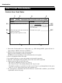
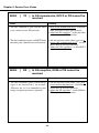
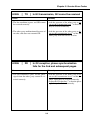
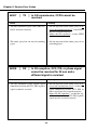
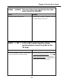
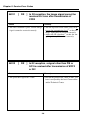
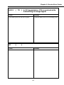
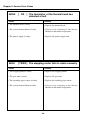
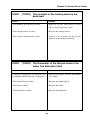
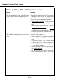
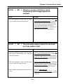
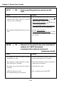
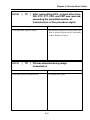
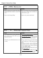
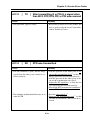
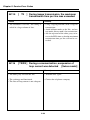
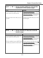

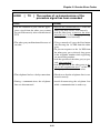
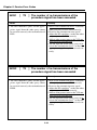
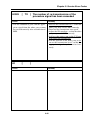

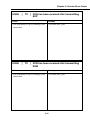


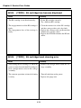
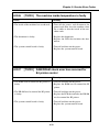
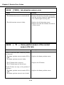
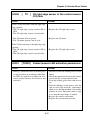
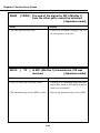
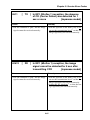
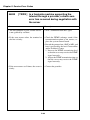
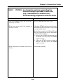
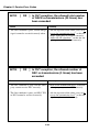
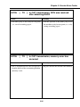
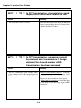
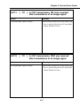
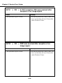
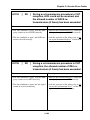
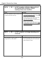
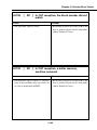
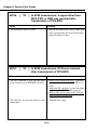
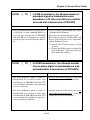
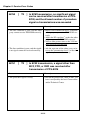
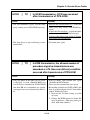
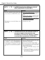
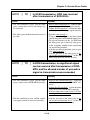
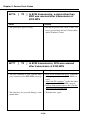
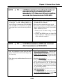
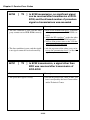

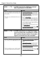
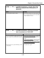
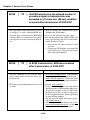
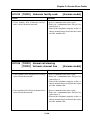
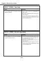
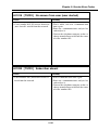

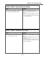
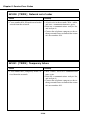
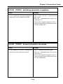
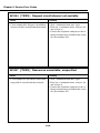
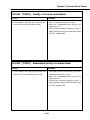


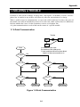
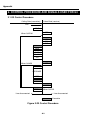
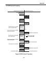
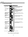
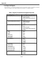
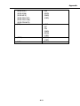

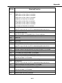
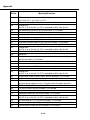
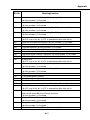
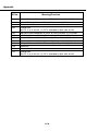
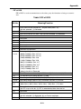
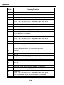
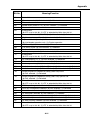
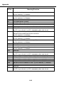
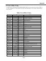
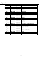
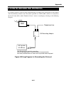
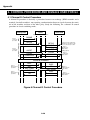
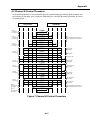
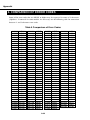


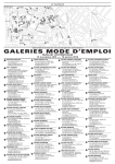
![取扱説明書[PDF:4.3MB]](http://vs1.manualzilla.com/store/data/006552141_2-6fd3fdf3ac0583a92c844693b198c134-150x150.png)
![ウェブブラウザ取扱説明書[PDF:541.4KB]](http://vs1.manualzilla.com/store/data/006614548_2-0209a95d758bb803bc6c578866930723-150x150.png)
![ライブビューワ取扱説明書[PDF:493.1KB]](http://vs1.manualzilla.com/store/data/006698008_2-588483502c13a112816087a276197b95-150x150.png)

![AGIVEN PROGRAM ]](http://vs1.manualzilla.com/store/data/005708142_1-ae1c6d6b32e7a9016e2dede042b38772-150x150.png)