1
28-MT STARTER
1M/128
OPERATING PRINCIPLES
When the engine starts and picks up speed, the overrunning
clutch allows the pinion to spin freely on the starter drive
shaft, preventing the engine from "driving" the starter.
When the start switch is released, current momentarily
flows from the solenoid contacts through the pull-in coil
and hold-in coil to ground. The current flow through the
pull-in coil is in the opposite direction to that in the holdin coil. This creates opposing magnetic fields that cancel
each other out. With the magnetic pull of the solenoid
cancelled, the plunger is released and the plunger spring
pushes it out of the solenoid, opening the solenoid contacts.
The shift lever pulls the pinion out of engagement with the
flywheel.
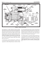
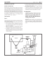
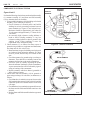
Figures 2, 3, and 4
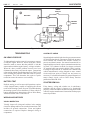
Figure 3 shows an electrical schematic for the starter when
it is at rest and when it is cranking the engine. The starter
is at rest when the engine is off and also when the engine
is running normally after starting.
When the start switch is closed, a small current flows
through the solenoid pull-in coil, field coil, and armature
windings to ground. A small current also flows through
the hold-in coil to ground. With both solenoid coils
energized, the plunger is pulled magnetically into the
solenoid. This action moves the shift lever and engages
the pinion with the engine ring gear, and moves the
contact disc to close the solenoid switch contacts. When
the switch contacts close, a large current flows through the
field coils and armature, causing the armature to turn and
crank the engine. This large current heats up the current
carrying conductors in the motor.
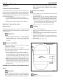
Figure 4 shows a typical wiring circuit with the starter
installed on the vehicle. One or more control switches may
be used in series with the start switch to prevent cranking
the engine unless certain system conditions are met. Refer
to the specific vehicle wiring diagram to see what other
cranking controls may be used. A typical example of a
control switch is a neutral safety switch that prevents
cranking unless the transmission is in neutral. In 12-volt
systems, the relatively low current in the "S" terminal
circuit may be handled directly by the start switch. However,
higher current levels in 24-volt systems always require that
the start switch operate a separate magnetic switch in the
"S" terminal circuit.
NOTICE: To avoid damage to the motor due to
overheating, do not crank the engine continuously
for more than 30 seconds at a time. If the engine has
not started within 30 seconds, allow the starter to cool
for at least 2 minutes before trying again.
START
SWITCH
SOLENOID
PLUNGER
SOLENOID
PLUNGER
SOLENOID
HOLD-IN
COIL
SHIFT
LEVER
SOLENOID
PULL-IN
COIL
START
SWITCH
SOLENOID
HOLD-IN
COIL
ENGINE
FLYWHEEL
SHIFT
LEVER
B
BATTERY
SOLENOID
PULL-IN
COIL
B
+
M
BATTERY +
M
-
-
SOLENOID
SWITCH
ENGINE
FLYWHEEL
CLUTCH
DRIVE
ASSEMBLY
AT REST
3
PAGE
4/96
SOLENOID
SWITCH
FIELD
COIL
FIELD
COIL
ARMATURE
ARMATURE
DURING
CRANKING
28-5105
Figure 3. Starter Electrical Schematic