1
is01040
of wire between the fender supports and the turn-signal
sockets.
1
8
is01054
7
2
7
4
3
3
1
6
6
5
5
2
4
1.
2.
3.
4.
5.
6.
7.
8.
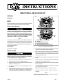
Screw
Lockwasher
Turn-signal housing support
Turn-signal housing
Grommet
Socket
Bulb
Lens
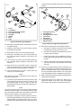
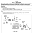
Figure 2. Stock Turn-Signal Removal
1.
2.
3.
4.
5.
6.
7.
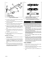
Turn signal housing
Threaded hole
Turn signal recess cover
Lock washer
Hex jam nut
Turn signal stud
Wiring exit hole
Figure 3. Rear Turn Signal Assembly To Stud
10. See Figure 2. Remove the lens and bulb from each rear
turn-signal housing.
19. Route the turn signal wires in the following sequence:
11. Carefully pry the socket out of each housing to remove
the sockets and grommets.
a.
See Figure 3. Insert the wires from the turn signal
housing through the wiring exit hole (7), and
12. Gently pull the wires out of the turn-signal housings.
b.
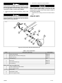
13. See Figure 4. Remove the four mid- and rear screws (2)
from the fender-support brackets on both sides of the
motorcycle.
(see Figure 3) through the threaded hole (2) in the
housing (1) from the inside.
c.
14. Loosen, but do not remove, the two forward screws (3)
from the fender-support brackets on both sides of the
motorcycle.
Position the recess cover (3) against the recess in
the turn signal housing, with the wires coming through
the hole.
d.
Insert the wires into the end of the turn signal bar (6),
and out the wire hole a short distance from the end
of the bar.
15. Gently lift the rear of the fender enough to remove the
screws (4) fastening the turn signals to the fender supports. Save the turn-signal housings for installation.
16. Lower the fender back into place. Loosely fasten the
screws (2) to the fender support.
NOTE
Apply liquid soap to the turn signal wires and use a thin wire
to pull wires through stud.
17. For each turn signal, thread the wires from the turn-signal
socket through the grommet, as shown in Figure 2, and
turn-signal assembly, as shown in Figure 6. Route the
wires starting through the threaded hole inside the turnsignal housing.
20. Screw the turn signal housing onto the threaded end of
the turn signal stud, being careful that the wires are not
twisted or damaged as the housing is assembled to the
bar. The lock washer will fit inside the hole in the recess
cover. Hand tighten the jam nut against the lock washer.
21. Apply Loctite® 243 (blue) to the stud threads between the
fender and fender support.
22. Thread each stud into the special nuts, taking care to
maintain the position of the notch in the note described
above. Torque each stud (6) to 18-22 ft-lbs (24-30 Nm).
NOTE
The notch cut into the special nut must be installed between
the fender and fender support, on the threads of the turn-signal
stud, and with the notched-side of the special nut facing the
fender and open toward the front of the motorcycle.
18. See Figure 3 and Figure 6. Route the wires for each turnsignal assembly through the rearmost hole in the fendersupport bracket, then through the special nut (7) and to
the inside of the fender. Allow about 6 inches (150 mm)
-J02427
2 of 4