1
is01038
is01037
3
1
4
1
2
5
1.
2.
3.
4.
5.
2
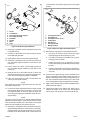
Fender support bracket
Screws
Forward screws
Turn signal screws
On FLSTF, FLSTS only
3
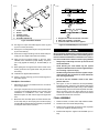
1. Stripped wire ends inserted into connector
2. Wire ends crimped in connector
3. Connector after heat has been applied
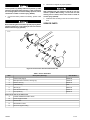
Figure 4. Hardware Removal
23. See Figure 4. Torque the fender-support screws (2) and
(3) to 21-27 ft-lbs (28-37 Nm).
Figure 5. Sealed Butt-Splice Connections
24. See Figure 6. Loosely fasten the jam nuts (5) and washers
(4) onto the studs (6).
25. Screw the turn-signal housings onto the studs while preventing the turn-signal socket wires from twisting.
26. Align the rear turn-signal housing so the lens, when
installed, faces rearward for proper visibility. Torque the
jam nut (5) against the housing to 96-120 in-lbs (11-13
Nm).
27. While pulling the turn-signal wires into the inside of the
fender, guide each turn-signal socket and grommet into
its housing.
28. Install the turn-signal bulbs and lenses.
29. Fasten a chrome hole plug (1) into the remaining hole in
the fender support.
Be sure to follow manufacturer's instructions when using
the UltraTorch UT-100 or any other radiant heating device.
Failure to follow manufacturer's instructions can cause a
fire, which could result in death or serious injury. (00335a)
•
Always keep hands away from tool tip area and heat
shrink attachment.
•
Avoid directing the heat toward any fuel system
component. Extreme heat can cause fuel ignition/explosion resulting in personal injury.
•
Avoid directing heat toward electrical system components other than the connectors on which heat-shrink
work is being performed.
•
Be sure to turn the "ON/OFF" switch to the "OFF"
position after use.
4.
See Figure 5. Use an UltraTorch UT-100 (HD-39969),
Robinair Heat Gun (Kent-Moor Part Number HD-25070)
with Heatshrink Attachment (HD-41183), or other suitable
radiant heating device to heat-shrink the jacket of the buttsplice connector to the wire. Apply heat from the center
of the crimp outward to the crimp ends until the sealant
encloses both ends of the connector.
Butt-Splice Connections
1.
Strip 3/8 inch (10 mm) of insulation from the cut ends of
the turn-signal wires.
2.
See Figure 5. Splice each set of cut wires into butt splice
connectors. Connect Black to Black in one connector, and
Violet/Brown to Violet/Brown in the other connector.
Repeat the splice for both left and right turn-signal wire
sets.
3.
Match the color of the butt-splice connector with the color
of the crimp cavity on the crimping tool. Use the crimping
tool (Kent-Moore Part Number HD-38125-8) or equivalent
to crimp the wires into the connector.
-J02427
FINAL ASSEMBLY
1.
Fasten the wires, in conduit, to the clips inside the fender.
2.
Route the wires into the tail-lamp housing.
3.
Fasten the turn-signal-wire connectors to their respective
connections inside the tail-lamp housing.
4.
Install the tail-lamp lens. Tighten to 20-24 in-lbs. (2.3-2.7
Nm).
3 of 4