1
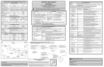
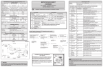
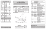
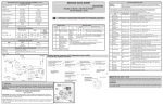
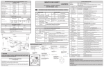
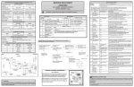
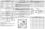
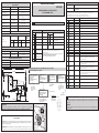
SERVICE DATA SHEET
A01544401
PERFORMANCE DATA NO LOAD & NO DOOR OPENINGS AT 37°/0°
CONTROL SETTING
Type A with Run / Start Capacitor
65°F (18°C) Ambient
90°F (32°C) Ambient
90 to 100%
100%
-5° to 2°F
(-20° to -17°C)
-1° to 3°F
(-18° to -16°C)
34° to 39°F
(1° to 4°C)
34° to 39°F
(1° to 4°C)
-2 to 6 psig
(-14 to 41 kPa)
-2 to 6 psig
(-14 to 41 kPa)
Operating Time
Freezer Temperature
Refrigerator Temperature
Low Side Pressure
High Side Pressure
(last 1/3 cycle)
85 to 105 psig
(586 to 724 kPa)
Wattage (last 1/3 cycle)
Base Voltage
Test
Blank UI display, no lights illuminated.
Second Screen
--
All LED lights on UI illuminated.
--
Third Screen
--
Blank UI display, no lights illuminated.
50 to 70
2
Defrost Heater
Press power on-off
Defrost heater on when “on”; off when “off”.
.7 to .9
3*
FF Light
(Incandescent Models)
Press power on-off
FF lights on when “on”; off when “off”
Heater
IMPORTANT: PLEASE RETURN THIS SHEET TO ITS ORIGINAL LOCATION.
Defrost
Heater
Termination
Cabinet Size:
Cut-in
Cut-out
Watts
Ohms
Cut-out
110°F
(43.3°C)
135°F
(57.2°C)
500
26.5
39°F
(4°C)
Electronic Timer - (ADC) Defrost 24 minutes every 6-96 hours of compressor run time.
Watts
RPM
Amps
3.1
1100 CW
Opposite Shaft
0.03 Running
FREEZER ICE MAKER SPECIFICATIONS
Opens at 48°F ( 9°C), Closes at 15° F ( -9°C)
Heater Voltage
115 vac
LINE
NEUTRAL
POWER
ICE MAKER
MOTOR
--
OP
Open FF Thermistor
OP
--
--
SH
SH
--
SY
CF
THERMOSTAT
NO
BLU
BLK
C
MOLD HEATER
165 WATTS
NO
GRN / YEL
P-1
C
MOLD
MOUNTING
PLATE
ICE MAKER
NC
RED
NC
C
FZ
FF
Manual Defrost
d
F
Open FZ Thermistor
Display / Showroom
77
77
Shorted FF Thermistor
Sabbath
Sb
Sb
Shorted FZ Thermistor
System Diagnostic
UI to Main Control Board
communication failure;
on start up
SY
CE
UI to Main Control Board
communication error;
after a period in operation
SY
EF
Evaporator Fan Failure
→
Check at the connector from the power cord
harness into the inverter board, located in
the machine compartment.
(PUR and WHT wires)
→
NC
SHUTOFF
SWITCH
YELLOW
WATER FILL
SWITCH
FZ Light
Press power on-off
With FZ door open, FZ lights on when “on”, off when “off”
VCC Condenser Fan
Press power on-off
Fan running when “on”; stopped when “off”
41*
Perfect Temp
Drawer (PTD)
Press power on-off
PTD UI illuminated when “on”; off when “off”
FZ UP and FF DOWN /
Power-on-Reset (POR)
13*
FF Light
(LED Models)
Press power on-off
FF lights on when “on”; off when “off”
FZ DOWN and FF UP / same to deactivate
38
VCC Compressor
Press power on-off
Compressor running when “on”; stopped when “off”
FZ UP and FZ DOWN / FF UP to deactivate
15
Evaporator Fan
Press power on-off
Stopped when “off”. Listen for speed change from “LO” to “HI”.
20*
FZ Light
(LED Models)
Press power on-off
FZ lights on when “on”, off when “off”
22
Damper
Press power on-off
With inspection mirror, observe damper open when “OP”; closed when “CL”
23
FF Door
Open/close FF door
“CL” on UI when door closed; “OP” when open
24
FZ Door
Open/close FZ door
“CL” on UI when door closed; “OP” when open
29
FF Thermistor
Activates automatically
UI shows temperature sensed by FF thermistor; pass if within 10°F of
temperature measured with gauge at FF thermistor location.
“OP” if open; “SH” if short
30
FZ Thermistor
Activates automatically
UI shows temperature sensed by FZ thermistor; pass if within 10°F of
temperature measured with gauge at FZ thermistor location.
“OP” if open; “SH” if short
33
Ambient Thermistor
@ Main Board
Activates automatically
UI shows temperature sensed at main board; pass if within +20°F/-10°F
of temperature measured with gauge at main board location.
“OP” if open; “SH” if short
39
Evaporator
Thermistor
Activates automatically
UI shows temperature sensed by evaporator thermistor; pass if within
10°F of temperature measured with gauge at evaporator thermistor location. “OP” if open; “SH” if short
34*
Ambient Thermistor
@ UI
Activates automatically
UI shows temperature sensed at UI; pass if within +20°F/-10°F of temperature measured with gauge at UI location. “OP” if open; “SH” if short
0-
Firmware
Parameters
Press power on-off
Displays digit sequence; record
2-
Main Board
Firmware
Press power on-off
Displays digit sequence; record
4-
UI Firmware
Press power on-off
Displays digit sequence; record
FF UP and FF DOWN / same to deactivate
No FF or FZ
display, all UI
LEDs on.
Notes:
• Always check for pin back-outs, pinched or damaged wires before
replacing components.
• Determine whether failure is caused by the component, main control board or wiring.
Contact TID before replacing main control board.
• Refer to Service Manual for additional information.
yes
Check at Inverter Board on
Compressor
(BLK and RED wires)
•
•
→
yes
Is Inverter Board receiving 10-15
VAC and 1-5 VDC from Main
Control Board?
no
P-4
WATER VALVE
RED
Mode
9*
12
Activate/Deactivate
(press for up to 10 sec. simultaneously)
Variable Capacity Compressor (VCC) Diagnostics (select models)
If test 38 fails, diagnose as follows:
LT. BLUE
NO
Interpretation
FF
Is Inverter Board receiving 115 VAC
from power supply?
RED
HOLD
SWITCH
ICE MAKER
BLK
THERMAL
CUT-OUT
LT. BLUE
ICE MAKER
BRN
BLK
P-3
SPECIAL MODES
Display
FZ
CONDENSER FAN MOTOR
Thermostat
Passing result
--
ERROR CODES
115 vac (127 vac max)
To activate test:
--
Display
Electrical
Press FF UP for up to 10 sec. Diagnostic Mode will automatically deactivate after 5 min. of inactivity.
Note: Silence alarm.
First Screen
DEFROST SPECIFICATIONS
27’ & 28’ SD, 22’ CD
Deactivate:
• Tests marked with “*” may not be applicable to this unit and will not be displayed in System Diagnostic Mode.
• Tests displayed in diagnostic mode but not described below are for internal purposes only; advance through.
• View UI display for “on,” “off,” “CL,” “OP,” “SH,” “LO,” “HI” or numerical results of tests.
• Listen for operating sounds; feel for heat or air flow as appropriate to determine results of tests.
BOTTOM FREEZER - R134a
115 vac (127 vac max)
Thermal Cutout
Press FZ UP and FZ DOWN for up to 10 sec. simultaneously. Press FF UP to advance through
tests.
--
.4 to .8
Amps (running)
FREEZER ICE MAKER - AUTOMATIC DEFROST
120 to 135 psig
(827 to 931 kPa)
30 to 50
SYSTEM DIAGNOSTIC MODE
Activate:
Is resistance across all winding
pairs equal?
no
Check voltage supply.
Check and repair power
cord harness wiring and
connections.
Remove inverter box from the
compressor and check resistance
across compressor winding pairs as
shown.
Check at Main Control Board
(BLK/WHT and RED/BLK wires)
Is Main Control Board sending
10-15 VAC and 1-5 VDC to
Inverter Board?
yes
P-2
Identify and repair damaged wires or
poor connections between Main Control
Board and Inverter Board.
yes
Check connections from Inverter
Board to Compressor
Are connections from Inverter
Board to Compressor intact?
no
Replace Compressor and
Inverter Board.
→
→
no
no
Identify and repair damaged
wires or poor connections
between Inverter Board and
Compressor.
yes
Replace Main Control Board.
VCC Resistance Check
Check resistance between terminals 1 and
2, 2 and 3, 3 and 1.
If all resistances are equal,
compressor is operative.
Replace Inverter Board
IMPORTANT SAFETY NOTE
The information provided herein is designed to assist qualified repair personnel only. Untrained persons should
not attempt to make repairs due to the possibility of electrical shock. Disconnect power cord before servicing
this appliance.
IMPORTANT
CAUTION
All electrical parts and wiring must be shielded from torch flame. DO NOT allow torch to touch insulation;
it will char at 200°F and flash ignite (burn) at 500°F. Excessive heat will distort the plastic liner.
Water Fill
Adjustment
If any green grounding wires are removed during servicing, they must be returned to their original position and
properly secured.
Motor
Gear
TU
(Where Applicable)
Test Cycling: Remove cover by inserting screwdriver in notch at bottom and prying cover from housing. Use screwdriver to rotate motor gear counterclockwise until holding switch circuit is completed. All components of ice maker
should function to complete the cycle.
Water Fill Volume: The water fill adjustment screw will change the fill time. One full turn is equal to 20cc (.68 oz.).
The correct fill is 102 to 130cc (3.4 to 4.3 oz.). When a water valve is replaced, the fill volume must be checked.
R
N
FREEZER ICE MAKER INFORMATION
Mounting
Plate
Screws
Mounting
Plate
Screw
Timing
Gear
PTD MODELS ONLY
PTD ERROR CODES:
PTD MODELS ONLY
PTD USER
INTERFACE
BOARD
1
2
J2
3
4
RED/BLACK
PINK/WHITE
WHITE/PINK
PIN 1
PIN 2
PIN 3
PIN 4
PIN 5
PIN 6
PIN 7
PIN 8
THERMISTOR T1
(PTD DRAWER)
TO THE TWO LEDS
IN THE PTD COVER
BLACK/WHITE
GRY
ORN
CONNECTION TO
PTD COVER
PTD MODELS ONLY
BLACK
RED/YELLOW
BROWN/YELLOW
BLACK/YELLOW
WHITE/YELLOW
WHITE
WHITE
TO LED
POWER BOARD
(J2)
1
J8
2
1
2
J6
3
4
PTD
MAIN PCBA
1
2
J2
3
4
1
2
J11
3
4
PTD DRAWER
HEATER
PTD DRAWER
HEATER THERM.
LT BLUE
3
J3 2
LT BLUE
1
1
2
3
4 J7
5
6
7
1
2
3
4
2X - OPEN NTC,
WHERE THE "X" IS:
1 FOR THE PTD DRAWER NTC
2 FOR PTD FREEZER AIR NTC
3X - SHORTED NTC,
WHERE THE "X" IS:
1 FOR THE PTD DRAWER NTC
2 FOR PTD FREEZER AIR NTC
PTD
HEATER
GROUND
BLK/PNK
GRN/YEL
YEL/BLK
LT. BLU
POWER CORD
CE - LOSS OF COMMUNICATION
BETWEEN UI AND MAIN PCB
HI F - UCL OVER TEMP
TIME OUT EXCEEDED
PTD MODELS ONLY
BASE PLATE
GROUND
+ J2-7
Z1-1
-
Z1-3
Z2-1
DC SIDE
CAB. GROUND
+12V DC
LINE
PIN 8
RL2
RL8
+5V DC
LT.BLU/BLK
BLK/PNK
FLIP MULLION COVER
RIGHT HINGE
GROUND
J1-1
NEUTRAL
FF LEDS
MC1
LT. BLU
LT. BLU
LT.BLU/BLK
PIN 8
MB1
LH1
RH2
RED
COMPRESSOR
CONTROL SIGNAL
RED/BLK
1
BLK
BLK/WHT
2
YEL/BLK
LT. BLU
AT1
RED/YEL
PIN 6
RED/YEL
BACK VIEW
BRN/YEL
PIN 5
BRN/YEL
BLK/YEL
WHT/YEL
BLK/YEL
PIN 3
WHT/YEL
PIN 2
MB1
YEL/PNK
FREEZER DOOR
SWITCH
(DOOR OPEN)
PIN 4
YEL/PNK
BLK/ORN
BLK
PIN 5
YEL/PNK
YEL/PNK
MC1
NEUTRAL
+12V DC
U2 (SSR1)
GND
TO PERFECT TEMP
DRAWER HOUSING
11
12
1
J2 6
J3 6
YEL/BLK
YEL/RED
2
1
2
3
4
J1
RED
TYPICAL LED CONNECTOR
CONDENSER FAN
+12V DC
YEL
NEUTRAL
OUT1A
OUT1B
RL6
1
J2 5
2
OUT2A
BLK
LT. BLU
BRN
BLK
PIN 2
BLK/ORN
OUT2B
12
J5
8
+5V DC
FREEZER DOOR
SWITCH
(DOOR OPEN)
Z1-1
ZONE 1
LEFT LEDS
4
FREEZER
ICE MAKER
(SEE FZ ICE
MAKER DIAGRAM)
ERF2500++ISO
REFRIGERATOR
CONTROL
YEL/PNK
THERMAL
CUT-OUT
FREEZER
EVAPORATOR
HEATER
3
1
LED
-
-
-
BLK/PNK 2
BLK/WHT 1
Z2-2
+
LED
+
-
BLK/WHT 2
WHT/PUR 1
Z2-1
BOARD VIEW
2
4
2
4
1
LED POWER
BOARD
9
7
9
7
3
1
2
2
1
1
RL3
RL6
1 1
1
2
1
Z4-2
+
LED
Z4-3
LED
-
+
2 WHT/GRN
1 BLK/BRN
J4
LED LIGHTS
RL8
2 2
ZONE 4
FF DOORS AND
FRONT OF FREEZER
+
J8
AMBIENT
TEMP
SENSOR
RL9
J3
Z4-1
ONLY ON MODELS
WITH PTD
-
-
12
RL5
1
RH2
RH1
11
J6
J2
1
1
MC1
3
LATCH
CATCH
-
1
7
1
3
LED
7
1
3
1
+
LED
RL2
1
AT1
ZONE 3
PTD LEDS
BLK/ORN 1
BLK/BRN 2
3
9
RL1
Z3-1
+ -
9
1 4
WHT/RED 1
BLK/ORN 2
3
J11
BLK/GRY
ORN
GRY 2
BLK/GRY 1
Z3-2
J10
GRY 2
ORN 1
2
1
GRY 7
ORN 8
2 4
1 3
ZONE 2
RIGHT
LEDS
LED
+
LED
-
2 WHT/BRN
1 BLK/PUR
Z1-3
J1
Z2-4
BLK/GRN 2
BLK/PNK 1
Z2-3
Z1-2
BEHIND FRONT
LEFT ROLLER
J9
MB2
+
+
2 BLK/PUR
1 BLK/BLU
COIL COVER
GROUND
5
RH2
LED
GRN/YEL
+5V DC
LH1
J2
YEL/BLU
2
BOARD-MOUNTED
AMBIENT THERMISTOR
5
5
1
CATCH
YEL/PNK
MB2
6
2
LATCH
PIN 3
PIN 4
7
3
LH1
YEL/BLU
PIN 1
8
4
1
FREEZER ICEMAKER
WATER VALVE
FRONT INSIDE
VIEW
MB1
LED POWER
J2
SUPPLY
LT. BLU
MAIN INLET
WATER VALVE
5
6
J5
3
4
MB2
J1-1
LED LIGHTS
LT. BLU
LT. BLU
1
J8
2
AT1 & MB1
J1-4
J1-3
+12V DC
LINE
12V DC
DAMPER
MOTOR
1
2
3
4
-
BRN/WHT
J2-1
J2-4
NEUTRAL
LED
PIN 3
1
-
FREEZER POWER
(120V AC)
FRESH FOOD
POWER (120V AC)
MULLION HEATER
5
PIN 1
2
PIN 1
5
1
RED/WHT
3
5
YEL/WHT
PIN 2
4
Z4-3
2
PIN 2
RH1
J2-2
PIN 6
BLK/PNK
GRN/YEL
5
6
7
8
J4
9
GRN/YEL
+
-
BLK/ORN 1
BLK/BRN 2
PIN 1
GRY/BLK
J1-3
PIN 3
FREEZER
LEDS
BLK/GRN 2
WHT/BLK 1
1
GRY/BLK
7
J3 2
4
YEL/BLK
J1-4
PIN 2
J2-6
Z4-2
-
MB1
PIN 7
YEL/RED
-
+ J2-3
Z4-1
RIGHT DOOR
FLANGE
LED
AT1
PIN 4
RL4
+5V DC
MC1
J2 3
J2-5
+
2
RL5
LED POWER
BOARD
GRN/YEL
WHT/BRN 8
WHT/BLU 7
WHT/BLK 6
WHT/PUR 5
WHT/GRN 4
WHT/RED 3
2
GRY
1
ORN
FRESH FOOD
SENSOR
GRY/WHT
1
+5V DC
BASE PLATE
GROUND
BLK
BLK/BLU 2
WHT/BLU 1
FREEZER
SENSOR
2
GRY/WHT
Z3-2
+
GRY/YEL
1
7
8
9
J6
10
11
12
12 VDC
GRN/YEL
GRN/YEL
WHT/RED
BLK/ORN 1
GRY/YEL
2
1
J1 2
3
Z3-1
1
FREEZER
EVAPORATOR
SENSOR
EVAPORATOR
FAN (DC)
RH1
NEUTRAL
+5V DC
LT. BLU
Z2-4
1
RED
VARIABLE SPEED
COMPRESSOR/ INV.
CONTROL SIGNAL
RED/BLK
BLK/WHT
LEFT DOOR
LH1
INLINE CONNECTOR ABBREVIATION KEY
ABBR.
EXPLANATION
AT1 9 PIN CONNECTION AT AIR TOWER
5 PIN CONNECTION AT THE LEFT
LH1
DOOR UPPER HINGE
9 PIN CONNECTION IN THE MAIN
MB1 BOARD HOUSING BEHIND THE TOE
GRILLE
4 PIN CONNECTION IN THE MAIN
MB2 BOARD HOUSING BEHIND THE TOE
GRILLE
9 PIN CONNECTION IN THE
MC1 MACHINE COMPARTMENT TO THE
LEFT OF THE COMPRESSOR
2 PIN CONNECTION WITH THICKER
RH1 WIRES AT THE RIGHT DOOR UPPER
HINGE
2 PIN CONNECTION WITH SMALL
RH2 WIRES AT THE RIGHT DOOR UPPER
HINGE
COMM.
+
Z2-3
LT. BLU
GND
J2-8
Z2-2
BLK
BLK
PIN 1
J2
PIN 3
PIN 4
PIN 5
AC SIDE
POWER
LT. BLU
PIN 5
USER
INTERFACE
3
2
1
WHT
1
2
J9
3
4
COMPRESSOR
GROUND
PIN 4
BLK
LED POWER
PCBA
Z1-2
LO F - LCL UNDER TEMP
TIME OUT EXCEEDED
RIGHT DOOR
4
3
PTD
DAMPER 2
1
LED
FLEX CABLE TO KEYPAD
PTD
FAN
J3
9X - SHORTED KEY/BUTTON,
WHERE THE "X" IS:
1 FOR "ON/OFF"
2 FOR "+"
3 FOR "C/F"
4 FOR "-"
5 FOR "LOCK"
6 FOR "V" DOWN ARROW KEY
7 FOR "^" UP ARROW KEY
RIBBED
(NEUTRAL)
PTD USER INTERFACE
KEYPAD ASSEMBLY
RED
NON-RIBBED
(LINE)
PTD COVER
1
1
J7
U2 RL4
RL7
J5
1
Wire Diagram A01536601