1
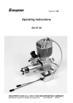
00-4036
Instruction Manual
Models
D1 125 c.c. Bantam
D3 150 c.c. Bantam Major
D5 150 c.c. Bantam Major
Instruction Manual
for
D Models
>
>
>
>
>
B.S.A. MOTOR CYCLES LTD., BIRMINGHAM 11
Telephones: – – – Birmingham, VICtoria 2381
Telegrams and Cables: “SELMOTO,” Birmingham
B.S.A. Motor Cycles Ltd., reserve the right to alter the designs or any
constructional details of their manufactures at any time without giving notice.
xx
Copyright B.S.A. Co. Ltd.
B.S.A. Press (February 1967)
Reproduced August 2003 by Tom Seale
MC.1360
This Instruction manual is intended to acquaint the B.S.A. owner
with details of the controls, general maintenance and technical
data which may be required for normal operation of the machine.
It does not contain the information necessary to carry out
complete stripping for major overhauls, but if any owner feels he
is competent to carry out this type of work, a service manual and
an illustrated, priced, spares catalogue for this machine can be
obtained from his B.S.A. spares stockist or local distributor.
Owners in the British Isles can obtain these publications
direct from B.S.A. Motor Cycles Ltd., Service Department,
Armoury Road, Birmingham 11. Always quote full engine and
frame numbers when ordering these publications.
2
FIG. 1. The Controls.
3
CONTENTS
Pages
AIR CLEANER
...
...
...
...
...
...
...
...
...
17
BRAKES
...
...
...
...
...
...
...
...
...
23
CARBURETTER ...
...
...
...
...
...
...
...
...
17
FRONT CHAIN
...
...
...
...
...
...
...
...
...
17
REAR CHAIN
...
...
...
...
...
...
...
...
...
20
CLEANING...
...
...
...
...
...
...
...
...
...
9
CLUTCH
...
...
...
...
...
...
...
...
...
20
...
...
...
...
...
...
...
...
...
6
CYLINDER HEAD AND BARREL REMOVAL ...
...
...
...
12
DRIVING ...
...
...
CONTROLS
...
...
...
...
...
...
...
...
...
7
...
...
...
...
...
...
...
...
11
ELECTRICAL EQUIPMENT ...
...
...
...
...
...
...
27
FORKS
DECARBONISING
...
...
...
...
...
...
...
...
...
...
24
GEARBOX ...
...
...
...
...
...
...
...
...
...
22
HUBS
...
...
...
...
...
...
...
...
...
22
IGNITION TIMING
...
...
...
...
...
...
...
...
10
LUBRICATION CHART
...
...
...
...
...
...
...
18–19
LUBRICATION SYSTEM
...
...
...
...
...
...
...
10
ROUTINE MAINTENANCE ...
...
...
...
...
...
...
9
REAR SUSPENSION
...
...
...
...
...
...
...
...
26–27
RUNNING-IN
...
...
...
...
...
...
...
...
8
SPARKING PLUG
...
...
...
...
...
...
...
...
15
STEERING HEAD
...
...
...
...
...
...
...
...
25
TECHNICAL DATA
...
...
...
...
...
...
...
...
5
TRANSMISSION ...
...
...
...
...
...
...
...
...
17
WHEEL REMOVAL (FRONT)
...
...
...
...
...
...
22
WHEEL REMOVAL (REAR) ...
...
...
...
...
...
...
22
WIRING DIAGRAM (DIRECT LIGHTING SET) ...
...
...
...
31
WIRING DIAGRAM (BATTERY SET)
...
...
...
32
...
...
...
4
...
TECHNICAL DATA
Engine Number—on top of crankcase below cylinder.
Frame Number—at top of steering head tube.
ENGINE:
Model D1
Model D3
Model D5
123 c.c
52 mm.
58 mm.
6.5 : 1
.009 in.
.013 in.
L10S (L7)
.018 in.
.020 in.
148 c.c
57 mm.
58 mm.
6.4 : 1
.009 in.
.013 in.
L10S (L7)
.018 in.
.020 in.
174 c.c
61.5 mm.
58 mm.
7.4 : 1
.009 in.
.013 in.
L10S (L7)
.018 in.
.020 in.
...
...
...
...
7.0
11.7
22.0
3
7.0
11.7
22.0
3
6.48
10.74
20.2
3
...
...
...
...
...
...
50
117
17
15
38
47
50
121
17
15
38
47
50
121
17
16
38
46
...
...
...
...
...
...
1¾ gall.
See page 18
¾ pint
1¾ gall.
See page 18
¾ pint
2 gall.
See page 18
¾ pint
Rim size (front)
...
(rear) ...
...
Tyre size (front)
...
(rear) ...
...
Tyre pressure (front)
(rear) ...
Brake size—diameter ...
wide
...
...
...
...
...
...
...
...
...
WM1–19
WM1–19
2.275–19
2.75–19
16 p.s.i.
22 p.s.i.
5 in.
⅝ in.
WM1–19
WM1–19
2.75–19
2.75–19
16 p.s.i.
25 p.s.i.
5 in.
⅝ in.
WM1–18
WM1–18
3.00–18
3.00–18
16 p.s.i.
24 p.s.i.
5 in.
⅞ in.
Capacity ...
...
...
...
Cylinder bore ...
...
...
Stroke ...
...
...
...
Compression ratio
...
...
Piston ring gap (minimum) ...
(maximum)
Sparking plug ...
...
...
Plug points gap (minimum) ...
(maximum)
TRANSMISSION:
Gear ratios—top
...
second ...
first
...
Clutch—friction plates
Chain size and pitch:
(front) ⅜ × .250 in.
(rear) ½ × .335 in. ...
Teeth on—engine sprocket
gearbox sprocket
clutch sprocket
rear chainwheel
CAPACITIES:
Fuel tank ...
...
Petroil mixture ...
Gearbox ...
...
WHEELS:
5
TAKING OVER THE MACHINE
Before running the machine make sure that the fuel tank contains the correct mixture
of oil and petrol, that the gearbox is properly topped up with oil and that the battery
(when fitted) is filled and charged. (See appropriate chapters for filling instructions).
Normally these preparations will be carried out by the dealer who is selling the
machine and the new owner has only to arrange the controls to his liking and the
machine is ready for the road.
The Controls
The new rider should make sure that he is quite familiar with all the controls before
attempting to ride the machine. Most of the controls are adjustable and should be
positioned so that they can be reached without moving the hands from the grips or the
feet from the footrests. Handlebars should be adjusted so that a comfortable and
natural riding position is achieved. Make sure that the bolts retaining the handlebar
clamps are tight after completing any adjustment. Badly positioned controls cause
poor control of the machine and will bring discomfort on long journeys.
HANDLEBAR CONTROLS
Twist Grip
Mounted on the right handlebar it controls the throttle opening. To open the throttle
(i.e. to increase the engine speed) turn the grip so that the top moves towards the
rider. Full movement is about a quarter of a turn.
Front Brake
Hand lever mounted on the right handlebar in front of the twist grip. Squeeze the
lever towards the bar to operate the brake.
Clutch
Hand lever mounted on the left handlebar in front of the grip. Squeeze the lever
towards the bar to free the clutch, i.e. to disengage the drive between the engine and
the rear wheel.
Horn (Battery Equipment)
The horn button is mounted on the right handlebar on the top of the front brake lever
bracket.
Headlamp Dipper Switch
On the left handlebar attached to the rear of the clutch lever. It controls the switching
from main to dipped headlamp filaments.
FOOT CONTROLS
Rear Brake
This is a toe pedal on the left-hand side of the machine and it OPERATES THE REAR
BRAKE ONLY.
Gearchange Pedal
On the right-hand side there are two pedals one of which projects forward, this being
the gearchange pedal. To engage first gear from the neutral position, the pedal is
moved downwards. To change to a higher gear move the pedal upwards. To change
to a lower gear depress the pedal. The pedal automatically returns to central position,
ready for next gearchange.
6
Kickstarter Pedal
This is the other pedal on the right-hand side of the engine. Depression of the pedal
rotates the engine.
OTHER CONTROLS
Petrol Tap
This is located under the rear end of the tank. To turn on the petrol, pull the serrated
button out and lock in position by turning anti-clockwise. To turn off the petrol, turn
the button in a clockwise direction and push in.
Lighting Switch
This is operated by a switch on the headlamp, and has three positions—OFF, LOW,
and HEAD respectively. The LOW position is also for use when the machine is
stationary. On direct lighting models the parking bulb draws its current from a dry
battery accommodated in the headlamp behind the reflector.
On battery lighting models turn the lighting switch to LOW if the battery is
discharged as this will deliver the maximum charging current to the battery when the
engine is running.
Carburetter Tickler
This is a small plunger in the top of the carburetter float chamber. Pressing it down
pushes down the float and frees the needle valve thus permitting the carburetter to
receive excess petrol.
Steering Lock
Mounted underneath the bottom fork yoke. To operate the lock turn the forks to the
left then turn the key in the lock to release the plunger. This prevents the machine
being driven or wheeled.
DRIVING
To Start the Engine
Set the gear in neutral (i.e., between the first and second gear positions).
If cold, first depress the carburetter tickler momentarily and close the strangler.
Open the twist grip control a small amount and give the kickstarter a vigorous kick
downwards, whereupon the engine should fire at once.
During normal running the strangler must always be kept fully open and it
should be opened immediately the engine fires, or should the weather be cold, at the
earliest possible moment.
NOTE:—While it is necessary to close the strangler when starting from cold, this
may not be necessary when the engine is warm and should certainly not be so if the
engine is restarted after a short wait only.
To Stop the Engine
Close the throttle and disengage the clutch. If the engine does not stop it indicates
that the throttle is not closing properly.
To Engage First Gear
Declutch and move the gearchange pedal downwards to its limit. If difficulty is
experienced in engaging first gear when stationary, rock the machine backwards and
forwards maintaining slight pressure on the gearchange pedal, until the gear is felt to
engage.
7
To Move Off
Open the throttle slightly and gently release the clutch lever. As the clutch engages
open the throttle a little further.
To Change Gear (Up)
Disengage the clutch and immediately thereafter raise the gearchange pedal upwards
to its limit, at the same time easing the throttle back. Engage the clutch and re-open
the throttle together immediately after changing.
To Change Gear (Down)
Disengage the clutch, open the throttle slightly, and press the gearchange pedal
downwards to its limit, all these operations being performed in rapid succession.
Re−engage the clutch immediately.
NOTE:—Violent pressure on the gearchange pedal is neither necessary nor
desirable.
To Select Neutral
Neutral is situated between first and second gear. To select neutral from first gear,
with the clutch withdrawn lift the gearchange pedal gently until it is felt to click into
the neutral position. If the lever is lifted up too far it will travel through to second
gear. To select neutral from second gear push the lever down until it is felt to click
into position.
Riding Hints
Avoid violent acceleration and braking, particularly on wet roads. Always use both
brakes together and apply them smoothly and progressively. Try to anticipate the
need to change gear or to brake so that your riding is not jerky or untidy. Maintain a
natural riding position as this provides maximum control and prevents discomfort on
long journeys.
RUNNING-IN
The rider who has just purchased a new machine for the first time will do well to
remember that all the hidden working parts are just as new as the enamel and plating
which he can see, and that they must not be overloaded until they are well run-in.
This running-in is really the most important period in the life of the engine, and
the handling you give it during the first 1,000 to 1,500 miles will determine what sort
of service it is going to give you later.
It is advisable not to exceed half-throttle in any gear during the first 500 miles.
The model’s maximum will then not disappoint you. If you try to put it through its
paces too soon you will run the risk of seizure and other troubles which may have a
lasting effect on the lifetime of the engine, and, in any case, until it is really well runin it will not be at its best.
Avoid sudden and sharp acceleration, especially when the engine is not pulling
under load.
Do not force it up hills in top gear, when a change down would ease the load.
Carry out the periodical maintenance details described later with faithful
regularity.
8
After the first 250 miles (400 km.), remove the smaller of the two screwed plugs
from the bottom of the crankcase and drain out any oil which may have accumulated
there. With the petroil lubrication system employed there is never a considerable
quantity of liquid oil in the crankcase, but whatever oil there is should be drained
away, and this is preferably done while the engine is warm immediately after a run,
as the oil will flow more freely and carry with it any foreign matter which may have
found its way into the crankcase during the running-in process.
Make certain on replacing the plug that it is made really tight in order to prevent
loss of crankcase compression.
During the running-in period the gearbox should also be drained and flushed out
and this is preferably done at the same time as the crankcase.
Information regarding the correct grades of oil is given in the chart on page 18.
ROUTINE MAINTENANCE
To keep the machine in good condition and provide trouble-free running,
maintenance must be regularly carried out. The following list of items requiring
regular attention will serve as a guide to the periods between servicing and the
method of carrying out the various adjustments will be found under the appropriate
headings in the later chapters.
Weekly
Check tyre pressures and remove any embedded stones or pieces of metal.
Oil brake pedal pivot and all exposed joints and cables.
Monthly
Examine the battery (when fitted) and top up if necessary. More frequent
examination is advisable in a hot climate.
Every 300 Miles
Check oil level in gearbox and top-up if necessary.
Every 1,000 Miles
Grease hubs, steering head, clutch operating mechanism, central stand, front
forks (D1) and rear suspension (plunger type).
Oil brake cam spindles and saddle nose bolt.
Check rear chain adjustment.
Every 2,000 Miles
Change the oil in the gearbox.
Grease the speedometer drive.
Check tightness of all nuts and bolts.
Every 3,000 Miles
Check contact breaker adjustment and grease the felt pad.
Cleaning
Obviously regular and thorough cleaning will keep your machine looking smart and
will help to retain both its new appearance and value. But it helps also to lengthen its
life and maintain efficiency if the cleaning process is carried out correctly.
Take special care to prevent dust and grit from working into such parts as hubs,
carburetter, magneto, brakes and gearbox.
9
To rub dry and caked mud from the frame, tank and mudguards means that the
enamel on these parts will be subjected to an abrasive action which will quickly
destroy the polish. Soak the mud first, and then float it off with copious supplies of
clean water supplied either with a hose or a sponge. If a hose is used, take care not to
direct the stream of water directly on to the hub bearings, magneto and carburetter.
When all dirt is removed, dry and polish off with a clean duster.
The engine and gearbox are best cleaned with a brush and paraffin, and then
dried off with a clean rag.
ENGINE
Lubrication
Lubrication for the engine is provided by oil dissolved in the petrol to provide a
moisture commonly called “petroil”. The filler cap on top of the petrol tank will be
found to incorporate a tubular extension which projects into the tank. This serves as
a measure for lubricating oil and is used for preparing the correct mixture of petrol
and oil required. The correct proportion of oil to petrol is given on page 18, and the
grades of oil recommended should be used as lighter grades may prove unsuitable.
For correct running of the engine and also for adequate lubrication, it is essential
that the oil should be completely dissolved in the petrol, and it is, therefore,
preferable to mix the two in a separate container before pouring into the tank. If this
is not possible, however, as for instance, when obtaining petrol from a wayside pump,
the oil should be put into the petrol after filling up with the latter and the machine
should be shaken thoroughly to ensure correct mixing of the two liquids. If this is not
done, there is a risk of liquid oil undiluted with petrol reaching the carburetter and
clogging the fuel supply system. As the only lubrication for the engine is by means
of fuel drawn in through the carburetter the machine must not be coasted downhill for
long periods with the throttle shut as the engine may suffer seizure through lack of
lubrication.
Ignition Timing
The ignition timing is accurately set within very close limits and there is no manual
adjustment for the rider as this has been found quite unnecessary in practice. The
contact breaker cam (A) Fig. 2, is keyed on to an extension of the mainshaft, and its
position with reference to the piston position is therefore constant.
Any variation in timing can only be secured by moving the contact breaker
housing (B) Fig. 2, or the rocker arm (C). The former can be rotated through a very
small angle by releasing the screws (D), not forgetting to retighten them after the
adjustment has been made. It is emphasised that this is a works adjustment rather
than one which the private owner is ever likely to carry out.
In order to obtain correct timing and proper functioning of the contact breaker,
the points must be set when in the fully open position to the correct gap, and this
point should be checked periodically as recommended on page 28. To do this, turn
the engine until the points are fully open and insert a feeler gauge between them. The
correct gap in this position should be .015 in. (.38 mm.) and if this is found to be
wrong release screw (E) about one turn with a screwdriver and move the adjusting
plate up or down until the correct gap of .015 in. has been restored, finally
retightening screw (E).
10
To check the actual timing remove the sparking plug and turn the engine until
the piston is felt to be at top dead centre, by means of a suitable rod inserted through
the sparking plug hole, and then turn the engine back until the piston has descended
5/32 in. (3.75 mm.). With the piston in this position, the contact breaker rocker arm
should just be commencing to rise on the contact breaker cam, and the points should
have opened not more than .002 in. (.05 mm.). If they are open more than this the
timing is too far advanced. If they are open less, the timing is excessively retarded
although a small variation in either direction is not detrimental to the running of the
engine.
Ignition timing, model D5—Piston position of this model is 1/16 in. before top
dead centre.
FIG. 2. Contact Breaker
DECARBONISATION
Decarbonising is extremely simple and should be carried out at regular intervals of
about fifteen hundred miles (2,500 Km.) if consistent results are to be expected. The
symptoms indicating an excessive deposit of carbon are undue roughness of the
engine and a tendency to “pink” under load, erratic running with excessive four- and
eight-stroking, and an appreciable falling off in power. This latter item is particularly
noticeable when the exhaust port becomes fouled with carbon as it causes an
obstruction to the free escape of the exhaust gas, and interferes with the correct
scavenging of the cylinder which is so necessary for the efficient transfer of
combustible mixture from the crankcase.
11
Silencer
The silencer is fitted with a detachable end cap held in position by a single central nut
inside the exhaust opening. This is easily unscrewed and the cap and internal baffle
removed for cleaning. Note when replacing the baffle unit that the copper sealing
ring is in position before replacing the end cap. The two plain washers and one
spring washer must be replaced on the stud before tightening the central locking nut.
Removal of Cylinder
First turn off the petrol and detach the petrol pipe by means of the hexagon on top of
the float chamber. The plastic petrol pipe is clipped to the petrol tap union and
should not be disturbed. Next remove the carburetter from its stub at the rear of the
cylinder by releasing the clip bolt by means of which it is attached. The exhaust pipe
must also be disconnected by releasing the union nut at the front of the cylinder barrel
by means of the special “C” spanner included in the tool kit. If this nut should prove
unduly obstinate, a few drops of penetrating oil should be applied to the threaded
portion immediately above the nut and a little time should be allowed for this to act
before attempting to unscrew the nut. Disconnect the high-tension lead from the
sparking plug and unscrew the latter.
The cylinder head and barrel are attached to the crankcase by means of four long
studs, and when the four nuts on the top of the cylinder head are removed, the head
can easily be lifted clear. Removal of the cylinder barrel is greatly facilitated if the
two petrol tank front locking bolts are unscrewed so that the tank can be raised
slightly. Take care when removing the barrel to support the piston as it emerges from
the end of the bore in order that it may not be damaged as it falls clear.
Piston
Place the cylinder head and barrel on one side on a bench and examine the piston. It
should not be necessary to remove this from the connecting rod, but if it should be
desired to do this for any reason, first remove the circlip from one end of the gudgeon
pin using a pair of pointed-nose pliers or some suitable instrument to lever the circlip
out. Then holding the piston firmly in the hand, tap the gudgeon pin out from the
other end. If it is too tight to move, it can be released by warming the piston by
means of a rag soaked in hot water and wrung out. Application of this rag will cause
the aluminium alloy of the piston to expand more than the steel gudgeon pin, thus
releasing the latter which can then be freely pushed or tapped out.
Scrape off any carbon which has accumulated on the crown of the piston, taking
care not to damage the relatively soft surface of the metal itself, and after removing
all the carbon, polish lightly with fine emery cloth if desired and finally wipe clean
with an oily rag.
Piston Rings
Now examine the piston rings noting that these are located in their grooves by means
of pegs which engage in the piston ring gaps. If in good condition, the rings will be
found to present a uniformly smooth metallic surface over their entire peripheries,
and if they are in this condition and obviously have a certain amount of “springiness”
as evidenced by the fact that their free gap is considerably greater than the closed gap
when in the bore, they should not be disturbed.
12
If, on the other hand, the rings show signs of heat as evidenced by brown or
more highly discoloured patches, they should be replaced by new rings, and in this
case particular attention should be paid to the fit of the ends of the rings on their
locating pegs in the piston ring grooves, and they should also be checked in the bore
to ensure that they have an adequate gap. These points will not arise of genuine
B.S.A. spares are fitted as the gaps on these are already correct when the rings are
sent out, but if for any reason genuine B.S.A. spares are not obtainable, these points
must receive careful attention. First place the ring in the cylinder bore in a position
where it is clear of the ports making certain that it is square by pressing the skirt of
the piston against it or a suitable bar of material of the correct diameter, examine the
gap which should be not less than specified (see Technical Data, page 5). Having
satisfied yourself on this point, place the ring in its groove on the piston and make
certain that it is free without perceptible up and down play. If it is not free and the
groove itself is clean, rub the ring down on a piece of fine emery cloth laid on a dead
flat surface, using a rotary motion of the arm to ensure uniform pressure on the ring.
As soon as ring is found to be free in its groove, wipe it absolutely clean and fit it into
position.
Check also that there is sufficient clearance between the inner portion of the gap
and the locating peg in the groove. Do this by closing the ring in its groove by finger
pressure until there is no gap, thus showing that there is clearance at the peg
underneath. If the gap will not close, indicating that the steps are binding on the peg,
ease the steps gently with a dead smooth file. If the piston has been removed from
the connecting rod refit it, first putting a smear of oil on the gudgeon pin, not
forgetting a new circlip to replace the one which was removed.
THE PISTON MUST BE REPLACED IN ITS ORIGINAL POSITION—I.E., WITH
PISTON RING GAPS TOWARDS THE REAR ON D1 AND THE FRONT ON D5 ENGINES.
Then put a piece of clean rag over the piston and crankcase mouth and turn your
attention to the cylinder barrel and head.
Cylinder Head and Ports
Remove all carbon deposit from the cylinder head, bearing in mind again that the
aluminium is soft and easily damaged if the decarbonising tool is carelessly applied,
and carefully wipe clean to ensure the removal of all loose particles. Most of the
carbon deposit likely to have accumulated in the cylinder will be in the exhaust port,
and cleanliness at this point is most important as explained above. Scrape this out
carefully, taking care not to let the tool slip into the bore and damage the surface of
the latter. Examine the transfer and inlet ports for the presence of carbon, although
this is unlikely to be heavy, and finally wipe the ports and the cylinder bore
absolutely clean.
Big-end Bearing
While the cylinder is off, it is as well to test the big-end bearing for wear. This is
done by taking hold of the connecting rod stem and pulling it upwards until the crank
is at the top dead centre. Then holding it in this position try gently but firmly to pull
and push the connecting rod in the direction of its travel in order to feel whether there
is any play. If the big-end is in a sound condition there should be no play in this
direction although it may be possible to rock the rod sideways, i.e. at right angles to
the axis of the machine. If vertical play is perceptible in the big-end and you do not
feel qualified to decide whether the amount in evidence is permissible or not, you
should seek expert advice. This point is not likely to give trouble, however, provided
that the machine has been carefully used and adequately lubricated, for the big-end
bearing is of ample dimensions for the work it has to do.
13
But if for any reason the big-end bearing has deteriorated as the result of neglect
or abuse, it should be replaced and unless you have the necessary experience and
facilities for this class of work it is preferable to have it done by an expert repairer.
For the benefit of an experienced owner who may wish to dismantle his engine/gear
unit, a horizontal section of this is given in Fig. 3, but it is emphasized that no attempt
should be made to carry out work of this nature unless it becomes absolutely
necessary.
Reassembly
Before attempting to replace the cylinder barrel over the piston, smear the latter
generously with engine oil and then place it over the piston, carefully manipulating
the rings into the end of the bore and seeing that they enter freely without the
application of force. As soon as the cylinder barrel is home, replace the cylinder head
and put the washers and nuts on the four holding down bolts. Tighten the nuts in
diagonal order so as to avoid distortion.
FIG. 3. Horizontal section of D1 power unit.
Examine the sparking plug and replace if sound, and finally reconnect the
exhaust pipe and the carburetter.
14
Sparking Plug
The sparking plug is of great importance to satisfactory engine performance, and
every care should be taken to fit the correct type when replacements are necessary.
There is little to be gained by experimenting with different plugs as the make and
type fitted by us as official factory equipment is best suited to the requirements of the
motor. This is Champion type No. L10S, as illustrated in Fig. 4. (NOTE:—according
to the new Champion rating this plug will be designated No. L7).
FIG. 4. The sparking plug.
Remove the sparking plug every 1,000 miles (1,500 Km.) or so for inspection.
If the carburation system is in correct adjustment the sparking plug points should
remain clean almost indefinitely. An over-rich mixture from the carburetter will,
however, cause the formation of a sooty deposit on the points and, later, on the plug
end face (as upper view, Fig. 4). If therefore such a deposit is found, clean it off
carefully and check your carburetter. Too high a proportion of oil in the petroil
mixture will also cause plug fouling (see page 9). The continued use of leaded fuel
may also eventually produce a deposit on the plug—this time of a greyish colour.
FIG. 5. Setting the plug points.
15
A light deposit due to any of these causes can easily be cleaned off, but if it is
allowed to accumulate, particularly inside the body, the plug may spark internally
with an adverse effect on engine performance—if, indeed, it does not stop the engine
altogether. The plug should be cleaned and tested at regular intervals, and it is
suggested that this service be performed at your garage on a special “air blast”
service unit. If eventually the cleaning process fails to restore the plug to its original
condition of efficiency, it should be replaced by a new one.
When inspecting a plug, also check the gap between the points. This should be
.018—.020 in. (.44—.50 mm.) and adjustment should be made by bending the side
wire (Fig. 5). NEVER ATTEMPT TO MOVE THE CENTRE ELECTRODE, and it is always
advisable to use the special plug gap tool illustrated, obtainable at 2/- from any
Champion Plug stockist or from the Champion Sparking Plug Co. Ltd., Feltham,
Middlesex. Feeler gauges are attached to verify correct gap.
When refitting a plug make sure that the copper washer is not defective in any
way. If it has become worn and flattened, fit a new one to ensure obtaining a gastight joint.
Screw the plug down by hand as far as possible, then use a spanner for
tightening only. Always use a tubular box spanner to avoid possible fracture of the
insulator, and do not in any circumstances use an adjustable spanner.
Paint splashes, accumulation of grime and dust, etc., on the top half of the
insulator, are often responsible for poor plug performance. The plug should be wiped
clean frequently with a clean rag.
FIG. 6.
The carburetter.
16
CARBURATION
So long as the engine continues to run satisfactorily the carburetter is best left alone,
particularly by the inexperienced rider. The setting employed is suitable for a very
wide range of climatic conditions, and it is highly improbable that the rider will need
to modify it in any way. If however, it is felt that the conditions under which the
machine is operated might permit of a slightly more economical setting this can be
provided by the fitting of a smaller main jet (A) Fig. 6, or by lowering the jet needle
(B) one notch. The former alteration will supply a slightly weaker mixture
throughout the entire range of throttle opening, whereas an alteration to the jet needle
position has little or no effect on the full throttle setting. Conversely, the fitting of a
larger main jet enriches the mixture throughout the entire range, while raising the jet
needle a notch has a similar effect on intermediate throttle openings only. It is
emphasized, however, that no alteration to the setting should be made except for
special requirements, and only then on expert advice.
ALL MODELS
SPECIAL NOTE:— New riders especially are advised to study the action of the
strangler and to treat this device with respect. It should only be used MOMENTARILY
when starting from cold and even then only when necessary. Immediately the engine
fires it should be opened. This point is of special importance in the event of difficult
starting, possibly due to some other circumstance such as a defective sparking plug,
for repeated operation of the kickstarter with the strangler closed results in the
accumulation of liquid petrol in the crankcase and when this occurs, starting is quite
impossible until it is drained away by the removal of the crankcase drain plug, which
is the smaller of the two plugs under the crankcase.
Air Cleaner
This is built into the carburetter intake bell and, as it is of the oil-dip type, it requires
to be dismantled and cleaned periodically, say, every thousand miles (1,500 km.). To
do this, release the clip bolt, and take the bell off. Soak it thoroughly in petrol, allow
it to dry, and then submerge in light engine oil for a few minutes. Then take out,
allow the surplus oil to drain off, wipe the exterior, and reassemble.
Carburetter Strangler
This is built into the air intake “bell” of the carburetter, and consists of a perforated
plate which when rotated covers or uncovers similar perforations in the bell, thus
varying the amount of air admitted to the carburetter. When the strangler is “closed”
(i.e., brought into operation) by raising the small lever on the right-hand side, this
closes the perforations, thus reducing the air admitted to the carburetter to a minimum
and providing in consequence a very rich mixture. The strangler should at all times
be kept open except when starting from cold.
TRANSMISSION
Front Chain
The front chain runs on short fixed centres and adjustment for tension is neither
required nor provided.
This chain will run for many thousands of miles before examination is required.
This operation involves the removal of the primary chain cover (Fig. 7), after the
kickstarter and gearchange pedals, both of which are mounted on splines and locked
by pinch bolts (B) and (C) respectively, have been removed, together with the five
securing screws (D). The normal up and down play on the front chain is up to ⅜ in.
(1 cm.) and the maximum permissible, indicating that the chain is unduly worn and
requires replacement, is about ¾ in. (2 cm.).
17
MODEL D1
KEY LUBRICATION POINTS
(L indicates left-hand side, remainder right-hand side or both sides).
RECOMMENDED LUBRICANTS
(Summer and Winter)
Mix one of the following oils with petrol in the ratio 1 : 20 unless otherwise shown.
1 : 20—two filler cap measures to each gallon of petrol.
1 : 16—two and a half filler cap measures to each gallon of petrol.
OIL
BRAND
WAKEFIELD
ENGINE
Castrol Two-Stroke
Oil (1 : 16)
Or Castrol XXL
GEARBOX
Castrol XXL
GREASE POINTS
Castrolease Heavy
SHELL
...
2T Petroiler Mix or
2T Two-Stroke Oil
Shell X100-40
Shell Retinax A
ESSO
...
...
Esso Extra
Motor Oil
40/50
Mobiloil BB
Esso Multi-Purpose
Grease H
MOBIL
B.P.
...
Esso Two-Stroke
Motor Oil (1 : 16)
Or Essolube 40
MobilMix TT (1 : 16)
or Mobiloil BB
B.P. Zoom or Energol
Two-Stroke Oil
Energol
S.A.E. 40
Energrease L2
18
Mobilgrease MP
MODEL D3
ENGINE OIL
NO.
1
2
ITEM
Petroil mixture ...
...
...
...
Gearbox and primary drive ...
...
GREASE
NO.
3
4
5
6
7
8
9
PART
Wheel hubs
...
...
...
...
...
Steering head
...
...
...
...
...
Fork legs ...
...
...
...
...
...
Clutch operation ...
...
...
...
...
Speedometer drive
...
...
...
...
Rear suspension units (plunger)
...
...
Contact breaker cam pad
...
...
...
A FEW DROPS OF ENGINE OIL
NO.
10
11
12
13
14
—
PART
Saddle nose bolt (except with dual seat) ...
...
Brake pedal
...
...
...
...
...
...
Stand fulcrum ...
...
...
...
...
...
Brake cams
...
...
...
...
...
...
Handlebar levers ...
...
...
...
...
...
Control joints and exposed cables (not illustrated)
19
...
...
...
...
...
...
...
...
...
...
...
...
...
PAGES
10
9
...
...
...
...
...
...
...
PAGES
9
9
9
9
9
9
9
...
...
...
...
...
...
PAGES
9
9
—
9
—
9
Primary Chain Lubrication
This has a common oil supply with the gearbox and therefore requires no separate
attention, beyond the instructions for the gearbox.
FIG. 7. Primary drive.
Care of the Rear Chain
It is a good plan periodically to remove the rear chain, clean it thoroughly in petrol or
paraffin, and then gently warm in a mixture of grease and graphite. When cool wipe
off excess grease, clean sprockets and replace chain. Remember when replacing the
chain which is fitted with a detachable connecting link that the spring fastener must
always be put on with the closed end facing the forward direction of travel (i.e. on the
top run) of the chain.
Rear Chain Adjustment
Adjustment of the rear chain involves moving the rear wheel and is described on page
22.
Clutch Control
The clutch adjustment will be found at the left-hand end of the gearbox mainshaft
(see Fig. 8) and it consists of an adjusting pin (C) screwed into the clutch withdrawal
quick thread sleeve and a locknut (B) to secure it in position. This adjusting pin
presses against the clutch withdrawal rod with a steel ball interposed. The
withdrawal mechanism must at all times be so adjusted that there is a slight amount
of play between the pin, the steel ball, and the operating rod, in order to ensure that
the clutch springs may exert their full pressure on the driving and driven plates. If
there is not sufficient play there will be a tendency for the clutch to slip continually
owing to reduced spring pressure, and this in turn will cause over-heating and serious
damage to the clutch itself. If the play becomes excessive difficulty will be
experienced in changing gear, as the clutch may not fully disengage, in which case
the control should be adjusted as explained below.
20
To adjust, release the locknut and holding it with a spanner unscrew the
adjusting pin with a screwdriver one or two turns. Still holding the locknut with a
spanner, screw the adjusting pin gently in until it is felt to meet some resistance.
Then unscrew it half-a-turn and holding it in this position retighten the locknut. If the
adjustment is correctly made in this manner, it will be found that there is a small
amount of free play at the clutch lever on the left handlebar before this is felt to take
up the spring pressure during the action of declutching.
FIG. 8. Clutch control adjustment.
The clutch operating mechanism should be greased at regular intervals to maintain
it in good condition.
21
Clutch Dismantling
Before dismantling the clutch the primary chain case cover must be removed as
described under “Front Chain” on page 17. The clutch springs must be compressed
by pressing on the outer plate until the circlip retaining the spring pressure plate can
be removed. Care must be taken to see that the springs are properly compressed as
damage may result if they are released suddenly and the job is best accomplished
with the aid of special clutch spring compressing tool 61-3191. When the spring
pressure plate is removed the three cork and two plain clutch plates can be
withdrawn. If the cork inserts are burnt the plates should be replaced. Re-assembly
is carried out in the reverse order.
Gearbox
The gearbox, although built in unit construction with the engine, is self-contained as
regards lubrication. Engine oil is used for lubricating the gears and primary drive and
the correct level is determined by a dipstick incorporated in the gearbox filler plug.
(A), Fig. 8.
When topping up the gearbox pour engine oil in until it just reaches the bottom
of the dipstick attached to the plug when the latter is placed in position, so that when
it is screwed down the oil level will reach the graduation.
To change the oil in the gearbox, remove drain plug (E) Fig. 7 at bottom of
gearbox and drain out old oil. Wash out the gearbox with flushing oil and refill with
new oil through filler hole (A), to level of dipstick.
WHEELS
Hub Lubrication
Inject grease through the nipples in the centres of the hubs. Do not over lubricate, or
grease may be forced onto the brake linings and cause ineffective brakes. Three or
four strokes of the grease gun should be ample. DO NOT LUBRICATE WITH OIL.
Hubs
These are fitted with ball journal bearings, and no adjustment is either provided or
required. So long as they are adequately lubricated as described above they will give
faultless service throughout the lifetime of the machine.
Front Wheel Removal
The brake cable must be uncoupled at the lever on the brake cover plate. Take off
two spindle nuts. Then undo the three mudguard stay bolts on the other side (i.e., the
nearside) and lift up the nearside fork leg enabling the wheel to drop out at an angle.
This procedure is necessary because of the fork anchor plate on the cover plate.
Replacement is carried out in the reverse order.
Rear Wheel Removal
Disconnect the speedometer cable from the speedometer gearbox and remove the
knurled adjusting nut from the rear brake lever. The rear chain should be
disconnected at its spring link and unwound from the rear wheel sprocket. It is
advisable to leave the chain in position on the gearbox sprocket. It will also be
necessary to uncouple the brake plate arm from the swinging fork. Finally, slacken
the spindle nuts sufficiently to allow the wheel to be withdrawn. During reassembly
make sure that the slot in the brake plate extension engages on the locating peg on the
fork end and that the chain adjusters are up against the ends of the lugs.
22
Rear Chain
The rear chain is adjusted by means of screw adjusters in the fork ends at the back of
the wheel spindle. First slacken off the knurled rear brake adjusting nut, as the brake
rod may prevent free movement of the wheel. It is not necessary to disturb the
speedometer drive unit. Slacken off nuts (A) Fig. 9, and screw the adjusters (B) in or
out until the chain tension is correct.
The REAR CHAIN should be adjusted with the machine on its stand, i.e., with the
rear wheel in its lowest position in the rear suspension. The adjustment is correct
when the total up and down movement in the centre of the chain run at its tightest
point is ½ in. for plunger frame models and ¾ in. for swinging arm frame models.
Make sure that the wheel is hard up against the adjusters when checking, and
also that the adjustment is equal on both sides of the wheel so that the latter is in
correct alignment in the frame. This can be done either by glancing along the line of
both wheels when the front wheel is set straight, or by means of a long straight-edge
or the edge of a plank placed along the sides of the wheels. The straight-edge should
touch both walls of both tyres.
After adjusting retighten nuts (A) and (B).
FIG. 9. Rear Chain Adjustment.
Brakes
In the case of the rear brake a knurled nut on the brake rod effects any adjustment
necessary, and a few turns are all that is required to improve braking efficiency. The
front brake is adjusted by means of the knurled thumb nut on the cable stop at the
lower end of the forks.
23
Brake Shoe Removal and Replacement
After the brake plate has been removed from the wheel, the brake cam lever should
be detached and the cam spindle pushed in slightly to allow the shoes to clear the
brake plate. Insert a screwdriver between the brake shoes at the fulcrum pin and twist
the screwdriver.
Place a small lever between one of the shoes and the cover plate and lever the
shoe away from the plate until the spring pressure is released. Both shoes can then be
lifted away from the cover plate.
The shoes can then be replaced by the reverse procedure. Hook the springs on
to the shoes and place the ends of the shoes in position on the fulcrum pin and cam
lever. Then push the shoes outwards until the springs pull them into their correct
position.
NOTE:—The brake shoe springs are quite strong and care should be taken that
the fingers are not trapped by the brake shoes during these operations.
Brake Shoe Relining
With the shoes removed the linings can best be removed by drilling away the heads
of the rivets and punching the shanks out to the inside of the shoes with a suitable
drift.
New linings are die pressed to suit the curvature of the shoes, but will require
drilling and counter-boring for the rivets. Position the lining and hold it in place at
one end by means of clamps. Using the holes in the shoes as guides, drill holes of the
correct size for the rivets adjacent to the clamp. Turn the shoe over, and counter-bore
the holes just drilled sufficiently deep so that the rivet heads will stand below the
lining surface; this is important, since the rivets will otherwise score the brake drum.
Insert the rivets into the holes and rivet them over on the inside of the shoe.
This is easily accomplished by holding in a vice a short length of rod, whose diameter
is equal to that of the rivet head, and using it as an anvil upon which to rest the rivet
head while hammering the shank over. This will also make sure that the rivets do not
stand proud of the lining.
Move the clamps to the next pair of holes, taking care that the lining is kept in
firm contact with the shoe the whole time, and repeat the above procedure. When the
lining is finally riveted down, bevel off the ends of the linings and file off any local
high spots.
Complete relined brake shoes are available through the Exchange Replacement
Service which operates in the British Isles only.
FRAME AND FORKS
Forks
(D1)—There is no adjustment for the telescopic forks fitted to this model. The only
maintenance required, apart from the routine check-up on the tightness of nuts and
bolts, is regular lubrication of the fork sliding members via the grease nipples
attached to each fork leg as indicated on page 19.
Application of the grease gun to these nipples charges the annular space between
the fixed outer member and the sliding inner member of each fork leg, and several
strokes of the grease gun should be given every 1,000 miles in order to ensure that the
supply of lubricant is maintained.
Protective Gaiters
These are fitted to prevent the entry of foreign matter into the moving parts and are a
PUSH-FIT on the fork tubes. Periodically remove these gaiters, cleaning and greasing
the sliding members.
24
Steering Head Adjustment
It is first necessary to raise the front wheel clear of the ground—this can best be done
by lifting the machine on its stand and putting some small weight on the rear of the
saddle or carrier causing the rear wheel to rest on the ground. Test for play by
grasping the fork legs and attempting to push them backwards and forwards. If play
can be detected the head bearing requires adjustment. Slacken the clip bolt (A) Fig.
10. On machines fitted with a bulb horn unscrew this item and lift off the steering
head dust cover. On other machines the dust cover is held in position by a central
screw.
FIG. 10 Front fork and steering head.
D1 Model only
Slacken the clip nut (B) on each fork leg so that the bottom yoke is free to take up a
new position. Then release the locknut and tighten the adjusting nut underneath until
any slackness has been taken up. Do not over-tighten or steering will be stiff and the
ballrace may be damaged. Finally retighten the locknut.
Tighten the clip bolt and nuts.
NOTE:—Should both nuts be removed for any reason take care to see that the
thicker adjusting nut is replaced first with its recess downwards.
25
D3 and D5 Models
Remove the aluminium cover holding the handlebar bend in position by unscrewing
the four nuts underneath. The steering head locknut will then be exposed and this
should be removed. Turn the adjusting sleeve which is underneath by means of a flat
piece of metal through its slots until any slackness has been taken up. Do not overtighten or steering will be stiff and the ballraces may be damaged. Finally, retighten
the steering head clip bolt, then lock up the locknut and replace the aluminium cover,
taking care to line up the handlebar bend correctly.
Rear Suspension (model D1)
To dismantle the rear suspension, first detach the rear wheel.
Next detach the silencer by removing the right-hand nut at (B) Fig. 11. Then
release pinch bolts (A) and (B).
FIG. 11. Rear suspension unit (D1).
The central columns of the suspension units can then be tapped out from
underneath and withdrawn through the top lugs. When this is done the remainder of
each unit can be slid off sideways from the bottom lug, and laid on a bench for
complete dismantling, which consists merely of taking the various pieces apart,
carefully noting their respective positions for subsequent reassembly. The wheel
spindle brackets which, together with the bearing sleeves to which they are attached,
form the spring plungers, can be separated from the sleeves when the pinch bolts (C)
are withdrawn. Note that each of these engages in a notch in its bearing sleeve and
also that the studs at (A) and (B) similarly engage in notches in the central columns.
These are essential for correct engagement and locking, and particular attention must
be paid to their proper alignment on reassembly.
26
Rear Suspension (models D3 and D5)
The two suspension units each comprise a telescopic damper unit and a totally
enclosed coil spring. The hydraulic dampers require no attention whatsoever. They
are sealed during manufacture and if they suffer damage or become ineffective they
must be replaced.
The complete suspension units can be removed from the frame after detaching
the pivot bolts at the top and the retaining nuts at the bottom.
Frame
The frame will not require any attention unless the machine has been involved in an
accident. It should then be inspected very carefully and the wheel alignment
checked. If the frame is damaged or distorted it must be replaced or returned to your
B.S.A. dealer for rectification if feasible.
The rear fork silent-bloc bushes have an extremely long life and the need for
replacement is unlikely.
THE ELECTRICAL SYSTEM
The equipment consists of a permanent magnet alternator which on the basic model
supplies direct lighting. On those machines fitted with battery lighting the alternator
charges a battery via a rectifier. The electrical apparatus (i.e., lights and horn), is
connected to the battery. It is the function of the alternator and rectifier to maintain
the battery in a charged state for all load conditions. This is accomplished by a
system of coil switching, which adjusts the generator output according to the load.
The coil design also ensures regulation of the output over the working speed range.
Battery
Access to the battery is obtained by removing the two nuts and washers under the rear
of the dual seat so that the seat can be lifted and pulled away to the rear. Remove the
two small bolts securing the top strap to gain access to the top of the battery, and by
merely unscrewing the two battery terminals the battery is left free to be lifted out.
About once a month take off the battery lid, remove the filler plugs from each of
the cells and examine the level of the electrolyte. If necessary, add sufficient distilled
water to bring the level of the electrolyte up to the top of the separators. Do not use
tap water and do not use a naked light when examining the conditions of the cells.
The condition of the battery should occasionally be checked by taking
hydrometer readings of the specific gravity of the electrolyte. If distilled water has
been added a reading should not be taken until after the machine has been used, to
ensure that the electrolyte is thoroughly mixed. The specific gravity readings should
be as follows:—
27
TEMP.
120°F.
100°F.
80°F.
60°F.
40°F.
20°F.
0°F.
—20°F.
FULLY CHARGED REQUIRES CHARGING
1.270
1.280
1.285
1.295
1.305
1.310
1.320
1.325
1.220
1.230
1.235
1.245
1.255
1.260
1.270
1.275
The readings for each of the three cells should be approximately the same. If
one cell gives a reading very different from the others it may be that the electrolyte
has been spilled or has leaked from this particular cell or there may be a short-circuit
between the plates. If leakage from the top of the battery is known to have occurred,
sue to a spill, the battery should be topped-up with battery acid of suitable specific
gravity.
Never leave the battery in a discharged condition as it will suffer permanent
damage. When standing idle, the battery should be given a freshening charge at least
once a month. Twelve hours at one amp. is recommended. Keep the top of the
battery clean and smear the terminals with vaseline to prevent corrosion.
A positive earth wiring system is employed. Make sure that the battery is
connected correctly, i.e. with the positive or + side of the battery connected to earth.
Running Without a Battery
If it is required to run the machine without a battery in position, unscrew the
terminals and remove the battery. The negative lead (brown) which previously went
to the battery must be insulated, and the stop light must be disconnected. If this is not
done the rectifier may be seriously damaged.
The machine must only be run without a battery in an emergency. The lighting
equipment can be used but if the engine is revved excessively the bulbs will blow and
serious damage may result to the lighting equipment.
Alternator
The flywheel comprises six high-grade cast magnets with laminated pole pieces. It is
SELF-KEEPING and may be separated from the stator without any loss of magnetism.
The laminated stator has six salient poles, four of which are wound with coils of
enamelled copper wire.
The set requires very little maintenance and if the following points are observed
the life of the machine should prove trouble-free. Check, and, if necessary readjust
the contacts once every 5,000 miles (8,000 Km.) as described on page 10.
Occasionally clean the contacts by inserting a dry smooth piece of paper
between them and withdrawing whilst the contacts are in the closed position. Do not
allow the engine to run with grease or petrol on the contacts or they will start to burn
and blacken. If they do, lightly polish with a piece of smooth emery cloth.
Smear the cam lubricating pad with a little grease every 5,000 miles (8,000
Km.). Do not run with a faulty or damaged high tension lead, and occasionally clean
away mud and dirt from around the high-tension insulator.
28
If the unit requires any attention beyond the replacement of contact points and
condenser, it is recommended that the complete machine should be sent to an
authorised Wico service station.
Rectifier (Battery Set only)
This is fitted between the toolbox and the battery in a position that ensures aircooling when the machine is moving.
It is important not to obstruct the air flow to the rectifier by the fitting of any
additional accessories.
Provided that the leads are securely attached to the rectifier no service or
adjustment should be required.
Contact Breaker and Stator Unit
To remove this, first take off the contact breaker cover plate which is held in position
by two screws. Remove the central screw holding the cam (A) Fig. 2, and pull the
cam out, then lift out the cam key. Then remove the three screws (D) holding the
contact breaker housing. The whole unit can then be lifted off with the housing.
Removal of Generator
This should not be attempted by the private owner unless B.S.A. service tool number
No. 61-3188 flywheel extractor is used as described below, otherwise serious damage
to the mainshaft is almost inevitable.
Before proceeding to extract the flywheel from the mainshaft, make sure that the
cam key has been removed from its keyway. Then remove the central nut and its
shakeproof washer. Screw the B.S.A. extractor on to the exposed thread AS FAR AS
IT WILL GO. Finally, turn the central extractor bolt with a suitable spanner until the
flywheel is drawn from its taper.
Electric Horn
The horn is adjusted at the Works to give its best performance and will give a long
period of service without any attention. If it becomes uncertain in action, giving only
a choking sound, or does not vibrate, it does follow that it has broken down. First
ascertain that the trouble is not due to some outside source such as, a discharged
battery, or a loose connection or short-circuit in the wiring. If none of the previous
suggestions prove successful, the horn may be re-adjusted as follows:—
Remove the rubber plug in the horn body; this will expose the adjusting screw.
A slight turn to left or right while depressing the horn button will enable the best note
to be obtained. Finally replace the rubber plug.
If the horn still gives trouble it should be removed and returned to the
manufacturers.
Headlamp
The lamp front, together with the reflector and bulb assembly, is secured to the main
lamp casing by means of a slotted screw under the lamp. To replace a bulb (or
battery on direct lighting models) therefore, it is only necessary to loosen the screw
until the rim can be removed.
To replace the double filament bulb, the small tabs projecting from the base of
the reflector must be bent downwards so that the bulb assembly bracket can be
removed by a slight anti-clockwise rotation. When inserting this bulb the offset (dip)
filament should be uppermost (see Fig. 12).
29
FIG. 12 Double filament bulbs.
The best way of checking the setting of the lamp is to stand the motor cycle in
front of a light coloured wall at a distance of about 25 feet. If necessary, slacken the
bolts securing the headlamp and move the lamp until, with the main driving light
switched on, the beam is projected straight ahead and parallel with the ground. With
the lamp in this position, the height of the beam centre on the wall should be the same
as the height of the centre of the headlamp from the ground.
Parking Battery
The headlamp used with A.C. direct lighting equipment includes a dry battery (twin
cell No. 800) for parking lights. The battery is positioned upside down in the holding
bracket, the vertical battery strip making contact with the battery bracket at the rear of
the lamp and the horizontal battery strip rests on top of the lower contact.
Rear Lamp
A single bulb is used with direct lighting sets plus two screw-in stop light bulbs with
battery sets.
The transparent red plastic portion of the lamp can be removed by unscrewing
the two countersunk screws.
Stop Light Switch (Battery Set only)
This is operated by the brake rod through a spring. It is desirable to see that any mud
or grease is periodically cleared away from the switch, and the operating mechanism
should be oiled occasionally with thin oil.
GENERAL NOTES
The wiring is connected by means of snap-connectors at various convenient places on
the machine and it is desirable occasionally to check it over and make certain that
these connectors are tight.
Headlamp (main bulb)
Headlamp (main bulb)
Headlamp (pilot bulb)
BULB TYPES
...
...
...
... D* ...
...
...
... D* ...
6 volt, 24/24 watt.
6 volt, 24/24 watt.
2.5 volt, .25 amp.
(screw fitting)
Headlamp (pilot bulb) ...
...
...
6 volt, 3 watt
(screw fitting)
Rear lamp bulb
...
...
... D* ...
6 volt, 6 watt
Rear and stop lamp incorporating three bulbs:
Rear lamp bulb
...
...
...
...
6 volt, 6 watt
Two stop light bulbs
...
...
...
6 volt, 0.5 amp.
(screw fitting)
*D indicates direct lighting set.
30
FIG. 13. Wiring diagram (direct lighting).
31
FIG. 14. Wiring diagram (battery lighting).
32