1
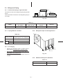
7-5-1. How to Check the PC Board
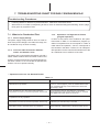
(1) Operating precautions
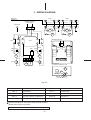
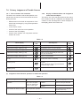
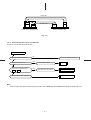
2) The PC board consists of the following 4 parts:
a. Main PC board part:
1) When removing the front panel or the PC
board, be sure to disconnect the power plug
from the AC outlet.
Power relay, indoor fan motor drive circuit and
control circuit, C.P.U. and peripheral circuits,
buzzer drive circuit and buzzer.
2) When removing the PC board, hold the edge
of the PC board and do not apply force to the
parts.
b. Infrared rays receive parts:
Infrared rays receiving circuit
c. Display:
3) When connecting or disconnecting the connectors on the PC board, hold the whole housing. Do not pull at the lead wire.
LED
d. Switch PC board:
Wireless-control, TEMPORARY switch
e. Buzzer PC board:
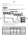
(2) Inspection procedures
1) When a PC board is judged to be failure, check
for disconnection, burning, or discoloration of
the copper foil pattern or this PC board.
Buzzer
f. Transformer PC board:
Transformer
Check the defects of the PC board following the
list below.
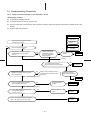
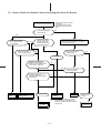
(3) Checking procedure
Table 7-7
Procedure
• Disconnect the power plug from the
AC outlet and remove the PC board
assembly from the electronic parts
base.
Check point (Symptom)
Is the fuse blown?
Trouble cause
• Application of shock voltage
• Short-circuit of the indoor fan
motor
• Remove the flat cable from the
terminal plate.
• Turn the power ON.
Check power supply voltage.
• If the OPERATION lamp flash (0.5
sec. ON, 0.5 sec. OFF), steps 1 – 3
in the right column are not necessary.
1.Between pins 1 and 3 of CN05
(220 – 240V AC)
• Defective power cord, power
switch, fuse or line filter, or wrong
wiring
2.Between pins 1 and 3 of CN06
(12V AC)
• Defective power transformer
3.Between TP6 (+5V) and GND
(5V AC)
• Defective power circuit or shortcircuited load
4.Between TP7 (+12V) and GND
(12V DC)
• Same as above
5.Between TP8 (+12V) and GND
(12V DC)
• Thermal fuse operation
Push the START/STOP button once to
set in operation mode.
(Do not set to the fan only or on-timer
mode.)
Start operation by using the antirestart timer.
Check power supply voltage.
1.Power relay coil voltage (12V DC)
IC02, 9 pin and IC02, 14 pin
• Relay coil cable is broken, relay
driver (IC181) is defective.
2.Between terminals 1 and 2
• Relay contact is defective, SL
connector is defective.
1.All LEDs of the OPERATION lamp,
the TIMER lamp, FAN ONLY lamp,
ECONO. and AUTO lamp light up.
• Display is failure or defect in the
9P housing assembly.
2.After 3 seconds, normal display
does not appear.
– 21 –