1
FINAL ASSEMBLY
CHECKS & ADJUSTMENTS
1) Turn the front wheels completely left then right.
Verify adequate tire, wheel, and brake hose clearance.
Inspect steering and suspension for tightness and proper
operation.
2) Readjust headlamps.
manufacturer’s specifications.
Have vehicle Aligned to
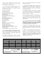
Alignment Specifications
ADJUSTMENT
PREFERRED
RANGE
7°
-0.25°
0.15°
0
±1.0°
±0.63°
±0.15°
±0.15°
Figure 21
Caster
Camber (fixed angle)
Toe-In (each wheel)
Thrust Angle
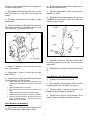
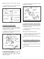
4) Lift the console upward and remove through the
passenger door.
5) Remove the 4 screws attaching the cover boot to
the cover. Slide the boot upward to expose the opening in
the cover and floor pan.
END LINK DISCONNECT PROCEDURE (FOR ROCK
CRAWLING ONLY)
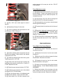
6) Shift the transmission into 2nd and reverse. Verify
a minimum of 1/8” clearance between the shift lever and
floor pan. If necessary, enlarge the opening in the floor pan
with a half round file.
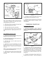
1) Remove the hitch pins and center sections from the
front sway bar end links. Place center sections inside
vehicle for safe storage.
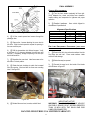
7) Reposition the cover boot. Install one screw on the
left side or 9 o’clock position.
2)
Rotate the sway bar upward.
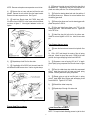
3) Connect the sway bar to the inside of the fender
wells as shown in figure 23.
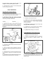
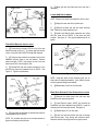
8) Rotate the boot clockwise to match the increased
floor pan opening. Mark and drill the three new mounting
holes. See figure 22.
Figure 23
Figure 22
9)
IMPORTANT NOTICE
WARNING: DO NOT OPERATE THIS VEHICLE
ON PUBLIC ROADS OR AT SPEEDS GREATER
THAN 15 MPH WITH THE SWAY BAR END
LINKS DISCONNECTED.
Reinstall the cover boot, console, and shift boot.
RANCHO INDUSTRIES USA LIMITED WARRANTY
11