1
US 20120074254A1
(19) United States
(12) Patent Application Publication (10) Pub. No.: US 2012/0074254 A1
Delory
(54)
(76)
Mar. 29, 2012
INTEGRATED PORTABLE ELECTRONICS
TESTER
(51)
Publication Classi?cation
Int. Cl.
B65H 75/30
(2006.01)
Inventor:
(52)
us. Cl. ................................................... .. 242/3962
(21) App1.No.:
(22)
(43) Pub. Date:
Filed;
Paul Delm'ys Malden, MA (Us)
13/312,155
(57)
Dec, 6, 2011
A device and method for testing the functionality of various
electronic device components. The device is portable and is
ABSTRACT
capable of being upgraded With changes in technology. The
Related US. Application Data
device is enclosed Within a housing, Which comprises a poWer
supply and a display. The disclosed device incorporates a
(60) Division of application No. 12/080,915, ?led on Apr.
tester for personal computer and laptop components, includ
ing but not limited to, poWer supply, microprocessor, moth
erboard, system memory, video subsystem, mass storage
devices, and cables.
7, 2008, noW Pat. No. 8,095,339, Which is a continua
tion-in-part of application No. 11/513,622, ?led on
Aug. 31, 2006, noW Pat. No. 7,376,537.
154
1150 FL‘ 1,51
153
157
~159
_ —158
1
l
152
153
5154
155
Patent Application Publication
Mar. 29, 2012 Sheet 1 0f 8
US 2012/0074254 A1
FIG.1
Patent Application Publication
Mar. 29, 2012 Sheet 2 0f 8
US 2012/0074254 A1
Patent Application Publication
l
Mar. 29, 2012 Sheet 4 0f 8
NO
YES
PASS
7
NO
Use device to power PC;
Prueeedlo further mu
Pun defective;
Needs replaeemem
I. Dos PC power on? >-_> Test Power Supply
V
US 2012/0074254 A1
Run Motherboard and
2. Does PC POST?
Processor Tests
‘
Device will deploy errors if
componenls are defective
YES
‘
RunRAMTests
Defecli" Pans
need replacing
proceed to rum“: n‘
: ms
‘
l
.
.
.
FAIL
Defective RAM
QM:
will display mots If
componmts are defective
chipl
need
mud"
Proceed to funher netting
PASS
Results of POST tat ‘
battery:
’
No mars found;
P(I dos not POST
I:> I
I
r hcing
3. Does PC have video?
Pos T OK
l
Disconnect hard drive
"0 PCS T
and repeat POST tests
Video card
defective; ,Needs
replacqnent
l 4. Does PC mter BIOS?
Errors found;
PC does not POST
Use device to provide
video output; Proceed to
funhq' tests
BlOS chip needs to
be fhshed or
replaced
Proceed to ?nher resting l
V
All relevant hardware has been tested.
If PC does not load operating system,
problems are so?warerehled.
FIGURE 4
V
.
7
Remove hard drive and connect to
device for H‘DD error checking, virus
and malwarescnns, and data
recovu'y. Replace HDD if fails tats.
Patent Application Publication
Mar. 29, 2012 Sheet 5 0f 8
US 2012/0074254 A1
101
~10?)
104
109
108
1,110
_/105
/112
113"”
111————~
115
'
114\_ '
ii:;
106
:1.
116
m1
117
FIG. 5
Patent Application Publication
Mar. 29, 2012 Sheet 6 0f 8
US 2012/0074254 A1
125“
124-‘
1235
122‘_\
—129
"128
—127
132""
p- 126
139-
~ 130
140 -_
\
133
134
138
137—
_131
Patent Application Publication
Mar. 29, 2012 Sheet 7 0f 8
US 2012/0074254 A1
141
/-r-142
"\
144
FIG. 7
143
Patent Application Publication
Mar. 29, 2012 Sheet 8 0f 8
US 2012/0074254 A1
154
15\0 Ill
1151
153
157
\
153
EH1]
M\_160
5
\
.
~
~159
_ ‘158
\
I
152
153
157
l
~15‘;
161%
ii
{I
i:ll
—158
~159
US 2012/0074254 A1
INTEGRATED PORTABLE ELECTRONICS
TESTER
CROSS REFERENCE TO RELATED
APPLICATION
[0001]
This application is a divisional of prior U.S. appli
cation Ser. No. 12/080,915 ?led on Apr. 7, 2008, Which is a
Mar. 29, 2012
evolve; the softWare con?guration is at least as important to
proper operation as the hardWare. A service technician cannot
be said to have made a complete diagnosis unless he has also
tested a computer’s softWare. (This is particularly true in light
of the current epidemic of viruses and spyWare; at present,
nearly every WindoWs-based machine the service technician
encounters Will be infested With some form of “malWare.”)
continuation-in-part of prior US. application Ser. No.
Additionally, the service technician Will frequently need to
11/513,622 ?led on Aug. 31, 2006, noW abandoned, the con
tents of Which are incorporated herein by reference.
retrieve data stored on a malfunctioning computer, and no
BACKGROUND OF THE INVENTION
[0002] 1. Field of Invention
[0003] The invention relates generally to the ?eld of testing
the condition of a computer or laptop and the components
and/ or peripherals thereof and includes an apparatus and
method for achieving testing.
[0004]
2. Description of the Related Art
[0005] Diagnosis of a faulty computer system can be a
dif?cult process. The computer service technician is charged
With identifying all the faults in a given system in quick and
accurate fashion. Prior to the advent of the instant invention,
the methods a technician may utiliZe to accomplish this task
qualify as unsatisfactory. Presently, one method entails trial
and error, replacing the various components of a PC With
components that are knoWn to Work properly. This constitutes
a cumbersome and time-consuming process that requires the
technician to continually have on hand an inventory of tools
tool presently available makes any provision for such data
retrieval due to the design of present systems.
[0010] A large number of diagnostic tools for individual PC
components are knoWn to the art, and in fact are in Wide use
in the industry. But there exists in the art no portable, univer
sal, completely modular, expandable, and upgradeable device
that integrates into one package all the tools a ?eld service
technician needs, tests each PC component in its native oper
ating environment, replicates the function of faulty PC com
ponents, provides for the testing of a PC’s softWare condition,
and alloWs for the retrieval of data from a malfunctioning PC.
[0011] Furthermore, there are additional challenges When
repairing a laptop PC, over and beyond those described
above, because of the lack of standardiZation in mobile com
puting. Desktop PCs conform to rigid and detailed universal
speci?cations, Which are set by industry groups and therefore
utiliZed industry-Wide. Laptop PCs, hoWever, have far feWer
such standards. Individual manufacturers engineer their oWn
components to their oWn speci?cations, and therefore there is
and knoWn-good parts.
a vast assortment of different components in use in the indus
[0006] Another method is to use a variety of computer
testing tools, Which are knoWn in the art, to test all the various
try. Components vary Wildly betWeen different manufactur
components/peripherals of the PC. Once again, to accomplish
testing and repair in this manner, the technician must have
on-hand a large inventory of tools, each designed to test a
single PC component. Further, the technician must once again
possess an inventory of knoWn-good parts to replicate the
function of components he ?nds to be faulty.
[0007] These methods become even more unsatisfactory
When one considers hoW quickly technology changes. In
order to stay abreast of the frequent and substantial changes in
computing technology, the technician must alWays be pur
chasing neW tools designed to test the functionality of such
neW devices and standards as are developed. Moreover, When
these neW devices and standards are developed, their adoption
is never immediate, meaning that a technician Will alWays be
required to service a mix of old and neW technologies. Thus,
he does not simply discard his oldtools in favor of the neW, but
rather adds the neW tools to the old.
[0008] The result of these practices is a toolbox that is ever
larger, ever more unWieldy, and ever more expensive. Of
higher import, if a technician requires a large number of tools
in his daily business, he must be pro?cient in the use of a large
number of tools. As Well, the technician must understand hoW
to operate each of the tools in his kit, hoW they relate to one
another, and hoW to interpret the various and extensive results
and/ or outputs of the tests. In short, there is a burden placed
upon the technician to coordinate and understand the large
and diverse number of data With Which he is regularly pre
sented.
[0009]
Furthermore, the hardWare diagnostic tools pres
ers, betWeen different models produced by the same manu
facturer, and even betWeen different machines of the same
make and model. The service technician, of course, is charged
With repairing all of these machines, regardless of the differ
ences in components. Therefore, he must have tools capable
of diagnosing and repairing this large and sometimes baf?ing
array of components.
[0012] The Portable Electronic Tester disclosed in US.
patent application Ser. No. 11/513,662 to Delory, and incor
porated herein by reference, While an important step in this
direction, has only limited functionality for laptops. The
desktop unit is designed to Work With industry-standardized
technologies, only those laptop components that are stan
dardiZed can be diagnosed by the desktop unit. While the
apparatus is capable of testing laptop hard drives, and the
continuity of many important cables used in laptops. But it is
incapable of diagnosing laptop poWer supplies, processors,
memory, video output, or video display panels, as these com
ponents, Which are standardized on desktop PCs, have no
equivalent uniformity on laptops. There is a clear need, then,
for a test device that is capable of diagnosing and repairing the
diverse and sundry components it Will encounter in the
mobile computing environment.
[0013] But any solution Will introduce a different problem.
Because of this proliferation of different connector types for
laptop components, the only practicable solutions Will
involve an assortment of adapters designed to interface the
tool With the all the various connector types the tool’s user
Will inevitably encounter in the ?eld. With any collection of
adapters, hoWever, there is alWays the risk that adapters Will
ently available and knoWn in the art make no provision for the
be lost or broken, rendering the tool useless. Therefore, the
testing of a computer’s softWare con?guration. This consti
tutes a glaring Weakness, since as present day computers
breakage of these all-important adapters.
device must also take measures to eliminate the risk of loss or
US 2012/0074254 A1
[0014]
Mar. 29, 2012
Us. Pat. No. 5,991,805, issued to Krukovsky in
nents. While it uses its oWn components to compensate for the
1999, discloses a tester for computer audio and video that is
both portable and universal. But this device, While an obvious
improvement to other testers known in the art, is limited in
scope to the testing of video and audio. In a ?eld service
environment, it Would be just one more tool in the service
missing functionality of faulty components, it runs its oWn
softWare-based test routines, rather than enabling the PC
under test to load into its normal operating environment.
technician’s kit, rather than an integrated diagnostic solution.
[0015] Us. Pat. No. 6,775,192, issued to Harrington et al.
in 2004, discloses a DRDRAM chip tester, Which differs from
memory chip in a reduced poWer state. But this device
functioning PC, using the Martin device.
[0019] Most importantly, hoWever, the Martin device’s
diagnostic method is irreparably obsolete: It simply Would
not function With today’s technology. Many of its diagnostic
subroutines rely upon accessing the Test Manager diagnostic
requires the memory chips to be inserted in the device’s test
program stored in the boot ROMs of the Macintosh comput
banks. In a ?eld service environment, the end user Would be
ers of this device’s era. But Macintosh computers no longer
make use of boot ROMs, and WindoWs-platform PCs never
other DRDRAM testers known to the art in that it can test a
obliged to remove the chips from the computer under test and
place them in the device. This is an obvious inconvenience.
But, far more importantly, this device tests only the memory
chips themselves. In a ?eld service environment, the service
technician requires a memory test that tests the entire memory
subsystem. It is imperative, therefore, that the ?eld service
technician test memory chips in their native operating envi
ronmentia test the Harrington device cannot conduct.
[0016] Us. Pat. No. 4,837,764, issued to Russello in 1989,
discloses “an apparatus and method for testing the condition
Thus, the end user cannot assess the condition of a PC’s
softWare con?guration, nor can he retrieve data from a mal
did. The Martin device Would not function on any PC manu
factured today. Moreover, even When the Macintosh’s boot
ROM system Was state-of-the-ar‘t, this device could make no
claim to universality: The Macintosh never enjoyed much
market support; this device Would function on, at best, one
machine in ten. A computer testing device that cannot test
WindoWs-based PCs isn’t of much practical value.
[0020] In summary, investigation of these disclosed devices
illustrates that presently, there is no single device knoWn in
of computer peripherals.” This device, hoWever, is limited in
scope to the testing of computer peripherals such as printers
the art that meets the requirements of a ?eld service techni
and modems: It makes no provision for the testing of internal
PC components. This device is not portable. This device
makes no provision for upgrading to neW technologiesiand
indeed, the technologies around Which this device is built are
noW obsolete, meaning that this device Would not function
tester Which alloWs the user to check a variety of component
cian as nothing in the prior art discloses a portable integrated
and functionality.
SUMMARY OF THE INVENTION
With any PC peripheral sold today. Furthermore, the Russello
[0021]
device relies upon a series of diagnostic cards, Which cards
need to be Written With diagnostic routines suitable for each
individual peripheral under test. This solution is impracti
cable: To have on hand a diagnostic card appropriate for every
peripheral type knoWn in the art Would be not just unneces
not anticipated, rendered obvious, or even present in any of
the prior art mechanisms, either alone or in any combination
thereof.
sarily cumbersome, but virtually impossible.
laptop diagnostics and repair, Which device integrates into
[0017] Us. Pat. No. 5,357,519, issued to Martin in 1994,
discloses “a device and method for diagnosing a faulty com
puter system Without disassembling the system.”These “non
intrusive diagnostics of a computer system” alloW the end
user to connect the Martin device to the externally accessible
ports of a malfunctioning PC, Whereupon the device Will
execute a series of test routines, and report back to the end
user any errors in the PC’s hardWare it ?nds. Since PCs are
built in many different con?gurations, the device operates via
a series of removable ROM packs and port packs: The user
inserts the appropriate ROM pack, Which contains the appro
priate test routines for the particular PC under test, and the
appropriate port pack, Which replicates the port con?guration
on the particular PC under test. Thus, the Martin device
alloWs an end user With little training to diagnose PC prob
lems accurately, Without ever needing to access the interior of
the PC under test.
[0018] As With the Russello device, the Martin device relies
upon a series of removable ROM packs and port packs,
requiring the end user to have on hand tWo accessory packs
for each computer to be tested; if these packs are not present,
the device cannot function. These packs are cumbersome, and
they call into question the Martin device’s claim to portabil
ity: Although the device itself may be portable, the end user
must also carry a potentially very large number of ROM and
port packs. Furthermore, the Martin device makes no provi
sion for replicating a malfunctioning PC’s faulty compo
The instant invention, as illustrated herein, is clearly
[0022] The primary object of the present invention is to
provide a single, portable device useful for computer and
one package all the tools a ?eld service technician needs in his
daily business.
[0023]
Another object of the present invention is to provide
a diagnostic device that can be upgraded to accommodate
such neW technology as Will inevitably be developed, While
still remaining useful for older and legacy technologies.
[0024] Another object of the present invention is to provide
a diagnostic device that can also replicate the functions of
faulty PC and laptop components, alloWing the PC or laptop
under test to be operated normally, and in its native operating
environment, so that all components can be tested in-environ
ment, and under their normal operating conditions.
[0025] Another object of the present invention is to provide
a device that enables the service technician to test a PC or
laptop’s softWare con?guration, and to retrieve data stored on
a PC, even When that PC cannot do so itself due to some
malfunction.
[0026]
Another object of the present invention is to provide
a method for the diagnosing and repairing of a computer or
laptop that requires no system-speci?c knoWledge on the part
of the end user, and relatively little general repair knoWledge.
[0027] There has thus been outlined, rather broadly, the
more important features of the portable electronics tester in
order that the detailed description thereof that folloWs may be
better understood, and in order that the present contribution to
the art may be better appreciated. There are additional fea
US 2012/0074254 A1
Mar. 29, 2012
tures of the invention that Will be described hereinafter and
The apparatus is universal, portable, completely modular,
Which Will form the subject matter of the claims appended
hereto.
[0028] In this respect, before explaining at least one
embodiment of the invention in detail, it is to be understood
that the invention is not limited in its application to the details
of construction and to the arrangements of the components set
forth in the following description or illustrated in the draW
ings. The invention is capable of other embodiments and of
being practiced and carried out in various Ways. Also, it is to
be understood that the phraseology and terminology
employed herein are for the purpose of description and should
not be regarded as limiting.
expandable, and upgradeable for neW technology.
[0029] These together With other objects of the invention,
along With the various features of novelty, Which characteriZe
the invention, are pointed out With particularity in the claims
annexed to and forming a part of this disclosure. For a better
understanding of the invention, its operating advantages and
the speci?c objects attained by its uses, reference should be
made to the accompanying draWings and descriptive matter in
Which there are illustrated preferred embodiments of the
invention.
BRIEF DESCRIPTION OF THE SEVERAL
VIEWS OF THE DRAWINGS
[0030] FIG. 1 is an isometric vieW of the instant invention,
illustrating an overvieW of the location of the Main Control
Panel and the Four Removable Modules;
[0031] FIG. 2 is an isometric vieW of the instant invention,
further illustrating the components of the Main Control Panel
and the Four Removable Modules;
[0032] FIG. 3 is an isometric vieW of the instant invention,
further illustrating the PC’s PCI bus; inputs for a standard
ATX/BTX Molex connector; the third DC poWer output With
a standard ATX/BTX peripheral poWer output connector;
preferably featuring a retractable cable; and, a fourth DC
poWer output With a SATA peripheral poWer connector; pref
erably featuring a retractable cable.
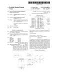
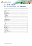
[0033] FIG. 4 is a How chart of the method.
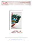
[0034] FIG. 5 is an isometric vieW of the instant invention,
further illustrating a video test module for testing a laptop
computer’s video system.
[0035] FIG. 6 is an isometric vieW of the instant invention,
further illustrating a poWer supply module for testing a laptop
computer’s poWer supply.
[0036] FIG. 7 is an isometric vieW of the instant invention,
further illustrating a POST/RAM test module for testing a
laptop computer’s POST process and RAM.
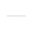
[0037] FIG. 8 is an isometric vieW of the instant invention,
further illustrating a selector Wheel for use in conjunction
With the instant invention.
DETAILED DESCRIPTION OF THE INVENTION
[0038]
The instant invention, Which, in its integrated form
may be deemed the “TechMate,” comprises an apparatus and
methods for (1) testing the condition of computer compo
nents and/or peripherals; (2) diagnosing speci?c problems
With those components and/or peripherals; (3) providing
electrical poWer to computers that cannot poWer themselves
due to some malfunction; (4) replicating the function of mal
functioning PC components, so that testing can proceed
unhindered; and (5) retrieving user data from computers
When they cannot do so themselves due to some malfunction.
[0039] The instant invention may be contained in a separate
housing or integrated into the same chassis With a laptop
computer. HoWever the device is accommodated, it Will con
sist of a main control panel controlling and coordinating a
series of modules designed to test all the relevant functions of
a PC’s components and peripherals.
[0040]
Taking into account the present state of the art, the
current embodiment of the TechMate Will feature four remov
able modules 39-42, as shoWn in FIGS. 1-3. These respective
modules include a module for testing a malfunctioning per
sonal computer’s poWer supply 40; a module for personal
computer’s mass storage devices 41; a module for testing a
personal computer’s cable continuity 42; and a module for
testing a personal computer’s 39 POST, RAM, and video.
Again, this is only the current embodiment, since as technol
ogy changes these modules can be replaced With modules
designed to test Whatever neW technology is developed. There
can even be more or feWer modules depending upon the needs
of the technology.
[0041] The TechMate Main Control Panel 38 is the main
user interface for the device, and controls and coordinates the
individual test modules. It consists of a master poWer sWitch
3; a means of communicating With the end user, preferably an
LCD screen 4; a means of receiving user input and com
mands, preferably a series of cursor controls 5; a micropro
cessor; and one or more nonvolatile memory means for stor
ing commands and operating instructions.
[0042]
The PoWer Supply Test Module 39 is designed to
provide complete testing of a PC’s poWer supply, as Well as to
provide poWer to a PC Whose poWer supply has malfunc
tioned. It Will consist of a DC poWer supply comprising a
recti?er and AC to DC converter, Which supply is capable of
producing electrical poWer su?icient to enable not only the
module’s oWn operation, but to provide poWer to a malfunc
tioning PC; a simple ATX/BTX poWer supply tester With
inputs for both a standard ATX/BTX Molex connector 9 and
a Pentium IV auxiliary poWer connector 7; a panel of LEDs to
indicate a poWer supply’s condition 6; a ?rst DC poWer output
With a standard ATX/BTX Molex connector, preferably fea
turing a retractable cable 8; a second DC poWer output With a
Pentium IV auxiliary poWer connector, preferably featuring a
retractable cable 10; a third DC poWer output With a standard
ATX/BTX peripheral poWer output connector, preferably
featuring a retractable cable 12; and a fourth DC poWer output
With a SATA peripheral poWer connector, preferably featur
ing a retractable cable 11.
[0043] Of course, it Will be obvious to one skilled in the art
that this module can be redesigned in future to accommodate
changes in poWer supply technology and thus, as the ATX
style connectors that are the current state of the art become
obsolete and are replaced With neWer standards, neW modules
can be easily designed that Will alloW the device to test and
poWer devices built to those neWer standards.
[0044] When the technician engages a PC that cannot
poWer on, the end user Will begin his diagnostic procedure by
testing the PC’s poWer supply. He Will connect the poWer
supply’s Molex connector to the ATX/BTX Molex PoWer
Connector Test Input Port 9. If the PC to be tested has a
Pentium IV processor, he Will also connect the poWer sup
ply’s auxiliary poWer connector to the Pentium IV Auxiliary
PoWer Connector Test Input Port 7; otherWise, this port Will
not be used. The condition of the poWer supply Will be indi
US 2012/0074254 A1
Mar. 29, 2012
cated on the Power Supply Tester Indicator LEDs 6 as fol
non-technical language. Third, the module’s microprocessor
loWs: if all of these LEDs light up, the power supply functions
Will load the video test subroutines from the module’s non
volatile memory means, and execute the video tests. These
video tests Will display a test pattern on the PC’s monitor. The
device Will display on the LCD screen 4 a question asking the
to speci?cations; if one or more fail to light, the poWer supply
is defective and needs replacement.
[0045] If, by means of this test, the end user determines that
the poWer supply is defective, he can then use the device as a
surrogate poWer supply, in order to poWer the PC for further
testing. To achieve this, the user unspools the ATX/BTX
Molex PoWer Output 8 and connects it to the PC’s mother
board. If the PC has a Pentium IV processor, he also unspools
and connects the Pentium IV Auxiliary PoWer Output 10;
otherWise, this cable is not used.
[0046] The technician can noW poWer the PC normally. To
boot the PC, of course, the technician Will need to provide
poWer to its hard drive and Will do so by unspooling and
connecting to the PC’s hard drive either the ATX/BTX Stan
dard Peripheral PoWer Output 12, or the SATA Peripheral
PoWer Output 11, depending on Which poWer connector the
component to be tested uses.
end user Whether the test pattern displayed properly, and Will
receive the user’s input via the device’s control panel 5.
[0050] Because this module has its oWn microprocessor,
volatile memory, and video display subsystem, it has the
ability to surrogate any of the above components, if testing
should prove them faulty. If the PC’s processor is faulty, this
module’s microprocessor Will take over, so that the remaining
tWo tests can be run. Similarly, if the PC’s system memory
should prove faulty, this module Will alloW the PC’s processor
to load the data it needs into the module’s oWn volatile
memory means, so that the other tests can proceed. Addition
ally, this module features an SVGA Video Output Port 2 that
can be used When a PC’s video card is faulty. When an end
user cannot see the test pattern that should be displayed on the
[0047] The POST/RAM/Video Diagnostics Module 39 is
designed to provide complete testing of a PC’s PoWer-On
Self-Test (POST) process, processor, motherboard, system
memory, and video subsystem; and also to provide surrogate
test PC’s monitor as part of the video subsystem test (as
described above), he simply connects the PC’s monitor to the
SVGA Video Output Port 2. The test pattern Will then be
system memory, a surrogate video card, or even a surrogate
processor, as needed. It consists of a microprocessor; one or
more nonvolatile memory means used to store the test sub
routines and a database of error codes and resolutions; a
knoWs the PC’s monitor is Working normally, and that its
video card is defective and needs replacement; if the test
means of communicating With the device’s companion per
sonal computer (“PC”), preferably a USB or Ethernet inter
face, to load neW or updated test routines and/or POST error
displayed again. If the end user can noW see the test pattern, he
pattern does not display, the end user knoWs this monitor is
defective.
[0051]
The Mass Storage Testing Module 41 is designed
alloW the user to connect a mass storage device (usually a hard
disk drive) to the device in order to (1) test its condition and
functionality, (2) identify any errors or problems that may be
codes into its nonvolatile memory 36; a volatile memory
means to be used in the event of faulty volatile memory in the
present in the softWare stored on the mass storage device
PC under test; a POST/RAM/Video diagnostics cable,
designed to ?t into a standard PCI expansion slot and to
being tested, and (3) make it usable on a functioning PC, so
that any data stored on the mass storage device being tested
function on the PC’s PCI bus 1; and a standard SVGA video
can be retrieved. It consists of a microprocessor; a nonvolatile
memory means used to store commands and instructions for
the microprocessor; a volatile memory means to be used as a
output port used for this module’s video test subroutines 2.
Here, too, it Will be obvious to one skilled in the art that this
module can be easily redesigned in future to accommodate
changes in technology. Indeed, the module Will receive
data buffer; a series of input ports to Which a mass storage
device can be connected in order to make it visible and read
updated POST error and resolution information via its com
munication means 36 as often as needed, and When the PCI
standard bus that is the current state of the art becomes obso
able to the device’s companion PC, namely an IDE standard
lete, this module can be easily redesigned With such neW
technology as Will be developed.
ports Which can be used either as secondary inputs, or as
desktop input port 13, an IDE standard notebook input port
18, and a SATA standard input port 15; a series of input/output
Cable 1 from the module and connect it to any available PCI
destination output ports for the devices connected to the input
ports as described above, namely an IDE standard desktop
input/output port 19, an IDE standard notebook input/ output
port 14, and a SATA standard input/output port 17; and a
mode selector sWitch that controls the function of the input/
slot on the motherboard. First, the module’s microprocessor
output ports 16.
Will execute the POST test subroutines stored in the nonvola
tile memory means, and conduct the POST test. If there are
errors detected in the POST, it Will record the POST error
[0052] Again, it Will be obvious to a person skilled in the art
that this module can be redesigned to accommodate changes
in technology: As the IDE and SATA standards become obso
lete and are replaced by neW standards, this module can be
easily replaced With neW modules designed to test and read
[0048] When the end user encounters a PC that (1) does not
POST, or (2) does not poWer on even though the poWer supply
tests normal, he Will unspool the POST/RAM Diagnostics
code(s) that Were returned, and reference them against the
database of POST error codes and resolutions stored in its
nonvolatile memory means.
from such neW mass storage technologies as shall be devel
[0049]
oped.
It Will then display any POST error codes for the
user, on the device’s LCD screen 4. It Will also list there, in
[0053]
non-technical language, the remedy for the POST error codes
draWn from the database of resolutions stored in its nonvola
tile memory means. Second, the module’s microprocessor
Will load the memory test subroutines stored in the module’s
nonvolatile memory means, and test the system’s memory. If
there are any problems detected With the system’s RAM, it
Will display those errors on the LCD screen 4, again in clear,
RAM tests outlined above, the technician still needs to test the
After he has conducted the poWer supply and POST/
PC’s mass storage devices, in particular its hard drive, and he
may Wish to retrieve data stored thereon. To do this, he Will
connect the hard drive to the device. If the drive in question is
an IDE-type drive from a desktop PC, he Will connect it to the
device using either the IDE Standard Desktop Input Port 13,
or the IDE Standard Desktop Input/Output Port 19, and Will
US 2012/0074254 A1
power it using the ATX/BTX Standard Peripheral Power Out
put 12 from the Power Supply Test Module. If the drive in
question is an IDE-type drive from a notebook PC, he Will
connect it to the device using either the IDE Standard Note
book Input Port 18, or the IDE Standard Notebook Input/
Output Port 14, and Will again poWer it using the ATX/BTX
Standard Peripheral PoWer Output 12 from the PoWer Supply
Test Module.
[0054] If the hard drive in question is a SATA-type hard
drive (for either a notebook or desktop PC), he Will connect it
to the device using either the SATA Standard Input Port 15 or
the SATA Standard Input/Output Port 17, and poWer it using
the SATA Peripheral PoWer Output 11 from the PoWer Supply
Test Module. Regardless of hoW the drive to be tested is
connected, the module Will then transmit connection data to
the device’s companion PC via the module’s PC Data Link
Port 36. The mass storage device being tested Will appear
normally on the companion PC, Where it can be tested, or its
data copied.
Mar. 29, 2012
[0066]
The TechMate incorporates all the hardWare diag
nostic tools a ?eld service technician needs in one portable
device approximately the siZe of a paperback book. The
device interfaces With any standard WindoWs laptop through
a USB port and can even be incorporated into the same chassis
With a laptop PC. It includes a poWer supply tester; PCI
bus-based testing for motherboards, processors, system
memory, and the POST process; and cable continuity check
ers. More importantly, it includes a surrogate poWer supply
and a surrogate video card, so that the technician in the ?eld
can still poWer up a PC With a malfunctioning poWer supply,
or can still get video output from a PC With a malfunctioning
video card.
[0067] This enables the technician to proceed to further
testing, even When these devices do not Work. It alloWs him to
test all the relevant hardWare of a PC, even When some of that
hardWare is malfunctioning. Most importantly of all, hoW
ever, the TechMate provides connectivity for hard disk drives.
This module can also be used to clone a hard disk
This alloWs the ?eld service technician to interface a malfunc
tioning PC’s hard disk With his laptop; once there, he can test
drive. The Mass Storage Test Module Mode Selector SWitch
1 6 controls the function of the three mass storage input/ output
the drive, scan for any softWare errors, scan for viruses and
spyWare, and retrieve any data his client may need.
ports 14, 17, and 19. When this sWitch is in “Copy” mode,
these ports function as inputs; When in “Clone” mode, they
capacity to fully test and run diagnostics on a personal com
[0055]
function as outputs. To clone a hard disk completely, the
technician need only set the module to “Clone” mode and
attach it to one of the module’s input-only ports 13, 15, or 18.
The data Will then be copied onto a device attached to any one
[0068]
In addition to the instant invention possessing the
puter, additional modules have been incorporated to alloW for
equivalent and substantive testing of a laptop’s primary sys
tems including poWer, video and POST/RAM as illustrated
and described beloW.
of the output ports. During the cloning process, the LCD
[0069]
screen 3 Will display the task progress, along With any errors
that may arise.
the art, the current embodiment of the device Will feature four
removable modules 39-42, as shoWn in FIGS. 1-3. These
respective modules include a module for testing a malfunc
[0056]
The Cable Continuity Testing Module 42 is
designed to test the continuity of a variety of cables com
monly used in PCs. It consists of a loW-capacity poWer
Furthermore, taking into account the present state of
tioning personal computer’s poWer supply 40; a module for
source, preferably either a capacitor charged from the
personal computer’s mass storage devices 41; a module for
testing a personal computer’s cable continuity 42; and a mod
device’s main poWer supply or a standard commercial battery
ule for testing a personal computer’s 39 POST, RAM, and
such as a AA; a means of communicating to the end user the
video. To this original embodiment Will noW be added three
additional removable modules 101, 119, and 141, as shoWn in
FIGS. 5-8. These modules include a module for testing a
results of the continuity testing, preferably a small, simple
electro-active speaker that Will sound an audible signal When
a circuit is completed in a functioning cable; and a series of
test ports to Which the cables Will be connected, as are
described beloW.
[0057] To test any cable, the end user need only connect
each end of the cable to each test port. It makes no difference
Which end of the cable is plugged into Which test port. If the
cable is sound, and functioning to speci?cations, the audible
buZZer Will sound; if the cable is faulty, it Will not. The module
can test the folloWing cables:
[0058]
21;
l. RJ-ll (standard phone line), by connecting 20 to
laptop computer’s poWer supply 119; a module for testing a
laptop computer’s video system 101; and a module for testing
a laptop computer’s POST process and RAM 141. Again,
only the preferred embodiment is described herein, since as
technology changes these modules can be replaced With mod
ules designed to test Whatever neW technology is developed.
Therefore, those skilled in the art may utiliZe greater or feWer
modules than present disclosed depending upon the needs of
the technology at the time of operation of the instant inven
tion.
[0070] FIG. 5 illustrates the Laptop Video Test Module 101
is designed to alloW complete testing of a laptop computer’s
[0059] 2. RJ-45 (standard Ethernet patch cable), by con
necting 24 to 25;
[0060] 3. USB Type-A to USB Type-B, by connecting 22 or
video display, and inverter board (if any); and to surrogate the
30 to 26;
function of any element of the video system, should any prove
[0061] 4. USB Type-B to USB Type-B (USB extension), by
faulty. It Will consist of a microprocessor; one or more video
connecting 22 to 30;
[0062] 5. IDE Standard Desktop, by connecting 23 to 26;
[0063] 6. IEEE-l394, by connecting 28 to 29;
[0064] 7. SATA, by connecting 31 to 32;
[0065] 8. SVGA, by connecting 33 to 34.
Once more, it Will be obvious to one skilled in the art that this
module can be easily adapted to test any combination of
cables.
video subsystem, including its video controller, integrated
logic controllers suitable to drive any of the various displays
in common use in the art; one or more nonvolatile memory
means used to store commands and instructions for the micro
processor and video logic controller(s); a video output
capable of sending video test patterns to a video display under
test, featuring a retractable cable terminating in a receiver
designed to accommodate an adapter; a series of adapters
suitable to interface the receiver terminating the video output
cable With any connector type in common use in the art 108,
US 2012/0074254 A1
and 110-112, Which adapters are arranged on a selector Wheel
105 described more particularly below; a standard SVGA
video connector for the video output 103; a standard DVI
video connector for the video output 102; a selector sWitch
113 controlling the destination of the video being output, and
capable of directing the output to the SVGA video connector,
the DVI video connector, or the assortment of laptop video
Mar. 29, 2012
[0073] Of course, it Will be obvious to one skilled in the art
that this module can be redesigned in future to accommodate
changes in poWer supply technology and thus, as the connec
tors that are the current state of the art become obsolete and
are replaced With neWer standards, neW modules can be easily
designed that Will alloW the device to test and poWer devices
built to those neWer standards.
interface adapters; a video input capable of receiving video
[0074]
from any laptop video controller then in common use in the
art, featuring a retractable cable terminating in a receiver
designed to accommodate an adapter; a series of adapters
poWer on, he Will begin his diagnostic procedure by testing
suitable to interface the receiver terminating the video input
cable With any connector type then in common use in the art
114-118, Which adapters are arranged on a selector Wheel
107, as described more particularly beloW.
[0071] When a technician encounters a laptop PC that does
not display video, he must ?rst determine Whether the laptop
is delivering video to its integrated video display, and then
Whether the video display is displaying it properly, since the
problem could lie With either or both of these components. To
do this, he Will ?rst disconnect the laptop’s integrated video
display from its video controller on the laptop’s motherboard,
select the appropriate adapter on the tool, and then connect
the laptop’s display to the tool. The tool Will send a video test
pattern to the laptop’s display. If the video test pattern dis
plays properly, the technician knoWs the display is function
ing; if it does not, the technician knoWs the display is faulty
and needs to be replaced. Next, the technician Will test the
laptop’s video card and video output system. To do this, he
Will select the appropriate adapter from the adapter Wheel,
and connect the laptop’s video controller to the device. The
video controller’s normal output can then be displayed on a
standard PC video monitor connected either the standard
SVGA video output 103 or the standard DVI video output
102. Alternatively, if a knoWn-good reference monitor is not
available at the time of testing, the apparatus Will verify that
raW data is being passed from the video controller, and dis
play con?rmation on its internal LCD display.
[0072] FIG. 6 illustrates The PoWer Supply Test Module
119 is designed to provide complete testing of a laptop PC’s
poWer supply, as Well as to provide poWer to a laptop PC
Whose poWer supply has malfunctioned. It Will consist of a
DC poWer supply comprising a recti?er and AC to DC con
verter, Which supply is capable of producing electrical poWer
suf?cient to enable not only the module’s oWn operation, but
to provide poWer to a malfunctioning laptop PC; an autorang
ing sensor that alloWs the module to supply the speci?c
requested poWer for an individual unit under test, on demand;
an LCD screen on Which the condition of a poWer supply
under test can be indicated 121; a microprocessor suitable for
controlling the LCD screen; one or more nonvolatile memory
means suitable for storing commands and operating instruc
tions for the microprocessor and LCD screen subsystem; a
series of inputs for the poWer supply tester suitable to inter
When a technician engages a laptop PC that does not
the PC’s poWer supply. He Will connect the laptop’s poWer
supply to the appropriate connector on the series of poWer
supply inputs 122-129. The PoWer Supply Test Module Will
then attempt to draW poWer from the supply under test, and
Will measure its output. The output Will be displayed on the
LCD screen 121, measured in voltage and amperage. The
technician Will then compare the actual output of the poWer
supply under test With the optimal outputithis information
can be found, by FCC rules, printed on the poWer supply itself
(or in the service manual, should the printed badge be missing
or illegible). If the poWer supply proves defective, the tech
nician Will then use the PoWer Supply Test Module to poWer
the laptop for further testing. To do so, he Will select the
appropriate adapter from the DC output connector selection
Wheel 131, using this adapter to connect the DC poWer output
to the laptop under test. The PoWer Supply Test Module,
being designed to deliver the required poWer for any device on
demand, Will then poWer the laptop according to its speci?
cations, alloWing the technician to proceed to further testing.
[0075] FIG. 7 illustrates a The POST/RAM Diagnostics
Module 141 is designed to provide complete testing of a PC’s
PoWer-On Self-Test (POST) process, processor, mother
board, and system memory; and also to provide surrogate
system memory, or even a surrogate processor, as needed. It
consists of a microprocessor; one or more nonvolatile
memory means used to store the test subroutines and a data
base of error codes and resolutions; a means of communicat
ing With the device’s companion personal computer (“PC”),
preferably a USB or Ethernet interface, to load neW or
updated test routines and/or POST error codes into its non
volatile memory; a volatile memory means to be used in the
event of faulty volatile memory in the PC under test; a POST/
RAM Diagnostics Cable, designed to ?t into a standard Por
table Computer Memory Card lnterfaceAdapter (“PCMClA”
or “PC Card”) expansion slot and to function on the PC’s
PCMClA bus 143.
[0076] Here, too, it Will be obvious to one skilled in the art
that this module can be easily redesigned in future to accom
modate changes in technology. Indeed, the module Will
receive updated POST error and resolution information via its
communication means as often as needed, and When the
PCMCIA standard bus that is the current state of the art
becomes obsolete, this module can be easily redesigned With
such neW technology as Will inevitably be developed.
[0077] When the end user encounters a laptop PC that (1)
does not POST, or (2) does not poWer on even though the
face any poWer supply connector type in common use in the
art 122-129; a ?rst DC poWer output With a universal connec
poWer supply tests normal, he Will unspool the POST/RAM
tor; a series of adapters for the ?rst DC poWer output’s uni
versal connector, suitable to interface the DC output With any
available PCMClA slot. First, the module’s microprocessor
poWer supply connector in common use in the art 132-139; a
second DC poWer output With a SATA peripheral poWer con
nector, preferably featuring a retractable cable; and a selector
Wheel for the adapters for use With the ?rst DC poWer output
131, described more particularly beloW.
Diagnostics Cable 143 from the module and connect it to any
Will execute the POST test subroutines stored in the nonvola
tile memory means, and conduct the POST test. If there are
errors detected in the POST, it Will record the POST error
code(s) that Were returned, and reference them against the
database of POST error codes and resolutions stored in its
nonvolatile memory means.
US 2012/0074254 A1
[0078]
It Will then display any POST error codes for the
user, on the device’s LCD screen 4. It Will also list there, in
non-technical language, the remedy for the POST error codes
draWn from the database of resolutions stored in its nonvola
tile memory means. Second, the module’s microprocessor
Will load the memory test subroutines stored in the module’s
nonvolatile memory means, and test the system’s memory. If
there are any problems detected With the system’s RAM, it
Will display those errors on the LCD screen 4, again in clear,
non-technical language.
Mar. 29, 2012
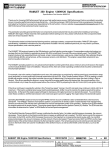
[0083] Positioned over the universal receiver, ?ush With the
top edge of the housing, is a selector Wheel 155 that rotates
around a central axis and uses a spring 156 to alloW it limited
vertical motion. A series of adapters 157-161 is arranged
along this selector Wheel. Each adapter features on one end a
male connector designed to ?t into the female universal
receiver 153, and on the other end a connector suitable to
interface With Whatever device it Will be used to test. The
adapter is oriented such that the end designed to interface With
the universal receiver faces the receiver. This end of the
adapter sits ?ush With the ?oor of the selector Wheel, and is
designed to seal the gap in the selector Wheel such that no dust
[0079] Because this module has its oWn microprocessor,
volatile memory, and video display subsystem, it has the
ability to surrogate any of the above components, if testing
should prove them faulty. If the PC’s processor is faulty, this
module’s microprocessor Will take over, so that the remaining
that the desired adapter is positioned above the universal
receiverithe ready position. The operator then presses doWn
tWo tests can be run. Similarly, if the PC’s system memory
on the selector Wheel, Which loWers the selector Wheel verti
or debris can pass beyond it. The selector Wheel is rotated so
should prove faulty, this module Will alloW the PC’s processor
cally, causing the adapter in the ready position to engage With
to load the data it needs into the module’s oWn volatile
memory means, so that the other tests can proceed.
the universal receiver. The operator then grasps the adapter
and pulls upWard, causing the retracted cable to extend
through the gap in the selector Wheel, unspooling as it pays
[0080]
On each module, all adapters necessary to interface
the universal connector With any of the myriad connector
out.
types it Will encounter are arranged on a selector Wheel. This
[0084] Finally, a key feature of the TechMate is its ability to
receive upgrades. All of the tools the TechMate incorporates
Wheel is designed to alloW them to be stored safely Within the
device, so that they Will not be lost or damaged in transit.
[0081] FIG. 8 displays in its retracted position, a retractable
cable 152 spools completely into the module housing. This
cable terminates in a universal receiver 153, Which, When the
cable is in its retracted position, Will face up toWard the top of
the housing. The spool around Which the cable is Wound 150
features a one-Way locking gear 151 that permits the cable to
extend While preventing it from retracting. A release posi
tioned on the top of the module 154 disengages the one-Way
locking gear, When necessary, to permit the cable to retract.
The universal receiver is recessed into the housing.
[0082] The universal receiver 153 is a female connector 162
designed to accept a male retaining post. This post enters the
female connector, and is held in place by a tongue 163 made
of suitable material, preferably steel. The tongue is designed
to lock the receiver and an adapter together With suf?cient
strength to permit the operator to extend the retractable cable
by gripping the adapter. To that end, the tongue Will permit
only doWnWard motion of the type that engages the adapter
With the receiver, and resists upWard motion of the type that
disengages adapter and receiver. A release 164 serves to dis
engage the tongue and permit the separation of receiver and
adapter, When necessary.
are readily adaptable to any neW technology that Will arise
since each connection originates from a removable plate on
the device. Although individual tools to test the various com
ponents exist, no tool available today has been successful in
integrating these vast functions into one device.
I claim:
1. An apparatus for the management, storage, and use of a
series of adapters, comprising:
a retractable cable;
a spool on Which said retractable cable can be Wound;
a one-Way locking gear for said spool;
a universal receiver terminating said retractable cable;
a selector Wheel for adapters;
a spring permitting limited vertical motion of said selector
Wheel;
a metal tongue for said universal receiver permitting only
engaging motion;
a release for said metal tongue; and
a release for said retractable cable.
*
*
*
*
*