1
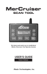
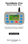
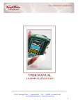
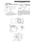
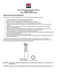
TechMate Pro
TM
Marine Scan Tool
The fastest and easiest way to troubleshoot
Marine Electronic Fuel Injection Systems.
Outboard Supplement
Rinda Technologies, Inc.
www.rinda.com
.
TechMate Pro
TM
Marine Scan Tool
OUTBOARD
ENGINE
SUPPLEMENT
Revision 2
Rinda Technologies, Inc.
4563 N. Elston Ave. • Chicago, IL 60630
www.rinda.com
Tel: (773) 736-6633
Fax: (773) -736-2950
Copyright © 2015 Rinda Technologies, Inc.
Page 3
Limited Warranty
To the original purchaser only, Rinda Technologies, Inc. warrants the supplied
scan tool hardware to be free from defects in materials and workmanship under
normal use for a period of 1 year from date of purchase as evidenced by a copy of
the sales receipt. Rinda Technologies, Inc. makes no other express warranties on
the hardware products. The purchaser’s sole remedy in the event of a breach of
warranty is expressly limited to repair of the defective scan tool hardware. Repair
parts and replacement hardware products will be provided on an exchange basis
and will be either reconditioned or new. All replaced parts become property of
Rinda Technologies, Inc. This limited warranty does not cover damage to the
products resulting from misuse, accident, disaster, abuse, negligence, improper
maintenance, or modification and/or repair of the hardware product other than
by Rinda Technologies, Inc.
The software components in the scan tool are believed to be accurate. Rinda
Technologies, Inc. does not warrant that the operation of the software will be
uninterrupted or error free. Further, Rinda Technologies,Inc. does not warrant or
guarantee the use of, or the results of the use of, the software in terms of correctness, accuracy, reliability, currentness, or otherwise.
Limitation of Liability
Neither Rinda Technologies, Inc. nor its authorized dealer shall be liable for any
defect, indirect, incidental, special, or consequential damages, whether in an
action in contract or tort (including negligence and strict liability), such as, but
not limited to, loss of anticipated profits or benefits resulting from the use of this
scan tool and its software or any breach of any warranty, even if Rinda Technologies or its authorized dealer has been advised of the possibility of such damages.
In no event will Rinda Technologies, Inc. or its authorized dealer’s liability exceed
the price paid for the product.
The information presented in this manual is believed to be accurate. Responsibility for errors, omission of information, or consequences resulting from the use of
this information cannot be assumed by Rinda Technologies, Inc. Rinda Technologies, Inc. retains all rights to make changes to specifications at any time without
notice.
Reproduction of this manual, in whole or in part, is forbidden without the express written permission
of Rinda Technologies Inc.
Manual contents including photographs Copyright ©) 2015 Rinda Technologies Inc. All rights
reserved worldwide.
Mercury and SmartCraft are registered trademarks of Brunswick Corp. All other trademarks are
properties of their respective holders.
Page 4
Table of Contents
Safety Precautions ............................................................. 6
Overview ............................................................................. 7
Engine / EFI System Support:
Smartcraft PCM / ECM systems .................................... 8
Smartcraft ECM-70 systems .......................................... 23
1997 - 2000 DFI ECM .................................................... 26
Mercury #824003 Fuel ECM .......................................... 34
3.0L Carbureted Ignition ECM ....................................... 36
3.0L EFI Fuel ECM ........................................................ 39
2.5L Hi-Perf Racing ECM ............................................... 41
1998 - 2005 2 & 3 Cylinder Carb 4-Cycle ECM ............. 43
2006 - Up 25 / 30hp EFI 4-Cycle ECM .......................... 45
2005 - Up 75 / 90hp EFI 4-Cycle ECM .......................... 47
2001 - 2006 115hp EFI 4-Cycle ECM ............................ 50
Adapters and Accessories................................................. 53
Page 5
Safety Precautions
Before attempting to use the TechMate scan tool please
read and observe the following safety precautions:
• Always refer to and follow the engine and boat manufacturer’s safety and service procedures to prevent personal injury and equipment damage.
• Never connect or disconnect the scan tool with the vehicle’s ignition turned
ON or while the engine is running.
• Always stay clear of any moving or movable engine components when
connecting and using the scan tool.
• When working near marine batteries never use any device that is capable of
producing a spark, high temperature or open flame.
• Marine batteries contain sulfuric acid and produce highly explosive gases
that may ignite. To prevent serious injury always observe this precaution
along with the safety precautions provided by the engine, boat and battery
manufacturers.
• Always test and service a running engine in a well ventilated area.
• Always wear approved eye protection.
IMPORTANT
• The scan tool is a sensitive electronic instrument. Always handle the tool
with care.
• DO NOT subject the scan tool to excessive water spray or expose it to rain.
The scan tool is water resistant but not water proof.
• DO NOT leave the scan tool in direct sunlight for extended periods of time
or subject it to extreme temperatures (hot or cold).
• Store the scan tool in its protective carrying case when not in use. If you do
not have a carrying case, store the scanner in its original packaging.
Page 6
Overview
About this supplemental publication
This publication is intended as a supplement to the main scan tool User Guide.
Please refer to the TechMate Pro User Guide (Figure 1) that was supplied with
your tool for important fundamental information on features and operation.
Figure 1 TechMate Pro User Guide
Outboard System Support
The TechMate Pro scan tool supports a variety of Mercury outboard electronic
engine control systems. Following is a general summary of supported system
types. For specific details, please refer to the appropriate section of this manual
based upon the type of engine control module (ECM) you are working with.
Outboard control systems supported:
•
Mercury PCM-555 / ECM-555 (Smartcraft) ECMs
•
Mercury ECM-70 (Smartcraft) ECMs
•
Mercury 1997-2000 DFI ECMs
•
Mercury #824003 Fuel ECM
•
Mercury 3.0L Ignition ECM
•
Mercury 3.0L Fuel ECM
•
Mercury Racing 2.5L hi-perf (FMS ECM)
•
Mercury 25, 30, 40, 50, 60 HP 4-strokes (24 pin Motorola ECM)
•
Mercury 25 / 30 HP EFI 4-strokes (with Tohatsu powerheads)
•
Mercury 75 / 90 / 115 HP EFI 4-strokes (with Yamaha powerheads)
Page 7
SmartCraft PCM
Figure 2 Mercury PCM-555 & ECM-555
This section describes TechMate Pro scan tool functions related to outboard
engines equipped with Mercury PCM-555 / ECM-555 SmartCraft compatible
EFI modules. This system type was introduced on a variety of Mercury outboard
engines beginning in 2001. We will use the term “PCM” to refer to both styles of
EFI modules.
IMPORTANT NOTE
In 2010 Mercury introduced a new ECM-70 Smartcraft compatible EFI module
as shown in Figure 3. If you are working on an engine that is equipped with a
ECM-70 EFI module please refer to the Smartcraft ECM-70 section in this
manual for diagnostic adapter requirements and details on connecting the scan
tool to the engine.
Figure 3 Mercury ECM-70
Page 8
Smartcraft PCM
Connecting to the PCM-555 / ECM-555 EFI Systems
The TechMate Pro scan tool provides an extensive set of diagnostic and support
functions for troubleshooting engines equipped with the PCM SmartCraft engine
control system.
Two types of diagnostic connectors were used on outboard engines equipped
with these EFI systems. As a general rule most outboard engines 2005 and earlier that utilize Smartcraft PCMs (PCM-555 or ECM-555) are fitted with a 2-pin
diagnostic connector. Starting in 2006 Mercury began using a 4-pin diagnostic
connector on most of their Smartcraft PCM equipped engines. One exception
to this is on Verado engines. All Verado engines 2005 and newer use the 4-pin
style connector.
To connect the TechMate Pro scan tool follow the steps below. The two possible
types of diagnostic adapters required for these systems are shown at the bottom
of this page.
1) Locate the engine’s 4 pin (or 2 pin on some models) diagnostic connector
(DLC). The exact location of this connector is specified in the engine manufacturer’s service manual and may vary depending upon the engine type.
2) With the engine’s ignition switch in the OFF position, plug the scan tool’s
communication cable into the DLC connector. Adapter #94006 is required
for 4-pin applications, adapter #94028 is required for 2-pin applications..
3) Once the tool is connected, turn the ignition switch ON and start the engine
if necessary. Note the #94028 adapter requires a separate battery connection:
Red to +12vdc and Black to engine ground to provide power to the tool.
4-pin Adapter
Rinda Tech P/N 94006
2-pin Adapter
Rinda Tech P/N 94028
Page 9
SmartCraft PCM
4) After the scan tool displays its initial opening messages, use the ▲ and ▼
keys to highlight the “Mercury Outboards” option from the main menu,
then press the YES key to select it.
5) A list of outboard system types will now be displayed. Select the “2001-Up
Smartcraft” system type.
Obtaining Data
After selecting the “2001-Up Smartcraft” option you will be presented with the
engine operating hours and then the main PCM menu will be displayed as shown
in Figure 4 below.
SMARTCRAFT PCM
PCM
PCM
PCM
PCM
PCM
Data
Faults
History
System Info
Functions
Figure 4 Main PCM Menu
To obtain diagnostic data select the “PCM Data” option. This menu choice
causes the scanner to begin reading and displaying live data from the PCM
module. Use the ▲ and ▼ keys to scroll through the engine operating data that
is displayed.
PCM Faults
Selecting the “PCM Faults” option from the main menu will display a sub-menu
allowing you to read or erase system faults as shown in Figure 5. Select “Read
Faults” to upload and display any stored faults. Select “Erase Faults” to clear the
PCM faults.
PCM FAULTS
Read Faults
Erase Faults
Figure 5 PCM Faults Menu
Page 10
Smartcraft PCM
PCM History
Selecting the “PCM History” menu choice displays a sub-menu of items associated with the PCM’s fault history memory as shown in Figure 6.
PCM HISTORY
Freeze Frame Memory
Fault Seconds
Erase Fault History
RPM History
Erase RPM History
Figure 6 PCM History Menu
Freeze Frame Memory
Selecting “Freeze Frame Memory” from the menu will display a list of faults that
are stored in the PCM’s Freeze Frame data memory as shown in Figure 7. The
Freeze Frame Memory retains the last 10 faults that the PCM has detected regardless of when they occurred and even if ignition power has been turned OFF.
The Freeze Frame Memory also contains a snapshot of several critical engine
parameters, such as the engine’s speed and temperature, for each fault that is
stored. This snapshot is taken at the time the fault was detected.
SELECT FREEZE FRAME
9 Engine Guardian
16 MAP Sensor Circu
81 Main Power Relay
85 Oil Pressure Low
101 CAN Communicatio
Figure 7 PCM Freeze Frame Example
To view the Freeze Frame data, select a fault from the list and then press YES. A
brief description of the fault will be displayed followed by the fault’s Freeze Frame
snapshot data. The snapshot data is a list that can be scrolled through using
the ▲ and ▼ keys. This data is associated with the fault and was acquired and
stored by the PCM at the time the fault occurred. Press the NO key to return to
the Freeze Frame selection menu. Press NO a second time to return to the PCM
History menu.
Page 11
SmartCraft PCM
Fault Seconds
When critical faults occur and remain active the PCM keeps track of how many
seconds the fault has persisted during engine operation. The type and number of
critical faults this function keeps track of is pre-selected by the engine manufacturer. All PCM faults do not have an associated “Fault Second” counter assigned
to them, only a select number of fault types are kept track of.
To view Fault Seconds information select the “Fault Seconds” menu option. A
list of fault types will be displayed showing how many seconds each fault type
persisted.
Erase Fault History
Selecting this option from the Fault History menu will erase the PCM’s Fault
Second data and Freeze Frame Memory data. If active faults are present the
PCM’s Freeze Frame Memory may immediately repopulate with current active
fault information.
RPM History
PCM control modules have the ability to record the number of hours an engine
has been operated within a predetermined set of RPM ranges. These ranges are
set at the factory and allow a service technician to view a profile of how a particular engine has been operated. Upon selecting the RPM History menu option a
list will be displayed showing the hours accumulated in particular RPM ranges.
Use the ▲ and ▼ keys to scroll through the RPM History data. Press the NO
key to return to the PCM History menu.
Erase RPM History
Selecting this option from the Fault History menu will erase the PCM’s RPM
History data. Accumulated hours in all of the RPM History’s ranges will be reset
to zero. This function DOES NOT erase total engine operating hours.
Total operating hours are displayed when initially selecting a system type using
the “Mercury Outboards” selection from the scan tool’s main menu. Total
engine operating hours cannot be cleared and reflect the total run time for the
life of the engine.
Page 12
Smartcraft PCM
PCM System Info
The PCM control module contains an area of memory that is used to store helpful text information for a service technician. This information consists of many
lines of text which describe basic engine settings, capacities, etc, as well as PCM
software revision information. The System Info data is entered into the PCM’s
memory at the factory and may be accessed as follows:
After selecting the “PCM System Info“ option from the main PCM menu the
scanner will begin uploading the system information. A bar graph indicator will
be displayed indicating the scan tool’s progress.
Once the system information is uploaded into the scan tool’s memory it will be
displayed. Use the ▲ and ▼ keys to scroll through the information. Press the
NO key to return to the main PCM menu.
PCM Functions
The PCM Functions menu option allows a technician to access a variety of PCM
functional tests and settings as shown in Figure 8.
PCM FUNCTIONS
Output Tests
Induced Misfire Test
Set Engine Location
Set Trim Limit
Set Trailer Limit
Figure 8 PCM Functions Menu
Output Tests
The Output Test menu option provides a technician with the ability to exercise
various PCM actuators and controls in order to verify correct operation. Selecting the “Output Tests” menu choice displays a sub-menu of items available as
shown in Figure 9.
Supported output tests will differ based upon the type of engine you are servicing. Some items apply only to engines equipped with DTS (digital throttle
and shift) for example. An engine equipped with sequential fuel injection will
support the firing of individual fuel injectors whereas an engine equipped with
an ECM-555 system, which is bank-fired, will not support individual injector
firing. Always refer to the engine manufacturer’s service manual for details on
the specific output tests available on the engine you are servicing.
Page 13
SmartCraft PCM
PCM OUTPUT TESTS
Fuel Injectors
Fuel Pump Relay
Ignition Coils
Direct Injectors
Warning Horn
Figure 9 PCM Output Tests Menu
Fuel Injector Output Test
The Fuel Injector output test allows individual fuel injectors to be actuated to verify their operation. The fuel injector under test will be fired at a rate equivalent
to 1600 rpm. This test helps a technician verify that a particular fuel injector is
receiving a command signal from the PCM. This test will not reveal if an injector
is clogged, internally leaking or mechanically worn.
• IMPORTANT: Before performing this test the engine’s electric fuel
pump should be disabled. Disabling of the fuel pump may be accomplished by removing the fuel pump fuse or disconnecting the pump’s
electrical connector.
• This test should be performed with Key-On and Engine Off.
1) Review the warnings stated above and be sure the engine is not running when
attempting to perform this test.
2) After selecting the “Fuel Injectors“ function from the PCM Output Test menu
the scanner will begin to display several safety messages. Review these messages and be certain their instructions are followed.
3) When the safety messages have been displayed, you may select the fuel injector you wish to test by using the ▲ and ▼ keys. To begin firing the selected
injector press the TEST key. The fuel injector will begin actuating at a speed
equivalent to 1600 rpm for a period of approximately 10 seconds.
• To abort the Fuel Injector test at any time, press and hold the
scanner’s NO key.
4) After the test is complete you may return to step #3 to test another injector or
press the NO key to return to the scanner’s Output Test menu.
Page 14
Smartcraft PCM
Fuel Pump Relay Output Test
This test will cause the PCM to energize the fuel pump relay thereby activating
the engine’s electric fuel pump. Upon executing this test the technician should
listen for fuel pump and relay mechanical activity. The relay will be activated for
a period of one second.
• This test should be performed with Key-On and Engine Off.
1) Review the advisory message stated above and be sure the engine is not running when attempting to perform this test.
2) After selecting the “Fuel Pump Relay“ test from the PCM Output Test menu
the scanner will prompt you to begin the test. To initiate the test press the
TEST key. The fuel pump relay will be activated for approximately one
second.
3) You may press the TEST key again to repeat the test or press the NO key to
return to the Output Test menu.
Ignition Coil Output Test
The Ignition Coil output test allows individual coils and their associated spark
outputs to be fired to verify their operation. This test requires that a spark gap
tester be used to verify proper ignition coil operation. The ignition coil under test
will be fired at a rate equivalent to 1600 rpm. This test helps a technician verify
that a particular ignition coil is receiving a command signal from the PCM and
that the coil’s high voltage output is sufficient to generate a spark discharge.
• WARNING: Use of spark gap tester is required for this test. Do not
perform this test with the ignition wires attached to the engine’s spark
plugs while they are installed in the cylinders.
• Engine backfire and external flame can occur. As a safety precaution,
purge fuel vapors from the engine before proceeding.
• An approved spark gap tester must be attached to the spark output
under test. See the spark gap tester’s instructions for proper installation, adjustment and use.
• IMPORTANT: Before performing this test the engine’s electric fuel
pump should be disabled. Disabling of the fuel pump may be accomplished by removing the fuel pump fuse or disconnecting the pump’s
electrical connector.
• This test should be performed with Key-On and Engine Off.
1) Review the warnings stated above and be sure the engine is not running when
attempting to perform this test.
2) After selecting the “Ignition Coil“ function from the PCM Output Test menu
Page 15
SmartCraft PCM
the scanner will begin to display several warning messages. Review these
messages and be certain their instructions are followed.
3) When the safety messages have been displayed, you may select the ignition
coil you wish to test by using the ▲ and ▼ keys. To begin firing the selected
coil press the TEST key. This action will being actuating the ignition coil at a
speed equivalent to 1600 rpm for a period of approximately 10 seconds.
• To abort the Ignition Coil test at any time, press and hold the scanner’s NO key.
4) After the test is complete you may return to step #3 to test another ignition
coil or press the NO key to return to the scanner’s Output Test menu.
Direct Injector Output Test (engines with direct injectors only)
The Direct Injector output test allows individual injectors to be actuated to verify
their operation. The injector under test will be fired at a rate equivalent to 1600
rpm. This test helps a technician verify that a particular direct injector is receiving a command signal from the PCM.
• IMPORTANT: Before performing this test the engine’s electric fuel
pump should be disabled. Disabling of the fuel pump may be accomplished by removing the fuel pump fuse or disconnecting the pump’s
electrical connector.
• This test should be performed with Key-On and Engine Off.
1) Review the warnings stated above and be sure the engine is not running when
attempting to perform this test.
2) After selecting the “Direct Injectors“ function from the PCM Output Test
menu the scanner will begin to display several safety messages. Review these
messages and be certain their instructions are followed.
3) When the safety messages have been displayed, you may select the injector
you wish to test by using the ▲ and ▼ keys. To begin firing the selected injector press the TEST key. This action will being actuating the direct injector
at a speed equivalent to 1600 rpm for a period of approximately 10 seconds.
• To abort the Direct Injector test at any time, press and hold the scanner’s NO key.
4) After the test is complete you may return to step #3 to test another injector or
press the NO key to return to the scanner’s Output Test menu.
Page 16
Smartcraft PCM
Warning Horn Output Test (non-DTS systems only)
This test will cause the PCM to energize the engine warning horn. The warning
horn will be activated for a period of one second.
• This test should be performed with Key-On and Engine Off.
1) Review the advisory message stated above and be sure the engine is not running when attempting to perform this test.
2) After selecting the “Warning Horn“ test from the PCM Output Test menu the
scanner will prompt you to begin the test. To initiate the test press the TEST
key. The warning horn will be activated for approximately one second.
3) You may press the TEST key again to repeat the test or press the NO key to
return to the Output Test menu.
Throttle Motor Test (DTS systems only)
This test allows a technician to check the functionality of the engine’s electronic
throttle actuator motor. The test allows the throttle blade to be moved in 5 degree
increments using the scan tool’s ▲ and ▼
keys and also displays the current TPS
voltages and TPS percent in real-time.
• This test must be performed with Key-On, Engine Off
Follow the scan tool’s on screen prompts to proceed with the test.
• Press and hold the NO key on the scan tool’s keypad to stop the test
at any time.
Gear Shift Motor Test (DTS systems only)
This test allows the technician to test the functionality drive’s shift actuator
mechanism by commanding it to move into the Forward and Reverse positions.
• WARNING: This test causes the vessel’s drive to shift into forward
and reverse, thereby causing the vessel to move.
• This test must be performed in NEUTRAL with the engine IDLING.
• Refer to the engine manufacturer’s safety instructions PRIOR to
performing this test.
• Vessel should be secured to prevent movement.
After referring to the manufacturer’s instructions and safety procedures for this
procedure, follow the scan tool’s on screen prompts to proceed with the test.
• Press and hold the NO key on the scan tool’s keypad to stop the test
at any time.
Page 17
SmartCraft PCM
Idle Air Control Output Test (non-DTS systems only)
The IAC Test allows the functionality of the engine’s Idle Air Control system
to be tested. This test commands the PCM module to change the IAC valve’s
position thereby changing the engine’s idle speed. Perform the following steps to
conduct the IAC test.
• IMPORTANT: This test should be performed in Neutral with the engine
idling and at normal operating temperature.
• Do not attempt to drive the boat while performing this test.
• Follow all engine and boat manufacturer’s safety precautions and stay
clear of all moving engine components.
1) Review the warnings stated above prior to conducting this test. For best
results the engine should be idling at normal operating temperature.
2) After selecting the “IAC Test“ function from the PCM Functions menu the
scanner will begin to display one or more advisory messages. Review these
messages and be certain their instructions are followed.
3) When the advisory messages have been displayed, you may begin the test by
pressing the YES key. While the test is in progress the scanner will display
the current engine RPM as well as the IAC valve’s position. Use the ▲ and ▼
keys to change the IAC’s position in 5% increments. The IAC position range
is from -100% to +100%. While changing the IAC position you should hear a
noticeable change in engine speed.
4) To exit the IAC test press the NO key. You will be returned to the scanner’s
PCM Output Test menu.
Boost Valve Output Test (supercharged engines only)
This test allows a technician to check the functionality of the engine’s boost valve.
The test allows the boost valve duty cycle to be adjusted in 5 percent increments
using the scan tool’s ▲ and ▼
keys and also displays the current percent in
real-time.
• This test must be performed with Key-On, Engine Off
Follow the scan tool’s on screen prompts to proceed with the test.
• Press and hold the NO key on the scan tool’s keypad to stop the test
at any time.
Page 18
Smartcraft PCM
Tach Output Test
The Tachometer Output test is primarily used to verify the operation of an
analog, helm mounted, tachometer. The PCM is capable of generating and supplying an RPM signal to an analog tachometer. This test will command the PCM
to output a tach signal that is equivalent to 3000 rpm.
•
This test should be performed with Key-On and Engine Off.
1) Review the advisory message stated above and be sure the engine is not running when attempting to perform this test.
2) After selecting the “Tach Output“ test from the PCM Output Test menu the
scanner will prompt you to begin the test. To initiate the test press the TEST
key. The PCM will begin sending a signal equivalent to 3000 rpm to an externally attached (usually helm mounted) tachometer gauge. The tach signal will
be active for approximately 10 seconds.
• Press and hold the NO key on the scan tool’s keypad to stop the test
at any time.
3) After the test is complete the scan tool will return to the Output Test menu.
Induced Misfire Test
The Induced Misfire Test is designed to assist a technician in finding a problematic cylinder. This test commands the PCM module to disable the fuel injector on
a selected cylinder thereby causing that cylinder to misfire (not produce power).
Perform the following steps to conduct the induced misfire test.
• IMPORTANT: This test should be performed with the engine running at
approximately 1500 rpm, at normal operating temperature and under
moderate load.
• Do not attempt to drive the boat while performing this test.
• Follow all engine and boat manufacturer’s safety precautions and stay
clear of all moving engine components.
1) Review the warnings stated above prior to conducting this test. For best
results the engine should be running at approximately 1500 rpm and under a
moderate load.
2) After selecting the “Induced Misfire” function from the PCM Functions menu
the scanner will begin to display one or more advisory messages. Review
these messages and be certain their instructions are followed.
Page 19
SmartCraft PCM
3) When the advisory messages have been displayed you may select the cylinder
you wish to disable by using the ▲ and ▼ keys.
To begin the test press the TEST key. This action will command the PCM to
disable the fuel injector on the selected cylinder for approximately 10 seconds. During this time you should hear a noticeable decrease in engine speed.
This decrease indicates that the selected cylinder was contributing power to
the system.
If a decrease in engine speed is not heard during the course of this test it may
indicate a problem with one or more cylinder components including the fuel
injector, ignition coil, spark plug, or other component. Refer to the engine
manufacturer’s troubleshooting procedures to isolate the problem component.
• To Abort the Induced Misfire Test at any time, press and hold the
scanner’s NO key.
4) After the test is complete you may return to step #3 to test another cylinder or
press the NO key to return to the scanner’s PCM Function menu.
Set Engine Location
This function allows the technician to read and modify the PCM’s engine
location setting. All engines shipped from the factory are configured as STARBOARD. Multi-engine installations may require an alternate setting when used
within a Mercury/MerCruiser SmartCraft system. Refer to the engine and boat
manufacturer’s installation procedures for the correct setting.
Available PCM engine location settings are as follows:
STARBOARD
PORT
STARBRD 2 INSIDE
PORT 2 INSIDE
Perform the following steps to read and change the Engine Location.
• This test should be performed with Key-On and Engine Off.
1) Review the advisory message stated above prior to performing this function.
2) After selecting the “Set Engine Loc“ function from the PCM Functions menu
the scanner will automatically read and display the current Engine Location
setting. After displaying the setting you may choose to proceed to alter the
location setting by pressing the YES key. Use the ▲ and ▼ keys to scroll
through the available location settings.
Page 20
Smartcraft PCM
3) When you have selected the correct Engine Location Setting, press the YES
key to make the new setting permanent. The scanner will program the new
location setting into the PCM’s memory and you will be returned to the scanner’s PCM Function menu.
Note: The new Engine Location setting will not become active until the ignition
has been cycled OFF and then back ON.
Set Trim Limit
The Trim Limit Setpoint function allows a technician to limit the range of the
drive’s trim movement. When the trim position reaches the Trim Limit Setpoint
the PCM will disable the trim limit relay in order to restrain the drive mechanism from further advancement.
Perform the following steps to read and change the Trim Limit Setpoint.
• This test should be performed with Key-On and Engine Off.
1) Review the advisory message stated above prior to performing this function.
2) After selecting the “Set Trim Limit“ function from the PCM Functions menu
the scanner will ask you to confirm if you would like to proceed with the trim
limit adjustment. Press YES to continue or NO to exit.
3) After pressing YES you will be asked to physically trim the drive to the upper
trim limit position using the boat’s trim controls. After trimming the drive to
the desired position press YES to proceed. You may press the NO key to exit
if desired.
4) You will now be prompted to store the new trim limit position. Press the YES
key to proceed. The scanner will program the new setpoint into the PCM’s
memory and you will then be prompted to cycle the ignition switch OFF for 5
seconds to complete the procedure.
Set Trailer Limit
Similar to the Set Trim Limit function described above, some MerCruiser systems allow the trailering position of the drive to be set. This position is above the
Trim Limit setpoint and is the upper limit of the drive for trailering situations.
When proceeding to set the trailer limit the setpoint will first be reset to 100%
(maximum range) and then allow you to set a new limit. Follow the scan tool’s
on screen prompts to complete the procedure.
Page 21
SmartCraft PCM
Configure Tach Link
This function allows a technician to configure the PCM for compatibility with
two types of engine tachometers. After selecting this function the scan tool will
prompt the user to select either a System Link Tach or an Analog Tach. Please refer to the tachometer’s installation instructions for further assistance on selecting
the correct setting.
Oil Pump Prime
This function commands the PCM to begin it’s two-stroke oil pump priming
sequence. Please refer to appropriate engine service documentation for the
recommended use of this PCM function.
Reset Break-in Oiling
This function resets the PCM’s engine break-in timer to provide increased oil
needed to break in a new or newly rebuilt engine. Please refer to appropriate
engine service documentation for the recommended use of this PCM function.
Page 22
Smartcraft ECM-70
Figure 10 Mercury ECM-70
Mercury’s ECM-70 EFI module was introduced in 2010 and is their first outboard EFI system which supports engine diagnostics entirely over Mercury’s
10-pin CAN port. Mercury’s standard 4-pin serial diagnostic connector has
been eliminated on engines equipped with ECM-70 modules and therefore all
diagnostics must be performed via the engine’s CAN connector.
At the time of this writing engines that utilize this system are as follows:
• 2010-Up 40, 50 and 60 HP 4-stroke EFI outboards
• 2012-Up 150 HP (non-supercharged) 4-stroke EFI outboard
• 2014-Up 75, 90 and 115 HP 4-stroke EFI outboards
Connection of the TechMate Pro scan tool to EFI-70 equipped engines requires
the use of two adapters as shown below. The 94029 CAN network adapter is
used in conjunction with a 6-pin to 10-pin conversion adapter, part number
94032. The conversion adapter is used to convert the industry standard 6-pin
OBD-M compliant CAN diagnostic plug to Mercury’s 10-pin CAN connector.
CAN Network Adapter
Rinda Tech P/N 94029
6-pin to 10-pin CAN converter
Rinda Tech P/N 94032
Page 23
Smartcraft ECM-70
Connecting to ECM-70 EFI Systems
The TechMate Pro scan tool provides an extensive set of diagnostic and support
functions for troubleshooting engines equipped with the ECM-70 engine control
system. Connection of the tool to the engine is detailed in the steps below.
1) Adapters #94029 and #94032 are required for this application. Attach the
#94029 CAN network adapter to the scan tool communication cable. Once
attached proceed to attach adapter #94032 to the 6-pin connector on the
#94029 adapter as shown in Figure 11.
Figure 11 Adapter #94029 attached to #94032
2) With the engine’s ignition switch turned OFF, locate the Mercury 10-pin
CAN port on the engine / vessel. Depending upon the application two styles
of CAN ports may be available. Some engines / vessels are equipped with a
CAN junction box. You may connect the scan tool to any available port on
the junction box as shown in Figure 12.
Some applications have a free hanging 10-pin CAN connector located on the
engine’s electrical harness. To connect to this type of CAN port remove the
CAN connector’s protective cap (or terminator) and attach the scan tool.
Figure 12 Adapter #94032 attached to junction box
Page 24
Smartcraft ECM-70
3) Once the tool is connected, turn the ignition switch ON and start the engine
if necessary.
4) After the scan tool displays its initial opening messages use the ▲ and ▼
keys to highlight the “Mercury Outboards” option from the main menu,
then press the YES key to select it.
5) A list of outboard system types will now be shown on the scan tool’s display.
Select the “2001-Up Smartcraft” system type. From the sub-menu that appears select “2010-Up Smartcraft”. You will now be presented with a variety
of outboard engine types, choose the application that matches the engine you
are working with.
Engine / ECM Detection
After selecting the appropriate engine application the scan tool will first determine if more than one engine is available for diagnosis. Multi-engine vessels
often have their engines inter-connected via the vessel’s CAN bus and can
therefore be diagnosed from a single CAN port. For all available engines to be
detected they must have their ignition switches turned ON or be running.
The TechMate Pro scan tool will display the locations of the engine control modules it has detected in the vessel as shown in Figure 13. Choose the appropriate
ECM from the list.
SELECT ECM
Starboard
Port
Starboard Center
Port Center
Figure 13 ECM selection menu
Features and Functions
The diagnostic features and functions available from ECM-70 systems are nearly
identical to those available on earlier Smartcraft PCMs. The major difference is
primarily the connection method of the scan tool and adapters required. For descriptions of the various diagnostic functions please refer to the Smartcraft PCM
section of this manual. Please note that not all engines provide all functions
described. Features and functions are dependent upon the ECM-70 application.
The TechMate Pro scan tool will display features and functions specific to the
engine you are connected to.
Page 25
1997 - 2000 DFI ECM
Figure 14 Non-SmartCraft Mercury DFI ECM
This section describes scan tool functions related to Mercury DFI (pre-2001)
outboard engines. These engines were equipped with ECM modules that
pre-dated the introduction of SmartCraft. Please note however that these ECMs
look nearly identical to SmartCraft compatible PCM-555 modules used on 2001
and later engines. They are not functionally the same and have different diagnostic capabilities.
Connecting to a DFI engine.
The scan tool provides a variety of diagnostic and support functions for troubleshooting engines equipped with the DFI engine control system. Connection and
operation of the tool is simple and straight forward.
1) Locate the engine’s 2-pin diagnostic connector (DLC). The location of this
connector is specified in the engine’s service manual and may vary depending
upon the engine type.
2-pin Adapter
Rinda Tech P/N 94028
2) With the engine’s ignition switch in the OFF position, plug the scan tool’s
communication cable into the diagnostic connector. Scan tool adapter #94028
is required. Note that the #94028 adapter has a separate battery and ground
clips that must be connected: Red to +12vdc and Black to engine ground.
3) Once connected, turn the ignition ON and start the engine if necessary.
Page 26
1997 - 2000 DFI ECM
4) After the scan tool displays its initial opening messages, use the ▲ and ▼
keys to highlight the “Mercury Outboards” option from the main menu,
then press the YES key to select it.
5) A list of outboard system types will now be displayed. Select the “1997-00
DFI ECM” .
Obtaining Data
After selecting the “1997-00 DFI ECM” option you will be presented with the
engine operating hours and then the main DFI menu will be displayed as shown
in Figure 15 below.
MERCURY DFI ECM
DFI Data
DFI Faults
Fault History
Run History
DFI System Info
Figure 15 Main DFI Menu
To obtain diagnostic data select the “DFI Data” option. This menu choice causes
the scanner to begin reading and displaying live data from the DFI module. Use
the ▲ and ▼ keys to scroll through the engine operating data that is displayed.
DFI Faults
Selecting the “DFI Faults” option from the main menu will display a sub-menu
allowing you to read or erase system faults as shown in Figure 16. Select “Read
Faults” to upload and display any stored faults. Select “Erase Faults” to clear the
DFI faults.
DFI FAULTS
Read Faults
Erase Faults
Figure 16 DFI Faults Menu
Page 27
1997 - 2000 DFI ECM
Fault History
The DFI’s engine control module contains a non-volatile memory that is used to
retain the number of times a fault has occurred. To view Fault History information, perform the following steps:
1) Select the “Fault History“ function from the scanner’s DFI system menu.
2) Use the ▲ and ▼
keys to recall and scroll through the Fault History occurrence counters. Press NO to return to the main DFI system menu.
Run History
The DFI control modules have the ability to record the number of hours an
engine has been operated within a predetermined set of RPM ranges. The Run
History feature also includes additional data related to the length of time particular engine conditions have been present (such as over-temperature or RPM
limit).
To view Run History information select the “Run History” menu item then press
YES. The scanner will display the total number of hours the engine has operated
as well as the number of hours it has operated in various RPM ranges. Engine
fault timers will also be displayed. Use the ▲ and ▼
keys to scroll through
the Run History data. After viewing the Run History data press the NO key to
return to the main DFI system menu.
Erase Fault History
This function clears the Fault History memory. The Fault history counters will
be reset to zero after this function is executed.
Note: On pre-1998 DFI engines the fault history cannot be erased.
Erase Run History
This function clears the Run History memory. All accumulated Run History data
will be reset to zero after this function is executed. Please note that ECM Run
Time will not be cleared. This value is not erasable.
DFI Functions
The DFI Functions option allows a technician to access a variety of DFI
functional tests and settings as shown in Figure 17.
Page 28
1997 - 2000 DFI ECM
DFI FUNCTIONS
Output Tests
Induced Misfire Test
Reset Break-In
Figure 17 DFI Functions Menu
Output Tests
The Output Test menu option provides a technician with the ability to exercise
various DFI actuators and controls in order to verify correct operation. Selecting
the “Output Tests” menu choice displays a sub-menu of items available as shown
in Figure 18.
DFI OUTPUT TESTS
Fuel Injectors
Ignition Coils
Direct Injectors
Oil Pump
Main Power Relay
Figure 18 DFI Output Tests Menu
Fuel Injector Output Test
The Fuel Injector output test allows individual fuel injectors to be actuated to
verify their operation. This test helps a technician verify that a particular fuel
injector is receiving a command signal from the ECM. This test will not reveal if
an injector is clogged, internally leaking or mechanically worn.
• IMPORTANT: Before performing this test the engine’s electric fuel
pump should be disabled. Disabling of the fuel pump may be accomplished by removing the fuel pump fuse or disconnecting the pump’s
electrical connector.
• This test should be performed with Key-On and Engine Off.
1) Review the warnings stated above and be sure the engine is not running when
attempting to perform this test.
Page 29
1997 - 2000 DFI ECM
2) After selecting the “Fuel Injectors“ function from the Output Tests menu the
scanner will display several warning messages. Review these messages and be
certain their instructions are followed.
3) When the warning messages have been displayed you may select the fuel
injector you wish to test by using the ▲ and ▼
keys. To begin firing the
selected injector press the TEST key. This will actuate the fuel injector for a
few seconds.
• To abort the Fuel Injector test at any time, press and hold the
scanner’s NO key.
4) After the test is complete you may return to step #3 to test another injector or
press the NO key to return to the Output Tests menu.
Ignition Coil Output Test
The Ignition Coil output test allows individual coils and their associated spark
outputs to be fired to verify their operation. This test requires that a spark gap
tester be used to verify proper ignition coil operation. This test helps a technician
verify that a particular ignition coil is receiving a command signal from the ECM
and that the coil’s high voltage output is sufficient to generate a spark discharge.
• WARNING: Use of spark gap tester is required for this test. Do not
perform this test with the ignition wires attached to the engine’s spark
plugs while they are installed in the cylinders.
• Engine backfire and external flame can occur. As a safety precaution,
purge fuel vapors from the engine before proceeding.
• An approved spark gap tester must be attached to the spark output
under test. See the spark gap tester’s instructions for proper installation, adjustment and use.
• IMPORTANT: Before performing this test the engine’s electric fuel
pump should be disabled. Disabling of the fuel pump may be accomplished by removing the fuel pump fuse or disconnecting the pump’s
electrical connector.
•
This test should be performed with Key-On and Engine Off.
1) Review the warnings stated above and be sure the engine is not running when
attempting to perform this test.
2) After selecting the “Ignition Coils“ function from the Output Tests menu the
scanner will begin to display several warning messages. Review these messages and be certain their instructions are followed.
Page 30
1997 - 2000 DFI ECM
3) When the warning messages have been displayed, you may select the ignition
coil you wish to test by using the ▲ and ▼
keys. To begin firing the selected
coil press the TEST key. This action will begin firing the ignition coil for a few
seconds.
• To abort the Ignition Coil test at any time, press and hold the scanner’s NO key.
4) After the test is complete you may return to step #3 to test another ignition
coil or press the NO key to return to the Output Tests menu.
Direct Injector Output Test
This test allows individual direct injectors to be actuated to verify their operation.
This test helps a technician verify that a particular direct injector is receiving a
command signal from the ECM.
• IMPORTANT: Before performing this test the engine’s electric fuel
pump should be disabled. Disabling of the fuel pump may be accomplished by removing the fuel pump fuse or disconnecting the pump’s
electrical connector.
• This test should be performed with Key-On and Engine Off.
1) Review the warnings stated above and be sure the engine is not running when
attempting to perform this test.
2) After selecting the “Direct Injectors“ function from the Output Tests menu
the scanner will begin to display several warning messages. Review these
messages and be certain their instructions are followed.
3) When the warning messages have been displayed you may select the direct
injector you wish to test by using the ▲ and ▼keys. To begin firing the
selected injector press the TEST key. This action will being actuating the
direct injector for a few seconds.
• To abort the Fuel Injector test at any time, press and hold the
scanner’s NO key.
4) After the test is complete you may return to step #3 to test another injector or
press the NO key to return to the Output Tests menu.
Page 31
1997 - 2000 DFI ECM
Oil Pump Output Test
This test will cause the ECM to energize the oil pump. Upon executing this test
the technician should listen for oil pump mechanical activity. The oil pump will
be activated for a period of five seconds.
•
This test should be performed with Key-On and Engine Off.
1) Review the advisory message stated above and be sure the engine is not running when attempting to perform this test.
2) After selecting the “Oil Pump Test“ test from the Output Tests menu the scanner will prompt you to begin the test. To initiate the test press the TEST key.
The oil pump relay will be activated for approximately one second.
3) You may repeat the test by pressing the YES key or press the NO key to return
to the Output Tests menu.
Main Power Relay Output Test
This test will cause the ECM to energize the engine’s main power relay. Upon
executing this test the technician should listen for relay mechanical activity. The
main power relay will be momentarily activated.
•
This test should be performed with Key-On and Engine Off.
1) Review the advisory message stated above and be sure the engine is not running when attempting to perform this test.
2) After selecting the “Main Power Relay“ test from the Output Tests menu the
scanner will prompt you to begin the test. To initiate the test press the TEST
key. The main power relay will be momentarily activated.
3) You may repeat the test by pressing the YES key or press the NO key to return
to the Output Tests menu.
Induced Misfire Test
The Induced Misfire Test is designed to assist a technician in finding a problematic cylinder. This test commands the ECM module to disable the fuel injector on
a selected cylinder thereby causing that cylinder to misfire (not produce power).
Perform the following steps to conduct the induced misfire test.
• Do not attempt to drive the boat while performing this test.
• Follow all engine and boat manufacturer’s safety precautions and
stay clear of all moving engine components.
Page 32
1997 - 2000 DFI ECM
1) Review the warnings stated above prior to conducting this test. For best
results the engine should be running at approximately 1500 rpm and under a
moderate load.
2) After selecting the “Induced Misfire” function from the DFI Functions menu
the scanner will begin to display one or more advisory messages. Review
these messages and be certain their instructions are followed.
3) When the advisory messages have been displayed you may select the cylinder
you wish to disable by using the ▲ and ▼
keys. To begin the test press the
TEST key. This action will command the ECM to disable the fuel injector
on the selected cylinder for approximately 10 seconds. During this time you
should hear a noticeable decrease in engine speed. This decrease indicates
that the selected cylinder was contributing power to the system.
If a decrease in engine speed is not heard during the course of this test it may
indicate a problem with one or more cylinder components including the fuel
injector, ignition coil, spark plug, etc.. Refer to the engine manufacturer’s
troubleshooting procedures to isolate the problem component.
• To Abort the Induced Misfire Test at any time, press and hold the
scanner’s NO key.
4) After the test is complete you may return to step #3 to test another cylinder or
press the NO key to return to the main DFI system menu.
Reset Break-in Oiling
This function resets the ECM’s engine break-in timer to provide increased oil
needed to break in a new or newly rebuilt engine. Please refer to appropriate
engine service documentation for the recommended use of this ECM function.
DFI System Info
The DFI electronic control module contains an area of memory that is used to
store helpful text information for a service technician. This information consists
of many lines of text which describe basic engine settings, capacities, etc, as well
as ECM software revision information. The System Info data is entered into the
ECM’s memory at the factory and may be accessed as follows:
After selecting the “DFI System Info“ option from the main DFI menu the scanner will begin uploading the system information. A bar graph indicator will be
displayed indicating the scan tool’s progress.
Once the system information is uploaded into the scan tool’s memory it will be
displayed. Use the ▲ and ▼ keys to scroll through the information. Press the
NO key to return to the main PCM menu.
Page 33
Mercury #824003 Fuel ECM
Figure 19 Mercury 824003 Fuel ECM
This section describes scan tool functions related to Mercury’s 824003 Fuel ECM.
This engine control module was used on a variety of 2-stroke Mercury and Mariner outboard EFI engines in the 1990s.
Connecting to the engine.
Engines equipped with the #824003 electronic control module have a 2 pin diagnostic connector which requires scan tool adapter #94028. .
1) Locate the engine’s 2-pin diagnostic connector (DLC). This connector is
typically on the bottom side of the ECM near the large umbilical harness that
exits the ECM casing.
2) With the engine’s ignition switch in the OFF position, plug the scan tool’s
communication cable into the diagnostic connector. Scan tool adapter #94028
is required. Note that the #94028 adapter has as separate battery and ground
clips that must be connected: Red to +12vdc and Black to engine ground.
2-pin Adapter
Rinda Tech P/N 94028
3) Once connected, turn the ignition switch ON and start the engine if
necessary.
Page 34
Mercury #824003 Fuel ECM
4) After the scan tool displays its initial opening messages, use the ▲ and ▼
keys to display the “Mercury Outboards” option from the main menu, then
press the YES key to select it. Next, select “824003 ECM”.
#824003 ECM Main Menu
After selecting the “824003 ECM” system type you will be presented with two
menu choices as shown in Figure 20.
MERCURY 824003 ECM
ECM Data
ECM Status Switches
Figure 20 Mercury 824003 Main Menu
Use the ▲ and ▼keys to select the desired menu item then press YES. The
menu items are described below.
ECM Data
To obtain diagnostic data select the “ECM Data” function. This mode allows you
to select and display a variety of engine sensor and operating information. The
displayed data is updated several times per second. Use the ▲ and ▼
keys to
scroll through the available data. Use the NO key to exit this mode and return to
the main ECM menu.
ECM Status Switches
To obtain status information select the “Status Switches” function.. This mode
displays the real-time status of engine sensors and switches. The displayed data
is updated several times per second. Use the ▲ and ▼
keys to scroll through the
available data. Use the NO key to exit the “Status Switches” mode and return to
the main ECM menu.
Page 35
3.0L Carbureted Ignition ECM
Figure 21 Mercury 3.0L Ignition ECM
The TechMate Pro scan tool is equipped with the ability to diagnose Mercury’s
3.0L outboard ignition system. This system incorporates a Denso electronic
ignition control module and was used on 1994 and later 3.0L (185c.i. / 225 HP)
carbureted outboard motors.
Connecting to the 3.0L Carbureted Ignition System
Connection of the scan tool to the Mercury outboard ignition system requires
the use of a special adapter. One of two possible adapters is required for this
system as shown below.
The 1994 model year 3.0L ignition modules were not equipped with a diagnostic connector and require the use of a T-Adapter harness #94012. The 1995 and
later 3.0L ignition modules were equipped with a 4 pin diagnostic connector and
require scan tool adapter #94011.
T-Adapter
Rinda Tech P/N 94012
4-pin Adapter
Rinda Tech P/N 94011
Be sure the Engine’s Ignition Switch is in the OFF position before connecting the
scan tool to the ignition system.
Page 36
3.0L Carbureted Ignition ECM
If you are using the #94012 T-Adapter Harness
1) Be sure the engine is turned OFF.
2) Remove the 3.0L engine cover per Mercury’s recommended procedure.
3) Locate the ECM module as shown in Figure 22.
4) Disconnect the ECM’s starboard engine harness connector.
5) Connect the T-Adapter into the ECM’s starboard wiring harness as shown
below.
6) Connect the scan tool to the T-Adapter’s round DIN connector.
7) Standing clear of all engine components, you may now turn the engine’s
ignition switch ON.
ECM
T-Adapter
Connect Scan
Tool Here
Figure 22 T-Adapter Harness Installation
If you are using the 94011 adapter
1) Be sure the engine is turned OFF.
2) Remove the 3.0L engine cover per Mercury’s recommended procedure.
3) Locate the ECM’s 4 pin diagnostic connector.
4) Connect the 94011 adapter to the engine’s diagnostic connector.
5) Connect the scan tool to the adapter’s round DIN connector.
6) Standing clear of all engine components, you may now turn the engine’s
ignition switch ON.
Page 37
3.0L Carbureted Ignition ECM
Obtaining Data
After the scan tool displays its initial opening messages use the ▲ and ▼ keys
to display the “Mercury Outboards” operating mode from the main menu then
press the YES key to select it.
Next, select “3.0L Ignition ECM” and then choose “ECM Data” to begin reading
information from the ECM. Use the ▲ and ▼keys to scroll through the
available engine data and sensor status information.
DLC
Figure 23 4 pin Diagnostic Link Connector
Disconnecting the Scan Tool
Be sure the engine’s ignition switch is in the OFF position before disconnecting
the scan tool or T-harness adapter. Disconnect the scan tool and adapter from
the engine. Reconnect the ECM’s starboard harness if the #94012 T-adapter was
used. Replace engine cover per Mercury’s recommended procedures.
Page 38
Mercury Outboard 3.0L Fuel ECM
Figure 24 3.0L EFI Fuel ECM
The TechMate Pro is equipped with the ability to diagnose Mercury’s 3.0L outboard EFI system. This system incorporates a Denso Fuel ECM which is capable
of providing a variety of diagnostic information to the scan tool.
Connecting to the 3.0L Fuel ECM
Connection of the scan tool to the 3.0L Fuel ECM requires the use of adapter
#94011 as shown below.
4-pin Adapter
Rinda Tech P/N 94011
Be sure the Engine’s Ignition Switch is in the OFF position before proceeding
with the following steps.
1) Be sure the engine is turned OFF.
2) Remove the 3.0L engine cover per Mercury’s recommended procedure
3) Locate the ECM’s 4 pin diagnostic connector.
4) Connect the 94011 adapter to the engine’s diagnostic connector as shown in
Figure 25.
Page 39
Mercury Outboard 3.0L Fuel ECM
5) Connect the scan tool to the adapter’s round DIN connector.
6) Standing clear of all engine components, you may now turn the engine’s ignition switch ON.
DLC
Figure 25 4 pin Diagnostic Link Connector
Obtaining Data
After the scan tool displays its initial opening messages, use the ▲ and ▼ keys
to display the “Mercury Outboards” operating mode from the main menu then
press the YES key to select it.
Next, select “3.0L Fuel ECM” and then choose “ECM Data” to begin reading
information from the ECM. Use the ▲ and ▼keys to scroll through the
available engine data and sensor status information.
Disconnecting the Scan Tool
Shut the engine’s ignition switch OFF. Disconnect the scan tool adapter from the
data connector. Replace engine cover per Mercury’s recommended procedures.
Page 40
Mercury Racing 2.5L ECM
DLC
Figure 26 Mercury Racing 2.5L ECM
shown with and without cover
The TechMate Pro is equipped with the ability to diagnose Mercury Racing’s 2.5L
EFI system. This system incorporates an ECM produced by Fuel Management
Systems (FMS) and is capable of providing a variety of diagnostic information to
the scan tool.
Connecting to the 2.5L Hi Performance ECM
Connection of the scan tool to the Hi Performance ECM requires the use of
adapter #94013 as shown below. Be sure the engine’s ignition switch is in the
OFF position before proceeding with the following steps.
5-pin Adapter
Rinda Tech P/N 94013
1) Be sure the engine is turned OFF.
2) Locate the data link connector as shown above. (ECM is shown with cover
removed, data link connector is accessible without removing cover.)
Page 41
Mercury Racing 2.5L ECM
3) Connect the 94013 adapter to the data connector.
4) Connect the scan tool to the adapter’s round DIN connector.
5) Standing clear of all engine components, turn the engine’s ignition switch
ON.
Obtaining Data
After the scan tool displays its initial opening messages use the ▲ and ▼ keys
to display the “Mercury Outboards” operating mode from the main menu then
press the YES key to select it.
Next, select “2.5L Hi Perf ECM” and then choose “ECM Data” to begin reading
information from the ECM. Use the ▲ and ▼keys to scroll through the
available engine data and sensor status information.
Disconnecting the Scan Tool
Shut the engine’s ignition switch OFF. Disconnect the scan tool adapter from the
ECM’s data link connector.
Page 42
1998-2005 2 & 3 Cylinder Carb 4-Cycle
Figure 27 Mercury 24-Pin Carbureted 4-Stroke ECM
This system type applies to two and three cylinder 25HP, 30HP, 40HP, 50HP and
60HP carbureted 4-stroke engines produced by Mercury between 1998 and 2005.
Many of these models were equipped with a 24 pin ECM that provided spark
control and automatic fuel enrichment functions. This system was equipped with
a coolant temperature sensor, crank position sensor, oil pressure switch as well as
a small number of output devices (solenoids, etc...).
The scan tool provides access to the ECM’s sensor and status data, no fault codes
are used or available from this system type.
Connecting to the Engine: (2 adapters are required as shown below)
4-pin Adapter
Rinda Tech P/N 94011
In-Line Power Adapter
Rinda Tech P/N 94037
Page 43
1998-2005 2 & 3 Cylinder Carb 4-Cycle
Engines equipped with this ECM type do not have battery power available from
the engine diagnostic connector, as a result a second intermediate adapter must
be used to provide battery power to the scan tool. To connect use the following
steps:
1) Locate the engine’s 4-pin diagnostic link connector (DLC).
2) Plug adapter #94011 into the engines DLC. The #94037 In-Line Power
Adapter must then be inserted between the #94011 adapter and the scan tool’s
round 6-pin DIN connector.
After the connections are made, attach the #94037 adapter’s Red and Black
power wires to a suitable 12 vdc power source. Attach the Red clip to +12vdc
and the Black clip to the power source ground. These connections are necessary in order to provide power to the scan tool.
3) Once connected, start the engine. This is a requirement since the ECM will
not be powered unless the engine is running.
4) After the scan tool displays its initial opening messages use the ▲ and ▼
keys to display the “Mercury Outboards” operating mode from the main
menu then press the YES key to select it. Next, select “1999-05 Small 4 Cyc”.
After selecting the “1999-05 Small 4 Cyc” system the scan tool will automatically
provide the ECM’s software revision number and model number. Next, select
“ECM Data” to begin reading information from the ECM. Use the ▲ and ▼
keys to scroll through the available engine data and sensor status information.
Disconnecting the Scan Tool
Be sure the engine’s ignition switch is in the OFF position before disconnecting
the scan tool or in-line power adapter. Disconnect the #94037 adapter’s Red and
Black alligator clips from the 12vdc power source then remove the #94011 adapter from the engine’s diagnostic link connector (DLC).
Page 44
2006-Up 25 / 30hp 4-Cycle
Figure 28 2006 - Up 25hp & 30hp EFI 4-Stroke ECM
Mercury’s 2006 and newer 25hp and 30hp EFI 4-cycle engines with Tohatsu
powerheads are supported by the scan tool. These engines are equipped with a
2-connector Kokusan Denki electronic control module as shown in Figure 28.
Engines equipped with this ECM type do not have battery power available
from the engine diagnostic connector. The engine must be started to power up
the ECM and subsequently obtain live data. To connect to this system use the
following steps:
18-pin Adapter
Rinda Tech P/N 94039
1) Locate the engine’s 18-pin diagnostic link connector (DLC). This connector is
built into the ECM module as shown in Figure 28.
2) Plug adapter #94039 into the engine’s DLC. Afterward attach the adapter’s
Red and Black power wires to a suitable 12 vdc power source. Attach the Red
clip to +12vdc and the Black clip to the power source ground. These connections are necessary in order to provide power to the scan tool.
Page 45
2006-Up 25 / 30hp 4-Cycle
3) Once connected, start the engine. This is a requirement since the ECM will
not provide data unless the engine is running.
4) After the scan tool displays its initial opening messages use the ▲ and ▼
keys to display the “Mercury Outboard” operating mode from the main menu
then press the YES key to select it. Next, select “2006-Up 25/30hp 4 cyc”.
After selecting the “2006-Up 25/30hp 4 cyc” system the scan tool will automatically provide the ECM’s hardware ID number and engine operating hours. Afterward a menu will be displayed as shown in Figure 29. Use the ▲ and ▼ keys
to select “ECM Data” to access engine operating data or choose “ECM Faults” to
read any stored faults.
MERCURY 25/30 HP
ECM Data
ECM Faults
Figure 29 Mercury 25/30 HP Main Menu
Disconnecting the Scan Tool
Be sure the engine’s ignition switch is in the OFF position before disconnecting
the scan tool or power leads.
Disconnect the #94039 adapter’s Red and Black alligator clips from the 12vdc
power source then remove the adapter from the engine’s diagnostic link connector (DLC).
Page 46
2005 - Up 75 / 90hp EFI 4-Cycle
Figure 30 2005 - Up 75hp & 90hp EFI 4-Stroke ECM
Mercury’s 2005 and newer 75hp and 90hp EFI 4-cycle engines with Yamaha
powerheads are supported by the scan tool. This system is equipped with a
2-connector Mitsubishi-designed control module as shown in the photo above.
Connecting to the engine.
The scan tool provides an variety of diagnostic and support functions for troubleshooting engines equipped with this EFI system. Connection and operation of
the tool is simple and straight forward.
3-pin Adapter
Rinda Tech P/N 94038
1) Locate the engine’s 3-pin diagnostic link connector (DLC).
2) With the engine’s ignition switch in the OFF position, plug the scan tool’s
communication cable into the diagnostic connector. Scan tool adapter #94038
is required for this application.
3) Once connected, turn the ignition switch ON and start the engine if
necessary.
Page 47
2005 - Up 75 / 90hp EFI 4-Cycle
4) After the scan tool displays its initial opening messages use the ▲ and ▼
keys to display the “Mercury Outboards” operating mode from the main
menu then press the YES key to select it. Next, select “2005-Up 75/90 4 cyc”.
75/90 HP 4-Stroke Main Menu
After selecting the “2005-Up 75/90 4 cyc” system type the scan tool will attempt
to communicate with the ECM and automatically identify it. The ECM’s ”Hardware ID” will be briefly displayed followed by the total number of operating
hours the engine has logged. Afterward a menu will be displayed as shown in
Figure 31.
MERCURY 75/90 HP
ECM Data
ECM Faults
Fault History
Erase Fault History
Run History
Figure 31 Mercury 75/90 HP Main Menu
ECM Data
To obtain diagnostic data select the “ECM Data” function.. This mode allows you
to select and display a variety of engine sensor and operating information. The
displayed data is updated several times per second. Use the ▲ and ▼keys to
scroll through the available data. Use the NO key to exit this mode and return to
the main ECM system menu.
Fault Codes
Use this function to view any currently active faults. Upon selecting this function
the scan tool will query the ECM for its stored faults and display both the fault
code number as well as a description of the fault. After all faults are displayed
the scan tool will prompt you to either review the faults or exit to the main ECM
system menu.
Fault History
The engine control module contains a non-volatile memory that is used to retain
historic fault information. The ECM is capable of retaining up to 5 historic faults
along with the specific time (in engine operating hours) that the fault occurred.
Page 48
2005 - Up 75 / 90hp EFI 4-Cycle
Upon selecting the “Fault History” function the scan tool will display each
historic fault that the ECM has logged followed by the time of occurrence. After
all historic faults are displayed the scan tool will prompt you to either review the
faults or exit to the main ECM system menu.
Erase Fault History
This function clears the Fault History memory. All historic faults along with their
occurrence times will be erased.
Run History
The electronic control module has the ability to record the number of hours an
engine has been operated within a predetermined set of RPM ranges. This information provides a technician with a profile of how the engine has been operated.
To view Run History information select the “Run History” menu option then
press YES. The scanner will display the number of hours the engine has operated in various RPM ranges as well as the total number of hours the engine has
logged. Use the ▲ and ▼keys to scroll through the available data. After viewing the Run History data press the NO key to return to the main ECM system
menu.
Page 49
2001 - 2006 115hp EFI 4-Cycle
Figure 32 2001 - 2006 115hp EFI 4-Stroke ECM
Mercury’s 2001 thru 2006 115hp EFI 4-cycle engines with Yamaha powerheads
are supported by the scan tool. This system is equipped with a 2-connector
Mitsubishi-designed control module as shown in the photo above.
Connecting to the engine.
The scan tool provides an variety of diagnostic and support functions for troubleshooting engines equipped with this EFI system. Connection and operation of
the tool is simple and straight forward.
3-pin Adapter
Rinda Tech P/N 94038
1) Locate the engine’s 3-pin diagnostic link connector (DLC).
2) With the engine’s ignition switch in the OFF position, plug the scan tool’s
communication cable into the diagnostic connector. Scan tool adapter #94038
is required for this application.
3) Once connected, turn the ignition switch ON and start the engine if
necessary.
Page 50
2001 - 2006 115hp EFI 4-Cycle
4) After the scan tool displays its initial opening messages use the ▲ and ▼
keys to display the “Mercury Outboards” operating mode from the main
menu then press the YES key to select it. Next, select “2001-06 115hp 4 cyc”.
115 HP 4-Stroke Main Menu
After selecting the “2001-06 115hp 4 cyc” system type the scan tool will attempt
to communicate with the ECM and automatically identify it. The ECM’s ”Hardware ID” will be briefly displayed followed by the total number of operating
hours the engine has logged. Afterward a menu will be displayed as shown in
Figure 33.
MERCURY 115 HP
ECM Data
ECM Faults
Fault History
Erase Fault History
Run History
Figure 33 Mercury 115 HP Main Menu
ECM Data
To obtain diagnostic data select the “ECM Data” function.. This mode allows you
to select and display a variety of engine sensor and operating information. The
displayed data is updated several times per second. Use the ▲ and ▼keys to
scroll through the available data. Use the NO key to exit this mode and return to
the main ECM system menu.
Fault Codes
Use this function to view any currently active faults. Upon selecting this function
the scan tool will query the ECM for its stored faults and display both the fault
code number as well as a description of the fault. After all faults are displayed
the scan tool will prompt you to either review the faults or exit to the main ECM
system menu.
Fault History
The engine control module contains a non-volatile memory that is used to retain
historic fault information. The ECM is capable of retaining up to 5 historic faults
along with the specific time (in engine operating hours) that the fault occurred.
Page 51
2001 - 2006 115hp EFI 4-Cycle
Upon selecting the “Fault History” function the scan tool will display each
historic fault that the ECM has logged followed by the time of occurrence. After
all historic faults are displayed the scan tool will prompt you to either review the
faults or exit to the main ECM system menu.
Erase Fault History
This function clears the Fault History memory. All historic faults along with their
occurrence times will be erased.
Run History
The electronic control module has the ability to record the number of hours an
engine has been operated within a predetermined set of RPM ranges. This information provides a technician with a profile of how the engine has been operated.
To view Run History information select the “Run History” menu option then
press YES. The scanner will display the number of hours the engine has operated in various RPM ranges as well as the total number of hours the engine has
logged. Use the ▲ and ▼keys to scroll through the available data. After viewing the Run History data press the NO key to return to the main ECM system
menu.
Page 52
Scan Tool Adapters
#94005
GM Marine EFI Adapter
#94006
PCM-555 / ECM-555 Adapter
#94011
Mercury 3.0L Adapter
#94013
Mercury Racing 2.5L Adapter
#94014
2.8L / 4.2L D-Tronic Diesel Adapter
#94020
Thunderbolt V Adapter
Page 53
Scan Tool Adapters
#94021
7.3L D-Tronic Diesel Adapter
#94024
Volvo Penta EGC Adapter
#94026
Pleasurecraft / Crusader GCP Adapter
#94028
Mercury 2-pin Adapter
#94029
CAN Network Adapter
#94032
6-pin to 10-pin CAN Converter
Page 54
Scan Tool Adapters
#94037
In-line Power Adapter
#94038
Mercury 3-pin Adapter
#94039
Mercury 18-pin Adapter
#94015
Deluxe Carrying Case
(shown with tool and adapters)
Page 55
Rinda Technologies, Inc.
4563 N. Elston Ave. • Chicago, IL 60630
www.rinda.com
Copyright © 2015 Rinda Technologies, Inc.
Printed in USA