1
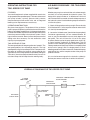
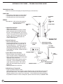
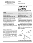
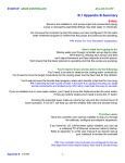
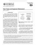
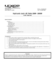
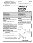
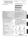
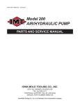
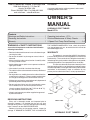
VESTIL MANUFACTURING CORPORATION
2999 North Wayne St., P.O. Box 507
Angola, IN 46703 USA
Phone (260) 665-7586 • Fax (260) 665-1339
www.vestil.com • [email protected]
Revised 0307
21-126-103
A company dedicated to solving ergonomic and material
handling problems since 1955.
OWNER'S
MANUAL
HYDRAULIC POST TABLES
Model HT-A
Contents
Warnings and Safety Instructions .................... 1
Receiving Instructions ..................................... 1
Warranty .......................................................... 1
WARNINGS & SAFETY INSTRUCTIONS
Insure that all employees understand and follow the
following instructions.
• Read and understand the owner's manual before using or
servicing the table.
• Do not use the table if any damage or unusual noise is
observed.
• Always watch the table and any load on it carefully when
it is being moved or used.
• Avoid sudden stops or quick turns to prevent accidental
tipping of the table.
• Use caution if you slide a load onto the table top.
• The table's load must be centered and evenly distributed
on the table.
• Do not perform any modifications to the table without the
manufacturer's approval. Failure to receive authorization
for changes to the equipment could void the warranty.
• Maintenance and repairs are to be done only bypersonnel
qualified to perform the required work.
• Do not use brake fluid or jack oil in the hydraulic system.
If oil is needed, use an anti-wear hydraulic oil with a
viscosity grade of 150 SUS at 100°F, (ISO 32 @ 40° C),
or a non-synthetic transmission fluid.
• Use only replacement parts either supplied or approved
by the manufacturer.
RECEIVING INSTRUCTIONS
Every unit is thoroughly tested and inspected prior to
shipment. However, it is possible that the unit may incur
damage during transit. If you see damage when unloading,
make a note of it on the SHIPPER RECEIVER.
Remove all packing and strapping material, inspect for
damage. IF DAMAGE IS EVIDENT, FILE A CLAIM WITH
Operating Instructions - HT-A .......................... 2
Routine Maintenance & Safety Checks ........... 2
2-Speed Foot Pump Parts/Drawing ..............3-4
THE CARRIER IMMEDIATELY! Also, check the platform
size, type of power unit, etc., to see that the unit is correct for
the intended application.
WARRANTY
This product is warranted for 90 DAYS from date of
purchase to be free of manufacturing defects in material and
workmanship. The manufacturer's obligation hereunder is
limited to repairing such products during the warranty period,
provided the product is sent prepaid back to the factory.
This warranty does not cover normal wear of parts or
damage resulting from any of the following: negligent use or
misuse of the product, use or application contrary to installation
instructions, or disassembly, repair or alteration by any
person prior to authorization from a factory representative.
2-POST
4-POST
SINGLE POST
HYDRAULIC POST TABLES
1
OPERATION INSTRUCTIONS - HT-A
LOADING:
The load rating, in pounds, is shown on the capacity tag located on the base. It indicates the net capacity of the table, assuming
a centered load. Permanent damage to the table or injury to personnel could result from exceeding the listed capacity.
The load size should not exceed the table dimensions by more than 50% and should not exceed twenty-four inches in height.
Do not use the base of the hydraulic table as a storage shelf.
OPERATION:
The manually-powered hydraulic tables are furnished with a foot-pump. On the single and two-post tables, step on the foot
treadle to raise the table and step on the release lever on the right side of the pump to lower the table.
The four-post table has a two-speed foot pump, separate from the lifting cylinder. Step on the foot treadle to raise the table.
You can change the pump from the low-volume to high-volume by pulling the slide on top of the foot pump back toward the
foot treadle.
SAFETY:
Keep all personnel clear of the machine when it is in operation.
Do not exceed the table's load rating.
Use caution to avoid tipping the table when placing or sliding a load onto or off of the table.
Avoid obstacles that can cause the base to sudden stop when moving a loaded table, such as cracks in the floor or the corners
of machines, etc. Doing so could cause the post table to tip over or allow the load to slide off the table.
Never use the table if it is in need of repairs or if it seems to be malfunctioning.
Notify your maintenance personnel if you notice anything out of the ordinary, such as odd noises, erratic motion, or damage
to any part of the table or its components.
ORDERING REPLACEMENT PARTS:
We take pride in using quality parts on the equipment we manufacture. We are not responsible for equipment problems resulting
from the use of unapproved replacement parts.
To order replacement or spare parts for this equipment, contact the factory.
In any communication with the factory, please be prepared to provide the machine's serial number, which is indicated on the
machine dataplate.
ROUTINE MAINTENANCE & SAFETY CHECKS - HT, LDLT
Care should be taken to identify all potential hazards and comply with applicable safety procedures before beginning
work. Only qualified individuals trained to understand mechanical devices and their associated electrical and hydraulic
circuits should attempt troubleshooting and repair of this equipment.
2
(A)
Before each use inspect the following, where applicable:
1.) Oil leaks.
2.) Pinched or chafed hoses.
3.) Damage or structural deformation to the structural members, the cylinder, the foot pump, etc.
4.) Unusual noise or binding or evidence thereof.
(B)
Inspect monthly for, where applicable:
1.) The oil level. Oil should be 1" to 1 1/2" below the cylinder's or the reservoir's fill hole with the lift in
the fully lowered position.
2.) Oil leaks.
3.) Worn or damaged hydraulic hoses and electrical wires, if applicable.
4.) Integrity of the retaining rings and pins at all pivot points.
5.) Looseness, wear, or damage to the casters' bearings, mounting hardware, or surface material.
6.) Unusual noises.
7.) Information and warning labels being in place and in good condition.
8.) The need to clean off dirt and debris.
(C)
Yearly inspection
The oil should be changed if the oil darkens, becomes gritty, or turns a milky color (indicating the presence
of water). Replace with an anti-wear hydraulic oil with a viscosity grade of 150 SUS at 100°F, (ISO 32 @ 40°C).
Ex: AW 32 or HO 150 hydraulic fluid, or non-synthetic transmission fluid.
OPERATING INSTRUCTIONS FOR
TWO- SPEED FOOT PUMP
AIR BLEED PROCEDURE FOR TWO-SPEED
FOOT PUMP
FEATURES:
Your new lift equipment has been supplied with an exclusive
single-speed or two-speed foot pump. The internal features of
your pump includes a primary pressure relief, pressure
compensated return flow control valve, and an integrated
lowering valve. Replacements are necessary.
Whether your pump is a new installation, or has been recently
serviced, air has likely entered the hydraulic system. The
design of this pump includes an "air bleed screw" which will
aid in the removal of unwanted air from the foot pump area of
the hydraulic system. Use the following steps to remove this
air from the system.
OPERATING INSTRUCTIONS:
Stay clear of moving parts. The platform will rise as the foot
pedal is pumped. Depressing the release lever will lower the
table at a controlled rate of descent. In the event the platform
has been overloaded, the pressure relief will open because of
excessive pressure buildup in the hydraulic system. Oil will
bypass into the reservoir. Never increase the pressure relief
setting more than necessary. Do not exceed the rated
capacity of your equipment.
1) Check all fittings to be sure they are tight. Ensure that the
oil is filled to within 1" of the top of the reservoir when the lift
is in the fully lowered position.
TWO-SPEED SELECTION:
The two-speed hydraulic foot pump offers two "speeds". The
low speed products low volume/high pressure. The high
speed products high volume/low pressure. The operator has
the option of selecting the optimum pump speed for the
application at hand. Pump speeds are selected by sliding the
"lock collar" (Item #2 on the parts identification) in or out. An
occasional drop of oil will keep the collar working freely.
2) Locate the "air bleed screw" (item #34 on the pump body)
and loosen approximately 1/2 turn counterclockwise. As
soon as you have loosened the screw, slowly depress the
foot pedal. This unit will force the air out of the pump
chambers. Before you let the pump pedal return to the "up"
or "home" position, tighten the air bleed screw. This will
prevent air from reentering the pump chamber. Repeat the
above procedure until the pump chamber is completely filled
with oil and a "spongy" feel is no longer present. If the air
bleeding procedure has been successful, the feel of the pump
pedal will be firm and the complete stroke of the pump will
produce fluid flow.
Air can also become trapped in the hydraulic cylinder(s).
Review your owners manual for air removal instructions.
HYDRAULIC DIAGRAM FOR TWO-SPEED FOOT PUMP
PRESSURE COMPENSATED
FLOW CONTROL
2 SPEED
FOOT PUMP
PRESSURE
CHECK VALVE
1GPM
TO CYLINDER
ADJ. PRESSURE
RELIEF VALVE
PRESSURE
CHECK VALVE
LOWERING
VALVE
3
HYDRAULIC FOOT PUMP --- TROUBLE SHOOTING GUIDE
TROUBLE SHOOTING
(Read all instructions thoroughly prior to performing any maintenance.)
SYMPTOMS
• Foot pumping action does not raise platform.
• Cylinder slowly drifts downward under load.
• Cylinder pumps up, but will not go down.
CYLINDER
ROD
BLEEDER SCREW
REMEDY
Tools required: 3 & 5 mm hex key wrenches
Standard head screwdriver
Adjustable wrench
FLUID FILL
FILL/
BREATHER
PLUG
PUMP PEDAL
LINE
1) Adjust Release Pedal
(Refer to figure below)
• Loosen setscrew on release pedal. Rotate
pedal counterclockwise until pedal touches
the base. While holding pedal, use hex key
wrench to turn release shaft counterclockwise
to stop. (NOTE: Do not loosen lock nut on
release pedal shaft.) Tighten pedal set
screws. Release pedal.
2) Check Fluid Level
• Remove fill/breather plug.
• Fluid should be filled to 2-2 1/2 inches from
bottom edge of hole when cylinder rod is in
the lowered position. If overfilled, fluid may
seep from fill/breather plug. (ISO #AW-32
ANTIWEAR HYDRAULIC PUMP OIL ONLY.
FLUID MUST BE CLEAN! STRAIN FLUID IF
NECESSARY).
RELEASE VALVE
ASSEMBLY CAP
RELEASE
PEDAL
RELEASE PEDAL
3) Clean Release Valve Assembly
• Remove release valve assembly cap and
clean assembly (shown in exploded view.)
• While assembly is removed, pump foot pedal
vigorously at least five times.
CAUTION: Fluid will discharge from release
valve hole. This will dislodge any foreign
matter from the ball socket. Clear hole of
PRODUCT BASE
debris and reassemble release valve and
tighten cap.
• Repeat procedure #2 to refill fluid.
OVERLOAD BYPASS
ADJUSTMENT SCREW
3 mm HEX
KEY WRENCH
PEDAL SET
SCREW
CCW
MOTION
RELEASE PEDAL
ADJUSTMENT
4) Bleed Pump of Trapped Air
• Pump up cylinder at least 4 inches.
While putting pressure on the platform, release bleeder screw until fluid flows free and clear
from behind the screw. Then tighten bleeder screw and release pressure from platform.
Repeat procedure until no signs of air are present. If after following the above procedures
the problem still exists or if unit is leaking fluid, please contact the factory at (260)665-7586.
4