1
Caution: This document contains mixed page sizes (8.5 x 11 or 11 x
17), which may affect printing. Please adjust your printer settings
according to the size of each page you wish to print.
BGD, NHD
Printed in U S A .
965-0529
5-92(Spec A-G)
Safety Precautions
Before operating the generator set, read the Operalor's
Manual and becMne familiar with it and the e uipment. Safe
and efficient operation can be achieved e& If the unit is
properly operated and maintained. Many accidents aie
caused by failure to fdlow fundamental rules and pr.ecaUtons.
The following sym&ls,found throughout this manual, alert you
to potential dangerouscdionstothe operator,senrice p r sonnel, or e equipment.
mis symbol warns of immediaie hazards which will reswlt in severe personal injuty or
Keep your hailds away .frommoving prts.
Make sure that fasteners on the generator set are secure.
Tighten supports and clamps, keep guards in position over
bns, drive belts, etc.
Do not wear loose clothing or jewelry while working on generator sets. Loose clothing and jewelry canbecome caught
in moving parts. Jewelry can short oui electrical contacts
and cause shock or burning.
2
ifadjustmentmustbemadewhiletheunitisrunning, useexireme caution around hot manifolds, moving parts, etc.
ELECTRICAL SHOCK CAN CAUSE SEVERE PERSONAL
INJURY OR DEATH
death.
Thissymbol refersfo a hazard ur unsafe
practice which can result in severe personal 1nju)y
or death.
1-1
Jhls symboirel'ers tua hazard or unsafe
practice which can iesult in personal injury or prod-
uct or property damage.
FUEL AND FUMES ARE FLAMMABLE. Fire, explosion, and
personal injury can result from improper practices.
DO NO7 5ll,fueltanks while engine is running. Fuel contact
with hot engine or exhaust is a potential fire hazard.
DO NOTSMOKEOR US€AN OPW F ! Enear the generator sei or fuel tank
Fuel lines must be adequately secured and free of leaks.
Fuel connection at the engine should be made with an a p
proved flexjbie, non-corxiuctive iine. Do not use
pip
n g on flexible lines as copper will work harden zm b e m e
brittle.
Be sure all fuei suppiieshave a positive shutoff valve.
GASOLINE AND k?G FUEL MAY BE ACClDENTALLY 1GNlTEDBYELECTRICALSPARKS, resentingWe hazard of
fire or ex+ion,
which can resui in severe personal injury or death. When Installing the generator set:
Do not lie electrical wiring to fuel lines.
Do not run electrical lines and fuel lines through the same
compattment openings.
e Keep elecirical and fuel lines as far apart as possible.
e Place a physical barrier 'miween fuel lines and electrical .
lines wherever possible.
o If electrical and iuel lines must passthroughthe same cornpartment opening, make certain that they are physically
separated by running ' h m through indiiidual channels, or
by passingeach line iihrcugh a separate piice d tubing.
e DO NOT SMOKEwhile servicing batteries. 'Lead acid batteries emit a highiy explosive hydrogen gas that can be ignited by electrical arcing or by smoking.
EXHAUSTGASESAREDEADLY
Neversleep in the vehicle with the generatorset running un- less vehicle is equipped with an operating carbon monoxide
detector.
Provide an adequate e$aust system to properly expel discharged gases. inspect exhaustsystem daily for.leaks per
the maintenance schedule. Be surethatexhaust manifolds
are secure and not warped. Do not use exhaust gases to
heat i!compartment.
e Be sure the unit is well ventilated.
MOWNG PARTS CAN CAUSE SEVERE PERSONAL INJURY OR DEATH
%fore starting work onthe generatorset,disconnect batteries. This will prevent accidentalarcing.
cogper
,.
i
'
s
#
Disconnect starting battery before removing protective
shieldsortouching eiectrical equipment. Use rubber insula3ve mats placed on dry wood platforms over floors that are
metal or concretewhen around electrical equipment. Do not
wear dam polothing (particulariyweLshoes)orallow skin surfacesio be damp when handiing electrical equipmefit.
Use exireme caution when wor!dng on electrical components. High voltagescan cause injury or bath.
Follow all a t e and local elecbkaicodes. Have all electrical
installations priormed by a qualified licensed electrician.
Tag open switchesio avoid accidental closure.
DO NOT CONNECT GENERATOR SET DIRECTLY TO
ANY SUlLDiNG PCTRICAL SYSTEM. Hazardousvoltagescan low from ihegeneratorset into the utility he. This
creates a potential for electrocution w property damage.
Connect onlythroughan approved device and after building
main switch is open. Consult an electrician in regard 20
emergency power *e.
GE~JE~AL
SAFETYPRECAUTIONS
Have afire extinguisher nearby. Maintain exiinguisher properly and become familiar with its use. Extinguishers rated
ABC by the NFPA are appropriate forat1appiications. Consult ihe local fire deparhent for the ecrreci t y j o~f extinguisher for various applications.
Hot ccoiants under pressure can cause severe personal injury. DO NOTopen a radiator presswe cap while the engine
is running. Stop the engine and carefully bleed the system
pressure.
3enzeneand lead,found insome gasoline, hsve been iden-
titled by somestate and federal agenciesas causing cancer
or reproductive toxicity. When checking,draining or adding
gasoline, take care not to ingest, breathethe fumes, or contactgasoline. .
Used engineoils have &en identified by some siate or federal agencies as causing cancer or reproductive toxicity.
When checking or changing engine oil, take care not to ingest, breathe the fumes, or contact used oil.
\Removeall unnecessarygrease and oil from the unit. Accumulated grease and oii'can cause overheating and engine
damage, which presents a potential fire hazard.
DO NOT store anything in the generatorcompartment such
asoil or gas cans,oily rags,chains,wooden blocks, portable
propane cylinders, etc. A fire could result cr the generator
set operation (cooling, noise and vibration) may be adversely affected. Keep the ccmpartmentfloor clean and dry.
Do not work on this equipment when mentally or physically
fatigued, or after consuming any alcohol or drug that makes
Redistribution
or publication
oi equipment
unsafe.of this document,
ihe operation
by any means, is strictly prohibited.
RV-9
"
I
Table of Contents
SECTION TITLE
PAGE
Inside Front Cover
SAFETY PRECAUTIONS
1
INTRODUCTION ................................................. 1-1
..............................
2
3
4
5
About this Manual ............................................... 1-1
Model Identification .............................................. 1-1
GENERAL SPECIFICATIONS ....................................... 2-1
DIMENSIONSAND CLEARANCES .................................. 3-1
TORQUE SPECIFICATIONS ........................................ 4-1
PREPARING FOR SERVICE ........................................ 5-1
Troubleshooting ..................................................
Special Tools ...................................................
Safety Considerations ............................................
Set Removal Guidelines ..........................................
6
7
8
9
5-1
5-1
5-1
5-2
ENGINE PRIMARY SYSTEMS ..................................... 6-1
Introduction .................................................... 6-1
Troubleshooting Engine Primary Systems .......... :................. 6-1
Exhaust System ................................................
6-4
Cooling System ................................................. 6-7
Electronic Ignition System ......................................... 6-9
Breaker Point Ignition System .....................................
6-11
Crankcase Ventilation System .................................... 6-13
Cylinder Compression Test ....................................... 6-14
6-14
Governor .....................................................
Fuel System .Gasoline .......................................... 6-16
Fuel System .LPG Liquid Withdrawal ............................... 6-25
Fuel System .LPG Vapor Withdrawal ............................... 6-31
Electric Starter ................................................. 6-32
CONTROL ...................................................... 7-1
Introduction ....................................................
7-1
Control Description ............................................... 7-1
Control Operation ................................. ............. 7-3
Testing Control Board A I .......................................... 7-3
Control Troubleshooting ........................................... 7-4
GENERATOR ....................................................
8-1
Generator/Control Component Descriptions ............ : .............. 8-1
Generator Operation .............................................
8-3
8-4
GeneratorTroubleshooting ........................................
Generator Service ............................................... 8-6
Brushes and Slip Rings ........................................... 8-9
GeneratorTesting .............................................. 8-11
Testing Voltage Regulator VR1 .................................... 8-13
ENGINE BLOCK ASSEMBLY .......................................
9-1
General ....................................................... 9-1
Oil Filter and Adapter Service ...................................... 9-1
CylinderHeads ................................................. 9-1
Valve System ..................................................
9-2
Redistribution or publication of this document,
.
i
by any means, is strictly prohibited.
SECTION TITLE
.................................................... 9-7
Governor Cup .................................................. 9-8
Timing Gears and Camshalt ....................................... 9-8
LubricationSystem .............................................. 9-9
Piston Assembly ............................................... 9-10
Crankshaft .................................................... 9-14
Cylinder Block .................................................
9-14
Gear Cover
10
.
Bearings .....................................................
9-17
Oil seals ..................................................... 9-18
SERVICE CHECKLIST ............................................10-1
Mounting .....................................................
10-1
Lubrication ....................................................
10-1
Wl&g ....................................................... 10-1
InitialSiart Adjustments ..........................................
10-1
outputcheck ..................................................
10-1
Exhaust system . .....:.......................................
10-1
Fuel System ...:...............................................
10-1
Corltrol ....................................................... 10-1
Mechanical ...................................................
10-1
WIRING WAGRAMS ..............................................
11-1
-
11
I
ii
Redistribution or publication of this document,
by any means, is strictly prohibited.
Section 1 Introduction
ABOUT THIS MANUAL
This manual provides service information for the Onan
BGD and NHD series commercial vehicle generator
sets. This manual describes troubleshooting, disassembly, repair, reassembly, and adjustments to the
engine, generator, and control system. The technician
must understand basic principles of electrical generation and gasoline engine operation. Basic information
can be found in the following Onan publications:
ElectricaVMechanical Fundamentals
(publication 932-0408)
Onan Generator Training Manual
(publication 932-0404)
Installation must comply with the applicable codes and
standards (see the Installation Manual). Improper servicing may create an unsafe installation,resulting in damage to the vehicle and equipment or severe personal
injury or death to the user. Read all service procedures
completely before beginning any repair work, and
observe all cautions and warnings.
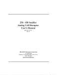
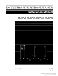
MODEL IDENTIFICATION
When contacting an Onan dealer or distributor, supply
the completemodel number:and serial numberfrom the
set nameplate. This informationidentifiesthe set when
ordering replacement parts.
Always use genuine Onan replacement parts, obtained
from an authorized Onan dealer or distributor. Other
replacementparts mightnot perform to Onan specifications.
BGD and NHD Operator's Manual
(publication 985-01 30)
BGD and NHD Installation Manual
(publication 965-0629)
Incorrect service or repjacement of
Iinjuty
aWARNl
N
GI
parts can result in severe personal
and/or equipment damage. Service personnel
must be qualified toperformelectricaland/ormechani d service.
$PARK
PLUG
CARBURETOR AND
GOVERNOR
ADJUSTMENTS .
SPARK
PLUG
AIR
CLEANER
BRACKET WITH RELAYS
AND BAllERY CHARGING
VOLTAGE REGULATOR
TERMINAL FOR THE
EGATlVE(-) BAllERY
SHAFT MODELS)
COOLING AIR
ER OUTPUT LEADS
FUEL PUMP AND
THE EXHAUST
FLANGE IS
ACCESSIBLE
THROUGH THE
FAN HOUSING
DISCHARGE
OPENING
MOUNllNG TRAY
FOR NEGATIVEI-]
',!!!!$&$E
FIGURE 1-1. TYPICAL GENERATOR SET
1-1
REMOTE CONTROL
WIRE HARNESS
RECEPTACLE
M-1600-15
Redistribution or publication of this document,
by any means, is strictly prohibited.
Redistribution or publication of this document,
by any means, is strictly prohibited.
Section 2. Specifications
W D E L BGD
MODEL NHD
204 pounds (92 kg)
230 pounds (104kg)
General
.
Weight
Overall Dimensions (H x L x W)
Minimum Free
Area for Ventilating Air
Minimum Vertical
ClearanceAt Air Discharge Outlet
ExhaustTailpi
Diameter anc~kterid
Contrd Panel Fuse (Fl)
I nition/ Choke Fuse (F2)
( k ginning Spec Fj
14 x 25114 x 19 in.
(356 x 641 x 478 mm)
1448 x 2!5-9/16 x 21-1/16 in.
(371 x 649 x 535 mm)
85 sq. in. (548sq. cm)
85 sq. in. (548sq. cm)
2 in. (51 mm)
2 in. (51 mm)
1-3/8 in. ID,18 Gauge
1-318 in. ID, 18 Gauge
Rigid SteelTubing
5 ampsSIOW-BIOW
Rigid Steel Tubing
5 amps SIM-BIOW
10 amps
10 amps
Displacement
compressionRatio
47.7 in3 (782 c m 3 )
Bore
325 in. (82.6 mm)
60 in3 (983 cm3)
7-03
3.56 in (90.4 mm)
EnSl-
stroke
Cylinder Compression (Hot)
Spark Plug Gap
Valve Lash
Intake
Exhaust
EngineOil Capacity (Dry Filter)
Swc F
Phor to Spec F
Ignition Timing
Electronic (Non-adjustable)
Breaker-Point(Typical)’
Breaker-PointGap’
Fuel Connections
Maximum Gasdine
Supply Pressure (at Cqrburetor)
Maximum Gasdine Fuel Pump Lift
t
3
GasolineSupply F ~ n g
Min. - Max. Propane Supply
Pressure (Vapor Withdrawal)
PropaneSupply
Connection(VaporWithdrawal)
Propane Supply
Connection(Liquid withdrawal)
6.93
287 in. (729 mm)
3.00 in. (762mm)
75-115 psi (517-793 kPa)
1O(1.120 psi (690-827kPa)
0.025 in. (0.64 mm)
0.025 in. (0.64 mm)
0.005 in. 0.127 mm
0.013 in. 10.330 mmi
0.005 in. 0.1 27 mm
0.013 in. 10.330 mmj
3.5 quarts (3.3 L)
4.0 quarts (3.8 L)
3.5 quarts (3.3 L)
4.0 quarts (3.8 L)
140-180 BTC
200 BTC
0.01 6 in. (0.41 mm)
14’-180 BTC
200 BTC
0.01 6 in. (0.41 m m y
6psi (41 kPa)
6 psi (41 kPa)
3 Ft. (0.9
m)
3 Ft. (0.9
114 in. ID Hose Barb
7-14in.
m)
114 in. ID Hose Barb
(178-356mm) WC
7 - 14 in.
(178 356 mm! WC
3/4 in. NPTFTapping
3/4 in. NPTFTapping
1/4 in. NPTFTapping
1/4 in. NPTFTapping
-
’- Spec A for Model BGDand Specs A and B for Model NHD.
*’
- 0.021 in. (0.53 mm) for LPG.
2-1
Redistribution or publication of this document,
by any means, is strictly prohibited.
Specifications (Cont.)
MODEL BGD-
MODELNHD
12
$2
8
. t4.4
f4.6
50
$0
0.5
4.0 kW
4.5 kW
6.5 kw
5.0 kw
-
4551227alnps
2t.Wl0.5 amps
-
-
54a27.1 amps
26.3/132 amps
-
-
21?.I 10.8 amps
-
0.73 gph (2.8 uh)
0.8 gph (3.0 Uh)
0.53 gph (20 Vh)
0.6 gph (2.3 Uh)
0.8 gph (3.0 uh)
057gph(22L/h)
0.35 gph (13 Vh)
0.4 gph (1.5 Uh)
0.35 gph (1-3 Uh)
0.4 gph (1.5 lfh)
3.5 kW
4.0 kW
At 7 l O m O V o k
31M 5 . 9 amps
-
45.w22.7amps
-
At 120l240 volts
-
3 3 3 16.7 amps
-
522326.3 amps
Propane Fueledsets
Rated PawerOutput
51 3 15.7 amps
'
13 gph (4.9 lfh)
'
0.7 gph (25lfh)
FuU-Load~Cwrenl '
(1-Phase Generators)
Propane Consumption
'
r
Under FulCLoad
0.98 gph (3.7Uh)
1.3 gph (4.9 Uh)
Under Half-Load
0.65 gph (2.5 Uh)
UnderNdoad
0.4 gph (1.5 Uh)
0.8 gph (3.0 uh)
1.18 gph (4.5 Uh)
0.78 gph (3.0 Uh)
1J gph (6.4Uh)
1.05 gph (4.0 Vh)
0.5 gph (1.9 vh)
0.5 gph (1.9 Uh)
0.65 gph (2.5 uh)
-These values are for generators having a Series-Delta connection.
Redistribution or publication of this document,
by any means, is strictly prohibited.
2-2
Section 3. Dimensions and Clearances
I
I
I
BGD
MODELS
NHD
I
I
CYLINDERS AND
PISTONASSEMBLY
Cylinder Bore*
(Std size honed)
3.2490-3.2500
(82.52-82.55 mm)
3.5625-3.5635
(90.49-90.51 mm)
Cylinder Taper
(Max)
0.005
(0.1 3 mm)
0.003
(0.08 mm)
Cylinder Out Of
Round (Max)
0.003
.
(0.08 rnrn)
0.003
(0.08 mm)
Clearance In
Cylinder
.
.
0.0033-0.0053
(0.084-0.1 35 mm)
0.0070-0.0090
(0.178-0.229 mm)
Ring Gap
0.01 0-0.020
(0.25-0.50 mm)
0.01 0-0.020
(0.25-0.50 mm)
Piston Ring #1 (top)
Groove Width
0.0602-0.061 2
(1.53-1.55 mm)
0.0602-0.061 2
(1.53-1.55 mm)
Piston Ring#2
Groove Width
.
Values are in inches (millimeters) unless specified otherwise
I
~~
~
~
_
_
0.0602-0.061 2
(1.53-1.55 mm)
0.0602-0.061 2
(1.53-1.55 mm)
Piston Ring #3
Groove Width
0.1 193-0.1203
(3.03-3.06 mm)
0.1 193-0.1203
(3.03-3.06 mm)
Piston Ring #1 (top)
Groove Width Prior to Spec F
-
0.080-0.081
(2.03-2.06 mm)
0.080-0.081
(2.03-2.06 mm)
Piston Ring #2
Groove Width - Pdor to Spec F
0.080-0.081
(2.03-2.06 mm)
0.080-0.081
(2.03-2.06 mm)
Piston Ring #3
Groove Width - Prior to Spec F
0.1 88-0.1 89
(4.78-4.80 mm)
0.1 88-0.1 89
(4.78-4.80 mm)
Piston Ring #1 (Top)
Side Clearance
0.003-0.008
(0.076-0.203 mm)
0.002-0.008.
(0.051-0.203 rnm)
Piston Pin
Diameter
0.6875-0.6877
(17.46-1 7.47 mm)
0.7500-0.7502
(19.05-19.06 mm)
Piston Pin Fit
In Rod
0.0002-0.0007
(0.005-0.01 8 mm)
0.0002-0.0008
(0.005-0.020 rnm)
Connecting Rod
Side Clearance
0.002-0.01 6
(0.051 -0.406 mm)
0.002-0.01 6
(0.051-0.406 mm)
Connecting Rod
Bearing Clearance
0.0020-0.0033
(0.051 -0.084 rnm)
0.002-0.0033
(0.051-0.084 mm)
,
*The bore is 0.005 inches oversize if the engine serial number has suffix "€.
3-1
Redistribution or publication of this document,
by any means, is strictly prohibited.
MODELS
BGD
NHD
1.9992-2.0000
(50.780-50.800 rnm)
1.9992-2.0000
(50.780-50.800 mm)
1.6252-1.6260
. (41.280-41.300 mm)
1.6252-1.6260
(41.280-41.300)
2.0024-2.0034
(50.860-50.886 mm)
2.0015-2.0040
(50.838-50.902 rnm)
0.0024-0.0042
(0.061-0.1 07 mm)
0.0024-0.0042
(0.061 -0.107 mm)
0.006-0.01 2
(0.15-0.30 mm)
0.006-0.012
(0.1 5-0.30 mm)
Camshaft Journal
Diameter
1.3740-1.3745
(34.90-34.91 mm)
1.3740-1.3745
(34.90-34.91 mm)
Camshaft Bearing
Diameter
1376-1.377
(34.95-34.97 mm)
1.376-1.377
(34.95-34.97 mm)
CamshaItBearing .
Ctearance
0.0015-0.0030
(0.038-0.076 mm)
0.0015-0.0030
(0.038-0.076 mm)
(0.01 1-0.048)
(0.28-1.2 mm)
0.01 1-0.048
(0.28-1.2 mm)
Valve Spring Free
Length
1.600
(40.64 rnm)
1.662
(42.21 rnm)
Valve Spring Compressed
Length (valve ctosed)
1.346
(34.19 mm)
1.375
(34.92 mm)
Valve Spring Tension
Open
55 Ibs
(25 kg)
71 Ibs
(32 kg)
Valve Spring.Tension
Closed
25 Ibs
(11 kg)
38 Ibs
(17 kg)
CRANKSHAFT AND
CAMSHAFT
Crankshaft Main Bearing
Journal Diameter
Crankshaft Rod Journal
Bearing Diameter
I
Crankshaft Main
Bearing Diameter
'
Crankshaft Main
b r i n g Clearance
.
Crankshaft End
Play
Camshaft f n d Play
I
VALVE AND LIFTERS
1 '
.
'
,I
,
3-21
Redistribution or publication of this document,
by any means, is strictly prohibited.
MODELS
,
I
I
BGD
NHD
Valve Face Angle
44"
44"
Valve Seat Angle
450
45
Valve Stem
Diameter (Intake)
0.2795-0.2800
(7.099-7.1 12 mm)
Valve Stem
Diameter (Exhaust)
(7.061 -7.074 mm)
Valve Guide
Diameter
0.3425-0.3430
(8.700-8.712 mm)
..
0.2780-0.2785
Intake
0.2810-0.2820
(7.137-7.1 63 mm)
Exhaust
0.2805-0.281 5
(7.125-7.1 50 mm)
0.341 0-0.3420
(8.661 -8.687 mm)
Intake and Exhaust
0.344-0.346
.
(8.74-8.79 mm)
Valve Stem
Clearance (Intake)
0.0010-0.0025
(0.025-0.064 mm)
0.001 0-0.0025
(0.025-0.064 mm)
Valve Stem
Clearance (Exhaust)
0.0020-0.0035
(0.051-0.089 mm)
0.0025-0.0040
(0.064-0.1 02 mm)
Valve Lifter Diameter
0.7475-0.7480
(18.987-1 8.999 mm)
0.7475-0.7480
(18.987-1 8.999 mm)
Valve Lifter Bore
Diameter
0.7500-0.751 5
(19.050-1 9.088 mm)
0.7500-0.751 5
(19.050-19.088 mm)
Valve Lifter To
Block Clearance
0.0020-0.0040
(0.051 -0.1 02 mm)
0.0020-0.0040
(0.051 -0.1'02 mm)
Intake Valve Seat
Diameter (Outside)
1.470-1.471
(37.34-37.36 mrn)
1.569-1.570
(39.85-39.88 mm)
Exhaust Valve Seat
Diameter (Outside)
1.192-1.193
(30.28-30.30 mrn)
1.255-1.256
(31.88-31.90 mm)
~
Valve Seat Bore
Diameter (Intake)
Valve Seat Bore
Diameter (Exhaust)
1.4395-1.4405
(36.563-36.588 mrn)
1.I 89-1.190
(30.20-30.23 mm)
3-3
-
1.5645-1-5655
(39.738-39.764 mm)
1.2510-1.2520
(31-775-31.801 mrn)
Redistribution or publication of this document,
by any means, is strictly prohibited.
,
Redistribution or publication of this document,
by any means, is strictly prohibited.
Section 4.Torque Specifications
MODELS
BGD
Use engine oil as a lubricant for all threads
EXCEPT the spark plug and rotor through-bolt threads.
FOOT-POUNDS
(NMON-METRES)
TORQUE
SPECIFICATIONS
Cylinder Head (Cold)
15-17
(20-23)
Connecting Rod
12-14
(16-19)
Rear Bearing Plate
25-27
(34-37)
Flywheel Mounting Screw
50-55
Oil Base
18-23
(24-31)
Gearcase Cover
8-10
(1 1-14)
11
(15)
Exhaust Manifold
9-1 1
(12-15)
Intake Manifold
6-10
(8-14)
45-55
(61-75)
Starter Mounting Screws
30-33
(41-45)
stator Clamp screws
10-12
(11-16)
Adapter to Engine
Mounting Screws
25-27
(34-37)
30-33
(41-45)
10-12
(11-16)
19-22
(26-30)
28-32
(38-43)
Spark Plug
I Rotor Through-Bolt
I
’
(68-75)
Adapter to Generator
Mounting Screws
Rear Vibration Isolator
-Center Screw
-Flange to Drip
Tray Screws
Front Vibration Isolator
-Flange to Oil
Base Screws
I
-center Screw
I
Redistribution or publication of this document,
by any means, is strictly prohibited.
1
NHD
MODELS
Use engine oil as a lubricant for all threads
EXCEPT the spark plug and rotor through-bolt threads
(NEWTON-M ETRES)
FOOT-POUNDS
TORQUE
SPECIFICATIONS
1
1
Cylinder Head (Cold)
'15-17
(20-23)
Connecting Rod
27-29
(37-39)
Rear Bearing Plate
25-28
(34-38)
50-55
(68-75)
-18-23
(24-31)
8-10
(11-14)
11
(15)
20-23
(27-31)
15
(20)
18-23
(24-31)
7-9
(10-1 2)
Rotor Through-Bolt
45-55
(61-75)
Starter MountingScrews
30-33
(41-45)
10-12
(11-16)
25-27
(34-37)
1
1 oil
I
Flywheel Mounting Screw
Base
Gearcase Cover
1
Spark Plug
Exhaust Manifold
Intake Manifold
Other 3/8 Cylinder Block
Nuts
Oil Pump
I
Stator Clamp screws
Adapter to Engine
Mounting Screws
I
Adapter to Generator
Mounting Screws
25
Rear Vibration Isolator
-Center Screw
30-33
(41-45)
10-12
(11-16)
19-22
(26-30)
-Flange to Drip
Tray Screws
*
Front Vibration Isolator
-Flange to Oil
Base Screws
-Center Screw
'(34) .:
,
'
4
28-32
4-2
(38-43)
Redistribution or publication of this document,
by any means, is strictly prohibited.
Section 5. Preparing to Service
TROUBLESHOOTING
Valve spring compressor
Valve lock replacer
Valve seat driver
Valve guide driver
Slide hammer
Piston groove cleaner
Outside micrometer set (0 to 4 in.)
Telescoping gauge set (112 in. to 4 in.)
Hole gauge (0.300in. to 0.400 in.)
Plasti-Gage bearing clearance guide
The generator set can be divided into four areas for
servicing:
0
Engine - Primary Systems
0
Control
0
Generator
0
Engine Block Assembly
-
Generator and Control:
Lead or dead-blow hammer
Battery hydrometer
VOM multi-tester
Insulation resistance tester (Megger)
Frequency meter
Armature growler
Load test panel and leads
A separate section in this manual covers each area.
Troubleshooting charts define the causes of various
malfunctions.
SPECIAL TOOLS
The tools listed below are necessary to service the
generator set Some of these are available through an
authorized Onan service center; consult the Onan tool
catalog (publication #900-0019).
Engine Tools:
SAFETY CONSIDERATIONS
Generator sets present several hazards that must be
considered to service the unit safely. Study the safety
precautions on the inside front cover of this manual
closely, and become familiar with the hazards listed in
Table 5-1. Approach the job in a safety-conscious
manner, to avoid injury or death.
-
Torque wrench (0 75 ft-lbs or 0-100 Nom)
Feeler gauge
Pressure gauge
Spark plug gap gauge
Cylinder compression tester
Flywheel puller
'
Snap ring pliers
Gear puller with puller ring
Cylinder ridge reamer
Combination main and cam bearing remover
Combination main and cam bearing driver
Oil seal loader and driver
Piston ring compressor
Piston ring spreader
Cylinder hone
Valve seat cutter
Safeguards to Avoid Hazards
0
Use personal protection: Wear appropriate protective safety equipment, such as:
- Safety shoes
- Gloves
- Safety glasses
- Hard hats
Do not.wear rings or jewelry, and do not wear loose
clothing that might get caught on equipment.
5-1
Redistribution or publication of this document,
by any means, is strictly prohibited.
TABLE 5-1
HAZARDS AND THEIR SOURCE
Electrical Shock (AC)
-Improper generator set load connections
-Faulty wiring
-Faulty electricalload wiring
-Faulty generator set wiring
Fire and explosions
-Leaking fuel
-Hydrogen gas from charging battery
-Oily rags improperly stored
-Flammable liquids improperly stored
-Any fire, flame, spark, pilot light,
arc-producing equipment or other ignition
sources
0
0
0
0
0
Rotating Machinery
-Flywheel fan guard not in place
Slippery Surfaces
-Leaking or spilled oil
Burns
-Hot exhaust pipes
-Hot engine and generator surfaces
-Hot engine oil
-Electrical short
-Hot engine coolant
Heavyobjects
-Removing generator set from vehicle
-Removing heavy components
Poisonous Gases
-Carbon monoxide from faulty exhaust
-LP gas leaking into coach interior
-Operating generator set where
exhaust gases can accumulate
Reduce the hazard A safe, orderly workshop area
and well-maintained equipment reducethe hazard
potential. Keep guards and shields in place on
machinery, and maintain equipment in good working condition. Store flammable liquids in approved
containers, away from fire, flame, spark, pilot light,
arc-producing equipment or other ignition sources.
Keep the workshop clean and well-lighted, and
provide adequate ventilation. Keep fire extinguishers and safety equipment nearby, and be prepared to respondto an emergency.
Develop safe work habits: Unsafe actions cause
accidents with tools and machines. Be familiar with
the equipment, and know how to use it safely. Use
the correct tool for the job, and check its condition
before starting. Comply with the warnings in this
manual, and take special precautions when working around electrical equipment. Do not work alone
if possible, and take no risks.
Be prepared to respond to an accident: Agencies
such as the Red Cross and public safety departments offer courses in first aid, CPR, and fire control.
Take advantage of this information to be ready to
respondto an accident Learnto besafety-conscious,
and make safety procedures part of the work
routine.
SET REMOVAL GUIDELINES
Certain service procedures require that the generator
set be removed from the vehicle. The generator set is
normally mounted in a special compartment, on the
vehicle bed, or below the vehicle floor.
Because generator set installationsvary, it is not possible to describe a specific removal procedure. If an
acceptable method cannot be determined, contact the
vehicle manufacturer or the generator set installer for
the preferred method.
Special fuel handling procedures are required to
remove an LPG-powered set. The fuel system must be
purged of LP gas before the set can be removed safely
from the vehicle.
The generator sei is heavy and can
llCE@El
cause severe personal injury if
dropped during removal. Use adequate lifting devices
to provide sufficient support for the set. Keep hands
and feet clear while lifting.
5-2
Redistribution or publication of this document,
by any means, is strictly prohibited.
IBWARNINGJ flammable,
LP gas (Propane) is extremely
and poisonous.
LPG Purging Procedure
Severe personal injury or death can resuit if it is
accidentally ignited orinhaled. Eliminate allpossible sources ofignition including fire,ilame, spark,
pilot light, arc-producingequipment or other ignifion sources before purging LP gas from the fuel
system. Provide adequate ventilation to dissipate
LP gas as it is released.
1. Open the set-mounted AC circuit breakers and
close the shutoff valve at the fuel tank.
2. Start and run the generator set until it is out of fuel.
3. Crank the set a few times after it stops, to make
certain that it is purged of fuel.
4. Slightly open the fuel line (flexible section) at the
solenoid valve, and allow the LP gas to slowly
escape. Do not open the fitting widelya large quantity of gas may be released.
If the generator set cannot be operated, do the following:
Move the vehicle to a well-ventilated outdoor location, far from fire, flame, spark, pilot light, arcproducing equipment or other ignition sources.
5. Disconnect the fuel supply hose from the carburetor, and hold it clear of the set
Disconnect the vehicle negative (-) battery cable
and the generator set negative(-) battery cable from
their respective batteries.
6. Press in and hold the primer button on the regulator
to release LP gas from the set fuel system.
Close the generator set fuel system shutoff valves,
and all other shutoff valves, at the fuel tank.
7. When gas can no longer be heard escaping from
the open end of the fuel supply hose, reconnectthe
hose to the carburetor.
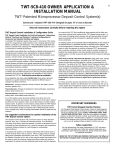
BARRIER
usl121-1
FIGURE 5-1. TYPICAL COMPARTMENT MOUNT INSTALIATION
5-3
Redistribution or publication of this document,
by any means, is strictly prohibited.
DOOR
REAR
PANEL
ASSEMBLY
SUPPORTTFLAY
SUPPORT BRACKET
MS-1122-2
FIGURE 5-2. TYPICAL UNDER-FLOOR INSTALLATION
9. (Gasolinesets) Turn off the fuel shutoff valve in the
compartment and disconnectthefuel lineat the fuel
pump. Securely plug the end of the fuel line to prevent fuel leakage or an accumulation of explosive
gasoline vapor.
Disconnecting Set from Vehicle Systems
Refer to Figures5-1 and 5-2 for component locations in
typical generator set installations.
1. Disconnectthe vehicle negative (-) battery cable at
the battery terminal.
Gasolinevapor is extremely flammable, and can result in severe
personal injury or death if ignited. Make certain all
fuel line openings are plugged to prevent gasoline
vapor from accumulating. Eliminate all possible
sources of ignition including tire, flame, spark,
pilot light, arc-producingequipmenf or other ignition sources before working in fhis area.
AWARNING
2. Disconnect the generator set negative (-) battery
cable at the battery terminal.
3. Disconnect the generator set positive (+) battery
cable from the start solenoid.
4. Disconnect the remote control wire plug from the
generator set control.
(LPG sets) After purgingthe system, disconnectthe
fuel line at the solenoid valve, and plug the end of
the fuel line to prevent contamination.
5. Disconnectthe generator load wires at the vehicle
electrical system junction box. Tag the vehicle circuit wires for positive identification when reconnecting.
6. Loosen the conduit connector, and pull the load
wires and flexible conduit free of the junction box.
7. (Extended-shaft units only) Disconnect any couplings, adapters, or power takeoff-related attachments from the extended shaft of the unit
8. ' Disconnectthe muffler from the exhaust manifoldat
the flange connection. Disconnect any support
brackets or hangers that connect the muffler to the
set.
5- 4
.Removing Above-Floor-Mounted Set
From Vehicle
When the generatorset has been disconnectedfrom the
electrical,exhaustandfuel systems, examine its mounting bolts and sup~ortmembers. The generator set drip
tray is normally -bolted to the vehicle framework.
Depending on ttiainstallation,the set may be removable
from the side, back, or bottom.
Make certain that the set is firmly supported before
loosening any mounting bolts or support members. Use
a forklift, if possible, to lift or move the generator set
Redistribution or publication of this document,
by any means, is strictly prohibited.
,
The generator set is heavy, and can
1Oilin the engine cylinders can cause
engine damage during starting
l.ZEi&l
cause severe personal injury if
affempts. Oil can enter the engine cylinders when the
dropped during removal. Use the recommended removal procedures, and keep hands and feet clear while
removing mounting bolts.
1-
Oilin the engine cylinders can cause
engine damage during starting
aftempts. Oil can enter the cyrinders if the generator
set is in a tilted position. Do not leave fhe set in this
position for more than 30 minutes if the oil has not been
drained.
generator set is in the lowered (tilted)position. Do not
leave the generator set in thisposition formore than 30
minutes if the oil has not been drained.
Partial Set Removal
Fuel, exhaust, electrical and control connections must be disconnected as described previously.
1. Park the vehicle on a level surface which can sup-
portthefloor jack wheels. Putthe transmission in its
PARK position, lock the brakes and remove the
ignition key. Make sure no one moves the vehicle
while performingthis procedure.
Removing Under-Floor-Mounted Set From
Vehicle
When the generatorset has been disconnectedfrom the
electrical, exhaust, and fuel systems, the set may be
partially removed for limited service, or completely
removed for major service. The set is mounted on a
support tray, which serves as the bottom of the underfloor housing. The inner edge of the support tray is
hingedto the rear panel assembly. The outer edge of the
support tray is bolted to a support bracket. (Two
brackets are used on NHD units.) A front and rear panel
assembly serve as sides to complete the housing.
1 - 1*WARN"'
Dropping the generator set can
cause severe personal injury or
death. Make sure no one moves the vehicle during
this procedure and that the procedure is performed
very carefully and only as instructed.
2. Positionafloor jack under the reinforcement ribs of
the drip tray, as shown in Figure 5-3.
3. Raise the jack until it makes contact with the drip
tray, then put slight upward pressure on the tray.
The generator set is completelysuspended underneath
the vehicle by the housingassembly. To avoid dropping
the set during removal, follow the recommended removal procedures.
The generator set is heavy, and can
cause severe personal injury if
dropped during removal. Use the recommendedremoVal techniques, and keep hands and feet clear while
removing mounting bolts.
iiiEiE@
If the generator set will be le%in the down (tilled) position for more
than 30 minutes, first drain the oil.
UNDER DRIP TRAY
REINFORCEMENTRIBS
M-1600-2
FIGURE 5-3. PARTIAL SET REMOVAL
5-5
Redistribution or publication of this document,
by any means, is strictly prohibited.
4. Remove the bolts from the front support brackets
(and the rear brackets, NHD only) and remove the
brackets. This may require slight adjustment of the
floor jack.
4. Remove the bolts securing the side support to the
drip tray and the underfloor bracket. (Also remove
bolts from the rear support bracket, if removing a
NHD unit)
5. When the support bracket is removed, the floor jack
will support all its weight on that side. Slowly lower
the jack, beingcareful to allow the jack to roll asthe
generator set swings downward.
5. Lift the generator slightly until the safety catch on
the side support is clear of the tray. Pull support
forward and upward until disengaged from the tray
and underfloor bracket
6. Supportthedrip tray assembly with wood blocks, so
the floor jack can be removed. This will allow more
access for the service procedure.
6. Remove the side support, to provide the clearance
needed for lowering the set.
rawnR"Gl
7. Remove the safety catch from the center of each
hinge assembly, then remove the U-shaped hinge
pin.
Complete Set Removal
8. Slowly lower the generator set until it is clear of all
obstructions, and can be removed from under the
vehicle.
Make sure generafor is resting
securely before removing floor
jack. Otherwise, the generator set can swing
downward causing severe personal injury.
Fuel, exhaust, electrical and control connections must be dsconnected as described previously.
1. Parkthe vehicle on a level surface which is capable
of supporting the floor jack wheels. Put the transmission in its PARK position, lock the brakes and
remove the ignition key. Make sure no one moves
the vehicle while performing this procedure.
Dropping the generator sef can
cause severe personal injury or
death. Make sure no one moves the vehicle during
thisprocedure and that fhe procedure is performed
very carefully and only as insfrucfed.
2. Use a forklift to supportthe generator set tray at the
points shown in Figure 5-4. Place a wooden block
on one fork so the set will remain level.
3. Raisethe forklift so it contactsthe drip tray, then put
slight upward pressure on the tray. Make certain
that the generator set is supported by the forks
before continuing.
FORK LIFT
/\\'\
'
M-1601-2
FIGURE 5-4. COMPLETE SET REMOVAL
Redistribution or publication of this document,
by any means, is strictly prohibited.
-
Section 6. Engine Primary Systems
INTRODUCTION
The primaryenginesystemscan often beservicedwithout removing the generator set from the vehicle, and
without major disassembly. Use the following troubleshooting guide to help locate problems related to the
engine primary systems. Refer to the Troubleshooting
Generator Set Control section for genset starting
problems.
Primary engine systems include:
0
0
0
0
0
0
0
0
0
0
Exhaust system
Cooling system
Ignition system
Electric starter
Crankcase ventilation system
Governor
Fuel system - Gasoline
Fuel system LPG liquid withdrawal
Fuel system - LPG vap'or withdrawal
Electric starter
Before considering major inspection of the engine due
to abnormal engine performance (engine knocks,
power loss, etc.), refer to the Operator's Manual, (publication 965-0129), Periodic MaintenanceSchedule, for
the procedure to clean the carburetor and combustion
chamber with Onan "4C".
-
TROUBLESHOOTING ENGINE PRIMARY SYSTEMS
AWARNING
Trouble
Engine
Misfires
Unfrainedpersonnel should not attempt repair due fohazards which can resulf in personal
injury or death. Troubleshooting informationis provided for qualifiedrepair personnel onlyPossible Cause
1. Faulty ignition due to:
a. worn or fouled spark plugs.
**b. worn breaker points.
**c. incorrect ignition timing.
d. faulty ignition coil, or
e. faulty plug wires.
**f. faulty condenser.
g. faulty ignition module
(electronic ignition)
la.
b.
c.
d.
e.
2. Lean fuel mixture due to:
a. incorrectly adjusted
fuel mixture screws.
*b. incorrect float level.
c. dirt in carburetor.
d. vacuum leak.
2a. Adjust carburetor main
and idle adjustment screws.
b. Adjust carburetor float level.
c. Disassemble carburetor
and clean all internal passages.
d. Locate leak and correct as required.
3. *Contaminated fuel.
3. Drain fuel tank and refill
with fresh fuel.
4. In cold weather, place air
preheater in winter position.
4. *Carburetor icing.
*Gasoline sets only.
**Prior to Spec B for Model BGD and Spec
C for Model NHD.
'
Engine
Backfires
Corrective Action
Replace spark plugs.
Replace breaker points.
Set breaker point gap.
Test coil and replace if necessary.
Test spark plug wires and
replace if faulty.
f. Replace condenser.
g. See Testing Ignition Module.
1. Faulty ignition due to:
**a. incorrect ignition timing.
b. incorrect spark plug gap.
**c. faulty condenser.
la. Adjust breaker point gap.
b. Reset spark plug gap.
c. Replace condenser.
2. Lean fuel mixture due to:
a. incorrectly adjusted
fuel mixture screws.
*b. incorrect float level.
c. dirt in carburetor.
2a. Adjust carburetor main and
idle adjustment screws.
b. Adjust carburetor float
level.
c. Disassemble carburetor and
. clean all internal passages.
3. Mechanical damage to engine.
*Gasoline sets only.
**Prior to Spec B for Model BGD and Spec
C for Model NHD.
3. See Engine Block Assembly
section.
6-1
Redistribution or publication of this document,
by any means, is strictly prohibited.
TROUBLESHOOTING ENGINE PRIMARY SYSTEMS (Continued)
m
WARNING Untrained personnel should not attempt repair due to hazards which can result in personal
injury or death. Troubleshootinginformation is provided for qualified repair personnel only.
Engine
Lacks Power
Corrective Action
Possible Cause
Trouble
1. Faulty ignition due to:
**a. incorrect ignition timing.
b. incorrect spark plug gap.
2. Dirty air cleaner.
3. Restrictedfuel flow due to:
a. plugged fuel filter or
b. faulty fuel pump.
4. Incorrectfuel mixture due to:
a. incorrectly adjusted
fuel mixture screws.
*b. incorrect float level, or
c. dirt in carburetor.
5.
6.
7.
8.
9.
la.
b.
2.
3a.
b.
4a.
b.
c.
d.
5.
d. vacuum leak.
Exhaust system blocked or
restricted.
Incorrectvalve tappet
clearance.
Excessive engine wear or
damage to engine.
Carburetor air preheater
set incorrectly.
Excessive carbon buildup.
6.
7.
8.
9.
0. No-load speed set too low.
Adjust breaker point gap.
Reset spark plug gap.
Replace air cleaner.
Clean fuel filter.
Test fuel pump and repair or
replace if faulty.
Adjust carburetor main and
and idle adjustment screws.
Adjust carburetor float
level.
Disassemble carburetor and
clean all internal passages.
Repair vacuum leak.
Locate and remove cause
of blockage.
Adjust valve tappets (see
Engine Block Assembly section).
See Engine Block
Assembly section.
In hot weather, place
air preheater in summer position.
Dissassemble and scrape carbon.
10. Adjust governor.
*Gasoline sets only.
**Prior to Spec B for Model BGD and
Spec C for Model NHD.
Engine
Overheats
1. Restricted airflow due to
dirt or debris blocking air
.inlet or outlet
1C l e a r away anydebris that
may restrict airflow to set.
Do not use compartment for
storage area.
2. Clean away all dirt and oil
from engine cooling fins.
3. Adjust breaker point gap.
4a. Adjust carburetor main and
idle adjustment screws.
b. Adjust carburetor float
level.
c. Disassemble carburetor and
clean all internal passages.
2. Dirt or oil covering engine
cooling fins.
3. Incorrect ignition timing.**
4. Lean fuel mixture due to:
a. incorrectly adjusted
fuel mixture screws.
*b. incorrect float level, or
c. dirt in carburetor.
*Gasoline sets only.
Black Exhaust
Smoke
1. Rich fuel mixture due to:
a. dirty air cleaner.
*b. choke sticking.
c. incorrectly adjusted fuel mixture
screws.
d. dirt in carburetor.
1a. Replace air cleaner.
b. Clean choke and choke
linkage.
c. Adjust carburetor idle and
main adjustment screws.
d. Disassemble carburetor and
clean all internal passages.
*Gasoline sets only.
6-2
Redistribution or publication of this document,
by any means, is strictly prohibited.
TROUBLESHOOTING ENGINE PRIMARY SYSTEMS (Continued)
Untrainedpersonnel should not attempt repair due to hazards which can result in personal
injury or death. Troubleshooting information is provided for qualified repair personnel only.
1-1
.
Corrective Action
Possible Cause
Trouble
1. Clean and lubricate
1. Sticking or binding
Engine
Hunts or Surges
governor linkage.
governor linkage.
2. Incorrect governor
adjustment
2. Adjust governor speed and
sensitivity.
3. Faulty governor spring.
3. Replace governor spring.
4. Incorrect fuel mixture due to:
a. incorrectly adjusted
fuel mixture screws,
*b. incorrect float level, or
c. dirt in carburetor.
5. Governor mechanism worn
excessively.
4a. Adjust carburetor main and
idle adjustment screws.
. 4b. Adjust carburetor float
level.
4c. Disassemble carburetor and
clean all internal passages.
5. See Engine Block
Assembly section.
6. In cold weather, place air
preheater in winter position.
*6. Carburetor icing.
f. Replace condenser.
7. Faulty ignition condenser.
*Gasoline sets only.
1. Drain oil and refill with
correct viscosity oil.
High Oil
Consumption
1. Oil viscosity too light or
(Note: New
engines
sometimes
have high oil
consumption
during break-in)
2. Crankcase breather valve is
dirly or defective.
2. Clean crankcase breather
and replace if defective.
3. Oil leaks.
3. Locate source of leak and
repair as required.
4. Excessive engine wear.
4.
5. tight loading.
5. Don’t run set at no-load
for long periods of time.
oil is diluted.
See Engine Block
Assembly section.
~~
Low Oil
Pressure
,
1. Oil viscosity too light or
oil is diluted.
1. Drain oil and refill with
2. Low oil level.
2. Add oil as required.
3. Low oil pressure switch
3. Replace oil pressureswitch
correct viscosity oil.
(seeEngine Block Assembly
defective.
section)
4. Faulty oil bypass valve.
4. Inspect oil bypass valve and
clean or replace as required
(see Engine Block Assembly
section.)
5. Excessive engine wear or
defective oil pump.
5. See Engine Block
Assembly section.
6-3
Redistribution or publication of this document,
by any means, is strictly prohibited.
EXHAUST SYSTEM
Exhaust system condition is extremely critical, because
of the possibility of exhaust gases entering the vehicle.
The exhaust system must be serviced immediately if
inspection reveals leaking joints or connections, loose
fasteners, or broken or damaged components.
Always replace worn components with new Onan
replacement parts. Do not attempt to repair a broken
exhaust pipe or' manifold by welding. Do not replace
worn components with parts that do not meet Onan
specifications. Contact an authorized Onan service
center for exhaust kit parts and installation instructions.
lnhalation of exhaust gases can
result in severe personal injury or
death. Modifying the exhaust system (other than shortening the downpipe) may allow poisonous exhaust
gases to enfer the vehicle. Use only Onanreplacement
parts to service the exhaust system. Unauthorized
modificafions will void the Onan warranty. Liability for
injury or damages due to unauthorized modifications
becomes the responsibilify of the person making the
change.
L BRACKET
Figure 6-1 shows a typical exhaust system for a compartment mount generator set. Figure 6-2 illustrates a
typical exhaustsystem for an underfloor mount generator set Separate service procedurescover each type of
exhaust system. Also refer to the exhaust kit installation
instructions.
Compartment Mount Exhaust System
The exhaust system consists of:
Exhaust manifold
Muffler
Muffler strap
Hanger
Clamps
Tailpipe
Disassembly Procedure:
1. Loosen the front muffler clamp, muffler strap, and
tailpipe hanger. Remove the muffler and tailpipe
assembly. (Figure 6-1)
2. Removethe screws that secure the exhaust tube to
the exhaust manifold. Removethe exhaust tube and
exhaust gasket
MUFFLER STRAP
CUTOUT
HANGER BRACKET
(3 FOOTll METREMINIMUM
FROM DOWNPIPE, OR AT
PERIMBER OF VEHICLE)
FRONT SET VI!%
as-1147-3
....
f
. '.
.
FIGURE 6-1. CONVENTIONAL COMPARTMENT MOUNT EXHAUST SYSTEM
6-4
Redistribution or publication of this document,
by any means, is strictly prohibited.
Completion of the remaining steps requires that the generatorset be
removed from the vehicle. Refer io the Preparing to Service section
for set removal procedures. For LPG sets, follow the procedure for
purging LPG from the fuel line.
8. Support the tailpipe using a shock-mounted support hanger with clamp.
lncorrecf muffleranti failpipe
hanger bracket mounting can
result in excessive vibration fransferfo
the vehicle.
To prevent this, mount the mufflerand tailpipe
hanger brackets directly above the component
being supported, NOT at an angle.
1-
3. Remove the cooling system noise shield and scroll
(see Coolingin this section) to provideaccessto the
exhaust manifold.
4. Remove the screw that secures the exhaust manifold outlet flange to the exhaust manifold support
bracket
9. Run the generator set for five minutes. Check the
entire length of the exhaust system for leaks and
excessive noise. Repair any leaks immediately.
5. Remove the four exhaust manifold screws. Lift off
the exhaust manifold and thetwo manifoldgaskets.
The muffler and exhaust pipe
lnot
aWAR"G1
can ignite grass and brush. Do
operate the generator set when vehicle is
AWARN~NGExhaust gas can produce severe
personal injury or death, i f it is
inhaled. To prevent exhaust leaks, install all gaskets,
clamps, straps, and hardware as specifiedin this manual and other Onan publications.
parked in high grass or brush.
10. Clean the spark arrester muffler every 100 hours of
operation.To do this, removethe 1/ 8 inch pipe plug
in the bottom of the muffler and run the set for five
minutes. Then replace the pipe plug. inspect the
exhaust system for leaks at least every eight hours
of running time.
Assembly Procedure:
1. Install the exhaust manifold using new gaskets.
Tighten the four manifold screws to the specified
torque.
2. Install the 5/16-18 screw, lock washers, and nut
that secure the manifold outlet flange to the manifold support bracket Tighten securely.
Underfloor Mount Exhaust System
Underfloor mount exhaust systems consist of the
exhaust manifold, muffler, clamps, hanger (if
required), and tailpipe. When service is required, disassemble and reassemble as specified in the following
steps.
3. Install the cooling system scroll and noise shield
(see Cooling System in this section).
If no other service is required, install the generator set in the
vehicle before completing the remaining steps.
Disassembly Procedure
4. Install a new gasket between the exhaust manifold
and exhaust tube.
1. Loosen the muffler clamp at the muffler inlet (see
Figure 6-2) and remove the muffler support bracket
screws.
Secure the flange connector to the manifold using
5/16-18 inch capscrews and lock washers.
2. Remove the two 1/4-20 screws and lock washers,
and muffler and tailpipe assembly.
5. Attach the inlet of the muffler to the exhaust tube
using a 1-1 /2 inch U-bolt type automotive muffler
clamp. Makecertainthatthe muffler inletpipeoverlaps the exhausttube a minimum of 1-Minches (38
mm).
I)
Completion of the remaining steps requires that the generator
set be removed from the vehicle. Refer to Preparing to Service
section for set removal procedures. For LPG sets, follow the
procedurefor purging LPG from the fuel line.
6. Placethe muffler strap on the muffler, and positionit
below the cutout in the bottom of the generator set
drip tray. Fastenthestrap to thestrap bracketonthe
set, using a 114-20 screw and lock washer. Tighten
the strap around the muffler using a 1/4-20 screw,
lock washer, and nut
3. Remove the cooling system noise shield and scroll
(see Cooling in this section)to provideaccess to the
exhaust manifold.
4. Remove the four exhaust manifold screws. Lift off
the exhaust manifold and the two manifoldgaskets.
7. If replacingthe originaltailpipe, refer to the Tailpipe
Recommendationssection to select and locate the
tailpipe. Attach the tailpipe to the outlet end of the
muffler. Secure it using a 1-3/8 inch U-bolt type
automotive muffler clamp.
6-5
Redistribution or publication of this document,
by any means, is strictly prohibited.
Assembly Procedure
Exhaust gas can cause severe perTo prevent
exhaust leaks, install all gaskets, clamps, straps, and
hardware as specified.
(BWAR"G( sonal injury or death.
1. Installthe exhaust manifold using new gaskets and
tighten the four manifold screws to the specified
torque.
5. Installthe two 114-20 screwsand lock washers that
secure the muffler support bracket to the set and
tighten muffler clamp.
To prevent excessive vibration
transfer to the vehicle, mount
muffler and tailpipehanger bracketsdirectly above
the component being supported and NOT at an
angle.
1-
2. Replace the noise shield and scroll (refer to the
Cooling System section).
6. If replacingthe originaltailpipe, refer to the Tailpipe
Recommendations section to select and locate the
tailpipe. Attach the tailpipe to the outlet end of the
muffler. Secure it using a 1-3/8 inch U-bolt type
automotive muffler clamp.
If no other service is required, install the generator set in the
vehicle before completing the remaining steps.
7. Support the tailpipe using a shock-mounted support hanger with clamp.
3. Place a U-bolt type automotive muffler clamp
(marked 1-114)in position on the exhaust manifold
(near elbow) prior to installing muffler.
4. Place muffler in position on set making certain that
the muffler inlet pipe overlaps exhaust manifold a
minimum of 1-112 inches (38 mm).
Redistribution or publication of this document,
by any means, is strictly prohibited.
down and away from the vehicle, and away from
windows, doors, or compartment openings.
8. Run the generator set for five minutes and check
entire exhaust system (visually and audibly) for
leaks or excessive noise.
Do not connectthe generator set exhausttailpipeto
the vehicle exhaust system. Exhaust gases will be
forced into the non-running engine, and might be
released through the carburetor air inlet. Water
vapor from the exhaust might also damage the nonrunning engine.
Fire can cause severe personal
injury or death. Do not operate
the generator set when vehicle if parked in high
grass or brush.
@@%@d
.
9. Clean spark arrester muffler every 100 hours of
operation. Remove I18 inch pipe plug in bottom of
muffler and run set for five minutes. Then replace
pipe plug. Inspectexhaustsystem (visually and audibly) for leaks daily (at least every eight hours of
running time).
COOLING SYSTEM
These are air-cooledsets. Aflywheel fan draws cool air
in from the generator end of the compartment (see Figure 6-3). This cool air passes over the coolingfins on the
engine, absorbing the heat The heated air is then discharged through the opening in the bottom of the fan
housing.
Tailpipe Recommendations
Tailpipes are supplied by the vehicle manufacturer.
They must meet specific design requirements for safe
generator set operation. Make certain that a replacement tailpipe is the same size and configuration as the
original part. Refer to the guidelines listed below and in
the InstallationManual to select and locate the tailpipe.
Inhalation of carbon monoxide can
l3jEE5l
result in severe personal injury or
death. Never use discharged coolingair forheating the
vehicle interior, because discharged cooling air can
contain poisonous gases.
Inhalation of exhaust gases can
Edeath. Exhaust lgases
result in severe personal injury or
can enter the vehicle interior if
See Specificationsregarding the minimum free area of
the compartment air inletand minimum clearanceatthe
air dischargeopening. The air inlet and dischargeopenings must remain free of any obstructions,to avoid restrictingairflow. Regularly removeany dirt, dust, or debris
clogging the duct openings. Remove any dirt lodged
between the cooling fins on the engine block and
cylinder heads. If the fins are dirty, heat transfer is
greatly reduced, and overheating can occur.
the failpipe is damaged, missing, or improperly
installed. Follow fhe recommended exhaust system
reptacement procedures for safe operation.
0
Use 1-318inch I.D., 18 gauge, rigid steel tubing for
tailpipe. Do not use flexible exhaust tailpipe,
because it isvulnerableto road shockandvibration.
0
Installan exhaust tailpipe at least 3 inches (76 mm)
away from the fuel tank and from any combustible
material. If 3 inches clearance cannot be maintained, install heat shielding between the tailpipe
and the fuel tank or any combustible material, to
prevent excessive heating.
0
Do NOT terminate the exhaust tailpipe in these
positions:
A. Under a window, door, or any opening that
might allow exhaust gases to enter the vehicle
interior.
B. Ahead of or underneath the generator compartment air intake, which might recirculate
exhaust gases. Terminatethe tailpipe at the rear
of the compartment air intake if possible.
Y-16oc15
C. Under the fuel tank fill spout, so spilled fuel
cannot be ignited by a hot tailpipe.
FIGURE 6-3. COOUNGAIRFLOW
The cooling system consists of:
. D. Under the vehicle, so exhaust gases cannot
0
enter the vehicle interior through small openings in the underside of the vehicle.
0
Extendthe tailpipe at leastone inch (25 mm) beyond
the perimeter of the vehicle. Direct exhaust gases
0
0
0
0
6-7
Noise shield
Cylinder air housings
Scroll
Flywheel
Scroll backplate
Redistribution or publication of this document,
by any means, is strictly prohibited.
Cooling System Disassembly Procedure
v
F
FLYWHEEL
1. Remove the muffler ana tail pipe assembly (see
FLYWHEEL PULLER
Exhaust System section) to access the cooling
system.
2. Removethe capscrewsthat securethe noiseshield
(see Figure 6-4) to the engine. Lift off the noise
shield.
3. Remove the three nuts along the lower edge of the
scroll that hold the fan guard to the scroll.
4. Remove the capscrews that fasten the scroll to the
backplate and lift it away from the scroll.
CAP SCREW
JACK SCREW
cs-1000
FIGURE 6-5. FLYWHEEL PULLER
NOISE SHIELD
7. Attach the puller tool to the flywheel (see Figure
6-5). The tool has two jack screws that fit into the
holes tapped in the flywheel.
8. Tighten the puller center screw until the flywheel
comes loose. Remove the puller, flywheel center
screw, and washer. Inspect the flywheel, and
replace it if any air vanes are missing.
9. Remove the lead from the low oil pressure cutoff
switch.
10. Removethe exhaust manifold(see ExhaustSystem,
in this section).
11. Remove the capscrews that hold the backplate to
the engine. Lift off the backplate.
/
FAN GUARD
12. Use a brush or low 'pressure compressed air to
remove any dirt or debris lodgedin the engine cooling fins.
CS-1274
FLYWHEEL
FIGURE 6-4. COOLING SYSTEM
Cooling System Assembly Procedure
5. Removethe screws that fasten the cylinder air housings to the backplate and cylinder heads. Lift off the
air housings.
6. Loosen the flywheel capscrew and back it out several turns.
Reassembly is the reverse of dissassembly. When
installing the flywheel, align its keyway with the woodruff key on the crankshaft Use non-hardeningsealer on
the flywheel capscrew threads, and tighten them to the
specified torque. Refer to the ExhaustSystem section of
this manual when installingthe exhaust manifold, muffler,
and tailpipe. .
set overheatingcan result
1 -never operate theinGenerator
engine damage; To avoid this,
generator set with any offhecooling
system components removed;
..
. .
Redistribution or publication of this document,
by any means, is strictly prohibited.
ELECTRONIC IGNITION SYSTEM
(Beginning Spec B for Model BGD and Spec C for
Model NHD)
Ignition Coil
The ignition coil (Figure 6-7) is a transformer that fires
the spark plugs at about 20,000 volts each revolution
(when the ignition module opens the primary circuit
causing the coil field to collapse).
The electronic ignition system consists of the following
elements:
.
0
0
0
Keep all ignition coil terminals and connections clean
and secure. Check for loose seams, dents, punctures,
and mechanicaldamage. If ignition is poorandthe other
ignition components are not at fault, test the coil as
described below. Makecertain of coil polarity: the negative (-)terminal connects to the ignition module (black
lead), and the positive (+)terminal connects to a battery
positive (+) source within the control, the ignition module
(red lead), and the filter capacitor (C4).
Ignition rotor
Ignition module
Ignition coil
Sparkplugs
Wiring
Ignition Rotor
The ignition rotor is keyed to the engine crankshaft
(Figure 6-6). The ends have opposite magnetic polarity
(north and south). One pole switches on the ignition
module and the other pole switches it off, once each
revolution of the crankshaft. The ignition rotor normally
should not require replacement during the life of the
generator set
HIGH VOLTAGE
TERMINALS
LOW VOLTAGE
Ignition Module
The ignition module is mounted to the generator/engine adaptor, as illustrated in Figure 6-6. It is an electronic switch in the primarycircuit of the ignition coil. It is
switched on and off once each revolution by the rotor.
The ignition module contains no user-serviceable parts;
problems within the module mean that it must be
replaced.
SECTION A d
WINDING
FIGURE 6-7. IGNITION COIL
Quick Ignition Test
1-1
Gasoline vapor is exiremely flammable, and can result in severepersonal
injury or death ifignited.Make certain that no gasoline
or other flammablefumesare present Park the vehicle
in a well-ventilated area, and leave the generator set
compartment door open for several minutes before
performing fhe test
1. Make certain that no gasoline fumes or other flam-
mable fumes are present. Park the vehicle in a well
ventilated area, and leave the generator set compartment door open for several minutesbefore performing this test
2. Remove a spark plug.
3. Reconnect the spark plug wire to the spark plug.
4. Ground the spark plug to bare engine metal.
5. Crank the engine.
FIGURE 6-6. IGNITION MODULE AND ROTOR
6-9
Redistribution or publication of this document,
by any means, is strictly prohibited.
1-
Use extreme care when performing
this test procedure. To avoid shock,
do not hold the plug without adequate insulation.
A strong spark should appear between the plug center
electrode and the side electrode. A weak spark means
that the coil or wiring may be defective.
Testing ignition Module
0
Removethe spark plugs and fan scroll (Figure 6-4)
so that the engine can be turned by hand.
0
Connect the positive (+) side of a voltmeter to the
negative(-)terminal of the ignitioncoil (largerof the
two screw terminals)and the negative(-) side of the
voltmeter to engine ground.
0
Removeall leadsfromthe positive(+) terminal of the
coil.
0
Use a jumper to connect the ignition module lead
(the one just removed from the coil) to the battery
positive positive (+) terminal.
0
Rotatethe flywheel clockwise by hand. Replacethe
ignition module if voltage does not jump from about
1 volt to about 12 volts, and then back again, each
turn of the crank. To replacethe module, removethe
bracket mounting screws (Figure 6-6) and lift out
the bracket/moduleassembly. Besure to assemble
the new moduleto the bracket as shown by Section
A-A, Figure6-6. The studs on the bracket must point
to the generator end when assembled.
Testing Ignition Coil
1. Remove all wires attached to the ignition coil.
2. Remove the coil from the engine.
3. Inspect terminals for corrosion, looseness, cracks,
dents or other damage. Look for carbon runners
around high tension terminals: these indicate electrical leakage. Replace a damaged or leaking coil.
4. Clean the outsideof the coil with a cloth dampened
in parts cleaning solvent
5. Measure resistance in the primary circuit; connect
the ohmmeter leads to the positive (+) and negative
(-) terminals on the coil. This resistance should be
between 3 and 5 ohms. Replace the coil if the resistance is higher: high resistance indicates an open
circuit or a poor connection inside the coil.
6. Measure resistance in the secondary circuit connect the ohmmeter leads to the two high voltage
terminals (see Figure 6-8). This resistance should
be between 10 and 40 kilohms. Replacethe coil if it
is not within this specification; lower resistance
indicatesa shorted secondary winding, and higher
resistance indicates the coil has excessive internal
resistance or an open circuit
Wiring
The ignition system wiring includes:
Low voltage wiring from B+ to the ignition module
0
Low voltage wiring from the ignition module to the
ignition coil primary winding
0
Highvoltage wiring from the ignition coil secondary
winding to the spark plugs
The plugs and coil secondary are grounded to the
engine, completing a circuit to the battery. When the
ignition rotor passes the ignition module, it causes the
module to ground its B+ connection, sending a lowvoltage pulse through the coil primary. A high-voltage
pulse is induced in the ignition coil secondary, firing the
spark plug.
Check all low voltage wiring for loose connections and
breaksin the insulation.Clean allterminalsand connections, and use an ohmmeter to test them for continuity.
Use a megger (high-range ohmmetet) to check for
breaks in the plug wire insulation:
Spark Plugs
See Spark Plugs under Breaker Point Ignition System.
FIGURE 6-8. TESTING IGNITION COIL SECONDARY
Redistribution or publication of this document,
by any means, is strictly prohibited.
BREAKER POINT IGNITION SYSTEM
(Prior to Spec B for Model BGD and Spec C for
8. Replacethe point box cover, spark plugs, and spark
plug leads.
Model NHD)
9. Connectthe negative(-) battery cable to the nega-
The ignition system consists of the following elements:
0
0
0
0
0
tive battery terminal.
SEE SPECIFICATIONS
SECTION FOR GAP
Breaker points
Condenser
Ignition coil
Sparkplugs
Wiring
SCREW "C"
This section provides service and adjustment procedures. Refer to the Specificationssectionforthe correct
dimensions for adjustment
Breaker Points and Condenser
The breaker points and condenser are mounted on the
engineblock. Asmall plunger ridesonan ignition cam at
the end of the camshaft. This plunger actuates the
points, which open and close twice with every revolution of the camshaft. Pointgap setting determineswhen
the pointswill open, and consequently, ignitiontiming. If
the timing is retarded too far, efficiency is reduced. Ifit is
advanced too much, overheating results.
SCREWS "B"
ES-1592-2
FIGURE 6-9. BREAKER POINTS
Ignition Coil
The ignitioncoil (Figure6-10) isatransformerthatsteps
up the battery voltage to approximately 20,000 volts, to
fire the spark plug.
The condenser prevents arcing across the opening
breaker points,to extend point life. An open condenser
causes a weak spark and rapid pointwear, and must be
replaced. A shorted condenser allows no spark. A new
condenser is supplied with the engine tune-up kit
Replace the condenser when replacingthe points.
Keep all ignition coil terminals and connections clean
and secure. Check for loose seams, dents, punctures,
and other mechanical damage. If ignition is poor and
other ignitioncomponents are not atfault, test the coil as
describedbelow. Makecertain of coil polarity: the negative (-)terminal connects to the breaker points, and the
positive (+) terminal connects to a battery positive (+)
source within the control.
Breaker Point Replacement/
Adjustment Procedure
Make ignitionadjustmentswith the enginecold and at rest.Do not file
the points.
HIGH
VOLTAGETERMINALS
1. Disconnectthe negative (-) battery cable at the battery terminal.
2. Remove the breaker box cover clip and lift off the
breaker box cover.
LOW VOLTAGE
3. Remove the spark plugs, to permit easy rotation of
the engine and generator assembly. Use a socket
wrench to turn the rotor through-bolt clockwise
until the breaker pointgap isopenasfaraspossible.
4. Disconnectthe ignition lead wire at screw A (Figure
6-9).
"
SECONDARYWINDING
PRIMARY WINDING
5. Remove the breaker points' mounting screws (B)
and lift out the point assembly.
6. Replace the breaker point assembly.
IRON CORE
7.. Use an allen wrenchto adjustsetscrew C to the gap
listed in the Specifications section. Measure the
point gap with a fiat thickness gauge.
-1666
FIGURE 6-10. IGNITION COIL
6-11
Redistribution or publication of this document,
by any means, is strictly prohibited.
+
OHMMETER
Quick Testing:
Gasoline vapor is extremely ilammabie, and can resrclt in severe personal injury or death if ignited. Make certain that no
gasoline or other flammable fumes are present. Park
the vehicle in a welkventiiafed area, and leave the
generator set compartment door open for severalminUtes before performisg the lest.
1. Remove a spark plug.
3
2. Reconnectthe spark plug wire to the spark plug.
FIGURE 6-11. TESTING COIL SECONDARY
3. Ground the spark plug to bare engine metal.
4. Crank the engine.
Spark Plugs
A strong spark should appear between the plug center
electrode and the side electrode. A weak spark means
that the coil, points and condenser, or wiring may be
defective.
Direct Testing With Ohmmeter:
One plug carbon fouled: Check an open ignition
cable or low compression.
2. Remove the coil from the engine.
3. Inspect terminals for corrosion, looseness, cracks,
dents or other damage. Look for carbon runners
around high tension terminals: these indicate electrical leakage. Replace a damaged or leaking coil.
4. Clean the outside of the coil with a cloth dampened
in parts cleaning solvent.
5. Measure resistance,inthe primary circuit; connect
the ohmmeter leads to the positive (+) and negative
(-) terminals on the coil. This resistance should be
between 3 and 5 ohms. Replace the coil if the
resistance is higher: high resistance indicates an
open circuit or a poor connection inside the coil.
6. Measure resistance in the secondary circuit; connect the ohmmeter leads to the two high voltage
terminals (see Figure6-11)..Ris resistanceshould
be between 10and 40 kilohms. Replacethe coil if it
is not within this. specification; lower resistance
indicates a shorted second?tywinding, and higher
resistance indicatesthe coilhas excessive internal
resistance or an ope$ circuit
.
1
,i
Remove and inspect the spark plugs at the intervals
listedin the operator's manual. Acareful examination of
the plug can often determine the source of an engine
problem (Figure 6-12).
Spark Plug problems include:
1. Remove all wires attached to the coil.
>'?
ES-1373
Black soot deposits: Check for faulty choke operation, overly rich fuel mixture, or dirty air filter.
Oil fouled: Check for faulty crankcase breather,
worn rings, or worn valve guides.
Burned or overheated: Check for leaking intake
manifold gaskets, lean fuel mixture, or incorrect
ignition timing. Be sure that the wrong heat range
plug is not being used.
Chipped insulator: Check for advanced timing.
Bend only the side electrode when setting the gap.
Splash fouled: Check for accumulated combustion
chamber deposits. Refer to.the Cylinder Head section. of this manual.
Light tan or grey deposits: Normal plug color.
-2'
6-72
Redistribution or publication of this document,
by any means, is strictly prohibited.
1. Removethe breathertube from the valve cover (see
Figure 6-13).
2. Removethevalve cover, pack,spring, washer, reed
valve, and breather baffle.
3. Clean all parts in solvent.
FIGURE 6-12. CHECKING PLUG GAP
Wiring
HOSE CLAMP
The ignition system wiring includes
0
One positive(B+)wire, which conducts low voltage
from the battery to the primary winding of the coil.
0
One negative (-)wire which conductslow voltageto
the points and condenser.
0
Two wires which carry the high voltage from the
secondary coil winding to the spark plugs. The
plugs and coil secondary are grounded to the
engine, making a completecircuit to the battery. The
ignition coil primary (low voltage side) is grounded
when the breaker points close.
PACK
Check all low voltage wiring for loose connectionsand
breaks in the insulation. Clean all terminalsand connections, and use an ohmmeter to test them for continuity.
Use a megger (high-range ohmmeter) to check for
breaks in the plug wire insulation.
GI101
CRANKCASE VENTILATION SYSTEM
FIGURE 6-13. CRANKCASE BREATHER
The crankcase breather prevents pressurefrom building up in the crankcase. It also preventsoil contamination, by removing moisture, gasoline vapors and other
harmful blow-by materials from the crankcase. These
vapors are routed to the outside of the generator set. A
sticky crankcase breajher can cause oil leaks, high oil
consumption, rough idle, reduced engine power, rapid
formation of sludge and varnish within the engine, and
oil in the breaker point box.
Crankcase breather vapor confains
poisonous carbon monoxide. Do not
run the generator set while parked unless the undercarriage is exposed to a steady airflow.
Crankcase Breather Service Procedure
Oil leaks at the seals may mean that the crankcase is
pressurized. Use the following procedure to eliminate
this condition.
6-13
Most parfs cleaning solvents are
flammable and can result in severe
personal injury if used improperly. Follow ihe manufacturer's recommendations when cleaning parfs.
The reed valve must be flat and uncreased. Assemble
the valve using a new gasket Do not overtighten the
valve cover capscrew.
The reed valve must be assembled as shown in Figure
6-13, with a washer on top and the breather baffleon the
bottom.
7
1
Over-tightening fhe valve cover can
cause an air leak, and allow dirt to
enter the engine. Be careiul not to distort the valve
cover when figbtening.
Redistribution or publication of this document,
by any means, is strictly prohibited.
CYLINDER COMPRESSION TEST
Preliminary adjustment: Before adjusting the governor
system, make certainthat the length of the governor rod
is correct. Makethis static adjustment with the generator set completelycold. Refer to Figure6-14 or 6-15 for
the arrangement of these components.
Careful examination of thespark plugsand the resultsof
compressiontesting will helpdeterminethe condition of
the valves, pistons, piston rings, and cylinders. Use the
following procedure to check cylinder compression:
1. Start generator set and allow to warm up.
1. Loosen the jam nut at the ball joint end of the governor rod.
2. Stop generator set. Remove and inspect spark
plugs (see Ignition System in this section).
2. Disconnect the governor rod from the throttle lever.
3. With the carburetorthrottle fully open and the governor arm in its full counterclockwise position,
adjust the governor rod until the end of the rod
aligns with the hole in the throttle lever.
3. Insert compression gauge in one spark plug hole.
4. Place throttle and choke in full open position.
5. Crank the engine and note compression reading.
4. Turn the governor rod in (shorter) one full turn.
6. Stop cranking and perform steps 3 through 5 to
other cylinder.
5. Reconnect the governor rod and retighten the jam
nut while holding the ball socket in the vertical
position.
Refer to Specifications section for compression pressures. There may be variations due to equipment,
temperature, atmospheric conditions and altitude.
These pressures are for a warm engine at cranking
speed (about 300 rimin). If further inspection is necessary, refer to Engine - Block Assembly section.
Adjustment:
1. Run the genset at least 15 minutes at 50% to 75% of
its rated load.
Adjusting a set which has not warmed up may cause low power
orgenset derating. Warmup must be performedon a load bank.
GOVERNOR
2. Remove the load and let the set stabilize 10 to 15
seconds. Make certain that the set is running with
no load.
The governor controls engine speed, directly affecting
the voltage output and frequency of the generator. Faster engine speed increases generator voltage and frequency. Slower enginespeed decreases generator voltage and frequency. The governor maintains a constant
engine speed under changing load conditions, so that
generator voltage and frequency do not vary.
3. Readthe gensetfrequency. With no load,frequency
must read 62 - 63 Hz (51.5 - 52.5 Hz for 50 Hz sets).
If within the specification, proceed to Step 7. If outside the specification, proceed to Step 4.
1-
Vo/tage/frequency-sensitiveequipment such as VCRs,televisions,computers, etc. may be damaged by power line frequency
variations. Some solid-state devices are powered
whenever connected to an AC output even if the device
is not in actual operation. For this reason, disconnect
all devices which are volfage or frequency-sensitive
before attempting any carburetor/governor adjustments. If disconnecting the devices is not possible,
open the circuit breaker(s1 at the distributionpanel or
at the generator set, if so equipped.
4. Turn the speed nut until the no-load frequency is
48 - 50 Hz (38 42 Hz for 50 Hz sets).
-
Make certain the throttle does not touch the idle stop screw. If
they touch, turn the screw out until there is no contact.
5. Slowly turn the idle stop screw in to increase the
frequency to 55 Hz (45 Hz for 50 Hz sets).
6. Turn the speed nut in until the no-load frequency is
62 63 Hz (51.5 - 52.5 Hz for 50 Hz sets).
-
Some “wandering” through the no-load range is normal.
Governor Adjustment
Recommended equipment:
Digitalfrequency/voltmeterwith0.3%frequencyaccuracy, 0.5% voltage accuracy. (Fluke 8060A or 85
series)
Digital ammeter. (Beckman 4410)
Load bank with 8 kW (minimum) capacity, variable
600 watt section.
6-14
Redistribution or publication of this document,
by any means, is strictly prohibited.
9. Check frequency with rated load connected.
7. Connect rated load.
For single phase output
Load (Watts) = Volts x Amperes.
For three phase output
Load (Watts) = 7.73 x Volts x Amperes (average for
the three phases).
A. If droop from no load is more than 3 Hz (2.5 Hz
for 50 Hz sets), turn the sensitivity adjustment
screw one to two turns counterclockwise.Readjust no load frequency to 62 - 63 Hz (51.5 52.5 Hz for 50 Hz sets), and check droop again.
B. Ifdroopfromnoloadislessthan2 Hz(1.5 Hzfor
These load calculations assume a 1.0 power factor, obtainable
by using a resistance load bank. True rated output may not be
obtained, if appliances are used as part of the load.
50 Hzsets),turn the sensitivity adjustment screw
one to two turns clockwise. Readjust no load
frequency and check droop again.
8. Check output voltage. Service the generator (Section 8. Generatoo, before proceeding, if voltage
10. Check governor response under no load, 114 load,
cannot be adjusted within the following limits by
meansof the controlpanel voltageadjusting rheostat
Rated
Voltage
120
1201240
1201240
2201380
1271220
2771480
Phases
(No.)
Max. Voltage/Min. Voltage
(No Load)l(RatedLoad)
SPEED ADJUSTMENT NUT
1321108
264f216'
252/220
41 71364
2321202
5041440
1
1
3
3
3
3
A
112 load, 314 load and rated load. If the governor
hunts, increase droop up to a maximum of 4 HL Go
to the Troubleshooting Guide if the governor still
hunts.
/
GOVERNOR
SPRING
GOVERNOR
SENSITIVITY
FS-1613
SENSlilVIW
ADJUSTMENT SCREW
FIGURE 6-15. GOVERNOR ADJUSTMENT
(Prior to Spec B for Model BGD, Spec C for Model NHD)
DETAIL A
ERm
b
WASHERS
GOVERNOR ROD
n
FIGURE 6-14. GOVERNOR ADJUSTMENT
(Begin Spec B for Model BGD, Spec C for Model NHD)
Redistribution or publication of this document,
by any means, is strictly prohibited.
-
FUEL SYSTEM GASOLINE
The fuel system must be properly adjusted and in good
condition for efficient generator set operation. Main
components of the fuel system include:
0
0
0
0
0
Assembly Procedure: Reverse the order of disassembly. Use a new gasket between adapter and carburetor.
Air filter assembly
Carburetor
Choke
Intake manifold
Fuel filter
Fuelpump
Air preheater
Carburetor and Intake Manifold Assembly
Disassembly Procedure:
1. Removethe air intakeassembly, as described in the
Air Intake Assembly section.
See Figure 6-16 or 6-17, as appropriate.
2. Disconnect the fuel line and governor control linkage from the carburetor.
Gasoline vapor is extremely flammable, and can result in severe personalinjuryordeathifignited. Make certainall fuelline
openings are plugged to prevent gasoline vapor from
accumulating. Eliminate all possible sources of ignition including fire, flame, spark, pilot light, arcproducing equipment or other ignition sources before
working in this area.
laWAR"Gl
3. Remove the intake manifold capscrews and lift off
the carburetor air preheater. Lift off the carburetor
and intake manifold as an assembly.
4. Remove the two intake manifold gaskets and plug
the intake ports with a rag to prevent loose parts
from accidentally entering the ports.
5. Unbolt the carburetor from the intake manifold. For
sets prior to Spec F, disengage the choke pull-off
linkage from the carburetor.
Air Intake Assembly
The air intake assembly (Figure 6-16 or 6-17) consists
Ot
0
0
0
Air cleaner housing
Air filter
Air cleaner adapter
Assembly Procedure: Reverse the order of the disassembly steps. Use new gaskets between the intake
manifold and the engine, and between the intake manifold and the carburetor. Do not use sealer on the
gaskets. Tighten the intake manifold capscrews to the
specified torque.
Disassembly Procedure:
1. Remove the crankcase breather hose and air preheater hose from the air cleaner housing.
2. Remove the air cleaner housing center capscrew
and lift off the housing and air filter.
3. For sets prior to Spec F, remove the choke cover
retaining nut and lift off the choke cover.
'
4. For sets prior to Spec F, disconnectthe choke lead
wires at the choke terminals; .---._
5. Remove the three capscrews that secure the air
cleaner adapter to the ca&uretor.and lift off the
adapter. For sets priorto Spec F, notethat the choke
linkagemust be disengagqdfromthechoke assembly as the adapter is removed.
~
,
6. Remove the two capscrews that secure the choke
bracket to the adapter.Lift off the choke assembly.
6-16
I
.
.. .
Redistribution or publication of this document,
by any means, is strictly prohibited.
O-RING
SUPOMRTHEEND
OFTHEPRWEATER
M E ANDMERTIT
.
CRANKCASE
BREATHER HOSE
AND CUP
\
CARBURETOWMANIFOU)
I
FSlBR-1
FIGURE 616. GASOLINE FUEL SYSTEM-SPEC F
Redistribution or publication of this document,
by any means, is strictly prohibited.
6-17
CRANKCASEBREATHER
AIR PREHEATER
CHOKE PULL-OFF
FS-1879
SEE DETAIL A
.
;
:
. .
FIGURE 6-17. GASOLINE FUEL SYSTEM -PRIOR TO SPEC F
6-18
Redistribution or publication of this document,
by any means, is strictly prohibited.
Carburetor Mixture Screw Adjustments
The most common cause of poor carburetion is incorrect adjustment of the idle or main mixture adjustment
screws. Variation from the correct settings may result in
serious engine trouble. Too rich a mixture wastes fuel
and increases engine wear by washing the lubricant
from the cylinder walls and diluting the crankcase oil.
Too lean a mixture resultsin a loss of power, flat spots in
acceleration,and a greater tendency to burn valves and
spark plugs.
I
Mixture adjustments should be checked with every
tuneup, and whenever a carburetion problem is suspected. Before adjusting, be sure that the ignition system is working properly, and that the governor is set
correctly. If the carburetor is grossly out of adjustment,
make these preliminary adjustments
1. Turn both mixture screws in until lightly seated.
FS-1871
2. Turn the idle mixture screw out one full turn.
FIGURE 6-18. CARBURETOR ADJUSTMENTS
3. Turn the main mixture screw out 1-1/4 full turns.
A C A ~ ~ O N Voltage/frequency-sensitive
3. Remove the plastic cap over the main adjustment
equipment such as VCRs, televisions, computers, etc. may be damaged by power
line frequency variations. Some solid-state devices are powered whenever connected to an AC
outlet even if the device is not in actual operation.
For this reason, disconnect all devices which are
voltage or frequency-sensitive before attempting
any carburetor/governor adjustments. If disconnecting thedevices is notpossible, open the circuit
breakerfs)at the distributionpanel or at the generator set, if so equipped.
screw. Turn the adjustment screw inward until the
voltage or frequency drops. Then turn it outward
until the voltage or frequency drops again. Locate
the point where voltage and frequency are highest.
Replace the plasticcap. The tang on the cap should
point to the altitude (scale on the fioat bowl) where
these adjustments were made.
Forcing the mixture adjustment
screws tight will damage the
needle and seat. Turn them in only until light tension can be felt.
'I-[
Start the engine and allow it to run about 10 minutes.
The adjustmentscrew locationis shown in Figure6-18.
4. Remove the load and adjust the governor speed
adjustment nut to within 62 (51.5) + 1 hertz.
5. Remove idle adjustment screw cap (limiter). Turn
the idle adjustment screw inward until the voltage
and frequency drop and the engine runs rough or
starts hunting. Back out the idle adjustment screw
as required for smooth operation without hunting.
Replacethe idle adjustment screw cap (limiter)with
its lever located at mid-position (between stops).
Or for a more accurate setting with CO meter (if
available), after setting idle and main adjustment
screws, but before installation of plastic limiter cap,
set to the following (with engine running); no-load: 6
to 8% CO,rated load: 7 to 10% CO. Install limiter
caps as instructed above.
Mixture Adjustment Procedure:
1. Stop the set and connect a voltmeter, frequency
meter, and load bank to the generator output leads.
1
#
2. Start the generator set and apply a full load. Adjust
the governor speed adjustment nutto obtain 59 (49)
+ 2 hertz.
6. Remove the load. Adjust the governor speed nut to.
50 f 2 Hz (50 Hz sets =40f 2 hz) at no load. With the
throttle lever againstthe idle stop screw, adjustthe
idle stop screw to 55 f 1 hz (50 hz sets = 45 f 1hz).
7. Release the governor linkage and observethe stability of the set Set the voltage and frequency and
adjust the governor.sensitivity of the governor, as
specified in this section. Add and remove a full load
several times, to make certain the set does not bog
down or hunt
6-19
Redistribution or publication of this document,
by any means, is strictly prohibited.
Carburetor Overhaul
Carburetion problems not corrected by mixture or float
adjustments are often caused by gummed-up fuel passages or worn internalparts.The most effective remedy
is a complete carburetor overhaul.
Overhauling a carburetor consists of complete disassembly, thorough cleaning, and replacement of worn
parts. Carburetor repair kits include new gaskets and
replacements for the parts most subject to wear.
Carefullynotethe carburetor positionwhile removing all
parts, for correct reassembly. Read and understand
these procedures before beginning. Carburetor components are illustrated in Figure 6-19.
Gasoline is extremely flammable.
l2FEEEi
severe personal injury or death can
result if it is accidentallyignited. Eliminate all possible
sources of ignition including fire, flame, spark, pilot
light, arc-producing equipment or other ignition sources before performing this procedure.
Remove the carburetor and intake manifold assembly,
as specified in the Carburetor and Intake Manifold
Assembly description in this section. Remove the carburetor from the intake manifold. Disassemble it using
the following procedure:
Carburetor Disassembly Procedure
1. Remove the air cleaner adapter and the automatic
choke assembly.
t
2. Remove the throttle and choke plate retaining
screws, then remove the throttle and choke plates.
Pull out the throttle and choke shafts, being careful
not to damage the Teflon coating applied to some
throttle shafts.
IDLE
ADJUSTMENT
SHAFT
SCREW
I
THROTTLE
3. Remove the main and idle mixture screw
assemblies.
4. Separate the lower section of the carburetor (fuel
bowl)fromthe upper section (fuelbowl cover) of the
carburetor.
I
INLET
e
-ue\ NU
VALVE
5. Carefully note the position of the float assembly
parts, then slideout the retainingpin and removethe
float assembly, springs or clips, and the needle
valve.
6. Unscrew and remove the needle valve seat
’
*
BUOYANCY
SPRING
FLOAT
MAIN ADJUSTMENT.
S C R M ASSEMBLY
\
.
Carburetor Cleaning and Repair Procedure
Soak all metal components not replaced by the
repair kit in carburetor cleaner. Do not soak any
rubber or plastic parts. Followthecleaner manufacturer’s recommendations.
e
Mostparts cleaningsolvents are
flammable and can result in
severe personal injury if used improperly. Follow
the manufacturer’s recommendations when cleaning parts.
Clean all carbon from the carburetor bore, especially where the throttle and choke plates seat, Be
careful not to plug the idle or main fuel ports.
FIGURE 6-19. CARBURETOR OVERHAUL
Blow out all passages with compressed air. Do not
use wire or other objects for cleaning that might
increase the size of critical passages.
6-20
Redistribution or publication of this document,
by any means, is strictly prohibited.
.
4. Check the condition of any needle valve not
included in the repair kit, and replace it if damaged
(Figure 6-20). Replace the float if it is damaged or
loaded with fuel.
5. Check the choke and throttle shafts for excessive
play in their bore. Replace them if necessary.
6. Replace old components with the new parts
included in the repair kit
POSITION OF SPRING
AFTER INSTAUATION
I
DAMAGE AND WEAR
\!
-1610
FIGURE 6-21. FLOAT INSTALLATION
FS-1483-3
FIGURE 6-20. MIXTURE NEEDLE INSPECTION
Reassembly and Installation Procedure
4. Invert the float and needle valve assembly and
check the float level by measuring from the carburetor housing to the far side (bottom) of the float; see
Figure 6-22 The full weight of the float should be
resting on the needle valve and spring. If the setting
is incorrect, remove the float and bend the tab to
adjust Bend the float only at the point indicated.
1. Slide in the throttleshaftand installthe throttle plate
using new screws, if they are furnished inthe repair
kit. Before tightening the screws, the plate must be
centered in the bore. To do this, back off the throttle
stop screw as necessary, and completely close the
throttle lever. Seat the plate by gently tapping it with
a small screwdriver, then tighten the screws. Install
the choke shaft and plate in the same manner.
-GASKET
2. Install the idle mixture screw assembly. Turn in the
screw until lightly seated, then turn it out one turn.
COMPRESSING INLET
VALVE SPRING
FIGURE 6-22. FLOAT LEVEL
Forcing the mixture adjustment
1 -needle and seat. Turn
screws tight will damage the
in only until light tension is
Attempting adjustments with the
float assembly installed can
damagetheinlet needleand seat. Remove the float
assembly before making adjustments.
felt.
3. Install the needle valve and seat, fuel bowl gasket,
and float assembly. Make sure all clips and springs
are properly placed, and that the float moves freely
without binding (see Figure 6-21).
,
TAB qONTACTlNG
HEAD OF PIN, WITH
FULL WEIGHT OF FLOAT
5. Install the float bowl and the main mixture screw
assembly. Makesurethe index line on the float bowl
altitude scale lines up with the arrow head cast in
the mating flange of the carburetor. Turn the screw
in until lightly seated, then turn it out 1-1/4 turns.
Forcing tfre mixfun?adjustment
damage the
them in only
light ten-
laCAUTlONI
.screws tight will
seat. Turn
unfil
needle and
sion can be feif.
6. When carburetor is installed on set, make final idle
and main mixture adjustments as described in the
Carburetor FuelMixture Adjustments section.
6-21
Redistribution or publication of this document,
by any means, is strictly prohibited.
Choke--Spec F
1. Apply a vacuum of at least 4 inches (100 mm) of
Figure 6-23illustrates the Spec F choke components for
gasoline carburetors. Replace faulty choke components
and reassemble as shown. Adjust the choke breaker
assembly each time it is assembled to the carburetor, as
2. Insert a 0.337 inch (8.6 mm) drill rod between the
choke plate and the carburetor throat
follows:
mercury to fully pull in the choke breaker arm.
3. If necessary, bend the link at the point shown until
the lip of the choke plate just touches the drill rod.
Use two pliers to bend the link.
/
OAUGEMEDlSTANCEBRWEPITHE
CHOKE FlATEANDMECARBURETOR
THROATWIIHAOS~ INCH (asm) DRILL
RODWHEN ARIUSnNG THE CHOKE
BREAKER ASSEMBLY
EGURECHOKE ASSEMBLY-SPEC
6-22.'
F
Redistribution or publication of this document,
by any means, is strictly prohibited.
-
b
Choke Prior to Spec F
The choke consistsof a bi-metal coil, an electric heating
element, and a choke pulloff diaphragm. The coil is
connectedto the chokeshaft,and holds the choke plate
nearlyclosedwhen the engine is cold. When the engine
starts, vacuum from the intake manifold causes the pulloff diaphragm to pull in and partiallyopen thechoke. As
the engine runs, electric current is supplied to the heating element Heat from the element causes the bi-metal
strip to coil. The coiling action of the bi-metal strip turns
the choke shaft and gradually opens the choke plate.
Heat from the element keeps the choke open while the
engine is running.
The choke becomes very hot during
normal operation, and can cause
severe burns if touched. Do not remove the choke
cover while the set is operating.
If the engine starts but runs rough and blows out black
smoke after a minute or two of operation, the choke is
set for too rich a mixture. Ifthe enginestarts but sputters
or stops beforeit warms up, the choke isset for too lean
a mixture.
Choke Adjusfment: Table 6-1 lists choke settings for
various ambient temperatures. Stop the set and allow it
to cool before adjusting.
1. Remove the plastic choke cover (see Figure 6-24)
and loosen the heating element cover screws.
2. Rotate the heating element until the choke plate is
halfway open.
HOUSING
3. Slowly rotate the cover counterclockwise while
tapping the carburetor choke lever and making it
bounce. Continue rotation until tapping the choke
lever no longer makes it bounce. This is the fullyclosed position, and becomes :he reference
position.
4. Refer to Table 6-1 to determine the number of
degrees the element cover must be rotated clockwise from the reference position. The marks on the
choke housing are spaced at 5" intervals.
5. Rotate the element cover as specified, then tighten
the cover mounting screws.
6. Move the choke lever back and forth to check for
smooth operation.The lever should return automatically to the free position when released from the
open position without sticking or binding.
7. Install plastic choke cover and tighten center
mounting unit
TABLE 6-1.
CHOKE ADJUSTMENTS
~
Ambient Air
Temperature
4OoF (4OC)
45°F (7OC)
50°F (10°C)
60°F (16°C)
65°F (18°C)
70"F (21"C)
75°F (24°C)
80°F (27°C)
85°F (29°C)
90°F (32°C)
95°F (35°C)
100°F (38°C)
~
~
Rotation From
Reference Mark*
0"
4" cw
8"CW
16"CW
2OOCW
24"CW
27OCW
32"CW
35"CW
39"CW
43OCW
47"CW
*Each mark on choke housing equals 5' angular
rotation.
TIC COVER
ELEMENT COVER
FIGURE 6-24. CHOKE ASSEMBLY
6-23
FS-1605-3
Redistribution or publication of this document,
by any means, is strictly prohibited.
CHOKE LEVER
Choke Replacement (Prior to Spec F):
C
H
-O
,K
E
If the choke fails to open, remove the protective plastic
cover and check to see if the heatingelement is operating. The heatingelement cover should become hotafter
afew minutes of operation. If the element cover does not
get hot, start the set, then use an AC voltmeter to check
for voltage (approximately20VAC) at the element cover
terminals. If voltage is not present, check for opens or
shorts in the control wiring.
If this voltage is present at the heating element cover
terminals, stop the set and removethe heating element
cover. Inspect the heating element and replace it if
burnedout or broken. Also inspectthe bi-metal coil and
replace it if it is damaged, deteriorated, or dragging in
the housing.
When installing a new bi-metal strip, maintainthe original direction of the spiral (see Figure 6-25). The outer
tab must point in a clockwise direction. Make sure the
coil sets squarely in the housing, and that the inner end
of the coil engages the slot in the choke shaft When
installingthe element cover, make sure that the slotted
tang on the cover engages the bi-metal strip.
PLATE CLOSED
PULL OFF LINKAGE
PULL OFF DIAPHRAGM
Y
BEND HERE
-
FS-1603 1
FIGURE 6-26. CHOKE PULLOFF DIAPHRAGM
4. Check the alignment of the diaphragm stem, pulloff
linkage, and slot in the choke lever, as viewed from
the top. Correct the alignment as required.
5. Measure the distance between the choke plate and
the bottomof the carburetorat the point indicatedin
Figure 6-26. If necessary, bend the diaphragm
mounting bracket to obtain 0.39 to 0.43 inches (9.9
to 10.9 mm) clearance.
6. Move choke lever back and forth to check for free
movement. Verify that the choke does not bind or
stick.
\
FS1606
OUTER TAB
7. Remove the vacuum supply from the diaphragm,
and install the filter assembly on the carburetor.
Fuel Pump
FIGURE 6-25. BI-MEFAL SPIRAL STRIP
Choke PulloftDiaphmgm Adjustment The choke pulloff diaphragm partially opens the choke plate after
engine startup. This helps prevent flooding, and promotes smooth engine operation as the set warms up.
Choke Pulloff Diaphragm Adjustment
Procedure (Prior to Spec F):
All gasoline-fueled generatorsetsare equipped with an
electric fuel pump. All fuel pumps have an integralshutoff valve that preventsfuel flow to the carburetorwhen
the set is not in operation. If the pump malfunctionsor
insufficient fuel delivery is suspected, use the appropriate procedure, listed below, to test and repair/replace
the pump.
1. Removethecompleteairintakeassemblyasspecified in Air IntakeAssembly in this section to access
the choke plate.
Do not substitute automotive electric
fuel pumps for standard Onansupplied electric pumps. Other pumps’ output pressure is much higher, and can cause carburetor flooding or fuel leakage, creating a fire hazard.
2. Disconnect the diaphragm hose from the intake
manifoldand apply 4 to 18 inches (13.5 to 60.8 kPa)
. Hg vacuum to the diaphragm.
Pump Test Procedure
@@!%I
1. Removethe fuel line from the pump outlet and install
a pressure gauge.
’
3. Apply light finger pressure against the choke lever
to take up all free play in the pulloff linkage (see
Figure 6-26).
6-24
2. Press the Start switch and hold it for several
seconds until the pressure reading is constant.
Redistribution or publication of this document,
by any means, is strictly prohibited.
3. The pressure reading for a good pump will fall
between 4 and 5 psi (27.5 to 34.4 kPa). Pressure
should stay constant or drop off very slowly.
If pressure reading is below 3-1 /2psi (17.2 kPa),
replace fuel pump.
If pressure reading is at zero, stop engine cranking
and check electricalconnections.PresstheSTART
switch and recheck pressure reading.
There are no serviceable components in the fuel
pump. Refer to the generator set Parts Manuals
(Onan publications 965-0228 [BGD] and 940-0229
[NHD]), and replace pump with Onan-supplied
pump only.
ACAUT~ON Do not tamper with the seal at
the center of the mounting
bracket on the side of thepump, because it retains
the dry gas which surrounds the electricalsystem.
Electricalsystem componentsare not serviceable.
LPG Purging Procedure
1. Open the AC load circuit breaker and close the
shutoff valve at the fuel tank.
2. Startthegeneratorsetandrun it until itstopsfor lack
of fuel.
3. Crank the set a few times after it stops, to make sure
the fuel system is purged of fuel.
If the generatorset cannot be operated, do the following:
1. Movethe vehicle to a well-ventilated outdoor location, far from fire or flame.
2. Disconnect the vehicle negative (-) battery cable
and the generatorset negative(-) battery cablefrom
their battery terminals.
3. Close fuel shutoff valves at the fuel tank for the
generator set fuel supply system and any other fuel
supply system. Close the fuel shutoff valves for any
auxiliary equipment
-
FUEL SYSTEM LPG LIQUID
WITHDRAWAL
LP gas (Propane) is extremely
ljury
EiE
EBl
flammable. Severe personal inor death can result if it is accidentallyignited.
The fuel system must be properly adjusted and in good
condition. Components of the fuel system are:
0
0
0
0
0
0
0
Eliminate all fire, flame, spark, pilot light, arcproducing equipment or other ignition sources
before purging LP gas from fhe fuel system. Provide adequate venfilafion to dissipate LP gas as it
is released.
Air cleaner assembly
Carburetor
Intake manifold
Fueljilter
Solenoid valve
Vaporizer
Two-stage regulator
Slightly open the fuel line (flexible section) at the
solenoid valve, and allow the LP gas to slowly
escape. Do not open the fittingwidely: a largequantity of gas may be released.
LPG generator sets which use a liquid withdrawal system are intendedto share the vehicle LPG fuel tank. The
LPGfueltankmustbedesignedwithadiptubetopermit
liquid fuel withdrawal. This manual section provides
basic information about LPG fuel systems and service
proceduresfor each fuel system component.
Disconnect the fuel supply hose from the carburetor, and hold it clear of the set
Press in and hold the primer button on the regulator
to release LP gas from the set fuel system.
When gas can no longer be heard escaping from
the open end of the fuel supply hose, reconnectthe
hose to the carburetor.
LPG Liquid Withdrawal Fuel Systems
LPG liquid withdrawal fuel systems typically operate at
pressures as high as 200 psi (1379 kPa) when the
ambient temperature is 110' F (43.3' C). Becauseof the
high pressure, special precautions must be taken to
avoid releasinglarge quantities of highly flammable LP
gas when servicingthe fuel system. Use the procedure
described below to purge the fuel system of LP gas
before servicing any fuel system components.
6-25
Redistribution or publication of this document,
by any means, is strictly prohibited.
Carburetor, Air Filter, and intake
Manifold Assembly
7. Removethe two capscrews that secure the carburetor to the intake manifold. Lift off the carburetor.
The carburetor, air filter, and intake manifold
assembly (Figure 6-27) consists of:
8. Remove the intake manifold, as follows:
0
*
a. Disconnectthe flexible fuel supply line from the
fuel vaporizer.
Air cleaner housing
Air filter
Air cleaner adapter
K 5 relay assembly*
Carburetor
Intake Manifold
b. Remove the exhaust manifold (as described in
this section) to provide clearance to lift off the
intake manifold.
1-1
- Prior to Spec B for Model BGD and Spec C for
Bending the fuel vaporizer
tubing weakens the metal,
enabling cracks to form. Do not bend the vaporizer tubing to remove tbe infake manifold.
Model NHD.
Disassembly Procedure:
c. Remove the intake manifold capscrews and lift
off the intake manifold.
1. Remove the crankcase breather hose from the air
cleaner housing.
d. Remove the two intake manifold gaskets from
the block and plug the intake ports with clean
rags to prevent loose parts from accidentally
entering the ports.
2. Remove the air cleaner housing center capscrew
and lift off the housing and air filter.
3. Disconnect the lead wires from the K5 relay
terminals.
Assembly: Reverse order of disassembly steps. Use
new gaskets betweenthe exhaustmanifoldand engine,
the intake manifold and engine, and the carburetor and
intake manifold. Tighten the exhaust and intake manifold capscrews to the specifiedtorque. Tighten the fuel
vaporizer fittings and check for leaks.
4. Remove the three capscrews that secure the air
cleaner adapter to the carburetor and lift off the
adapter.
5. Removethe two capscrewsthat securethe K5relay
the relayassembly.
bracketto the adapter and liftoff
6. Disconnectthe fuel hose and governor control linkage from the carburetor.
CRANKCASE
BREATHER HOSE
AIR CLEANER HOUSING
FIGURE 6-27. CARBURETOR, AIR FILTER AND
INTAKE MANIFOLD ASSEMBLY
6-26
..
.
Redistribution or publication of this document,
by any means, is strictly prohibited.
Carburetor Mixture Screw Adjustments
Volfage/frequency-sensitive equipmentsuchas VCRs, televisions, computers, etc. may be damaged by power line frequency
variations. Some solid-state devices are powered
whenever connectedto an AC output even if the device
is not in actual operation. For this reason, sensitive
before attempting any carburetor/governor adjustments. If disconnecting the devices is not possible,
open the circuit breaker(s) at the distributionpanel or
at the generator set, if so equipped.
Adjustment Procedure:
lliBiEl
1. Stop the set and connect a voltmeter, frequency
meter, and load bank to the generator output leads.
2. Start the generator set and apply a full load. Adjust
the governor speed adjustment nut, if necessary, to
obtain 59 f 2 hertz.
3. Turn the main adjustment screw inward until the
voltage or frequency drops, then outward until the
voltage or frequency drops again. Set the main
adjustment screw at the point where the voltage and
frequency are highest
LPG carburetors have three adjustment screws:
The throttle stop screw sets the width of the throttle
plate opening when the throttle is pulled back to the
closed position.
The idle adjustment screw controls the fuel mixture
when the set is operating at no load.
The main adjustment screw controls the fuel mixture when the set is operating at full load.
4. Remove the load. Adjust the governor speed
adjustment nut if necessary, to obtain 62 k 1 liz.
5. Turn the idle adjustment screw inward untilthevoltage and frequency drop and the engine begins to
run rough or starts hunting. 2ack out the idle
adjustment screw until the engine runs smoothly
without hunting.
Or for a more accurate setting with CO meter (if
available), after setting idle anh main adjustment
screws, but before installationof plastic limiter cap,
set to the following (with engine running); no-load: 6
to 8% CO, rated load: 7 to 10% CO. Install limiter
caps as instructed above.
No other adjustments are necessary with an LPG carburetor, because there are no float or choke
adjustments.
Do not make these adjustments until the ignitionsystem,
governor, and other fuel system components have been
checked for correct operation. If the carburetor is
grossly out of adjustment, turn the mixture screws in
until they are lightly seated, then turn the main adjustment screw out 2-1 /2 (+ 1/4) turns and the idle adjilstment screw out 1 (t114) turn. This provides a rough
preliminary adjustment.
Forcing the mixture adjustment
screws tight will damage the needle
and seat. Turn in only untillight tension can be felt.
Start the engine and allow it to run for 10 minutes at light
load. Figure 6-28 illustrates the location of the adjustment screws.
IDLE ADJUSTMENT
SCREW
/
THROTLE STOP
J
AIN ADJUSTMENT
SCREW
6. With unitat no-load, adjust governorspeednutto 50
f 2 hz (50 hz sets: 40 f 2 hz). With the throttle lever
againstthe idle stop screw, adjust idle stop screw to
55 +_ 1 hz (50 hz sets: 45 +_ 1 hz).
7. Readjust no-load speed to 62 (51.5) & 1 hz and
observe the stability of the set Set the voltage and
frequency and adjust the sensitivity of the governor
as specified in the Governor Descriptioninthissection. Add and remove a half-load several times, to
make certain the set does not bog down or hunt
Carburetor Overhaul
Carburetor problemswhich cannotbe correctedby mixture adjustments may be caused by dirt infuel passages,
or by worn internal parts. Normally, the carburetor
should seldom require cleaning, because LP gas vaporizescompletely beforereachingthe carburetor, leaving
no residue. However, a bad fuel supply or fuel filter may
let dirt or oil through to the carburetor. This may mean
that the carburetor should be cleaned to restore satisfactory operation.
Overhaulingthe carburetor involves its completedisassembly, thorough cleaning, and replacement of worn
parts. Carburetor repair kits are available that supply
new gaskets and replacementpartsfor the components
subject to wear.
FIGURE 6-28. MIXTURE SCREW ADJUSTMENTS
Note the position of all components while removing
them, for correct reassembly. See Figure 6-29 for component designations.
6-27
Redistribution or publication of this document,
by any means, is strictly prohibited.
Cleaning and Repair Procedures:
Removal and Disassembly Procedures:
1. Soak all metal components that have not been
1. Remove the carburetor from the intake manifold, as
described in the Carburetor, Air Filter, and Intake
Manifold Assembly section.
replaced in carburetor cleaner. Do not soak any
non-metal parts: they may be damaged bythe cleaning solution. Follow the cleaner manufacturer's
recommendations.
Mostparts cleaning solvents are
flammable and can result in
severe personal injury if used improperly. Follow
the manufacturer's recommendations when cleaning parts.
2. Clean all carbon from the throttle bore, especially
where the throttle plate seats. Be careful not to plug
the idle or main fuel ports.
3. Blow out all passages with low pressure (30 kPa)
2. Remove the throttle stop collar and throttle stop
compressed air. Do not use wire or other objectsfor
cleaning that might increase the size of critical
passages.
lever from the end of the throttle shaft.
3. Remove the throttle plate retaining screws and
throttle plate. Remove the dust seals from the throttle shaft, and carefully pull out the throttle shaft.
4. Check the condition of the mixture screws (see Figure 6-30) and replace them if worn or damaged.
4. Remove main and idle mixture screw assemblies.
5. Replaceall old components, seals, and gaskets with
new parts included in the kit
5. Separatethe lower section(bowl) of carburetorfrom
the upper section (bowl cover).
THROl-rLE STOP SCREW
\
IDLE ADJUSTMENT SCREW
LDAMAGE
AND WEAR
OCCUR HERE
FIGURE 6-30. MIXTURENEEDLE INSPECTION
Reassembly and Installation Procedure:
1. Slide in the throttle shaftand installthe throttle plate
I
using new screws (if furnished in the repair kit).
Center the plate in the throttle bore before tightening the screws. To do this, move the throttle lever to
the completely closed position. Seat the plate by
gently tapping on it with a small screwdriver, then
tighten the screws. Installthe seal, the throttle stop
lever, and the collar on the throttle shaft
THROTTLE SHAFT
BOWL
GASKET
V
'
BOWL
8
FS-1602
FIGURE 6-29. CARBURETOR OVERHAUL
6-28
Redistribution or publication of this document,
by any means, is strictly prohibited.
2. Installthe idleand main adjustment screwsand turn
them in until lightly seated. For preliminarysettings,
turn and the main
turn the idle screw out 1 (-tl/4)
screw out 2-1/2(&1/4)turns.
ACAUTION
Forcing the mixture adjustment
screws fight will damage the
needle and seat Turn these screws in only until
lighf tension is felt
A regulator that has been operated, then stored for any
length of time may require rebuilding or replacement
Diaphragms and gaskets tend to dry, shrink, and harden
with time. Use the test procedure specified in the Regulator Test section to check regulator operation, then
rebuild or replace as required. Repair kits include
detailed and illustrated installation instructions.
3. Join the upper and lower sectionsof the carburetor,
and install the bowl plug and washer.
4. When the carburetor is installed on the set, make
final adjustments to mixture screws as specified in
the CarburetorMixtureScrew Adjustmentssection.
Regulator
A two-stage regulator (see Figure 6-31)delivers vaporized LPG fuel to the carburetor. The primary stage of
the regulator receivesLP gas at container pressureand
reduces it to the low pressure requiredfor set operation.
The secondary stage of the regulator restricts fuel flow
through the regulator until the vacuum from the engine
createsademandfor fuel. Fuelflows through the regulator only when the engine is cranking or operating: it
stops flowing when the engine is stopped.
/\?'
SECONDARY
DIAPHRAGM
/SECONDARY
VALVE
The regulator should require little attention if the set is
used on a regular basis, and operated on clean, high
quality fuel. Most regulator malfunctionscan be traced
to two sources:
0
0
Hardened diaphragms and seats due to extended
periods of non-use.
Dirt or foreign matter embedded in valves and valve
Seats.
-
PRIMARY
DIAPHRAGM
FIGURE 6-32. REGULATOR DISASSEMBLY
Fslsu-1
flGURE 6-31.
LP GAS REGULATOR
6-29
Redistribution or publication of this document,
by any means, is strictly prohibited.
A regulatorwith granules of foreign matter embedded in
the secondary seat may cause inconsistent starting or
idling. Foreign matter dissolved in the LPG can form
granules as the fuel is vaporized. Removethe regulator
front cover and diaphragm assembly (see Figure 6-32)
tocheck fordirtoroil deposits. If granulesareimbedded
in the rubberofthesecondaryvalve,wash thevalve and
seat clean.
Fuel Filter
The fuel filter (see Figure6-34)removes solid impurities
such as rust and scale from the LP gas beforethey can
clog the regulator and carburetor. A magnet within the
filter housing traps iron and rust particles, and a filter
element traps non-magnetic particles. The fuel filter
operates at container pressure; it must be carefully
assembled to prevent leakage.
Regulator Test Procedure:
Use compressed air and an automobile fuel pressure
gauge to test the regulator.
1. Attach the pressure gauge to the test port on the
back of the regulator as shown in Figure 6-33.
2. Attach a pressure hose to the inlet opening, and
open the air pressurevalve.
3. If the primary seal is sound, the gauge should read
approximately 1-1/2 psi (10.3 kPa), and the pressure should remainconstant A fluctuating pressure
reading indicates a bad primary seat
4. Close the air pressurevalve and observe the pressure gauge. The pressure should remain constant If
the pressure reading drops, the secondary seat is
leaking.
O-RING SEAL
-0
If the regulator does not pass either test, it must be
rebuilt or replaced.
FS-1614
-I
INLET OPENING
FIGURE 6-34. FUEL FILTER
Disassembly and Cleaning Procedure:
LPG is extremely flammable. Severe
l2iFEE3
personalinjury or death can result if
it is accidentallyignited. Eliminate allpossiblesources
of ignition including iire, flame, spark, pilot light, arcproducing equipment or other ignition sources before
performing ihis procedure.
Remove the four capscrewsand lock washers that
.
. ,.
hold the filter bowl to.the filter body.
..
FS-1599
.
"'
Separate the filter bow!
discard the O-ring seal.
.. .
flGURE 6-33.REGULATOR &T'
from the filter body, and
.
!.
--.c
Remove the nut and washer from the
stud
. center
..
and pull o.uithe filter element .
. .. ,
I
'
Ifthe filter element i.sclogged, wash theelement in
kerosene. Blow it dry with low pressure (30 psi/207
kPa) compressed air. Replace the filter element if
damaged.
..
6-30
Redistribution or publication of this document,
by any means, is strictly prohibited.
Wipe the center stud magnet clean of any rust or
scale particles that have collected.
Install a clean filter element using two new gaskets,
and securely tighten the center stud nut
Placea new O-ring in the filter bowl sealinggroove.
Align the reference mark on the filter bowl with the
reference mark on the filter body. Install capscrews (4) and lock washers (4). Tighten the capscrews to 56 to 74 in-lbs (6.5 to 8.3 N-m) torque.
When the fuel system is pressurized, check the filter
for leaks.
Special precautions must be taken to avoid releasing
largequantitiesofhighlyfiammableLP gas when servicing the fuel system. Use the LPG Purging Procedure
described in the LPG Liquid Withdrawal Fuel System
sectionto purgethe fuel system of LP gas beforeservicing any fuel system components.
Service procedures for the air cleaner assembly, carburetor, intake manifold and solenoid valve are described in the previous sections. The following service
procedureappliestothe LPGvapor withdrawaldemand
regulator, which is unique to the vapor withdrawal
system.
Demand Regulator Adjustment Procedure
Solenoid Valve
The solenoidvalve (see Figure6-35) provides a positive
fuel shutoff when the generator set is stopped. The
solenoid must beenergizedforfuelto flow to the regulator. A faulty valve must be replaced.
To bench-test the valve, connect battery positive(B+) to
the top terminal, and battery negative (B-) to the
groundedterminal. The plunger assembly should withdraw and open the valve when the solenoid is energized. Replacethe solenoid valve if it does not operate
properly.
n
FIGURE 6-35.
SOLENOID VALVE
Difficult starting may be caused by slow cranking due to
a weak battery. Temperatures below 32' F/O°C
increasethe load on the battery at cranking speed. Low
cranking speed in turn inhibitsproper intakevacuum for
starting.
If the generator set fails to start or operate properly, and
the starting or ignition systems are not at fault, check
and adjust the demand regulator inlet pressure and the
regulator lockoff as follows:
1. Close the gas supply valve at the fuel tank@)and
remove the 1/ 8 inch pipe plug from the regulator
test hole. See Figure 6-36.
ES-1553
-
FUEL SYSTEM
LPG VAPOR WITHDRAWAL
*
The LPG vapor withdrawal fuel system is very similar to
the liquid withdrawal system. Main components of the
LPG vapor withdrawal fuel system are:
0'
Fsllcd-1
FIGURE 6-36. MANOM€IER TESTING (IF REQUIRED)
Air cleaner assembly
Carburetor
Intake manifold
Solenoid valve
Demand regulator (externally mounted)
6-31
Redistribution or publication of this document,
by any means, is strictly prohibited.
2. Connect a manometer that reads up to 14 inches
(356 mm) of water column to the test hole. One inch
of water equals 0.58 ounce/square inch (250 Pa).
7. De-energize the solenoid valve, and reconnectthe
solenoid lead to its control lead.
8. Connect the gas supply hose to the regulator outlet
3. Energize the solenoid shutoff valve by connecting
its insulated lead to a battery positive (B+) source.
fitting and secure it with a clamp.
AWARNINGJ LP gas presents the hazard of
9. Remove themanometer, and installa '/a inch plug in
the test hole.
fire or explosion and it is poisonous. These hazards can result in severe personal injury or death. Provide adequate ventilation
while adjusting regulator to prevent any possible
accumulation of LP gas.
10. Verify that the vent hose is properly routed through
the opening in the compartmentfloor,then open the
gas supply shutoff valve.
4. Remove the gas supply hose from the regulator
11. Adjust the gas adjustment screw, as described in
the previous section. Operate the generator set to
assure that it starts correctly.
outlet, then open the fuel tank shutoff valve. Gas
should not come from the regulator outlet during
testing, because of the closing action of the regulator valve.
ELECTRIC STARTER
Removal and Disassembly Procedure:
5. Alternately block and uncover the regulator outlet
while checking the manometer. If the regulator
closes completely, the manometer will holdasteady
reading. If the manometer reading drops slightly
each time when the outlet is uncovered, the regulator is not locking off properly.
To adjust the regulator, turn the adjusting screw inward
until the manometer fluctuates when the outlet is alternately covered and uncovered and then back off until
the manometer remains steady when the outlet is alternately covered and uncovered. Failure to lock off indicates either too high an incoming pressure, or a dirty
regulator valve and seat
A soap bubble placed over the regulator outlet will not accurately test
regulator closing and will cause the very sensitive
demand regulator to shut off.
lEiEEi
1. Disconnect the generator set negative (-) battery
cable from the set starting battery.
2. Disconnect the generator set positive (+) battery
cable from the starter lug terminal. See Figure6-37.
3. Removethe starter mountingscrews, then carefully
disengage the starter from the stator housing.
4. Remove starter through-bolts and carefully separate the brush end cap housing and armature
assembly.
5. Use a 1/ 8 to5/32 inch nail set to removethe roll pin.
Remove the return spring, gear and clutch assembly as required. When reassembling, always use a
new roll pin. See Figure 6-38.
6. Close the gas supply shutoff valve at the fuel tank
I-[
LP gas presents the hazard of
fire or explosion, and it is poisonous. These hazards can result in severe personal injury or death. Cranking the engine or disconnecting the solenoid valve will create sparks
that can ignite accumulatedgas vapors. Make sure
that any gas vapors, accidentally released during
testing, have been safely and completely dissipated before proceeding.
...
-
.<:2.--
..
6-32
Redistribution or publication of this document,
by any means, is strictly prohibited.
\
STARTER
THROUGH BOLTS
SPRl
RETAI
FIGURE 6-37.STARER MOTOR
SUPPORT p u s n c
RETAINER WITH
A VISE OR OTHER
SOUD SURFACE
5/32" to 118" NAIL SET\
USE CARE NOT TO
HAVESPRING RETURN
"LEG" BETWEENTHE p u s n c
RETAINER 8 SUPPORT WHEN
DRIVING OUT ROLL PIN.
ES-1609
FIGURE 6-38.DRIVINGROLL PIN OUT
6-33
Redistribution or publication of this document,
by any means, is strictly prohibited.
Testing Armature for Grounds: Touch one ohmmeter
lead to a commutator bar, then touch the other lead to
the armature shaft and the core laminations. A low
resistance reading indicates a grounded armature.
Replace a grounded armature with a new one. See
Figure 6-39.
Testing for Opens: Touch one ohmmeter lead to a
commutator bar, then systematically touch the other
lead to each of the remaining commutator bars. A high
resistance indicates an open circuit between the commutator bars and armature windings. Replace an open
armature with a new one.
Brush Inspection: Measure brushes (Figure 6-41) and
replace them if worn less than 0.425 (11 mm).
0.425 INCH
(11 mrn) WEAR UMlT
1
I
NEW0.5?0 INCH
(14.5 rnm)
2
Es1614
L
ESl61D
FIGURE 6-39. TESTING ARMATURE FOR GROUNDS
TestingforShorkUseagrowler (Figure 6-40) to locate
shorts in the armature. Place armature in growler and
hold a thin steel blade (hacksaw blade) parallel to the
core and just above the armature while slowly rotating
thearmaturein thegrowler. (Turn off the growler before
rotatingthe armature.) Ashorted armature will cause the
blade to vibrate and be attractedto the core. Replace a
shorted armature with a new one.
FIGURE 6-41. BRUSH INSPECTION
1. Wipe off dirt and oil from starter components using
a clean cloth; or blow off dirt with filtered, low pressure compressed air.
Oil on armature will damage
starter. Do not immerse bearings in cleaning fluid. Use a brush dippedin clean
engine oil to removedirt frombearings. Avoidgetting oil on brushes or commutator.
Mountthe brush springsontabsasshown in Figure
6-42. Using a'small screwdriver, turn the spring
counterclockwiseto torque, so the contact loop is
inside the brush holder. The spring should be
pushed down to the mounting tab shoulder.
Push the negative brush terminals over the
through-bolt holes on the brush endcap.
-ER
FIGURE 6-40. TESTING ARMATURE FOR SHORTS
6-34
Redistribution or publication of this document,
by any means, is strictly prohibited.
*
TORQUETO5-10IN-LBS(.57- 1.13N.m)
ORQUE TO 25-30 IN-LBS (2.83-3.39 Nom)
IMPORTANT! THIS INSULATED SHUNT
MUST BE ROUTED THRU UNINSUIATED
SHUNTAS SHOWN TO PREVENT CONTACT
WITH COMMUTATOR IN FINAL ASSEMBLY.
n
ON MOUNTINGTAB AS SHOWN.
FIGURE 6-42. BRUSH ENDCAP
4. lnserta positive brush stud into the hole, and torque
to 25-30 Ib-in (2.83 - 3.39 N-m).
5. Using a small screwdriver inserted into the brush
spring contact loop, bend the spring back so that
each brush can be inserted into the holder. Be sure
that all brush wires are facing up.
6. If the brushesareat least 0.430 inch (10.9 mm) long,
rest the brush springs against the sides of the
brushes to keep them clear during armature installation. See Figure 6-43.
7. Place a washer on the commutator end of the shaft,
.
and put the armature into the brush endcap. Push
the four brushes toward the commutator, making
sure that the springs are properly positioned on the
brushes. Recheck to be certain that the spring is
pushed all the way down on the mountingtab.
t
8. Make surethatall brush wiresareclear ofthecommutator, and that uninsulated portions of insulated
,wires do not touch the inside diameter of the housing. Uninsulated portions of wires must also not
touch adjacent brush boxes.
6-35
ES-1611
FIGURE 6-43. RESTING BRUSH SPRING ON BRUSH SIDE
Redistribution or publication of this document,
by any means, is strictly prohibited.
9. Placethe magnetic housing wer the armature. Use
a nut driver over the en0 &the shaft to hold down
the armature and the endse~.
b. With the chamferedside of the shaft holefacing
up, place a plastic retainer on the shaft and line
up the hole with a hole in the shaft.
10. Place a spring washer and a flat washer on the
shaft, as shown in Figure 6-44.
c. Support the plastic retainer with a vise or other
solid surface. Using a 5/32 or 1/ 8 inch nail set
and hammer, drive in a new roll pin. The pin
should be driven about 1110th of an inch (2.5
mm) from the edge of the plastic retainer, or in
such a way that it is evenly spaced from each
side.
11. Place the mounting bracket on the motor with the
exposed end of thesleevebearing and through-bolt
lead-ins facing the inside of the motor. The flat near
one mounting hole should line up with the positive
stud on end c q ,so the through-bolts will line up.
d. Placethe spring cover over the top of the plastic
retainer, then place the return spring on top of
the retainer.
12. Insert the through-bolts and torque to 35-45 Ib-in
(3.96-5.09 N-m).
13. Wipe dust from the helix and gear, and apply a light
coat of GE Versilube 322-Lon the outside diameter
of the helix, the inside diameter of the gear and the
unchamferedend of the gear. Place the clutch and
helix assemblies on the motor shaft with flats
engaged in clutch hole.
e. With a washer placedover the point of the plastic retainer, pushthe metal retainer into the hole
'of the plastic retainer as far as it will go.
15. Mount the starter on the generator stator housing
using capscrews, lockwashers and nuts. Tighten
the mounting screws to 30-33 Ib-ft (41-45 N-m).
14. If the return spring is unassembled:
a. Placea 1-1/I 6 inch O.D. washer over the end of
the shaft.
16. Connect generator set positive (+) battery cable to
starter terminal. Connect generator set negative (-)
terminal to generator set starting battery.
WASHER
\
METAL
FIGURE 6-44. STARTER ASSEMBLY
6-36
Redistribution or publication of this document,
by any means, is strictly prohibited.
Section 7. Control
INTRODUCTION
The following sections describe each component and
how it functions.
The control system governs the following functions:
0
0
0
This descriptionis generalized: features and components may diner
between models of the generator set.
Starting
Monitoring for fault conditions
Instrumentation
Battery charging
Stopping
The control panel assembly consists ot.
0
This section covers how the control operates, where the
components are located, and basic troubleshooting
procedures.
CONTROL DESCRIPTION
The generator set control consists of the components
listed below (see Figure 7-1):
0
0
0
0
0
0
0
0
0
0
0
0
0
0
0
Control panel assembly
Printed circuit board (Al)
Start/Run/Stop switch (Sl)
Fuse (Fl)
Start solenoid (Kl)
Stop relay (K5)
Ignition coif (Ti)
Fuel pump (E2) (gasoline units)
Fuel solenoid (E2) (LPG units)
Remote start control (optional)
Circuit breaker(s).(CBl, Cl32, CB3)
Voltage regulator (VR1)
Voltage regulator (VR2)
Terminal board (TBl)
Ignition relay (K6)
0
Printed circuit board (Al)
Start/Run/Stop switch (Sl)
Fuse(F1)
Printed Circuit Board (All: The printed circuit board
controlsthe enginestart, startdisconnectlrun, and stop
functions. It is mountedto the rear of the control panel. It
contains wiring harness connections to the engine,
generator, and optional remote start control; the startstop switch (Sl); and the control fuse (Fl).
Start/Run/Stop Switch (S7): S1 is a SPDT rocker
switch which starts and stops the generator set. The
switch returns to the center (run) position when
released. It is mounted on the circuit board, and is not
fieid-replaceable.
Fuse (F7): This 5-amp fuse protects printed circuit
board A1 from overcurrent conditions. It is removable
from the front of the control panel. Sparefuses are inside
the fuse holder; use only Onan-supplied fuses.
SPARK PLUGS (E3, E4)
\
IGNITIONCOIL (ll)
EIAYS K5 AND K6
VOLTAGE REGULATOR
CIRCUIT BREAKERS
CON7
(GASOLINE UNITS)
,1609-2
IGNITION/CHOKEFUSE
(F-2)
CO”ECTION
(A1Im-12)
FIGURE 7-1. TYPICAL GENERATOR SET
7-1
Redistribution or publication of this document,
by any means, is strictly prohibited.
Start Solenoid (Kl)
Voltage Regulator (VR1)
The K1 start solenoid opens and closes the circuit
between the starter motor and the battery. The starting
current load requires that the solenoid contacts have a
300-amp contact rating. A single terminal connects to
the 12-volt solenoid coil. Two studs provide connection
points to the battery and starter cables; the battery B+
stud connection protrudesthrough the control panelto
the outside of the control housing for convenient
access.
The voltage regulator helps provide stable output voltage under varying loads. During initial start of the set,
the voltage regulator receivesDC currentfrom the starting battery, and begins excitation of the rotor through
leads J4-9/Fl, and J4-10/F2. After the generator set
starts and runs, it provides AC power to the voltage
regulator through leads 54-11/Q1, and J4-12/Q2 for
the excitationsystem. The AC voltage is rectifiedto DC
voltage, and the proper DC excitation voltage is induced
to the rotor in response to changes in demand. Leads
from J4-2 and J4-3 are connected to monitor output
voltage.
Stop Relay (K5)
The K5 stop relay (Figure 7-1) latches the generator set
off when switch S1 is moved to the STOP position. This
prevents the set from restarting when the switch is
momentarily placedin theSTOP position, then released.
Ignition Coil (Tl)
The ignition coil is energized at the same time as start
solenoid K1 when start relay K4 (on Al) contacts close.
Run relay K3 (on Al) continues to keep the ignition coil
energized when K4 drops out
Fuel Pump (E2) (gasoline units)
The fuel pump is energized in the same manner as the
ignition coil.
Fuel Solenoid (EZ) (LPG units)
The solenoidvalve providesa positivefuel shutoff whenever the generator set is stopped. The solenoid must be
energized before fuel will flow to the regulator. It is
energized in thesame manner as the fuel pump is energized in gasoline units.
Thevoltageregulator is protectedfrom moisture, reducing the risk of component failure. The printed circuit
board control is encased in the regulatorhousingwith a
potting compound, the ends of the J4 wiring harness are
booted, covering the terminals of capacitor C5
(mounted to the outside of the regulator housing), and
the wiring harness plug-in P4 is treated with a lubricant
prior to connection. More protection is provided by
mounting the voltage regulator assembly inside the
generator control housing.
Voltage Regulator (VR2)
Voltage regulator VW maintains a full charge on the
generator set starting battery. Itaccepts 16-21VAC from
generator terminals B1 and 82,and provides a steady
14.2 VDC output VR2 regulates battery charging current to 10 - 13 amps. Circuit breaker CB2 (40 amps)
protects the battery and VR2 from overcurrent
conditions.
Terminal Board (TBl)
Remote Start Control (optional)
The remote start control is an optional accessory that
enables the generator set to be operatedfrom a remote
location. The deluxe control includes a running time
meter and battery condition meter.
The generator leads (Tl, T2,T3, etc.) and the line circuit
breaker leads (CBl, CB2, etc.) are interconnected at
terminal boardTBl. Seethe appropriatewiring diagram
for specific connections.
Ignition Relay K6 (Beginning Spec F)
Line Circuit Breaker(s)
(CB1, CB2, CB3)
AC output from the generator is supplied through the
circuit breakers located on the right side of the control
housing. Ampere rating of these breakers may differ,
depending on generator set modeVfrequency. Refer to
t h e p r o p e r Parts M a n u a l when o r d e r i n g
replacement parts.
Relay K6 energizes the ignition coil (Tl) and the choke
heater (Hl) when it is powered by engine control board
A1 (through the.start and run relay contacts). It is
mounted next to Relay K5.
Fuse F2 (Beginning Spec F)
Fuse F2 protects the ignition and the choke heater circuits. It is mounted on the side of the control box.
Separate circuit breakets are included when output is 3 phase or
greater than 240 VAC.
7-2
Redistribution or publication of this document,
by any means, is strictly prohibited.
J
CONTROL OPERATION
Without ignitionor fuel, the engine stops. As the generator output voltage drops, generator relay K2 aiso deenergizes. All components return to their de-energized
position following set shutdown.
When troubleshooting, refer to the appropriate wiring
schematic in Section 77. Wiring Diagrams.
Starting
TESTING CONTROL BOARD A1
Holding the Start/Run/Stop switch in the Start position
energizes start relay K4 by completing the circuit to
battery ground (B-). The relay K4 contacts close, connecting batteryvoltage(B+)to the following components:
0
0
0
Confirmthat control board A I is faulty before replacing
it. Use a DC voltmeter and an ohmmeter to perform the
following tests.
1. Disconnectthe negative (-) battery cable.
Generator Field (through VR1) - Battery voltage
flashesthefield to initiategenerator voltage buildup.
2. Remove the control box cover (Figure 7-3) and
separate it from control board AI by removing the
Starter Solenoid K1 - The solenoid connects the
starter motor to (B+) to crank the engine.
four screws on the back of the board.
3. With an ohmmeter, check for electrical continuity
across each P I / J l and P3/J3 connector on the
control board (Figure 7-4). Replace the socket portion of each connector that has a measurable
resistance(greaterthan zero ohms) or has begunto
corrode.
Gasoline Fuel Pump E2 or Gas Solenoid Valve E2
-The pump or valve deliversfuel to the carburetor.
Ignition Coil T I -The ignition system begins firing
the spark plugs.
0
0
Stop Relay K5 - The relay K5 contacts open to
allow run relay K3to be energized (throughoil pressure switch S2 and the relay K2 contacts).
4. Reconnect the battery and try to start and run the
set.
5. If the engine does not crank, measure voltage at
connector P1-2 while pressing the panel start
switch (the negative [-I test probe of the voltmeter
should be grounded at connector P1-8). If the voltmeter indicateszero volts, check control boardfuse
F1. If the fuse is good, replace control board A1. If
the voltmeter indicates at least 9 volts, the problem
is not with the control board. Go back to the Troubleshooting Guide.
Ignition Relay K6 (Beginning Spec F)-The ignition
coil and choke heater are energized through relay
K6 contacts.
Starter Disconnect-Run
As oil pressurebuilds, oil pressureswitch (S2)closesto
connect battery ground to the run relay (K3). As the
engine comes up to speed, AC output voltage from the
generator energizes'the generator relay (K2).
6. If the engine cranks, but does not start, measure
voltage at connectors P3-3 and P3-6 while the
Energizing K2 opens a set of contacts to de-energize
K4,and closes another set of contacts to connect B+ to
the run relay K3. Relay K3 continues to keep the fuel and
ignition circuits energized.
engine is cranking (the negative[-I test probe of the
voltmeter should be grounded at connector P I -8).
Replace control board A1 if the voltmeter indicates
zero volts at either connector. If the voltmeter indicates at least 9 volts at both connectors, the problem is not with the control board. Go back to the
TroubleshootingGuide.
De-energizing K4 disconnects the battery from the
generator field and drops out relay K1, which disconneck the starter motor.
When start-stop switch S1 is released, it returnsto center (run) position, and the engine continues to run.
Relays K2 (generator relay), K3 (run relay), and K5 (stop
relay) are energizedwhile relays K1 (startsolenoid) and
K4 (start relay) are de-energized.
7. If the engine starts, but stops when the Start switch
is released, the problem could be with the low oil
pressure switch or generator (no voltage). Go back
to the Troubleshooting Guide. Replace control
board A1 if the oil pressure switch and generator
are functioning properly.
Stopping
t
Moving the start-stop switch (S1) to the STOP position
grounds resistors R1 and R2 to de-energize run relay
K3. This opens its contacts to disconnect B+ from ignition coil Ti, stop relay K5, and fuel pump/fuel solenoid
E2. The relay K5 contacts close, grounding resistors R1
and R2. This preventsK3frombeing energized, and the
set from restarting when switch SI is releasedfrom the
STOP position.
8. Reassemble the control board and cover.
7-3
Redistribution or publication of this document,
by any means, is strictly prohibited.
CONTROL TROUBLESHOOTING
Use the following troubleshootingguide to help locate
problemsrelatedto the control circuits. Figures 7-2 and
7-3 show the location of most of the control components. Refer to the appropriate wiring diagram/schematic in Section 11 for location of all terminal
connections.
The troubleshootingguide is divided into sections. After
identifyingthe problem, refer tothe guide for the POssible
and the
corrective action*
Untrainedpersonnel should not attempt repair due to hazards which can result in personal injury or
laWAR"G1 death.
Troubleshootinginformation is provided for qualified repair personnel only.
Trouble
Engine Does
Not Crank
Possible Cause
Corrective Action
1. Control fuse F1 may be open.
1. Check fuse F1. Replace if open with
Onan supplied fuse only.
2. If engine cranks at set but not at remote
control panel, fault is due to:
a. PC board P2/J2 connection not
secure.
b. Open circuit in remote control.
c. Remote start switch faulty.
2a. Ensure that wiring harness jack
connections are fully seated to PC board.
b. Check for continuity and correct if circuit
is open.
c. Replace remote start control switch.
3. If engine cranks at remote control panel
but not at set, fault is due to faulty S1
switch.
3. Replace PC board Al.
4. Insufficientvoltage for cranking due to:
(See Low Battery Voltage also.)
a. Battery not charged.
b. Terminal connections loose or dirty.
4a. Check condition of battery and recharge
or replace.
b. Clean and tighten all connections at
battery, K1 start solenoid, and starter
motor, VR2 battery charge regulator.
=
circuiting the batAWARN~NG Short
tew cables can result
in severe personal injury. Disconnect the
negative (-1 battery cable at the battery
terminal before servicing.
5. Connect a voltmeter between terminal S
on the start solenoid and ground. Check
for battery voltage when S1 is placed in
START position. If voltage is present,
fault is due to:
a. K1 relay not grounded.
b. Defective K1 relay.
c. Defective starter.
5a. Tighten solenoid bracket mounting
screw.
b. Replace K1 start solenoid.
c. Refer to ,Electric Starter (Section 6) for
test and service procedures
6. If voltage is not present as described in
step 5 test, fault is due to:
a. Open circuit between K1 relay and
control PC board.
b. Defective control board or connector.
6a. Check for continuity and correct if circuit
is open.
b. See Testing of Control Board A l .
7. B t is circuit breaker tripped (R4).
7. Wait for circuit breaker to return to local
ambient temperature to reset.
Redistribution or publication of this document,
by any means, is strictly prohibited.
Untrainedpersonnel should not attempt repair due to hazards which can result in personalinjury or
death. Troubleshootinginformation is provided for qualified repair personnel only.
Trouble
Engine Cranks
But Does Not
Start
CorrectiveAction
Possible Cause
1. Faulty ignition due to worn or fouled
2. Faulty fuel system due to low fuel
level in tank, supply valve not open,
sticking choke, faulty fuel pump, or
carburetor mixture screws incorrectly adjusted.
Engine Starts But
Stops When Start
Switch is
Released
Low Battery
Voltage
I
1. Refer to Ignition System (Section 6) for
spark plugs, worn ignition points,
incorrect ignition timing, faulty plug
wires, faulty condenser, or faulty
electronic module.
test and service procedures.
2.
Refer to Fuel System (Section 6) for test
and service procedures.
3. Connect a voltmeter between
positive (+)terminalT I ignition coil
and ground. Check for battery
voltage when SI is placed in the
START position. If the voltage is not
present, fault is due to:
a. Open circuit between T1 coil and
control.
b. Defective control board or connector.
c. Fuse F2 has blown.
(Beginning Spec F.)
d. Relay K6 is faulty.
(Beginning Spec F.)
3a. Check for continuity and correct if circuit
.
is open.
3b. See Testing of Control Board A I
3c. Replace the fuse.
3d. Replace Relay K6 if there is cranking
voltage at terminals 87 and 85, but
not at terminal 30 when cranking.
1. Low oil pressure switch S2 not
la. Check oil level and add oil if low.
I b. Check for continuity and correct if circuit
is open.
1c. Replace low oil pressure switch.
1d. Refer to Section 6 Troubleshootingfor
proceduresto follow.
closing due to:
a. Low oil level.
b. Open circuit between switch and
control.
c. Defective low oil pressure switch.
d. Low oil pressure.
2. Stop relay K5 contacts not opening
due to:
a. K5 relay circuit open.
b. Defective K5 relay.
2a. Check for continuity and correct if
circuit is open.
2b. Replace K5 relay.
3. Output voltage from generator not
being supplied to control due to:
a. Open circuit in wiring between
generator and control.
. b. No output voltage from generator.
3 a Check for continuity and correct if
circuit is open.
3b. Refer to Generator section for test
and service procedures.
4. Defective control board A I or connector.
4. See Testing of Control Board A 1.
1. Weak or discharged battery due to:
a. Low electrolyte level in battery.
b. Long periods of non-use.
1a. Replenish electrolyte and recharge
battery.
1b. Connect a separate battery charger to
bring battery up to full charge.
2. Load connected to battery while set
is turned off.
3. Weak or discharged battery
due to:
a. Faulty VR2 (battery charge regulator)
b. Open VR2 circuit breaker
7-5
2. Turn off/disconnect load and recharge
battery.
3a. Check VR2 input voltage:
should be 16-21 VAC.
Measure battery voltage. If fess
13 volts,
mustofbethis
replaced.
than
Redistribution
or VR2
publication
document,
b. Check breaker
continuity;
replace
if open.
by any means,
is strictly
prohibited.
Untrainedpersonnel should not attempt repair due to hazards which can result in personalinjuw or
death. Troubleshootinginformation is provided for qualified repair personnel only.
Trouble
Corrective Action
Possible Cause
Engine Starts And 1. Fuel level is below generator set fuel
Runs; Then Stops.
pickup tube or oil level is low.
Set Restarts
Immediately or Sel 2. Dirty fuel filter restrictingfuel flow.
Restarts After
Cooling Down
1. Check fuel and oil levels and refill
as necessary.
2. Clean fuel filter. Refer to Fuel
System (Section 6) for test and
service procedures.
3. Breaker points sticking.
3. Replace breaker points.
4. Contaminated fuel.
4.
REMOTE
1. Open circuit between control board A1
CONTROL
terminal 6 or 5 of remote connector plug
(if equipped)
P2/J2 and terminal 6 or 5 on start-stop
Run Lamp, Time
switch S2.
Meter, or Battery
Condition Meter
2. Open circuit between ground terminals
Does Not Operate
on lamp or meters and terminal 1 on
remote start-stop switch.
3. If battery condition meter and run lamp
works but time meter does not operate,
time meter is defective.
Refill tank with fresh fuel.
1. Check for continuity and correct if circuit is
open.
2. Check for continuity and correct if circuit is
open.
3. Replace time meter.
4. If time meter works but battery condition 4a. Replace battery condition meter.
4b. Replace zener diode.
meter does not operate, connect a voltmeter between the positive terminal on
battery charge meter and ground. Use
the following to determine fault
a. If reading equals battery voltage
minus 10 volts, battery condition
meter is defective.
b. If reading does not equal battery
voltage minus 10 volts, zener diode is
defective.
5. Meters and switch function properly but
run lamp does not illuminate. Lamp
(internal to switch) is burned out.
5. Replace remote start-stop switch S2.
6. If remote switch functions properly
(starting and stopping generator set) but
'
meters and run lamp do not operate.
Current sensing resistor R4 on control
board A I has opened, caused by a
short in the remote control wiring
between control board P2/J2 terminal
6/5 and remote control time meter, run
lamplbattery condition meter.
6. Check for continuity of remote wiring
harness and wiring on remote control in
series with terminals 6 and 5. Replace
wiring of shorted circuit
7-6
Redistribution or publication of this document,
by any means, is strictly prohibited.
ES-1775-5
'
REMOTE
CONTROL
WRING
HARNESS
CONNECTOR
(W
.
ES-1774-2
FIGURE 7-3. BGD, NHD CONTROL P.C.B. ASSEMBLY (Al)
7-7
Redistribution or publication of this document,
by any means, is strictly prohibited.
Redistribution or publication of this document,
by any means, is strictly prohibited.
'
Section 8. Generator
GENERATOR/CONTROL COMPONENT
DESCRIPTIONS
The generatorand its control components consist of the
following elements (see Figure 8-1):
*
0
Control printed circuit board (Al)
Cooling airflow for the generator is provided by a centrifugal fan that mounts on the inner end of the rotor
shaft The fan also serves as a mount for the starter ring
gear.
e Brushes
0
0
0
0
0
0
Rotor
Stator and housing
Terminal board FBI)
AC voltage regulator (VR1)
DC voltage regulator (VR2)
Circuit breaker(s) (CB1/CB2/CB3)
Wiring harness to load
Stator and Housing
During generator set operation, AC current is produced
in the windings of the stator. Stator winding leads are
routed into the generator set control housing compartment, for control component connection as follows:
Some of these parts are used on selected models; the
following discussion is general.
Control Printed Circuit Board (Al)
The starting battery supplies initial excitation voltage to
the generator rotor.While the engine cranks, battery DC
voltage is suppliedthroughthe N.C. contacts of generator relay K2 (on control boardAI), through voltage regulator VR1, to the brushes and slip rings of the rotor.
When the engine starts and generator voltage builds up,
generator relay K2 is energized, opening the N.C. contacts in the batteryB+ circuittothevoltageregulatorand
closing a set of N. 0. contacts in the start disconnect/run relay K3 circuit of board Al. This circuit
keeps relay K3 energized while the set is in operation. If
relay K2 becomes de-energized, the set shuts down.
Brushes
DC excitation voltage is induced through the brushes
and rotor slip rings to the rotor windings. The brush
block assembly consists of a single brush block with
two brushes. The brush block mounts directly over the
rotor slip rings insidethegeneratorhousing, and may be
accessed by removing the small plate at the rear of the
housing.
Rotor
The 4-pole rotor provides the rotating magnetic field
that is required to generate an AC voltage potential in
the stator windings. The DC current required for field
excitationis suppliedthrough two slip rings on the rotor
shaft.
*
0
Leads T1, T2, T3 and T4 to Terminal BoardTBl ,for
supplying power to load.
0
Leads B1 and 82 to Control Board Al, wiring harness J1, for supplying power to generator relay K2,
and for battery charging.
Leads Q1 and Q2 to Voltage RegulatorVRI, wiring
harness 54,for excitation voltage of rotor. (AC voltage from stator is rectified to DC voltage in VR1).
The stator mounts inside the generator housing and is
held in position with clamps and capscrews. A series of
air intake openings in the end of the housing allow cool
air to be drawn insidethe housingfor generator cooling.
The housing also provides a mounting for the engine
starter, E!+ voltage regulator (VR2), rear rotor bearing,
exciter brush block, control components, and fuel pump
or solenoid (LPG). The complete stator and housing
assembly bolts to the engine-to-generator adapter.
Terminal Board (TBl)
The AC output power leads from the generator (Tl, T2,
T3, and T4) are connected to terminal board TBI at
terminals L1, L2, L3 and LO. Refer to the proper Wiring
DiagramISchematicfor specific information.
AC power at TB1 terminals is tapped by leads of wiring
harness J4 of voltage regulator VR1, and interconnect
wiring to the circuit breaker CB1 (and CB2, if equipped).
(3-phase units: winding X I /X2 and isolation transformer T2 provide referencevoltageto the voltage regulator:see the schematic.) These leadsprovidegenerator
outputto the voltage regulatorfor propervoltage regulation, and to the circuit breakersfor power supplyto load.
The inner end of the rotor is connected directly to the
engine crankshaft with a tapered seatlshaft coupling
and through-bolt. The outer end of the rotor is supported by a single bearingthat is pressed onto the rotor
shaft. The bearing fits inside the generator housing.
8-1
Redistribution or publication of this document,
by any means, is strictly prohibited.
Voltage Regulator (VR1)
Thevoltage regulator is protectedfrom moisture, reducing the risk of component failure. The printed circuit
board control isencased in the regulator housing with a
pottingcompound, the ends of the J4 wiring harness are
booted, covering the terminals of capacitor C5
(mounted to the outside of the regulator housing), and
the wiring harness plug-in P4 is treated with a lubricant
prior to connection. More protection is provided by
mounting the voltage regulator assembly inside the
generator control housing.
The voltage regulator helps provide stable output voltage under varying loads. During initial start of the set,
the voltage regulator receives DC current from the starting battery, and begins excitation of the rotor through
leads J4-9IF1, and J4-1OIF2. After the generator set
starts and runs, it provides AC power to the voltage
regulator through leads J4-1l/Ql, and J4-12IQ2. The
AC voltage is rectifiedto DC voltage, and the proper DC
excitation voltage is induced to the rotor in response to
changes in demand. The potentiometeron the Emerald
faceplate acts directly on VR1, and allows a limited
range of output voltage adjustment.
Voltage Regulator WR2)
Voltage regulator VR2 maintains a full charge on the
generator set starting battery. Itaccepts 16-21 VACfrom
generator terminals B1 and B2, and provides a steady
14.2 VDC output. VR2 regulates battery charging current to 10 - 13 amps. A 40-amp thermal circuit breaker
protects the battery and VR2 from overcurrent
conditions.
REGULATOR VR2
ROTOR
\
G-1212-1
ENGINE-TO-GENERATOR
ADAPTER HOUSING
FIGURE 8.1 GENERATOR CONTROL COMPONENTS
8-2
Redistribution or publication of this document,
by any means, is strictly prohibited.
.
Line Circuit Breaker(s)
AC output from the generator is supplied to circuit
breakers, CB1 and CB2, and CB3 located on the right
side of the control housing. Ampere rating of these
breakers may differ, depending on generator set model/
frequency. Refer to the proper Parts Manual when
ordering replacement parts.
positive (a+) to provide magnetism for voltage buildup. As the engine starts and speed increases, the rotating field induces an AC voltage in the stator windings.
AC voltage from the quadrature winding (Ql, Q2) is
rectified for field excitation voltage. AC voltage output
stabilizes at approximately 128 volts when the engine
reaches governed speed.
Separate circuit breakers are included with generator sets whose
output exceeds 240 VAC. Consult the Installation manual for more
information.
Voltage regulator VR1 enables the generator to provide
a stable AC output voltage under varying load conditions. Leads from VR1 wire harness J4-2 and -3 are
connected to terminal board TB1: these leads sense
voltage changes of the load on the generator. (3phase/reconnectible units: voltage is sensed through
isolation transformer T2).
Wiring Harness to Load(s)
A wiring harness is providedto connectthe generator set
to the electrical system. All leads are stranded copper
wire, to withstand vibration.The leads must be protected
with flexible conduit from the generator set control
housing to the switching/disconnect device, which
must be providedby the vehicle manufacturer. The lead
wires exit the control housing behind the fuel pump/
solenoid. Load conductors are black, neutral conductors are white, and the ground conductor is green.
The sensing leads provide referencevoltageto the voltage regulator, depending on load. The voltage regulator increases DC excitation voltage to the rotatingfield,
proportionate to the load, continuously adjusting the
field current as the load changes.
Efficient generator set performance depends on voltage
and frequency (engine speed) regulation. Output load
changes can significantlydecrease or increaseengine
speed. If the governor does not maintain proper engine
speed, too largeaburden may be imposed on thevoltage
regulator for proper current to be supplied to the load.
Governoradjustmentandtroubleshooting is discussed in
Section 6 of this manual.
GENERATOR OPERATION
See the appropriatewiring diagram in Section 77. Wiring Diagrams when troubleshooting problems.
When the start-stop switch is moved to START, the
rotatingfield (rotor) is momentarilyconnectedto battery
8-3
Redistribution or publication of this document,
by any means, is strictly prohibited.
GENERATOR TROUBLESHOOTING
This troubMiooting guide providessolutionsto many common generator problems. Figure8-1 shows the location of
the generator components. Refertothe appropriatewiring diagram to locateterminal connections. Ifthesesuggestions
do not help, contact ar; authorized Onan service representative.
Untrainedperssnnelshould not attempt repair due to hazards which can result in personalinjuryor
death. Troubleshooting information is provided for qualifiedrepair personnel only.
Trouble
No AC Output
Voltage
Note: This condition
may cause the
generator set to
stop when start
switch S1 is
released.
AC Output Voltage
Too Low or Too
High
Possible Cause
Corrective Action
1. Open circuit breaker.
1. Locate cause of overload and correct
as required. Reset breaker.
2. Open circuit between voltage
regulator and brush block.
2. Check for good wiring connections
and correct as required. Check for
continuity and correct if circuit is open.
3. Open circuit between generator windings (01,
Q2)and voltage regulator.
3. Check for good wiring connections
4. Brushes stuck in holder or not making
good contact with slip rings.
4. Release brushes if jammed in holder.
Clean slip rings if dirty.
5. Defective voltage regulator.
5. Replace voltage regulator.
6. Open, grounded, or short circuit in
rotor or stator.
6. Test each component for open,
grounded, or shorted windings and
replace if defective.
1. Engine governor incorrectly adjusted.
1. Refer to governor adjustments in
section 6.
2. Brushes worn or not making good
contact with slip rings. (Low AC
output voltage.)
2. Check length of brushes and replace
if worn excessively. Clean or replace
slip rings.
3. Poor wiring connections to/from
3. Check for good wiring connections
and correct as required. Check for
continuity and correct if circuit is open.
voltage regulator.
and correct as required. Check for
continuity and correct if circuit is open.
4. If generator frequency is within
specified limits but voltage is incorrect,
voltage regulator is defective.
4. Test voltage regulator and replace
if faulty.
5. Open, grounded, or short circuit in
rotor or stator.
5. Test each component for open,
grounded, or shorted windings and
replace if defective.
6. Output voltage pot misadjusted.
6. Readjust output voltage pot
7. Open circuit between terminal block
TB1 and voltage regulator; wiring
harness J4 leads.
7. Check for good wiring connections
and correct as required. Check for
continuity and correct if circuit is open.
8 -4
Redistribution or publication of this document,
by any means, is strictly prohibited.
.
Untrainedpersonnel should not attempt repair due tohazards which can resultin personalinjuryor
death. Troubleshootinginformation is provided for qualified repair personnel only.
Possible Cause
Trouble
Noisy Generator
Generator
Overheats
1. Loose brush holder.
.
Corrective Action
1. Tighten brush holder
2. Worn generator end bearing.
2. Replace end bearing.
3. Rotor and stator rubbing together
due to:
a. Varnish lumps.
b. Rotor misaligned with crankshat
3a. Check for varnish lumps between
rotor and stator, remove as required.
3b. Follow specified assembly procedures
to correct rotor to crankshaft
alignment.
1. Generator overloaded due to
1. Remove part of load and replace
circuit breaker.
defective circuit breaker.
2. Airflow restricted due to dirt or
debris covering vent openings in
stator housing.
2. Clear away all dirt or debris as required.
3. Stator windings covered with oil
3. Clean stator windings.
or dirt.
4. Open, grounded, or short circuit in
rotor or stator.
4. Test each component for open,
grounded, or shorted windings and
replace if defective.
5. Defective voltage regulator.
5. Test voltage regulator and replace
if faulty.
Redistribution or publication of this document,
by any means, is strictly prohibited.
GENERATOR SERVICE
This section describes generator disassembly/assembly procedures. Refer to Figure8-1 to locate and identify
the various generator components, and to the appropriate wiring diagram.
Generator Disassembly Procedure
1. Drain the engine oil while the generator set is
mounted in the vehicle.
2. Remove the generator set from the vehicle and
place it on asturdy work bench. Referto Section5 of
this manual for set removal procedures.
3. Removethe flywheel guard from thescroll opening.
Remove the noise shield.
4. Remove the carburetor and intake manifoldto provide clearance to lift the generator stator assembly.
Disconnectthe following parts:
0
0
0
HOLE
6-1178
choke heater lead wires (gasoline units)
throttle linkage
fuel line
crankcase breather hose
air preheater tube
FIGURE 8-2. BRUSH BLOCK ASSEMBLY
”
8. Remove the two control panel screws from the
housing, lift off the control panel and disconnect
plug/jack connections P1/J1 and P3/J3 of the control printed circuit board.
Remove the intake manifold screws, and lift off the
carburetor and intake manifold as an assembly.
Refer to the FuelSystem description in Section 6for
detailed removal procedures.
9. (LPG units) Disconnectthe fuel line at the vaporizer
coupling.
10. Place a 3/8 inch allen wrench in the head of the
rotor through-bolt Use a rubber mallet and sharply
strike the allen wrench so the through-bolt is driven
in a counterclockwise (viewed from generator end)
direction. Severalsharptaps should break loose the
through-bolt.
5. Disconnectthe leads to the charge resistor, the low
oil pressurecutoff switch, and the B+terminal on the
ignition coil.
6. Remove the brush block cover and disconnect the
F1 (+) (0utboard)andF2 (-) (inboard) leadwiresfrom
the brush block terminals.
11. Remove the rotor through-bolt and thread the special lifting eye ( 9 ~ 6 - 1 2into
) the end of the housing.
Refer to Figure 8-3.
7. Pull each brush outward from the holder, and at the
same time insert a piece of stiff wire into the small
hole in the end of the stator housing (see Figure
8-2).Carefully guide the wire through the brush
block, then release each brush. Verify that each
brush is held off the slip rings by the wire.
LIFTING
WE BOLT
(9-16112)
The brushes wi// be damaged
during disassembly if not held
off the slip rings. Make certain wire is in place
before removing stator assembly.
‘
/
6-1176-2
FIGURE 8-3. GENERATOR LIFT
8 -6
Redistribution or publication of this document,
by any means, is strictly prohibited.
12. Place a pad in front of the engine to cushion and
Careless handling of the sfafoor
ACAUT~ON assembry
can damage the ;mulation on the stator windings. Do not brush the
stator windings against the rofor as ifis liffedclear.
protect the scroll. Attach a hoist or other suitable
lifting device to the lifting eye. Tip up the set as
shown in Figure 8-3 until it is completely vertical
and resting on the scroll housing end.
Careless handling can damage
the rotor. Do not lift the entire
generator set by fhis method.
19. Install the tool shown in Figure 8-5. Use a screwdriver to turn the rotor tool in a clockwise direction
until it bottoms. Installa9/16-12x2 capscrew inthe
end of the rotor shaft and tighten until rotcr breaks
loose from crankshaft. Remove capscrew from end
of rotor when complete.
13. Remove the capscrew and two EIT lock washers
that secure the ground strap to the drip pan.
14. Remove the three vibration isolator center screws
from the underside of the drip pan and lift drip pan
away from engine-generator.
15. Disconnectlead wires attachedto the starter motor.
Loosen the fasteners that mount the starter to the
stator housing, and remove starter.
16. Removethe four capscrews, lock washers, and nuts
that secure the stator housing to the engine-togenerator adapter.
17. Remove the lifting eye bolt (Figure 8-4).
18. Carefully lift the stator assembly straight up until it
clears the rotor. Set stator assembly to rest on
smooth, clean surface.
6-1175
FIGURE 8-5. ROTOR TOOL
20. Carefully lift the rotor assembly off the end of the
engine crankshaft Removethe rotor tool.
21. Lift the brush wires and remove the brush holding
wire from housing. Removethe brush block mounting screw, and carefully remove the brush block
assembly from the stator housing.
6-1175-1
FIGURE 8-1. REMOVE LIFTING N
E BOLT
8-7
Redistribution or publication of this document,
by any means, is strictly prohibited.
22. Remove the stator from the stator housing as follows (see Figure 8-6):
a. Rotate the stator/housing assembly onto a
smooth, clean surface, resting on end-bearing
face (bell shape of housing facing up).
b. Disconnect stator leads:
0
0
C.
TI, T2, T3, and T4 from terminal board TB1
Ql, Q2, F1 and F2 from voltage regulator
VR1 harness J4
B1 and B2 from control printed circuit board
harness J1
Pull the stator leads from the control box.
d. Remove the three stator clamps and capscrews.
e. Carefully lift the stator straight up until it clears
the stator housing. Set the stator down on a
smooth, clean surface.
FIGURE 8-7. BEARINGREMOVAL
Rotor Bearing Replacement
1. Clean the bearing and shaft mating surfaces.
2. Apply Loctite #680 adhesive to the mating surface
on the shaft
3. Apply Loctite #747 activator to the mating surface
on the bearing.
4. Installthe bearing and allow ten minutescuring time
before handling the assembly.
Generator Assembly Procedure
1. Installthestator in its housingasfollows (see Figure
8-6).
a. Positionthe stator so theoutput leads align with
the access hole to control housing. Carefully
lower the stator straight down into the stator
housing.
1-
Careless handling of the stator can damage theinsulation
on the stator windings. Do not brush the windings againsf tbe housing as if is lowered into
housing, and take care not to drop or drag the
stator on work area outside of stator housing.
61213s
b. Install the three stator clamps and capscrews.
FIGURE 8-6. STATOR/HOUSING DISASSEMBLY
c. Pull the stator leads into control box.
Rotor Bearing Removal .
d. Connect stator leads;
Use a gear puller to remove the bearing from the rotor
shaft Attach the gear puller so that the gear puller arms
contact the inner r w e of the bearing (Figure 8-7).
T1, T2,'T3 and 14 to terminal board TB1
Q1, Q2, F1 andF2fromvoltage regulatorVR1
harness J4
B1 and B2 to control printed circuit board
harness J1
The bearing will be damagedifpulled
by the outer race. If the bearing is to
be reused, if must be pulled by the inner race.
8-8
Redistribution or publication of this document,
by any means, is strictly prohibited.
L.
e. Rotate the stator/housing assembly onto a
smooth, clean surface, resting on the bell shape
of the housing (end bearing face up).
12. Attach a hoist or other lifting device to the lifting
plate. Carefully tilt the set back until it rests CT!tile
2. Installthe brush block assembly in the stator housing. Lift the brush wires and installthe brush holding
wire in the housing. The wire holds the brushes off
the slip rings during assembly (see Figure 8-2).
13. (LPG units) Connect the fuel line at the vaporizer
housing.
-
3. Carefully placethe rotor assembly on the end of the
engine crankshaft, and replace the rotor throughbolt. Tighten the rotor through-bolt only enough to
hold the rotor in place.
Tightening the rofor throughbolt to the specified torque
before the stator assembly is installedcan resultin
rotor shaft misalignment. Follow the recommended installationprocedures to avoid any possibility of shaft misalignment.
4. Carefully place the stator assembly straight down
over the rotor and into position for assembly to the
engine-to-generator adapter. The rotor endbearingshould fit snugly into the bearing bore hole.
Careless handling of the stator
can result in damage to the sfafor windings. Do not brush the stator windings
against the rotor as if is lowered inio position.
14. Connect plug/jack connections P1/J1 and ?3/J3
of the control printed circuit board. Install the control panel assembly on generator housing. Tighten
the mounting screws.
15. Pull the brush leads outward and remove the wire
holding the brushes off the slip rings. Make certain
that the brushesarecentered on the slip rings. If the
brushes are not centered, loosen the brush block
mountingscrews and adjust. Retighten the mounting screws when complete.
16. Connect the Bc lead to the outboard brush terminal
and the B-leadto the inboard brushterminal. Install
the brush block cover and tighten the cover mounting screws.
17. Connect the leads to the charge resistor, low oil
pressure cut-off switch, and ignition coil B+
terminal.
5. Install the four nuts, locking washers, and capscrews that secure the stator housingto the engineto-generator adapter. Tighten the capscrewsto the
specified torque. Note that each locking washer is
installed under the capscrew head.
18. Place new intake manifold gaskets on the engine
block, and install the carburetorand intake manifold
assembly. Tighten the intakemanifoldscrewsto the
specified torque. Connect the preheater tube,
crankcase breatherhose, fuel lines, throttle !Inkage,
and choke heater wires (gasoline units). Refer to
Fuel System (Section 6) for detailed assembly
procedures.
6. Tighten the rotor through-bolt to the specified
torque.
19. Install the flywheel guard (scroll opening) and the
noise shield.
7. Mount the starter on the generator stator housing
using capscrews, lock washers and nuts. Tighten to
the specified torque.
20. Install the set in the vehicle and securely fasten all
mounting screws and hardware. Connect the fuel,
exhaust, and electrical systems in reverse order of
disassembly. Refer to the Set Removal section for
more information.
8. Connect the leads to the starter terminal stud.
.
drip tray. Remove the lifting pkte when complete.
9. Hold the drip pan in positionto mount to the undersideoftheset, and installthevibration-isolatorcenter screws. Note that proper flat washers are used
(large flat washers at two generator isolator position). Tighten the center screws to the specified
torque.
21. Fill crankcasewith oil of the recommended classification and viscosity.
10. Secure the ground strap to the drip tray using a
capscrew and two EIT locking washers. Note that
the ground strap 'is installed between the locking
washers to ensure a good electrical connection.
Removethe brush block cover and inspectthe brushes
and brush holder for burns or other damage. If the
brushes appear to be in good condition, use a piece of
wire (modified as shown in Figure 8-8) to check for
excessive brush wear. Insert the wire through the hole
above each brush. Make sure the wire is resting on the
brush and not on part of the spring. If the painted part of
the wire is not visible, the brush is excessively worn and
must be replaced.
11. Attach the lifting plate (Figure8-3) to the end of the
stator housing, using four 5/16-18 x 1 capscrews.
BRUSHES AND SLIP RINGS
Brush Inspection
Redistribution or publication of this document,
by any means, is strictly prohibited.
r
Gl174s
G-11m
FIGURE 8-8. CHECKING BRUSH WEAR
Always replace the brush springs when installing new
brushes to insure that proper tension is maintained.
Brush Replacement Procedure
1. Disconnectthe negative (-) battery cable at the battery terminal.
FIGURE 8-9. BRUSH REPLACEMENT
11. Adjust brush block assembly so that brushes are
aligned on slip rings, and tighten brush block
mounting screws.
12. Connectthevoltageregulatorand brush lead wires
to brush block terminals; F1 with (+)outboard brush
lead, and F2 with (-) inboard brush lead.
2. Remove the air cleaner cover and air cleaner filter
element
13. Install brush block cover onto stator housing.
3. Remove the brush block cover from the stator
14. Install air filter element and air cleaner cover.
housing.
15. Connect negative (-) battery cable to battery
4. DisconnecttheF1 (+)(outboard) and F2(-) (inboard)
lead wires from the brush block terminals.
5. Remove the brush block mounting screws and lift
out the brush block.
6. Remove brushesandbrushspringsfrom holder and
replace with new parts.
7. Pull and hold both brush lead wires outward from
brush holder. Place brush block assembly into
mounting position inside stator housing.
terminal.
Slip Ring Inspection and Maintenance
Removethe brush block cover and inspecttheslip rings
for grooves, pits, or other damage. If the slip ringsare not
in good condition, they may be refinished using a commutator stone.
Slip Ring Service Procedure
1. Remove the air cleaner cover and air cleaner filter.
8. While continuingto hold the brushesaway from slip
rings, insert the brush retainer wire from outside
stator housing hole, through brush block assembly.
Release both brush lead wires. See Figure 8-9.
2. Disconnect the lead wires from the brush block
9. Install brush block mounting screws and tighten
only enough to hold brush block assembly in position.
3. Remove the brush block mounting screws and lift
terminals and then insulate the lead wire ends. Tie
the lead wires to one side to allow clear access to
the slip rings.
out the brush block,assembly.
10. Lift both brush lead wires and remove brush retaining wire completely from stator housing.
Redistribution or publication of this document,
by any means, is strictly prohibited.
4. lnserta 3/8 inch alien wrench intothe rotorthrough-
bolt and rotate the engine and generator one full
turn. While rotating, inspectconditionof slip rings. If
theslip rings need refinishing, continueto next step.
If slip rings do not need refinishing, follow steps 6
through 14 in the Brush Replacement section.
5. Move the Start-Stop switch to START position to
crank the engine. During this step, crank the engine
for 3 to Gsecond cranking periodswith a rest period
between, so the starter will not overheat.
During engine cranking, hold a commutator stone
(Onan tool #420-0259) against rotating slip rings.
Remove the commutator stone after each cranking
period and checkthat carbon is being removed and
all roughness and grooves are smoothed out.
Rotor Test
The rotor may be tested for grounded, open, or shorted
windings using an ohmmeter. Figures 8-10 and 8-:I
show the rotor removed from the generator for testing.
However, it is possibleto test the rotor without removing
it from the generator. To obtain access to the slip rings,
remove the brush block cover. Lift the brush lead wires
and insert a brush retaining wire from outside stator
housing, through brush block assembly to hold the
brushes off the slip rings during testing.
Ground Tesf:To test for grounds, set the ohmmeter to
the highest resistance scale. Touch one test prod to the
rotor shaft and hold it there. Touch the other test prodto
one of the slip rings (Figure 8-12). A reading less than
one megohm indicates that the rotor is grounded.
Replace a grounded rotor with a new rotor.
Contact with rotating machinery
can cause severe personal injury. Keep hands, fingers, clofhing and jewelry
clear while servicing slip rings.
IBWARNING;
6. Remove insulating material from ends of voltage
regulator lead wires F1 and F2, and then install
brush block assembly. Followsteps 9 through 14 in
the Brush Replacement section.
GENERATOR TESTING
This section describes test procedures for checking
field voltage, rotor, and stator.
Field Voltage Test
To check the field voltage, remove the brush block
cover and connect a DC voltmeter to the brush block
terminals. Connect the positiveleadto the B+ (outboard)
terminal and the negative lead to the B- (inboard)
terminal.
Start the genset and allow it to stabilize. Measure the
field voltage with no load applied and then with full load
applied. Both readings should fall between 18 and 60
volts DC, and be stable at constant load. If field voltage
fluctuates at constant load, refer to Troubleshootingin
this section; a possible governor or voltage regulator
problem exists.
Stop the genset, remove the test leads and replace the
brush block cover when the test is complete.
ES155&-1
FIGURE 8-10. TESTING ROTOR FOR GROUNDS
Open Or Shorted Windings Tesf:To test for open windings, set the ohmmeter for the highest resistancescale.
Place test prods on the slip rings as shown in Figure
8-11.The ohmmeter should indicatecontinuity between
slip rings. A high resistance reading indicates a poor
connection or an open winding. Check the connection
betweentheslip rings and rotor leadwires. Replacethe
rotor if the rotor winding is open.
To test for shorted windings, set the ohmmeter for the
lowest scale. Place the test prods on the slip rings as
shown in Figure 8-11. Resistance reading should be
20.25 to 24.75 ohms at 77' F (25' C). Replace a rotor
with shorted windings with a new rotor.
8-11
Redistribution or publication of this document,
by any means, is strictly prohibited.
FOR GROUNDS
I
1
FIGURE 8-11. TESTING ROTOR FOR OPENS OR SHORTS
Stator Test
FIGURE 8-12. TESTING STATOR FOR GROUNDS
The stator may betested for groundedor open windings
by using an ohmmeter. Testing for shorted windings
requiresa digital ohmmeter that can read to within 0.01
ohms.
Figures 8-12 and 8-13 show the stator and transformer
removed from the generator for testing. However, both
components may betested without removing them from
the generator. Remove the control panel to obtain
access to the specified lead wires during testing.
Ground Test To test for grounds, disconnect the transformer and stator leads listed below:
Open or Shorted Windings Test: To test for opens,
disconnect the leads listed below:
- Stator leads T1, T2, T3, and T4 from TI31 (3-phase
units: leads T1-T12)
- Stator leads B1 and B2 from A1
- Stator leads Q1 and Q2 from VR1 (single-phaseunits)
Set the ohmmeter to the highest resistancescale. Connect the test prods (see Figure 8-13) to the generator
lead ends in pairs, as shown in the tables below. The
ohmmeter should indicate continuity between lead
ends.A high resistance readingindicatesanopen winding. Replace an open stator with a new stator. Test the
rotor in the same manner.
- Stator leads T1 and T3 from TBl
- Stator lead 81 from A1 /P1-1
- Stator lead Q1 from VRl /J4-11
Insulate or position the lead wire ends so they do not
touch the set housing or other components within the
control. Set the ohmmeter to its highest resistance
scale, then connect one test prodto the generator housing. Touch the other test prod (see Figure 8-12) to the
listed leads individually. A reading less than one megohm
indicates a ground. Replace a grounded stator with a
new stator.
8-12
Redistribution or publication of this document,
by any means, is strictly prohibited.
TESTING VOLTAGE REGULATOR VR1
Confirm that voltage regulator VR1 is faulty before
replacing it. Use a meter with a diode checkingfunction
(FlukeModel 73 Multimeter, for example) to perform the
following tests.
TEST LEADS: TVT2, T3/T4,
81182, AND QllQ2 FOR OPEN
OR SHORTED WINDINGS
1. Disconnectthe negative (-) battery cable.
2. Remove the generator control box cover (Figure
8-1).
3. Disengage the wiring connector and remwe the
voltage regulator.
4. With the meter on “Diode Check,” test between
connector terminal pairs 5-9,7-9,lO-9,11-9,12-9,
10-55-1 1,5-12, and 5-3(Figure 8-16). It is important that the positiveleadof the meter be connected
to the firstterminal of each pair. Replacethe voltage
regulatorif any reading indicates “short” or “open,”
except for pair 10-5,which should indicate “open.”
Y
81182
“Short” is indicated by zero or a number very nearly zero.
Meters of a different type may indicate “open” differently. Read
the meter instructions. If in doubt, compare with readings of a
regulator of the same part number known to be good.
FIGURE 8-13. TESTING STATOR FOR OPENS OR SHORTS
To test for shortedwindings, usea digitalohmmeter that
reads to within 0.01 ohms. Disconnect the stator leads
as specified in the Open Test section. Connect the test
prods (see Figure 8-13)to the leads in pairs as specified
in the Open Test section. The readings for lead pairs
should be as follows (plus or minus 10%):
B1 162
QlIQ2
60 Hz, 1-phase
1201240 VAC
0.327
0.058
2.089
22.50
50 Hz, 1-phase
1201240 VAC
0.502
0.112
2.873
22.50
60 Hz, l-phase
1001200 VAC
0.246
0.044
2.089
FIGURE 8-14. VOLTAGE REGULATOR CONNECTOR
.
TERMINALS
~
Usethe followingtable to test the stator resistanceof the
models listed below:
T1R4. T5112, T3R6,
81/82
Rotor
Resistance
1.089
0.101
24.78
1.625
0.114
24.78
0.716
0.101
24.78
llOlT7, T81111, T12IT9
.
I
Rotor
T1 I12
T3lT4
60 Hz, 3 - p h a
I
Reconnectible
50 Hz,3-phReconnectible
120/240 VAC
delta
A reading less than thesevaluesindicatesshortedwindings. Replace a shorted stator with a new stator.
8-13
Redistribution or publication of this document,
by any means, is strictly prohibited.
Redistribution or publication of this document,
by any means, is strictly prohibited.
Section 9. Engine Block Assembly
GENERAL
LOW OIL PRESSURE
The engine block assembly includes:
0
0
0
0
0
0
0
0
0
0
Pistons and connecting rods
Crankshaft
Camshaft
Valves and lifters
Cylinder heads
Lubricationsystem
Timing gears
Governor mechanism
Bearings
Cylinder block
Performing major service on the block assembly
requires that the generator set be removed from the
vehicle (see Set Removal section). The control, generator, and all primary engine systems must also be
removed for complete access to the block assembly.
Refertothe previoussectionsfordisassemblyandremoval procedures.
OIL FILTER
DRIP SHIELD
IS1175
OIL FILTER AND ADAPTER SERVICE
FIGURE 9-1. OIL FILTER AND ADAPTER
Open theoil drain valveand drain the crankcaseoil.
CYLINDER HEADS
Removethefilter (see Figure9-1) by turning it counterciockwise with a filter wrench.
Remove the cylinder heads for cleaning when poor
engine performance is noticed.
Loosen the two capscrewsthat secure the adapter
to the engine block and remove the adapter and
gasket. The low oil pressure cutoff switch is
installed in a threaded hole in the filter adapter.
Cylinder Head Service Procedures:
1. Remove the cylinder head capscrews by using a
1/2inch socket wrench. Lift off the cylinder head.
To assemble the oil filter and adapter, perform these
steps in reverse order. Install a new adapter gasket so
that the two small oil holesarealignedwith the oil holes
in the block. This gasket should be installed dry. Coat
the threads of each capscrew with non-hardening
sealer, and tighten to the recommended torque.
The heads may warp if they are
@@@@I
removed whilehot. Waif unfil fhe
engine has cooied before removing the heads.
2. After removingthe heads, clean out all carbon deposits. Be careful not to damage the outer sealing
edges where the gaskets fit The heads are made of
aluminum, and may be damaged by careless
handling.
3. Use new head gaskets, and clean both the heads
.
and the cylinder block thoroughly where the
gaskets rest
9-1
Redistribution or publication of this document,
by any means, is strictly prohibited.
LEFT
BGD
RIGHT
NHD
LEFT
01002
RIGHT
M-1871~
FIGURE 9-2. CYLINDER HEAD TIGHTENING SEQUENCE
VALVE SYSTEM
4. Place the heads in position. and follow the head
BGD
VALVE STEM
;1I1
' NG
UT-1034
NHD
A .I
VALVE CLEARANCE
"-I
Ill."
JTAKE VALVE
n k l , \I\
7/
VALVE ADJUSTING
SCREW
%
$:
EXHAUST C
-
*
1
VALVE ROTATOR
I
VT-1005
FIGURE 9-3. VALVE SYSTEM
9-2
Redistribution or publication of this document,
by any means, is strictly prohibited.
Burning and pitting are caused by the valve failing to
seat tightly. This condition is often caused by hard carbon particleson the seat. It may also be caused by weak
valve springs, insufficienttappet clearance, valve warpage, and misalignment
Warping occurs chiefly in the upper stem, becauseit is
exposed to intense heat. Out-of-round wear results
from warping, when the seat is pounded by a valve
whose head is not in line with the stem and guide. If a
valve face is burned or warped, or the stem is worn,
install a new valve.
Excess clearance in the intake guide admits air and oil
into the combustion chamber, upsetting carburetion,
increasing oil consumption, and making heavy carbon
deposits. Carbon prevents heatdissipation. Clean metal
is a good heat conductor, but carbon insulates and
retains heat. This increases combustion chamber
temperatures, causing warping and burning.
Unburned carbon residue gums valve stems, causing
them to stick in the guide. Deposits of hard carbon with
sharp points projectingbecomewhite-hot, causing preignition and “pinging”.
VT-1018
Valve Stern SeakAvalvestem seal is used on the intake
valve guides. This seal must be replaced each time the
valve is removed.
FIGURE 9-4. VALVE SPRING COMPRESSOR
Valve Inspection Procedure
Valve Face: Check the valve face for evidence of burning, WaVing, out-of-round~and carbon deposits (see
Figure 9-5).
Stems and Guides: Check valve stems and guides for
wear, as shown in Figure 9-6. ilse a hole gauge to
measurethe valve guide. When valve clearance with the
stem exceedsthe original clearance by 0.002 inch (0.05
mm),replace either the valve or guide or both, as necessary. Always regrind the seat, to make it concentric with
the newly installed guide.
VT-1017
FIGURE 9-5. VALVE FACE
YT-1020
FIGURE 9-6. VALVE STEM AND VALVE GUIDE INSPECTION
9-3
Redistribution or publication of this document,
by any means, is strictly prohibited.
SpringsCheck the valve springsfor cracks, worn ends,
distortion and tension. If the spring ends are worn,
check the valve spring retainer for wear. Check for
spring distortion by placing each spring on a flat surface
next to a square. Measure the height of the spring and
rotate it against the square edge to measure its distortion. Check the spring tension at the installed height in
both the valve open and closed positions, using a valve
spring tester. Replace any valve spring that is weak,
cracked, worn, or distorted.
WARPED
VALVE WITH
KNIFE EDGE
KNIFE EDGE
i
GOODMARGIN
I I
4
0.30lNCHMlNlMUM
(.8 MM)
Reconditioning Valves and Valve Seats
The interference angle method of valve seating is used
on all Band N seriesgenerator set engines.This method
uses different seat and face angles, and line contact is
made between the valve face and seat
The valve face angle is 44 degrees. The valve seat angle
is 45 degrees. This 1-degree interferenceangle results
in a sharp seatingsurface between thevalve and the top
of the valve seat (see Figure 9-7).
FIGURE 9-8. VALVE MARGIN
Grind valve seats with a 45-degree stone. The width of
the seat band should be 1/32 inch to 3/64 inch (0.79 to
1.2 mm) wide. Grind only enough to ensure proper valve
seating.
Place each valve in its proper location. Check each
valve for a tight seat. Make several marks at regular
intervalsacrossthevalve face using machinist’sbluing.
Obseve if the marks rub off uniformly when the valve is
rotated part of a turn against the seat. The valve seat
should contact the valve face evenly at all points. The
line of contact should be at the center of the valve face.
Valve Guide Replacement
Worn valve stem guides may be replaced from inside
the valve chamber (a seal is provided behind the intake
valve guides only). The smaller diameter of the tapered
valve guides must face toward the valve head.
FIGURE 9-7. VALVE INTERFERENCE ANGLE
Tappets are also replaceable from the valve chamber,
after the valve assemblies are removed first
The valves must not be hand lapped, becausethe sharp
contact between the valve and the seat will be destroyed. This is especially important where chrome
cobalt faced valves and seats are used. Valve faces
must be finished to 44 degrees, in a machine.
Each valve must have a minimum of 1/32 inch (0.8 mm)
margin (see Figure9-8). If the valve has less margin than
this, it will heat up excessively. It will retain this heat
during the compression stroke, and pre-ignite the mixture, causing loss of power and economy. This valve is
also susceptible to warping and breakage.
Not all valves can be reconditioned. A badly warped
valve must be replaced, becausethe amount of grinding
requiredto make it seat correctly removes its margin.To
make a valve gas-tight, remove all pitting from the valve
face and seat. Deeply pitted or cut valves must be
replaced, because grinding removes the margin.
9-4
Removal Procedure:
1. Before removing the valve guides, use an electric
drill with a wire brush to remove carbon and other
foreign material from the top surface of the guides.
Failure to do this may result in damage to the guide
bores.
2. Drive the guides out with a hammer and a valve
guide driver.
Driving out the old valve guides can
damage the tappet bores. Be careful
not to strike the bores with the driver.
Redistribution or publication of this document,
by any means, is strictly prohibited.
Valve Seat
Installation Procedure:
1. Run asmall polishing rod with crocus cloththrough
thevalve guide holes, to clean out carbon and other
foreign materials.
2. Place a new gasket on the intake valve guide, and
coat the outer edge of each new guide with oil.
3; Placethe guide, notch up, in the cylinder block, and
press it in until the shoulder of the guide rests
against the cylinder block.
A suggested method of installation is shown in Figure
9-9.
Inspect the valve seat inserts. If the seats are loose,
cracked, or severely pitted, new inserts must be
installed. Remove valve seat inserts using a valve seat
removal tool.
Removal Procedure:
1. Remove carbon and combustion depositsfrom the
valve seat
2. Select the proper size puller (determined by the
inside diameter of the valve seat). The puller jaws
must expand into the cylinder block at the point
where the bottom of the valve seat insertrests on the
cylinder block (Figure9-10).
3. Using the new seat insert as a guide, adjust the
puller depth. Position the puller on the valve seat
and tighten its hex nut. Clamp the cylinder blockto a
solid bench. Attach a slide hammer to the puller.
Between blows with the slide hammer, tighten the
hex nut.
ROD
.
NUT
5/16-18 HEX. NUT
(2 REQUIRED)
5/16 FLAT WASHER
(2 REQUIRED)
&
5/16-18 THREADED ROD
FIGURE 9-9. VALVE GUIDE INSTALLATION
PULLERJAWS
CT-1104
FIGURE 9-10. VALVE SEAT REMOVAL
9-5
Redistribution or publication of this document,
by any means, is strictly prohibited.
1. After the old seat has been removed, clean out carbon and metal burrsfrom the seat insertrecess. Use
avalve seat insertdriver and a hammer to installthe
insert.
Tappet Adjustment Procedure
The engine is equipped with adjustable valve tappets.
Adjust the valve clearance only when the engine is at
ambient temperature.
2. Insertthe pilot of thedriver into thevalve guide hole
in the cylinder block. Quickly drive the valve seat
insert in, so that the insert goes evenly to the bottom
of the recess in the cylinder block. Makecertainthat
the valve seat insert rests solidly on the bottom of
the recess all the way around its circumference
(Figure 9-11).
1. Remove all parts that block access to the valve
tappets.
2. Removethespark plugs,to maketurningtheengine
easier.
3. Place a socket wrench on the flywheel capscrew,
and rotate the crankshaft in a clockwise direction
until the left intakevalve (viewed from flywheel end)
opens and closes. Continue turning the crankshaft
until theTC markon the flywheel is lined up with the
TC mark on the gear cover. This should place the
left piston (#1)at the top of its compression stroke.
Verify that the left intake and exhaust valves are
closed and that there is no pressure on the valve
lifters.
VALVE SEAT
INSERT DRIVER
(USE PROPER TOOL)
4. Clearances are listed in the Specificationssection.
For each valve, the gauge shouldjust pass between
the valve stem and valve tappet (see Figure 9-12).
,1025
FIGURE 9-11. INSERTING NEW VALVE SEAT
M-1026
3. Insert a valve seat staker into the cylinder block
valve guide hole. Rotate the staking tool until it
drops to the originalstake marks. Rotatethe staking
tool another 60" (1 /6 turn). Using a lead hammer,
strike the staking tool a sharp blow to wedge the
new valve seat securely.in place. The valve seat
must be staked to ensure a tight fit and eliminatethe
danger of its loosening in the bore. Beforeinstalling
the valves, refinish,thevalve seat inserts.
FIGURE 9-12. VALVE CLEARANCE ADJUSTMENT
5. To correct the valve clearance, turn the adjusting
screw as needed. The screw is self-locking.
6. To adjust the valves on the right cylinder, turn the
engine one complete revolution, and line up the
mark on the flywheel and the TC mark on the gear
cover again. Then follow the adjustment procedure
given for the left cylinder..
7. Replace all parts removed. Tighten all screws
securely. Torque manifold bolts.
9-6
Redistribution or publication of this document,
by any means, is strictly prohibited.
2. Turn the governor cup so the nylon-lined hole is at
GEAR COVER
the three o'clock position. Use a small amount of
greaseto help holdthe cup in position.The rounded
side of the governor yoke must ride against the
governor cup.
Removal Procedure
Remove the flywheel key and gear cover mounting
screws.
3. Turn the governor arm and shaft clockwise as far as
Gently tap the gear cover with a plastic-faced hammer
to loosen it (see Figure 9-13).
possible, and hold in this position until the gear
cover is installed flush against the crankcase. Be
careful not to damage the gear cover oil seal.
Installation Procedure
Referto the Oil Seals section if replacingthe gear cover
oil seal.
1. When installing the gear cover, make sure that the
pin in the gear cover engages the nylon-lined
(smooth) hole in the governor cup.
GOVERNOR ARM
GOVERNOR SHAFT
GOVERNOR CUP
SO THAT ROLL PIN
FITS INTO THE
METAL LINED
HOLE OR PLASTIC
BUSHING IN THE CUP
IF FEELER WILL
ENTER HOLE 112 IN. (13 mm)
BALL HAS FALLEN OUT
VT-1027
flGURE 9-13. GEAR COVER ASSEMBLY
9-7
Redistribution or publication of this document,
by any means, is strictly prohibited.
Camshaft Center Pin Installation
Removal Pmcedure
1. The camshaft center pin extends 3/4 inch (19 mm)
from the end of the camshaft This distance provides
7/32 inch (5.6 mm) travel for the governor cup, as
illustrated in Figure 9-14. Measure this distance
while holding the cup against the flyballs. If the
distance is less, the engine may race, especially at
no load.
1. Remove the gear cover, as described above.
2. Remove the snap ring from the camshaft center pin
(see Figure 9-14).
2. Remove the center pin and press in a new pin the
specified amount Do not hammer the new pin into
place, or it will be damaged. The camshaft center
pin cannot be pulled outward or removed without
damage. If the center pin extends too far, the cup will
not hold the flyballs properly.
WHEN GOVERNOR
IS PROPERLY
ASSEMBLED THE
DIMENSION SHOWN
ON DRAWING WILL
TIMING GEARS AND CAMSHAFT
Ifeitherthe crankshaftgear orthecamshaftgear needsreplacement
both gears should be replaced.
Removal Procedure
1. Remove the snap ring and retainer washer.
GOVERNOR CUP
2. Attachthe gear pulling ring usingtwo 10-32 screws
(Figure 9-15). Tighten the screws alternately, until
both are tight
GOVERNOR FLYBALL
U
YT-1028
FIGURE 9-14. GOVERNOR CUP
3. Slide the governor cup off,making certain to catch
the flyballs. Replace any flyball that is grooved or
has a flat spot.
4. Examine the ball spacer. If the arms of the ball
spacer are worn or otherwise damaged, removethe
spacer by splitting it with a chisel. Use a press to
install a new spacer on the camshaft gear.
5. The governor cup must spin freely on the camshaft
center pin without excessive looseness or wobble. If
the race surface of the cup is grooved or rough,
replace it with a new one.
TIMING GEARS
Installation Procedure
The governor cup and flyballs are easily installedwhen
the camshaft assemb!y is removed from the engine. If
necessary, the enginemay be tilted up to install the cup
and flyballs.
VT-1029
FIGURE 9-15. TIMING GEAR REMOVALAND INSTALLATION
1:Put the flyballs between the spacer arms and install
the cup on the center pin.
2. Lock the cup in place with the snap ring.
9-8
Redistribution or publication of this document,
by any means, is strictly prohibited.
3. Attach a gear puller to the puller ring and remove the
crankshaft gear.
The camshafl and gear are removed as an assembly.
4. Before removing the camshaft and gear assembly,
remove the cylinder head and valve assemblies, then
removethe actuatingplungerforthe breaker pointsand
tappets.
Normal oil pressure is at least 13 psi (90kPa) ?orModel
BGD and at least20 psi (138 kPa)for Model NHD generator sets when the engine is at normal operating temperature. If pressuredrops belowthis valueat governedspeed,
inspect the oil system for faulty components.
Checktheoil pumpthoroughlyforwornparts. Oil the pump
to prime it before reinstalling it Except for the gaskets and
pick-up cup, the component parts of the pump are not
individually available. Install a new pump assembly if any
parts are worn.
Installation
Each timing gear is stamped with “ 0near its edge. The
gear teeth must mesh so that these marks exactly coincide
when the gears are installed in the engine. When installing
the camshaft gear and shaft assembly, be sure that the
thrust washer is properly in placebehindthecamshaftgear.
Then install the crankshaft retaining washer and lock ring.
Oil Bypass Valve
The bypass valve (located to the right and behind the
gear cover, Figure 9-17)’ controls oil pressurebyallowing excess oil to flow directly back to the crankcase.
Normally the valve begins to open at 13-14 psi (89.696.5 kPa).
LUBRICATIONSYSTEM
HEX. CAP SCREW
All generator set engines use an oil pump to provide a
constant flow of oil to the engine parts. The oil supply
collects in the oil base, where it is picked up bythe oil pump
pickup cup. A bypassvalve controls oil pressure. Drainthe
oil before removing the oil base, and always use a new
gasket when replacing the oil base.
FLAT WASHER
Oil Pump
The oil pump (Figure 9-16)is mounted on the front of the
crankcase behindthe gear cover. It is driven by the crankshaftgear. The inlet pipeandscreenassembly isattachedto
the pump body. A discharge passage in the pump cover is
aligned with a passage drilled in the crankcase. Other passages distribute oil to the front main bearing, rear main
bearing and pressurecontrol bypass valve.
LS-1110
UMP PICK-UP CUP
FIGURE 9-17. OIL BYPASS VALVE
The bypassvalveis non-adjustable,and normallyneeds no
maintenance. To determine if abnormal (high or low) oil
pressureis caused by improper valve operation, inspectas
follows:
1. Removethe3/8 in. capscrew behindthe gear cover
and under the governor arm.
2. Remove the spring and plunger with a magnetic tool.
CRANKCASETURNED
ON LEFT SIDE
LS-1109
3. Determine the proper valve operation by checking
the spring and plunger against the measurements
listed below:
FIGURE 9-16. OIL PUMP ASSEMBLY
Plunger Diameter
..........
0.3105 to 0.3125 in.
(7.89 to 7.94 mm)
Spring
Free Length ................ 1.00 in. (25.4mm)
Load ................ 2.6k0.2 Ibs (11.620.9 N)
when compressed to 0.5 in. 112.7 mm)
Circumferential grooves in the main bearings supply oil to
the connecting rod bearings through passages from each
mainjournal. A passage connectsthefront mainbearingoil
supply to the front camshaft bearing. The oil overflow from
the bypass valve lubricates the camshaft drive gears.
9-9
Redistribution or publication of this document,
by any means, is strictly prohibited.
4. Check the valve seat, and clean away any accumulation of metal particles which could cause erratic valve
action. Verify that the valve seat is concentric with the
larger diameter valve bore.
4. Mark each piston and rod assembly so they can be
returned to their respective cylinders after overhaul.
Keep the connecting rod bearing caps with their
respective rods.
5. Clean the plunger and spring in parts cleaning solvent,
and reinstall.
5. The pistons are fitted with two compression rings and
one oil control ring. Removetheseringsfrom the piston
using a piston ring spreader, as shown in Figure 9-19.
PISTON ASSEMBLY
The piston assembly consists of:
0
Piston
Piston rings
Piston pin
Connecting rod assembly and bearing
After removal from the engine, all parts must be carefully
inspected for damage and wear before they are replaced.
Removal and Disassembly Procedure
1. Remove carbon from the top of cylinder bore, and
check for a ridge. Removethis ridge (see Figure 9-18)
with a ridge reamer before attempting piston removal.
improper use of a
reamer
l5GEGl
can damage cylinderbore. use
this tool with exbeme cam
FIGURE 9-19. REMOVING PISTON RINGS
6. Mark each pistonto makesure the rod is assembledon
the piston from which it was removed. Remove the
piston pin retainerfrom each side, and pushthe pin out
-I
0
I
Newer replacement pistons and Spec F pistons
have round-wire piston pin lock rings. Pry out the
lock ring with a small screwdriver inserted into the
slot behind the ring. If necessary, push the ring
around in its groove until the slot is behind it
I \\
Wear safety grasses and hold
ACAUnON your
thumb over the ring to keep
the ring from flyingout and geffinglost orcausing
personal injury.
CT-1058
7. Removedirtanddepositsfrom the piston surfaces with
FIGURE 9-18. REMOVING WEAR RIDGE
2. Turn the crankshaft until a piston is at the bottom of its
stroke. Remove the nuts from the connecting rod bolts.
an approved cleaning solvent Clean the piston ring
grooves with a groove cleaner, or with the end of a
piston ringfiled to asharp point (Figure 9-2O).Take care
not to remove metal from the groove sides.
3. Lift the rod bearing cap from the rod, and push the rod
and piston assembly outthetop of the cylinder with the
handle end of a hammer. Be careful not to scratch the
crankpin or the cylinder wall when removing these
Using a caustic cleaning solvent
iZEEEl
or wire
forcleaningpistons
will cause piston damage. Use only parts cleaning
parts.
9-10
brush
solvent for this job.
Redistribution or publication of this document,
by any means, is strictly prohibited.
improper ring width or excessive ring side c.
-Iearance
can result in ring breakage. New rings in worn ring
grooves do not make adequate contact with the cylinder
wall (Figure 9-22).
CYLINDER
WALL
CT-1060
RING CONTACT
CT-1OBP
FIGURE 9.20. CLEANING RING GROOVES
When cleaning the connectingrods insolvent, makecertain
to include the rod bore. Blow out all passages with lowpressure compressed air.
..
.
FIGURE 9-22. NEW RING IN
WORN RING GROOVE
Piston and Connecting Rod Inspection Procedure
Piston Inspection: Inspect the pistons for fractures at the
ring lands, skirts and pin bosses.Check for wear atthe ring
lands, using a new ring and feeler CIauge, as d ~ in ~
Figure 9-21. Replacethe pistonifthe side clearance of the
top corrlpression ring is as much as 0.008 inch (0.20 mm).
nReplace pistons showing signs of scuffing, scoring,
worn ring lands, fractures or damage from pre-ignition.
Connecting Rod Inspection: Replace connecting rod
boltsand nuts with damaged threads. Replace connecting rods with deep nicks, signs of fractures, scored
bores or bores out of round more than 0.002 inch (0.05
mm).
.
'
Use a new piston pin to check the connecting rod for
wear. A push-fit clearance is required; this varies from
engine to engine. If a new piston pin falls through a dry
rod pin bore as a result of its own weight, replacethe rod
or bushing, as required.
Piston Pin Iespection: Replace piston pins that are
'cracked, scored, or out of round more than 0.002 inch
(0.05 mm).
Bearing Inspection:inspect bearingsfor burrs, breaks,
pitting and wear. Replace bearing inserts which are
scored, have their overlay wiped out, show fatigue failure, or are badly scratched. If the bearings appear to be
serviceable, check them for proper clearance.
. .
CT-1061
flGURE 9-21. CHECKING RING LAND
9-11
Redistribution or publication of this document,
by any means, is strictly prohibited.
Rings that are 0.01 0,0.020,0.030
and 0.040 inch (0.25,
0.51,0.76 and 1.02 mm) oversize should be used on
’eMEASIJRE ”X”
DIAMETER HERE
corresponding oversize pistons. Tapered piston rings
are usually marked TOP on one side, or identified in
some other manner. install these rings with the identification mark toward the closed end of the piston.
t
Piston Assembly Procedure
1. Lubricate all parts with clean engine oil.
2. Positionthe pistonon the connecting rod. Installthe
piston pin. The piston pin is a full-floating type, and
must be kept in place (in the piston) with two lock
rings, one at each side. Install the lock rings and
ensure they are properly in place before installing
the piston and connecting rod in the engine.
FIGURE 9-23. PISTON CLEARANCE MEASUREMENT
Piston Clearance
Correct piston tolerances must be maintained. Use a
micrometer to measure the piston diameter at the point
shown in Figure 9-23. When the cylinder bore is measured (see Cylinder Block section), subtract the piston
diameter from the cylinder bore diameter to obtain the
piston-to-cylinder wall clearance. Refer to the Dimensions and Clearances section for the recommended
piston clearance.
Fitting Piston Rings
Before installingnew rings on the piston, check the ring
gap by placing each ring squarely in its cylinder, at a
positioncorrespondingto the bottom of its travel (Figure
9-24). The gap betweenthe ends of the ring is given in
Dimensions and Clearances section.
Newer replacement pistons and Spec F pistons
have round-wire piston pin lock rings. These can be
pushed in by thumb pressureorpried in with asmall
screwdriver.
(BCAUTIONI
Wear safety glasses and hold
your thumb over the ring to keep
fhe ring from flying out andgetting lost or causing
personal injury.
3. Install the rings on the piston beginning with the oil
control ring (Figure 9-25). Use a piston ring
spreader to prevent twisting or excessive expansion of the ring. Compression ringsare marked with
a dot or the word “top” on one side of the ring to
indicate which side faces the top of the piston.
Unmarked piston rings can be installed either way.
The oil control ring has an expander. Install the
expander first, then close until the expander ends
butttogether. Locatethe expander gap 180degrees
from the ring gap.
The rings for newer replacement pistons and Spec
F pistonsare packaged with instructions. Followthe
instructions exactly. Note especially which ring
goes in which groove and which side of the ring is
“up”. Also note that the oil control ring is an assembly of three pieces.
CT.1064
FIGURE 9-24. CHECKING RING GAP
Do not file the ring ends to increase the end gap. If the
ring end gap does not meet the specifications,checkthe
correctnessof ring and bore sizes. A cylinder bore that
is 0.001 inch (0.03 mrn) undersize will reduce the end
gap 0.003 (0.08 m).
CT-1047
FIGURE 9-25. PISTON RINGS
9-12
Redistribution or publication of this document,
by any means, is strictly prohibited.
Piston Installation Procedure
5. Install the bearing cap on the rod. Install one fastener and tighten to 5 ft-lbs (7 Nem). Repeatthis for
1. Turn the crankshaft to position the #I rod bearing
journal at the bottom of its stroke.
theother fastener. Tighten bothfastenersto14ft-lbs
2. Lubricate the #I piston assembly and the inside of
the cylinder. Compress the rings with a ring compressorasshownin Figure 9-26. Installthe bearing
6. Installthe remaining pistonand rod in thesame way.
Crank the engine by hand, to see that all bearings
insert in rod.
(19 Nom).
are free.
Rod Bearing Clearance Procedure
1. Mark all parts so they can be installed in their origi-
nal positions, and wipe all parts clean of oil and
grease.
2. Placea piece of the correct size Plasti-gageacross
the full width ofthe bearing cap, about%inch (6 mm)
off-center.
3. Install the bearing cap, and tighten to the specified
torque. Do not rotate the crankshaft after the cap is
in place.
4. Remove the bearing cap and leave the flattened
Plasti-gage on the part to which it adheres. Compare the widest point of the flattened Plasti-gage
with the graduations on the envelope (see Figure
9-27) to determine the bearing clearance.
CT-1048
FIGURE 9-26. INSTALLINGPISTONAND CONNECTING ROD
3. Positionthe piston and rod assembly inthe cylinder
block with the connecting rod oil hole toward the
camshaft.
FIGURE 9-27. MEASURING BEARING CLEARANCE
4. Tap the piston down into the bore with the handle
end of the hammer until the connecting rod is
seated on the journal. Check the bearing clearance
before proceeding to step 5 (see Rod Bearing
Clearance section).
9-13
Redistribution or publication of this document,
by any means, is strictly prohibited.
7. Install the rear bearing plate and fasten with two
nuts (or capscrews) tightened to the specified
torque. Make sure the rear thrust washer and
shim(s) did not slip out of place during installation.
The crankshaft should turn freely by hand.
CRANKSHAFT
Removal Procedure
1. Loosen the rear bearing plate screws and remove
the bearing plate, gasket, thrust washer, and shims.
Endplay Checking Procedure
2. Turn the crankshaft so the crankthrow is aligned
with the notch in the rear openingof the crankcase.
3. Carefully slide the crankshaft out of the crankcase.
After tightening two rear bearing plate nuts (or capscrews) to the specified torque, check the crankshaft
endplay at the pointshown in Figure9-28,using a feeler
gauge.
Inspection
Inspect the rod and main bearing journals. If they are
worn or scored, and cannot be smoothed by polishing,
either the journals should be reground to fit one of the
standard undersize bearings, or the crankshaft should
be replaced. Remove only enough metal to restore the
journal surface while maintaining the correct bearing
clearance.
When making major repairs on the engine, always
inspect the drilled passages of the crankshaft. Clean
them to remove any foreign materialand to ensure lubrication of the connecting rods.
MEASURE ENDPLAY HERE
[REFERTO DIMENSIONS
AND CLEARANCES]
Installation Procedure
FIGURE 9-28. CHECKING ENDPLAY
1. Lubricate the front and rear main bearings with
1. Lightlytap the front of the crankshaft with a plasticfaced hammer to take up the freeplay. Refer to the
Dimensions and Clearances section for the recommended crankshaft endplay.
engine oil.
2. Use oil or gear lubricant to hold the front thrust
washer in place against the engine block (see Figure 9-32). The flat side of the thrust washer goes
against the block.
2. If necessary, removethe rear bearing end plateand
add or remove shims as required.
3. Position the crankshaft so that the crank throw is
3. Install the end plate, and tighten all nuts (or cap-
aligned with the notch at the rear of the crankcase,
and installthe crankshaft. Makesurethe frontthrust
washer did not slip out of place during installation.
screws) to the specified torque.
4. Make sure the shim and thrust washer are in place,
and recheck crankshaft endplay. Verify that the
crankshaft turns freely without binding.
4. Place the oil seal loader on the oil seal guide and
driver, and insert into the rear bearing plate.
Removethe seal guide and driver leaving the loader
in the bearing plate. The loader prevents the seal
from being cut on the crankshaft keyway during
installation of the rear bearing plate.
CYLINDER BLOCK
The cylinder block is the main support for all other
primary engine parts. The crankshaft and camshaft are
supported by the cylinder block, assuring alignment of
the crankshaft and cylinder bores.
5. Use oil or gear lubricantto holdtheshim(s) and rear
thrust washer in position on the rear bearing plate
(see Figure 9-32). The shim goes against the bearing plate, and the flat surface of the thrust washer
goes against the shim.
6. Place the bearing plate gasket in position on the
block, making sure the oil hole on the back of the
block is exposed.
Cleaning
After removing the pistons, crankshaft, cylinder heads,
etc., inspect the block for cracks and extreme wear. If it
is still serviceable, prepare it for cleaning as follows:
9-14
Redistribution or publication of this document,
by any means, is strictly prohibited.
'
1, Scrape all old gasket material from the block.
B. Measure and record as 3 the cylinder
bore
Remove oil bypass to allow cleaning solution to
contact inside of oil passages.
diameter (parallelto crankshaft) at the bottom of
piston travel.
2. Remove grease and scale from the cylinder block
by agitating in a bath of commercial cleaning solution or hot soapy washing solution.
C. Measure and record as C the cylinder bore
diameter (perpendicularto crankshaft) near the
top of cylinder bore where the greatest amount
of wear occurs.
3. Rinsethe block in clean hot water to remove cleaning solution.
D. Measure and record as D the cylinder bore
Inspection
When rebuilding the engine, thoroughly inspect the
block for any condition that would make it unfit for
further use. This inspectionmust be made after all parts
have been removed, and the block has beenthoroughly
cleaned and dried.
E. Reading Asubtractedfromreading Band reading C subtracted from reading D indicates the
cylinder taper.
1. Make a thorough check for cracks. Minute cracks
may be detected by coatingthe suspected area with
a mixture of 25 percent kerosene and 75 percent
light motor oil. Wipe the part dry and immediately
apply a coating of zinc oxide (white lead) dissolved
in wood alcohol. If cracks are present, the white
coating will become discolored at the defective
area. (Removethis coating after the test, and before
reassembly.) Always replace a cracked cylinder
block.
diameter (perpendicular to crankshaft) at the
bottom of piston travel.
F. ReadingA compared to reading C and reading
B compared to reading D indicates whether or
not the cylinder is out-of-round. If the out-ofround exceeds 0.003 inches (0.08 mm), the
cylinders must be reboredand honedto the next
oversize. A reboring machine is used when
changing to oversize pistons. The following
repair data describes the honing procedure.
2. Inspect all machined surfaces and threaded holes.
Carefully remove any nicks or burrs from machined
surfaces. Clean out tapped holes and clean up any
damaged threads.
3. Check the top of the block for flatness with a
straight-edge and a feeler gauge.
CylinderBore /nspecfion:lnspect the cylinder boresfor
scuffing, scratches, wear, and scoring. If these conditions exist, they must be rebored and honedfor the next
oversize piston.
When the appearance of cylinder bores is acceptable
and there are no scuff marks, check the bores for wear
or out-of-roundness as follows:
TOP END OF CYLINDER
1. Check cylinder bore for taper, out-of-round, and
wear with a cylinder bore gauge, telescope gauge,
or inside micrometer. These measurements should
betaken at four places: the top and bottom of piston
ring travel, and parallel and perpendicular to the
axis of the crankshaft.
RING
WEAR
AREA
2. Recordthe measurements taken at the top and bottom of the piston travel as follows (see Figure 9-29).
. A. Measure and record as A the cylinder bore
diameter (parallel to crankshaft) near the top of
cylinder bore where the greatest amount of
wear occurs.
9-15
BOTTOM OF RING TRAVEL
C-1090
FIGURE 9-29. METHODS OF MEASURING THE
DIAMETER OF A CYLINDER BORE
Redistribution or publication of this document,
by any means, is strictly prohibited.
Rebore and hone the engine whenever the cylinder
bore is worn, damaged, out-of-round, or if the cylinder
taper exceeds specifications. A worn cylinder bore
should be resized to the smallest standard oversize
diameter at which it can be cleaned up. The final finish
and bore diameters should then be obtained by honing.
4. Connect the drill to the hone and start the drill. Note
that high spots in the bore cause an increaseddrag
on the stones. Move the hone up and down in bore
with short overlapping strokes, about 40 times per
minute. Usually the bottom of the cylinder must be
honed first, because it is smaller. As the cylinder
takes a uniform diameter, move the hone up and
down through the length of the cylinder bore.
Operating the boring bar incorrectly
may produce a rough cylinder surface that may not be repairable, even by honing. Make
certain that only an experienced technician performs
this job.
5. Check the diameter of the cylinder regularly during
honing, at six places in the bore; measure twice at
top, middle, and bottom at 90-degree angles. A dial
bore gauge is the easiest method, but a telescoping
gauge can be used.
After boring to the correct oversize, there should be no
need to adjust or “fit” pistons and rings; cylinder bore
dimension and piston and ring clearance should be
appropriate.
6. The crosshatch formed by the stones should form
an included angle of 23 degrees. This can be
achieved by moving the rotating hone (250 to 450
rpm) up and down in the cylinder bore roughly 40
times per minute.
Reboring the Cylinder
When reboring cylinders, take these precautions:
7. Clean the cylinder bores thoroughly with soap,
water and clean rags. A clean white rag should not
become soiled on the cylinder wall after cleaning is
complete.
1. Make sure the cutting tool is properly ground.
2. Be sure that the top of the engine block is smooth
and free of deposits.
Do not usegasolineorothersolventsto cleanthe cylinder walls.
Solvents wash oil from the walls, but leave metal particles.
3. Clean the base of the boring bar beforethe bar is set
up. Depositsunder the boring bar will cause it to tilt,
causing the cylinder to be distorted after boring.
4. Make an initial rough cut, followed by a finish cut
Then hone the cylinder bore to the specified
oversize.
Honing Cylinders Using Precision Hones
Refer to the hone manufacturer’s recommended grit
size to produce the specified surface finish of 20 to 40
RMS. Too rough a finish will wear out the piston rings,
and too smooth a finish can retard piston ring seating.
1. Positionthe blocksolidlyfor either vertical or horizontal honing. Useeitheradrill press or a heavy-duty
drill which operates at approximately 250 to 450
rpm.
2. Follow the hone manufacturer’s instructionsfor the
use of oil or lubricant on the stones. Do not use
lubricants with a dry hone.
8. Dry the crankcase and coat it with oil.
Deglazing Cylinder Bores
Deglazingthe cylinder bore providescavities to hold oil
during piston ring break-in. Deglazing producesagood
finish, but does not enlargethe cylinder diameter, so the
original pistons with new rings may still be used.
Deglaze the cylinder bores if there are no scuff marks
and no wear or out-of-round beyond specifications
before installing new rings.
1. Wipe cylinder bores with a clean cloth which has
been soaked in light engine oil.
2. Use a brush-type deglazingtool with coated bristle
tips to produce a crosshatch pattern in the cylinder
bore.
3. The deglazing tool should be driven by a slow-
3. lnsertthehonein the bore,andadjustthestonetofit
speed drill. Movethe deglazingtool up and down in
the cylinder (10 to 12 complete strokes) rapidly
enough to obtain a crosshatch pattern, as shown in
Figure 9-30.
snugly to the narrowestsection. When adjusted correctly, the hone should not shake or chatter in the
cylinder bore, but will drag freely up and down when
hone is not running.
9-16
Redistribution or publication of this document,
by any means, is strictly prohibited.
3. Position the rear bearing so that the elongated slot
is aligned with the breaker point plunger hole in the
top of the block.
4. Use the combination main and cam bearing driver
with a press to install the front and rear cam bearings. Push in the bearings to the depth allowed by
the flange on the driver.
PRODUCE CROSS HATCH
SCRATCHES FOR FAST
k
AVOID THIS FINISH
RING SEATING
Crankshaft Bearings
c-1091
Precision replacement crankshaftmain bearings do not
require line reaming or line boring after installation.
They are available in standard size, 0.002,0.010,0.020
or 0.030 inch undersize.
FIGURE 9-30. CROSSHATCHING
Abrasives not removed fromthe
engine will rapidly wear the
rings, cylinder walls, and bearing surfaces of all
lubricafedparfs.For this reason, do not use gasoline or commercial solvenfs io clean the cylinder
bores after deglazing or honing. These solvenfs
cannof remove abrasives from the cylinder walls.
4. Cleanthe cylinder borethoroughly with soap, water,
and clean rags, until a clean white rag shows no
discoloring when wiped through the cylinder bore.
When installing either the front or rear main bearing,
always align the oil hole(s) in the bearing with the oil
hole(s) in the bearing bore. The oil passage must be at
least 112 open.
Rear Bearing: Usethe combinationmain and cam bezring driver and a press to install the rear main bearing.
Push the bearing into the bearing plate from the inner
side(see Figure9-32) to the depth allowed by theflange
on the driver.
BEARINGS
To remove the camshaft or crankshaft bearings, the
REAR BEARING END PLATE
engine must be completelydisassembled. Drive out the
bearings by using a combination main and cam bearing
remova! tool, and a press. Support the casting to avoid
distorting or damaging the bearing bores.
LOCK PIN
/
~
ALIGN BEARING OIL HOLES
WITH OIL HOLES IN BEARING
Camshaft Bearing Replacement Procedure
Precision replacement camshaft bearings do not
require line reaming or line boring after installation.
THRUST WASHER
Lri’[
1. Coat the bearing with lubricating oil.
‘SHIM
BEARING
M-147s
-PRECISION TYPE.- DO NCTXNE BORE OR REAM-
2. Positionthe front bearing so that the oil hole in the
bearing is aligned with the oil hole (see Figure9-31)
in the block.
FIGURE 9-32. REAR BEARING
Front Bearing: Loctite brand Bearing Mount is used
when installing the front bearing. Use the towelette furnished with the bearing kit to clean the outside of the
bearing and the bearing bore in the block. Apply the
Loctiteto the mating surfaces of the bearingand bearing
bore. Allow three to four minutes for drying.
IN BEARING BORE !
M-1474
Breathing the vapor from ihe
lorprolongedcontacf
aWAR”G1 foweleffe
provided wifh fhe Locfife,
wifhskin, can be harmful.Be sure
the area is well-ventilated.
FIGURE 9-31. CAMSHAFT BEARING
9-17
Redistribution or publication of this document,
by any means, is strictly prohibited.
Usethe combination main and cam bearingdriver and a
press to install the front bearing. Push the bearing in to
the depth allowed by the flange on the driver. Wipe off
any excess Loctite,and allow one hour for hardeningat
room temperature.
Engines shipped from the factory have separate thrust washers and
main beatings for both front and rear of engine. The front bearing
replacement part is a one-piece bearing (wiul attached thrust
washer), as shown in Figure 9-33. Do not add an additional thrust
washer to this front bearing.
NOTE DO NOT ADD ADDITIONAL
THRUST WASHER WHEN
REPLACING FRONT BEARING
FRONT
MAIN BEARING
BORE
OIL SEALS
Replacement Procedures
Remove the rear bearing plate to replace the rear oil
seal. Removethe gear coverto replacethe front oil seal.
Use an oil seal remover to pry out the front or rear oil
seal.
Usean oil seal guide and driver to press or drivethe rear
seal into the rear bearing plate until it bottoms against
the shoulder of the plate (see Figure 9-34). Press or
drivethe front oil seal into the gear cover until it is 0.97 &
0.002 inch (24.6 310.5mm)fromthe mountingface of the
cover.
Place a light coating of grease on the lips of the
replacement seal before installingthe rear bearing plate
or gear cover. This provides initial lubrication until
engine oil reaches the seal. Refer to the Crankshaft
section for the rear bearing plate installation procedures. Refer to the Gear Coversectionfor the gear cover
installation procedures.
ALIGN BEARING
NOTCHES WITH
LOCK PINS AND
MATCH OIL HOLES
FRONT
MAIN BEARING
.
PRECISIONTYPE
DO NOT LINE BORE OR REAM OR
BORE
mim
FIGURE 9-33. FRONT BEARING
USE GREASE IN
GEAR COVER
I-
I
MOUNTING FACE
OF GEAR COVER
THIS SURFACE SHOULD BE
CLEANED OF ALL OLD
SEALING COMPOUND
BEFORE INSTALLING
SEAL
0.97 f 0.02 INCH
(24.6 0.5 mm)
i
THIS SURFACE SHOULD BE
CLEANED OF ALL OLD SEALING
COMPOUND BEFORE
INSTALLING SEAL
GEAR COVER OIL SEAL
,
DRIVE OR PRESS OIL
SEAL TO SHOULDER
OF THE PLATE BORE
REAR BEARING PLATE
OIL SEAL
M-14Tl
FIGURE 9-34. OILSEALS
9-3 8
Redistribution or publication of this document,
by any means, is strictly prohibited.
Section 10. Service Checklist
After servicing, inspect and test the installationto confirm that the generator set will operateto its rated capacity. Check each of the areas described below before
putting the set into service.
.
MOUNTING
Examine all mounting bolts and supporting members to
verify that the generator set is properly mounted. All
fasteners should be tightened securely, to preventthem
from working loose when subjected to vibration.
LUBRICATION
If the engine oil was drained, fill the crankcasewith oil of
the recommended classificationand viscosity. Refer to
the appropriate operators’ manual for the specific
recommendations and procedures.
’
WIRING
EXHAUST SYSTEM
With the generator set operating, inspect the entire
exhaust system, includingthe exhaust manifold, muffler,
and exhaust pipe. Visually and audibly check for leaks
at all connections,welds, gaskets, and joints. Also make
sure that exhaust pipes do not heat surrounding areas
excessively. If leaks are detected, correct immediately.
lnhalation of exhaust gases can
result in severe personal injury or
death. lnspect exhaust system audibly and visually for
leaks daily. Repairleaks immediately.
1-1
FUEL SYSTEM
With the generator set operating, inspectthefuel supply
lines, return lines, filters, and fittings for leaks. Check
any flexible sectionsfor cuts, cracks and abrasions and
make sure they are not rubbing against anything that
could cause breakage.
Verify that all wiring connectionsare tight and installed
properly. Check each of these connections:
@
Load wires
0
Control wires
Leaking fue! creates a fire hazard
b
@
%
which
%
cand
result in severe personal
injury or death i f fire, flame, spark, pilot light, arcproducing equipment or other ignition sources are
present. If fuel leaks are detected, shut off the generator set and correct immediately.
Ground strap
Batterycables
.
CONTROL
INITIAL START ADJUSTMENTS
Stop and start the generator set several times at the set
control and remote control to verify that it functions
properly.
Adjust the carburetor idle and main adjustment screws,
as specified in the FuelSystem section.
MECHANICAL
Start the set, then immediately adjust the governor
speed adjustment nut for a safe no-load operating
speed. With no load applied, listen for unusual sounds
or vibrations. When the choke is completely open,
adjust the carburetor and governor as specified in the
Fuel System section of this manual.
OUTPUT CHECK
Stop the generator set and inspect itfor leaking gaskets,
loose fasteners, damaged components, or interference
problems. Repair as required. inspect the generator set
compartment and verify that there are no breaks or
openings in the vapor-proof wall that separates the
compartment from the vehicle interior.Seal openings as
required. Make surethat all soundproofing materialis in
place.
Applyafull loadto makesurethesetcanproduceitsfull
rated output. Use a load test panel to apply a progressively greater load until full load is reached.
10-1
Redistribution or publication of this document,
by any means, is strictly prohibited.
LWARNING
I
EXHAUST GAS IS DEADLY!
Exhaust gases contain carbon monoxide, an odorless and colorless gas. Carbon
monoxide is poisonous and can cause unconsciousness and death. Symptoms of
carbon monoxide poisoning can include:
0
0
0
Dizziness
Nausea
Headache
Weakness and Sleepiness
0
0
0
0
Throbbing in Temples
Muscular Twitching
Vomiting
Inability to Think Coherently
IF YOU OR ANYONE ELSE EXPERIENCE ANY OF THESE SYMPTOMS, GET OUT
INTO THE FRESH AIR IMMEDIATELY. If symptoms persist, seek medical affention. Shut down the unit and do not operate until it has been inspected and
repaired.
Protection against carbon monoxide inhalation includes proper installation and
regular, frequent visual and audible inspections of the complete exhaust system.
1-PIEM
Redistribution or publication of this document,
by any means, is strictly prohibited.
.
Section 11 Wiring Diagrams
I
This section consists of the set wiring diagrams referenced in the text. The following drawings are included:
0
0
*
Page ll-&Wiring,
Schematic and Connec-
tion Diagrams for Single-phase, Propane-Fu-
Page 11-3-Wiring, Schematic and Connection Diagrams for Single-phase, Gasoline-Fueled Spec F Generator Sets
Page 11-4-Win'ng,
tion Diagrams for Three-phase, Gasoline-Fueled Spec F Generator Sets
eied Spec F Generator Sets
Page 11-6-Typical
Wiring, Schematic and
Connection Diagrams for Sets Prior to Spec F
and Having Breaker-Point Ignition.
Schematic and Connec-
11-1
Redistribution or publication of this document,
by any means, is strictly prohibited.
11-2
Redistribution or publication of this document,
by any means, is strictly prohibited.
I IO- 120 VOLTS 2 WIRE:
T3 TO TBI-LI; T4 TO TBI-LO; MOVE:
T B I - U TO C82 TO: TBI-LI TO C82t
CONttECT OUTPUT LEADS (BUCK CBI TO LOAD
AND CE2 TO LOAD) TOGETHER TO LOAD.
WIRING DIAGRAM
GENTBI
TI LI
CBI
-*
I
I
* TT23 LO
Ll-g,p
T4 LO
A
I
I10/120V
220 TO 240 VOLTS, 2 W I R E :
T4 TO TBI-Ll: REMOVE TBl-LI TO CBI
TO OUTPUT LOAD UEAD (BLACK).
NOTE 2p--
I
LO
T3L2
*T2
220/240V
1
T4
STANDARD
CONNECTION DIAGRAM
(120/240 V, 3 WIRE):
* TT3
2 LO
LO
74 L2
-
220/240V
110/120v
vR2
VRI
TI
s3
s2
Rs
E-6
KI
HI
GI
FI
E3.4
p1
Qzb
c84
..
3 19
BT I
81
A3
A2
‘I
NOTESt
I . *GROUNDED AC LEAD
2. DISARM SWITCH BY WSTOMER/INSTAUER NOT
SUPPLIED BY ONAN. REQUIRES CONNECTING WITH
NECESSARY EXTENSION LEdDs FROM JI-6 TO KEY
SWITCH AND CONNECTING FROM KEY SWITCH TO KI-I
AND DISCONNECTING LEAD AT KI-I. USE 16 GA Cu WIRE.
u
WIRING, SmEYATlC AND CONNECTION DIAGRAMS FOR SINGLE-PHASE, GASOLDIE.FuEEDSPEC F GENERATOR SEIS
11-3
Redistribution or publication of this document,
by any means, is strictly prohibited.
NO. 611-1215
MODlFlED
W I R I N G DIAGRAM
SCHEMATIC
I
I
I
i
I
I
I
I
I
I
I
I
I
I
I
I
I
I
I
I
I
I
I
I
I
I
I
I
I
I
I
I
I
I
NOTESI
1 . DISARM SWITCH BY CUSTOMER/INSTALLER NOT
SUPPLIED BY ONAN. REQUIRES CONNECTING WITH
NECESSARY MTENSION LUDS FROM JI-6 TO KEY
SWITCH AND CONNECTING FROM KEY SWITCH TO K I - I
AND DISCONIJECTING LEA0 AT KI-I. LlSE 16 GA Cu W I R E .
..
NO. 611-1216
MODIFIED
WIRING, SCHEMATIC AND CONNECTION DIAGRAMS MRTRHEE-PHASE, GASOLINE-FUELED SPEC F GENERATORSEFS
Redistribution or publication of this document,
by any means, is strictly prohibited.
11-4
WIRING DIAGRAM
240vAc
A2
SCHEMATIC
l3
110-120
TO TBI-Ll;
VOLTS 2
T4WTO
I R E :TBI-LO; MOVE:
TBI-L2 TO c82 TO: TBI-LI TO CB2;
e0"ECT OUTPUT LEADS (BLACK CBI TO LOAf
AN0 CB2 TO LOAD1 TOGTO LOAD.
A3
GEN
TBI
CBI
T3 LI
T4 LO
-
220 TO 240 VOLTS, 2 WIRE:
T4 TO TBI-LI; REMOVE TBI-LI TO CBI
TO OUTPUT LOAD LEAD (BLACK).
TI
* T 2 LO
T3 L2
T4
I
I
n
v
220/240V
STANDARD CONNECTION DIAGRAM
(120/240 V, 3 WIRE12
* T 2 LO
T3 LO
T4 L2
-
220/240V
NOTESt
I . *GROUNDED AC LEA0
(1
WlY
--
NO. 611-1210
-
MODIFIED
WIRING, SCxEMATlCAND GOWECllON DIAGRAMS FOR SINGLE-PHASE, PROPANE-FUELED SPEC F GENERATOR SETS
115
Redistribution or publication of this document,
by any means, is strictly prohibited.
o'T;T
24OVAC
L hD
CBI
A2
---___I
TI L I
A
. .-3
-
C
.
.
7
.
T3 L 2
T4
TI
I
\
.
Ib lI
'T2 LO
T3 LO
T4 L 2
I
I
I
I
--
n .
A
CBI
-cB2
NOTES :
I . *GROUNDED A C LEAD
220/240V
t
i10~120v
I
I
I
I
I
I
1
I
t
I
I
I
I
I
I
I
I
1
I
I
I
n-I
1
I
I
I
I
I
i
I
I
I
I
.._
I
NEUTRAL
GND
K5
I
i20v{
t
SCHEMATIC
CR9
n
NO. 611-1182
I
TYPICAL WIRING, SCHEMATlCAND CONNECTION DUGRAMS FOR S E E PRIOR TO SPEC F AND HAVING BREAKER WItW IGNITION
Redistribution or publication of this document,
by any means, is strictly prohibited.
11-6
J
Redistribution or publication of this document,
by any means, is strictly prohibited.
Onan Corporation
140073rd Avenue N.E.
Minneapolis, MN 55432
1-800-888-ONAN
612-574-5000 InternationalUse
Telex: 275477
Fax: 612-574-8087
Onan is a registeredtrademark of Onan Corporation
Redistribution or publication of this document,
by any means, is strictly prohibited.