1
www.seuservice.com
1st PRINTING OCT 01
DELUXE VERSION
OWNER’S MANUAL
SEGA ENTERPRISES, INC. USA
MANUAL NO. 4201-6545-01
TABLE OF CONTENTS
BEFORE USING THE PRODUCT, BE SURE TO READ THE FOLLOWING:
TABLE OF CONTENTS
INTRODUCTION OF THE OWNER'S MANUAL
1. HANDLING PRECAUTIONS ......................................................................... 1
2. PRECAUTIONS CONCERNING INSTALLATION LOCATION ................. 2 ~ 3
3. OPERATION .................................................................................................... 4 ~ 6
4. NAME OF PARTS ............................................................................................ 7
5. ACCESSORIES ................................................................................................ 8 ~ 10
6. ASSEMBLING AND INSTALLATION .......................................................... 11 ~ 29
7. PRECAUTIONS TO BE HEEDED WHEN MOVING THE MACHINE ....... 30 ~ 31
8. CONTENTS OF GAME ................................................................................... 32 ~ 37
9. EXPLANATION OF TEST AND DATA DISPLAY ....................................... 38 ~ 48
9 - 1 SWITCH UNIT AND COIN METER .................................................... 39
9 - 2 SYSTEM TEST MODE .......................................................................... 40
9 - 3 GAME TEST MODE .............................................................................. 41 ~ 48
10. CONTROL PANEL(HANDLE MECHA) ........................................................ 49 ~ 56
10 - 1 REMOVING THE HANDLE MECHA .................................................. 49 ~ 54
10 - 2 VOLUME ADJUSTMENT/REPLACEMENT ...................................... 55 ~ 56
11. SHIFT LEVER .................................................................................................. 57 ~ 58
11 - 1 REMOVING THE SHIFT LEVER ........................................................ 57
11 - 2 SWITCH REPLACEMENT ................................................................... 58
12. ACCELERATOR & BRAKE ........................................................................... 59 ~ 61
12 - 1 REMOVING THE ACCELERATOR AND THE BRAKE ................... 59
12 - 2 ADJUSTING OR REPLACING THE VOLUME .................................. 60 ~ 61
12 - 3 GREASING ............................................................................................. 61
13. COIN SELECTOR ............................................................................................ 62 ~ 65
14. PROJECTOR ..................................................................................................... 66 ~ 79
14 - 1 CLEANING THE SCREEN ................................................................... 66
14 - 2 ADJUSTMENT OF TOSHIBA PROJECTOR ....................................... 67 ~ 76
14 - 3 ADJUSTMENT OF MITSUBISHI PROJECTOR ................................. 76 ~ 79
15. REPLACING THE FLUORESCENT LAMP,AND LAMPS ........................... 80 ~ 83
16. PERIODIC INSPECTION TABLE .................................................................. 84
17. TROUBLESHOOTING .................................................................................... 85 ~ 87
18. GAME BOARD ................................................................................................ 88 ~ 92
18 - 1 REMOVING THE BOARD ................................................................... 88 ~ 89
18 - 2 COMPOSITION OF GAME BOARD .................................................... 90
18 - 3 ERROR DISPLAY(DRIVE CONTROL BOARD) ................................91 ~ 92
19. DESIGN RELATED PARTS ............................................................................ 93
20. PARTS LIST ..................................................................................................... 94 ~139
21. WIRE COLOR CODE TABLE ......................................................................... 140
22. WIRING DIAGRAM ........................................................................................ XXX
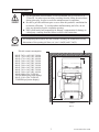
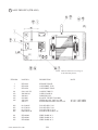
SPECIFICATIONS
Installation space
:
1,580 mm (W) X 2,460 mm (D)
(62.2 in. X 96.9 in.)
Height
: 2,230 mm (1045.0 in.)
Weight
: Approx.474 kg. (743.0 lbs.)
Power, maximum current
: 680 W 7.63 A (AC 110V 50 Hz AREA)
660 W 7.39 A (AC 110V 60 Hz AREA)
650 W 6.79 A (AC 120V 60 Hz AREA)
700 W 3.90 A (AC 220V 50 Hz AREA)
690 W 3.89 A (AC 220V 60 Hz AREA)
720 W 3.94 A (AC 230V 50 Hz AREA)
700 W 3.80 A (AC 230V 60 Hz AREA)
690 W 3.61 A (AC 240V 50 Hz AREA)
660 W 3.44 A (AC 240V 60 Hz AREA)
For TAIWAN (MITSUBISHI PROJECTION DISPLAY TYPE)
Power, current
: 680 W 8.00 A (MAX.)
300 W 3.40 A (MIN.)
For TAIWAN (TOSHIBA PROJECTION DISPLAY TYPE)
Power, current
: 705 W 8.10 A (MAX.)
310 W 3.60 A (MIN.)
MONITOR
: 50 TYPE PROJECTION DISPLAY
INTRODUCTION OF THE OWNER'S MANUAL
This Owner's Manual is intended to provide detailed descriptions together with all
the necessary information covering the general operation of electronic assemblies,
electromechanicals, servicing control, spare parts, etc. as regards the product,
EIGHTEEN WHEELER DELUXE.
This manual is intended for the owners, personnel and managers in charge of
operation of the product. Operate the product after carefully reading and sufficiently
understanding the instructions. If the product fails to function satisfactorily, nontechnical personnel should under no circumstances touch the internal system. Please
contact where the product was purchased from.
Use of this product is unlikely to cause physical injuries or damages to property. However,
where special attention is required this is indicated by a thick line, the word "IMPORTANT"
and its sign in this manual.
STOP
Indicates that mishandling the product by disregarding this display can cause the
product's intrinsic performance not to be obtained, resulting in malfunctioning.
IMPORTANT
SEGA ENTERPRISES, INC. (U.S.A.)/CUSTOMER SERVICE
45133 Industrial Drive, Fremont, California 94538, U.S.A.
Phone : (415) 701-6580
Fax : (415) 701-6594
DEFINITION OF LOCATION MAINTENANCE MAN AND SERVICEMAN
Non-technical personnel who do not have technical knowledge and expertise
should refrain from performing such work that this manual requires the location's
maintenance man or a serviceman to carry out, or work which is not explained in
this manual. Failing to comply with this instruction can cause a severe accident
such as electric shock.
Ensure that parts replacement, servicing & inspections, and troubleshooting are performed by the
location's maintenance man or the serviceman. It is instructed herein that particularly hazardous
work should be performed by the serviceman who has technical expertise and knowledge.
The location's maintenance man and serviceman are herein defined as follows:
"Location's Maintenance Man" :
Those who have experience in the maintenance of amusement equipment and vending machines,
etc., and also participate in the servicing and control of the equipment through such routine work
as equipment assembly and installation, servicing and inspections, replacement of units and
consumables, etc. within the Amusement Facilities and or locations under the management of the
Owner and Owner's Operators of the product.
Activities of Location's Maintenance Man :
Assembly & installation, servicing & inspections, and replacement of units & consumables as
regards amusement equipment, vending machines, etc.
Serviceman :
Those who participate in the designing, manufacturing, inspections and maintenance service of
the equipment at an amusement equipment manufacturer.
Those who have technical expertise equivalent to that of technical high school graduates as regards electricity, electronics and or mechanical engineering, and daily take part in the servicing &
control and repair of amusement equipment.
Serviceman's Activities :
Assembly & installation and repair & adjustments of electrical, electronic and mechanical parts of
amusement equipment and vending machines.
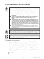
1. HANDLING PRECAUTIONS
When installing or inspecting the machine, be very careful of the following points and pay
attention to ensure that the player can enjoy the game safely.
Non-compliance with the following points or inappropriate handling running counter to the
cautionary matters herein stated can cause personal injury or damage to the machine.
Before performing work, be sure to turn power off. Performing the work
without turning power off can cause an electric shock or short circuit. In the
case work should be performed in the status of power on, this manual always
states to that effect.
To avoid electric shock or short circuit, do not plug in or unplug quickly.
To avoid electric shock, do not plug in or unplug with a wet hand.
Do not expose Power Cords and Earth Wires on the surface, (floor, passage,
etc.). If exposed, the Power Cords and Earth Wires are susceptible to damage.
Damaged cords and wires can cause electric shock or short circuit.
To avoid causing a fire or electric shock, do not put things on or damage
Power Cords.
When or after installing the product, do not unnecessarily pull the power cord.
If damaged, the power cord can cause a fire or electric shock.
In case the power cord is damaged, ask for replacement through where the
product was purchased from or the office herein stated. Using the cord as is
damaged can cause fire, electric shock or leakage.
Be sure to perform grounding appropriately. Inappropriate grounding can
cause an electric shock.
Be sure to use fuses meeting specified rating. Using fuses exceeding the
specified rating can cause a fire or electric shock.
Completely make connector connections for IC BD and others. Insufficient
insertion can cause an electric shock.
Specification changes, removal of equipment, conversion and/or addition, not
designated by SEGA are not permitted.
• Failure to observe this may cause a fire or an electric shock. Non-compliance
with this instruction can have a bad influence upon physical conditions of the
players or the lookers-on, or result in injury during play.
• SEGA shall not be held responsible for damage, compensation for damage to
a third party, caused by specification changes not designated by SEGA.
Be sure to perform periodic maintenance inspections herein stated.
STOP
IMPORTANT
For the IC board circuit inspections, only the logic tester is allowed. The use
of a multiple-purpose tester is not permitted, so be careful in this regard.
The Projector is employed for this machine. The Projector's screen is
susceptible to damage, therefore, be very careful when cleaning the screen.
For details, refer to PROJECTOR.
1
www.seuservice.com
2. PRECAUTIONS CONCERNING INSTALLATION
LOCATION
This product is an indoor game machine. Do not install it outside. Even indoors,
avoid installing in places mentioned below so as not to cause a fire, electric shock,
injury and or malfunctioning.
Places subject to rain or water leakage, or places subject to high humidity in
the proximity of an indoor swimming pool and or shower, etc.
Places subject to direct sunlight, or places subject to high temperatures in the
proximity of heating units, etc.
Places filled with inflammable gas or vicinity of highly inflammable/volatile
chemicals or hazardous matter.
Dusty places.
Sloped surfaces.
Places subject to any type of violent impact.
Vicinity of anti-disaster facilities such as fire exits and fire extinguishers.
The operating (ambient) temperature range is from 5° C to 40° C.
Only in the case a projector is employed, the temperature range is from 5° C
to 30° C.
LIMITATIONS OF USAGE REQUIREMENTS
Be sure to check the Electrical Specifications.
Ensure that this product is compatible with the location's power supply,
voltage and frequency requirements.
A plate describing Electrical Specifications is attached to the product.
Non-compliance with the Electrical Specifications can cause a fire and
electric shock.
This product requires the Breaker and Earth Mechanisms as part of the
location facilities. Using them in a manner not independent can cause a fire
and electric shock.
Ensure that the indoor wiring for the power supply is rated at 15A or higher
(AC single phase 100 ~ 120V area), and 7A or higher (AC 220 ~ 240V area).
Non-compliance with the Electrical Specifications can cause a fire and
electric shock.
Be sure to independently use the power supply equipped with the Earth
Leakage Breaker. Using a power supply without the Earth Leakage Breaker
can cause an outbreak of fire when earth leakage occurs.
Putting many loads on one electrical outlet can cause generation of heat and a
fire resulting from overload.
When using an extension cord, ensure that the cord is rated at 15A or higher
(AC 100 ~ 120V area) and 7A or higher (AC 220 ~ 240V area). Using a cord
rated lower than the specified rating can cause a fire and electric shock.
www.seuservice.com
2
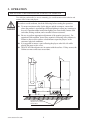
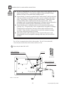
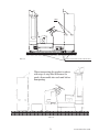
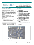
OPERATION AREA
For the operation of this machine, secure a minimum area of 2.905m (W) X
2.56m (D). In order to prevent injury resulting from the falling down accident
during game play, be sure to secure the minimum area for operation.
Be sure to provide sufficient space so as to allow this product's ventilation fan
to function efficiently. To avoid machine malfunctioning and a fire, do not
place any obstacles near the ventilation opening.
SEGA shall not be held responsible for damage, compensation for damage to
a third party, resulting from the failure to observe this instruction.
STOP
For transporting the machine into the location's building, the minimum necessary
dimensions of the opening (of doors, etc.) are 1.6m(W) and 1.7m(H).
IMPORTANT
Electric current consumption
MAX. 7.63 A (AC 110V 50 Hz)
MAX. 7.39 A (AC 110V 60 Hz)
MAX. 6.79 A (AC 120V 60 Hz)
MAX. 3.90 A (AC 220V 50 Hz)
MAX. 3.89 A (AC 220V 60 Hz)
MAX. 3.94 A (AC 230V 50 Hz)
MAX. 3.80 A (AC 230V 60 Hz)
MAX. 3.61 A (AC 240V 50 Hz)
MAX. 3.44 A (AC 240V 60 Hz)
MAX. 8.00 A (For TAIWAN,
MITSUBISHI projection display)
MAX. 8.10 A (For TAIWAN,
TOSHIBA projection display)
2.56m
10cm
2.905m
FIG. 2
3
www.seuservice.com
3. OPERATION
PRECAUTIONS TO BE HEEDED BEFORE STARTING THE OPERATION
To avoid injury and trouble, be sure to constantly give careful attention to the behavior and
manner of the visitors and players.
In order to avoid accidents, check the following before starting the operation:
To ensure maximum safety for the players and the customers, ensure that
where the product is operated has sufficient lighting to allow any warnings to
be read. Operation under insufficient lighting can cause bodily contact with
each other, hitting accident, and or trouble between customers.
Be sure to perform appropriate adjustment of the monitor (projector). For
operation of this machine, do not leave monitor's flickering or deviation as is.
Failure to observe this can have a bad influence upon the players' or the
customers' physical conditions.
It is suggested to ensure a space allowing the players who feel sick while
playing the game to take a rest.
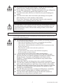
Check if all of the adjusters are in contact with the surface. If they are not, the
Cabinet can move and cause an accident.
Ensure that all of the
Adjusters are in contact
with the floor.
www.seuservice.com
4
Do not put any heavy item on this product. Placing any heavy item on the
product can cause a falling down accident or parts damage.
Do not climb on the product. Climbing on the product can cause falling down
accidents. To check the top portion of the product, use a step.
To avoid electric shock, check to see if door & cover parts are damaged or
omitted.
To avoid electric shock, short circuit and or parts damage, do not put the
following items on or in the periphery of the product.
Flower vases, flowerpots, cups, water tanks, cosmetics, and receptacles/
containers/vessels containing chemicals and water.
To avoid injury, be sure to provide sufficient space by considering the potentially
crowded situation at the installation location. Insufficient installation space can
cause making bodily contact with each other, hitting accidents, and or trouble
between customers.
PRECAUTIONS TO BE HEEDED DURING OPERATION (PAYING ATTENTION TO CUSTOMERS)
To avoid injury and trouble, be sure to constantly give careful attention to the behavior and
manner of the visitors and players.
To avoid injury and accidents, those who fall under the following categories
are not allowed to play the game.
• Those who need assistance such as the use of an apparatus when walking.
• Those who have high blood pressure or a heart problem.
• Those who have experienced muscle convulsion or loss of consciousness when
playing video game, etc.
• Those who have a trouble in the neck and or spinal cord.
• Intoxicated persons.
• Pregnant women or those who are in the likelihood of pregnancy.
• Persons susceptible to motion sickness.
• Persons whose act runs counter to the product's warning displays.
A player who has never been adversely affected by light stimulus might
experience dizziness or headache depending on his physical condition when
playing the game. Especially, small children can be subject to those
conditions. Caution guardians of small children to keep watch on their
children during play.
Instruct those who feel sick during play to have a medical examination.
To avoid injury resulting from falling down and electric shock due to spilled
drinks, instruct the player not to place heavy items or drinks on the product.
To avoid electric shock and short circuit, do not allow customers to put hands
and fingers or extraneous matter in the openings of the product or small
openings in or around the doors.
To avoid falling down and injury resulting from falling down, immediately
stop the customer's leaning against or climbing on the product, etc.
To avoid electric shock and short circuit, do not allow the customers to
unplug the power plug without a justifiable reason.
5
www.seuservice.com
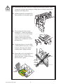
Immediately stop such violent acts as hitting and kicking the product. Such
violent acts can cause parts damage or falling down, resulting in injury due to
fragments and falling down.
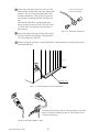
Children should be accompanied by
their guardians for playing the game.
The steering wheel has reaction
mechanism. Caution the guardians
of children so as not to insert hands
or arms in between the spokes.
Failure to observe this can cause
injury due to a sudden move of the
steering wheel.
Caution the player so as not to hold
a child in his/her lap to play. Failure
to observe this may cause injuries
resulting from a falling accident.
Instruct those who wear high-heel or
thick-sole shoes to refrain from
playing the game. Failure to observe
this can cause a sprain.
www.seuservice.com
6
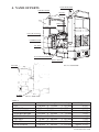
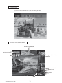
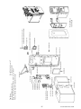
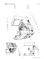
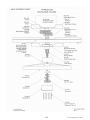
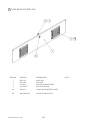
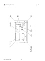
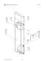
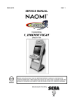
4. NAME OF PARTS
MAIN BILLBOARD
SUB BILLBOARD
PILLAR L
PTV
SHIFT LEVER
STEERING HANDLE
COIN CHUTE DOOR
CASHBOX DOOR
PTV BASE
ACCELERATOR & BRAKE
MAIN CABINET
FIG. 4 a OVERVIEW
PILLAR R
AC UNIT
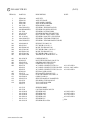
FIG. 4 b SIDE VIEW
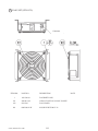
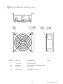
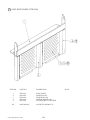
TABLE 4
PTV
PTV BASE
MAIN CABINET
MAIN BILLBOARD
SUB BILLBOARD
PILLAR R
PILLAR L
When assembled
Width
1,140 mm
1,165 mm
1,580 mm
1,252 mm
1,145 mm
170 mm
170 mm
1,580 mm
X
Length
X 554 mm
X 644 mm
X 1,880 mm
X 492 mm
X 335 mm
X 400 mm
X 400 mm
X ,460 mm
7
X
X
X
X
X
X
X
X
X
Height
1,670 mm
387 mm
1,410 mm
330 mm
260 mm
1,503 mm
1,503 mm
2,230 mm
Weight
110 kg
24 kg
291 kg
16 kg
9 kg
12 kg
12 kg
Approx. 479 kg
www.seuservice.com
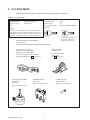
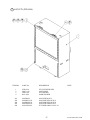
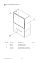
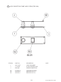
5. ACCESSORIES
When transporting the machine, make sure that the following parts are supplied.
TABLE 5 ACCESSORIES
DESCRIPTION
Part No. (Qty.)
Note
KEY MASTER
220-5576 (2)
For opening/closing
the doors
OWNERS MANUAL
420-6545-01 (1)
Figures
KEY
(2)
For the CASHBOX DOOR
If Part No. has no description, the Number has not been
registered or can not be registered. Such a part may not
be obtainable even if the customer desires to purchase it.
Therefore, ensure that the part is in safekeeping with you.
SERVICE MANUAL NAOMI ENG
420-6455-01 (1)
INSTRUCTION MANUAL FOR THE GAME BOARD
AC Cable (Power Cord)
600-6729 (1) AC 110V AREA
600-6695 (1) AC 120V AREA
600-6618 (1) AC 220 ~ 240V AREA
Used for installation, see 5 of Section 6.
VOL CONT B-5K OHM
220-5373
(1)
220-5484
Spare, see Section 10, 12.
www.seuservice.com
The Keys are inside the Coin
Chute Door at the time of
shipment from the factory.
CORD CLAMP
280-5009-01 (1)
Used for securing the
power cord.
see 5 of Section 6.
SW MICRO TYPE
509-5636 (1)
Spare, refer to Section 11.
8
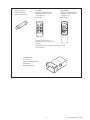
LAMP 14V 3.8W
390-6677-038 (1)
Spare, refer to Section 15.
FUSE 6.3A 125V
514-5086-6300 (1)
Spare, see Section 17.
TOSHIBA
Remote Controller used for
adjustment of the projector.
See Section 14.
200-5536(1)
TEST
MODE
WRITING
R
G
B
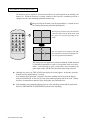
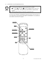
MITSUBISHI
Remote Controller used for
adjustment of the projector.
See Section 14.
200-5532(1)
P
POWER
SET
R / B
POSITION
R / G / B
PIC-ADJ
TEST
1
ADJUST
RESET
ENTER
8
9
10
R-MUTE G-MUTE B-MUTE
-- PICTURE +
SELECT
MITSUBISHI
One of the above 2 types of
Remote Controllers is used for the
Projector.
The Remote Controller is attached to the Projector at the
time of shipment.
NA
CARTON BOX
601-10532 (1)
Used for transporting the
Game Board.
Refer to Next Page.
OM
I
K
EC
H
C
E
D
SI
I
OM
NA
9
www.seuservice.com
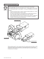
HOW TO USE THE CARTON BOX
When requesting for the replacement/repair of this product's Game Board
(NAOMI BOARD), follow the instructions below. Transporting the Game Board
in an undesignated status is unacceptable. An erroneous handling can cause parts
damage.
• Put the Game Board in the Carton Box together with the Shield Case. Do not
unnecessarily disassemble nor remove parts.
• By paying careful attention to the following Figure and the direction shown
by on-Carton-Box printing, put the Shield Case in the Carton Box.
• When putting the Shield Case in the Carton Box, do not remove Leg Brackets.
• The projected portions of the packing material is intended for cushioning.
Therefore, do not bend the projected portions.
STOP
IMPORTANT
"CHECK SIDE" Display
NA
OM
I
H
C
K
EC
E
D
SI
I
OM
NA
NA
OM
I
K
EC
H
C
E
D
SI
NA
OM
I
FILTER BOARD
Projected portions of
the packing material.
Fold the packing material in the sequential order of the numbers shown in the Figure, enfold
the Shield Case and put it in the Carton Box. Positioning the Shield Case upside down or
packing in the manner different from what is shown in this Figure can cause the Game Board
and other parts to be damaged.
www.seuservice.com
10
6. ASSEMBLING AND INSTALLATION
Perform assembly work by following the procedure herein stated. Failing to
comply with the instructions can cause electric shock hazard.
Perform assembling as per this manual. Since this is a complex machine,
erroneous assembling can cause an electric shock, machine damage and or not
functioning as per specified performance.
When assembling, be sure to use plural persons. Depending on the assembly
work, there are some cases in which working by one person alone can cause
personal injury or parts damage.
Ensure that connectors are accurately connected. Incomplete connections can
cause electric shock hazard.
Be careful so as not to damage wirings. Damaged wiring can cause electric
shock and short circuit hazards.
Do not carelessly push the PTV. Pushing the PTV carelessly can cause the
PTV to fall down.
This work should be performed by the Location's Maintenance Man or
Serviceman. Performing work by non-technical personnel can cause a severe
accident such as electric shock. Failing to comply with this instruction can
cause a severe accident such as electric shock to the player during operation.
Provide sufficient space so that assembling can be performed. Performing
work in places with narrow space or low ceiling may cause an accident and
assembly work to be difficult.
When handling plastic parts, use care. Do not give a shock or apply excessive
load to the fluorescent lamps and plastic parts. Failure to observe this can
cause parts damage, resulting in injury due to fragments, cracks and broken
pieces.
To perform work safely and securely, be sure to prepare a step which is in a
secure and stable condition. Performing work without using the step can
cause violent falling down accidents.
The PTV screen is susceptible to damage. Use care when handling the PTV.
If damaged, repair can not be performed.
11
www.seuservice.com
When carrying out the assembly work, follow the procedure in the following 7-item sequence:
1
2
3
4
5
6
7
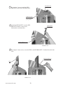
ASSEMBLING THE PTV
INSTALLING THE MAIN BILLBOARD, PILLAR L, AND PILLAR R
INSTALLING THE PTV
SECURING IN PLACE (ADJUSTER ADJUSTMENT)
POWER SUPPLY, AND EARTH CONNECTION
TURNING POWER ON
ASSEMBLY CHECK
When assembling, make sure that tools such as a Phillips type screwdriver, wrench (for M16
hexagon bolt), socket wrench (M6, M8 hexagon bolt), ratchet handle, and the master key are
available.
Phillips type screwdriver
24mm
WRENCH (for M16 hexagon bolt)
SOCKET WRENCH,(for M6,M8 hexagon bolt)
RATCHET HANDLE
www.seuservice.com
12
KEY MASTER
1
ASSEMBLING THE PTV
1 Secure the 2 Mask Holders to the PTV
ceiling with the 2 Flat Head screws for
each.
FLAT HEAD SCREW (2 each)
M4 X 12
2 Secure the Mask to the PTV with a total
of 6 screws.
MASK HOLDER
PTV
TRUSS SCREW (2)
M5 X 25,chrome,
flat washer used.
MASK
FIG. 6. 1 a
SCREW (4)black
M5 X 20,w/flat & spring washers
3 Secure the 2 PTV Holders to the
PTV front with the 2 screws for
each.
FIG. 6. 1 b
SCREW(2 each)M5 X 16,w/flat & spring washers
PTV HOLDER
13
www.seuservice.com
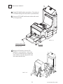
2
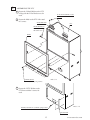
INSTALLING THE MAIN BILLBOARD, PILLAR L, AND PILLAR R
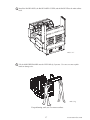
1 Take out the 7 truss screws to
remove the BACK PANEL
COVER from the back of main
cabinet.
2 Take out the 2 hexagon bolts to
remove the BACK PANEL from
the back of main cabinet.
3 Take out the 2 truss screws, unlock
the lock, and remove the BACK
LID.
FIG. 6. 2 a
TRUSS SCREW (7) M4 X 20,chrome,flat washer used.
BACK PANEL COVER
HEXAGON BOLT (2)
M6 X 40,w/spring washer,
flat washer used.
BACK PANEL
UNLOCK.
BACK LID
www.seuservice.com
FIG. 6. 2 b
TRUSS SCREW (2)
M4 X 25,black
14
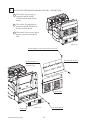
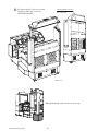
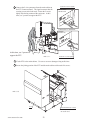
4 Install the PILLAR L and PILLAR R to the left & right sides of main cabinet and secure with
the 6 hexagon bolts for each. Fasten the 2 bolts from inside the BACK LID.
The PILLAR R has wiring. Check with the connector portion. Install the PILLAR L to the left
side and the PILLAR R to the right-hand side of main cabinet when facing from the PTV
screen. Fasten the bolts while another person supporting the PILLAR.
HEXAGON BOLT (6 each)
M6 X 40,w/spring washer,
flat washer used.
FIG. 6. 2 c
FIG. 6. 2 d
15
www.seuservice.com
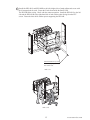
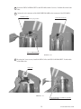
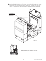
5 To secure the PILLAR, install the L-shaped Bracket from the seat side. Secure the PILLAR
CABI BRACKET UPPER with the 3 truss screws and the PILLAR CABI BRACKET LOWER
with the 4 truss screws. Perform this on the both sides.
PILLAR CABI BRACKET UPPER
TRUSS SCREW (3 each)
M6 X 30,black
TRUSS SCREW (4 each)
M6 X 30,black
FIG. 6. 2 e
PILLAR CABI BRACKET LOWER
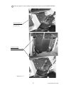
6 Connect the PILLAR R's wire connector to the main cabinet's connector.
Connect the Connector.
PHOTO 6. 2 a
www.seuservice.com
16
7 Install the BACK PANEL, the BACK PANEL COVER, and the BACK LID to the main cabinet
back.
FIG. 6. 2 f
8 Lift the MAIN BILLBOARD onto the 2 PILLARs by 2 persons. Use care so as not to pinch
hands or damage wire.
FIG. 6. 2 g
For performing work, use 2 or more workers.
17
www.seuservice.com
9 By using a total of 4 truss screws from
TRUSS SCREW (4 in total)
M5 X 50,black,
flat washer used.
inside the 2 PILLARs, secure the
MAIN BILLBOARD.
FIG. 6. 2 h
When performing work, be sure to use a step.
www.seuservice.com
18
10 Secure the END CAP BRACKET to the PILLAR with the 2 screws. Perform this on the both
sides.
11 Connect the wire connector of the MAIN BILLBOARD to the connector of the PILLAR R.
SCREW (2 each)
M4 X 20,black,w/flat & spring washers
Connect the Connector.
END CAP BRACKET
PHOTO 6. 2 b
12 By using the 3 truss screws, install the END CAP to the END CAP BRACKET. Perform this
on the both sides.
END CAP
PHOTO 6. 2 c
TRUSS SCREW (3 eachM4 X 12,chrome,
flat washer used.
19
www.seuservice.com
PIPE BRACKET
13 By using the 2 screws, install the PIPE
BRACKET to the END CAP BRACKET.
SCREW (2 each)
M4 X 20,w/flat &
spring washers
14 Install the PIPE SAFETY on to the PIPE
PIPE SAFETY
BRACKET with the 2 truss screws.
Perform this on the both sides.
TRUSS SCREW (2 each)
M4 X 16,black
PHOTO 6. 2 d
15 By using the 4 truss screws, secure the PIPE to the PIPE BRACKET. Perform this on the both
sides.
TRUSS SCREW (4)
M4 X 12,chrome
PIPE
PHOTO 6. 2 e
www.seuservice.com
20
3
INSTALLING THE PTV
1 Fit the PTV BASE and the main cabinet. The surface of
PTV BASE fitting to the main cabinet is predetermined.
2 Secure the PTV BASE and the main cabinet with a total
of 6 hexagon bolts.
FIG. 6. 3 a
HEXAGON BOLT (4)
M8 X 30,w/spring washer,
flat washer used.
PTV BASE
3 Mount the PTV halfway onto the PTV
BASE by 3 or more persons. At this time,
be sure to use another person to support the
main cabinet or cause the adjusters to come
into contact with the floor.
FIG. 6. 3 b
21
www.seuservice.com
4 Connect the 2 wire connectors from the main cabinet to
the PTV Connector Panel. The signal connector has the
securing screws at the both ends. Fasten the 2 screws
tightly after having connected the connector. At this
time, use 3 persons to support the PTV.
Fasten the 2 screws tightly.
MITSUBISHI
PROJECTOR
Connect the 2 Connectors.
TOSHIBA
PROJECTOR
At this time, use 3 persons to
support the PTV.
FIG. 6. 3 c
Fasten the 2 screws tightly.
5 Fit the PTV to the main cabinet. Use care so as not to damage wiring at this time.
6 Secure the joining portion of the PTV and the main cabinet with a total of 4 screws.
FIG. 6. 3 d
PTV
www.seuservice.com
TRUSS SCREW (4 in total)
M5 X 40,chrome,
flat washer used.
22
7 Install the SUB BILLBOARD to the PTV ceiling. Insert the SUB BILLBOARD to the 2 Mask
Holders on the PTV ceiling and secure with the 2 truss screws. To perform work safely and
securely, be sure to use a step. Do not step on the PTV or the main cabinet to perform work.
TRUSS SCREW (2)
M5 X 16,chrome,
flat washer used.
SUB BILLBOARD
FIG. 6. 3 e
When performing work, be sure to use a step.
23
www.seuservice.com
4
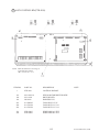
SECURING IN PLACE (ADJUSTER ADJUSTMENT)
Make sure that all of the adjusters are in contact with the floor. If they are not, the
cabinet can move and cause an accident.
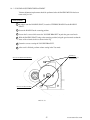
This product has 8 casters (4 for PTV BASE, 4 for MAIN CABINET) and 8 Adjusters (4 for
PTV BASE, 4 for MAIN CABINET). (FIG. 6. 4 a) When the installation position is determined, cause the adjusters to come into contact with the floor directly, make adjustments in a
manner so that the casters will be raised approximately 5mm. from the floor and make sure that
CASTER
the machine position is level.
1 Transport the product to the
installation position. Be sure to
provide adequate space allowing
the player to get on and off.
2 Have all of the Adjusters make
contact with the floor. Adjust the
Adjuster's height by using a
wrench so that the machine
position is kept level.
3 After making adjustment, fasten
the Adjuster Nut upward and
secure the height of Adjuster
(FIG. 6. 3 b).
ADJUSTER
FIG. 6. 4 a BOTTOM VIEW
ADJUSTER
CASTER
FASTEN UPWARD.
Approx.5mm
ADJUSTER
FIG. 6. 4 b ADJUSTER
2.56m
10cm
FIG. 6. 4 c
2.905m
FIG. 6. 4 d
Refer to this Fig. (Scale:1/100)
for the layout of the place of
installation.
www.seuservice.com
Be sure to provide space as shown between
the Air Vent and the wall surface.
24
5
POWER SUPPLY, AND EARTH CONNECTION
Be sure to independently use the power supply socket outlet equipped with an
Earth Leakage Breaker. Using a power supply without an Earth Leakage
Breaker can cause a fire when electric leakage occurs.
Ensure that the "accurately grounded indoor earth terminal" and the earth wire
cable are available (except in the case where a power cord plug with earth is
used). This product is equipped with the earth terminal. Connect the earth
terminal and the indoor earth terminal with the prepared cable. If the
grounding work is not performed appropriately, customers can be subjected to
an electric shock, and the product's functioning may not be stable.
Ensure that the power cord and earth wire are not exposed on the surface
(passage, etc.). If exposed, they can be caught and are susceptible to damage.
If damaged, the cord and wire can cause electric shock and short circuit
accidents. Ensure that the wiring position is not in the customer's passage
way or the wiring has protective covering.
After wiring power cord on the floor, be sure to protect the power cord.
Exposed power cord is susceptible to damage and causes an electric shock
accident.
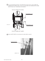
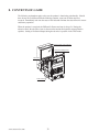
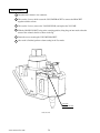
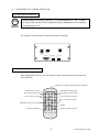
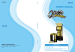
The AC Unit is mounted on the left side of the machine. The AC Unit has Main SW,
Circuit Protector and the Inlet which connects the Power Cord.
1 Ensure that the Main SW is OFF.
EARTH TERMINAL
Connect with the indoor earth terminal.
MAIN SW
Main SW off
CIRCUIT PROTECTOR
AC Cable (Power Cord)
FIG. 6. 5 a AC unit
INLET
25
www.seuservice.com
2 Connect one end of the earth wire to the AC Unit
Connect the Earth Wire
to the Earth Terminal.
earth terminal, and the other end to the indoor earth
terminal. The AC Unit earth terminal has a Bolt
and Nut combination. Take off the Nut, pass the
end of earth wire through the Bolt, and fasten the
Nut.
Note that the Earth Wire is incorporated in the
Power Cord for the Areas of AC 120V (USA) and
AC 220Å`240V, and therefore, this procedure is
not necessary.
FIG. 6. 5 b Earth Wire Connection
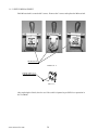
3 Firmly insert the power plug into the socket outlet.
Insert the opposite side of Power Cord plug to the
AC Unit's connector ("INLET").
4 Perform wiring for the Power Cord and Earth Wire. Install protective covering for the Power
Cord and Earth Wire.
Wiring Cover
FIG. 6. 5 c Connecting Power Cord and Earth Wire
In case the Power Plug is apt to come out of place, secure the
Power Cord to the periphery of the AC Unit with the Cord
Clamp (an accessory).
HOW TO USE THE CORD CLAMP
www.seuservice.com
26
6
TURNING POWER ON
Turn the AC Unit's main switch on to supply power. When power is turned on, the fluorescent
lamp inside the MAIN BILLBOARD lights up. The monitor displays NAOMI SYSTEM boot
up and then proceeds to the advertise mode. During this time, the initialization setting is
automatically performed. Do not touch the machine until the advertise mode is displayed on the
monitor after finishing the initialization setting. While initializing, the steering wheel turns left
& right and stops at the centering position. In the initialization setting, the values of V.R. inside
the control panel are corrected. Until the initialization is finished (the steering wheel stops
automatically), do not touch the steering wheel or play the game. If you do, the steering wheel
reaction during the game (reaction at the time of a course-out or crashing) can not be obtained
correctly. In case of an abnormal reaction during the game, turn the power on again from the
beginning and complete the initialization setting.
In this product, once the power is turned off, the data of inserted coins less than one credit and
BONUS ADDER is cleared. In the advertise mode, sound is emitted from the 2 speakers.
Sound is not emitted if set to NO SOUND OUTPUT in the test mode.
Image output on the monitor.
Fluorescent lamps are lit.
The steering wheel turns left & right.
Emits sounds.
27
www.seuservice.com
7
ASSEMBLING CHECK
In the TEST MODE, ascertain that the assembly has been made correctly and IC BD. is
satisfactory (refer to Section 9).
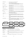
In the test mode, perform the following test:
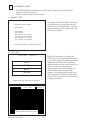
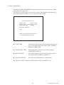
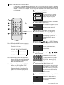
(1) MEMORY TEST
Selecting the desired RAM TEST item on the
test mode menu screen causes the on-board
memory to be tested automatically. The game
board is satisfactory if the display beside each
IC No. shows GOOD.
MEMORY TEST MODE
RAM TEST
IC29 GOOD
IC34 GOOD
IC16 GOOD IC18 GOOD
IC20 GOOD IC22 GOOD
IC9 GOOD IC10 GOOD
IC11 GOOD IC12 GOOD
PRESS TEST BUTTON TO CONTINUE
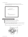
(2) C.R.T. TEST
C.R.T. TEST
PAGE 1/2
In the TEST mode menu, selecting C.R.T.
TEST allows the screen (on which the monitor
is tested) to be displayed. Although the monitor
adjustments have been made at the time of
shipment from the factory, color deviation, etc.,
may occur due to the effect caused by
geomagnetism, the location building's steel
frames and other game machines in the
periphery. By watching the test mode screen,
make judgment as to whether an adjustment is
needed. If it is necessary, adjust the monitor by
referring to Section 14.
RED
GREEN
BLUE
WHITE
PRESS TEST BUTTON TO CONTINUE
C.R.T. TEST
PAGE 2/2
PRESS TEST BUTTON TO EXIT
www.seuservice.com
28
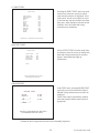
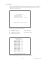
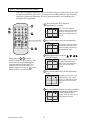
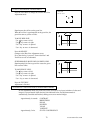
(3) INPUT TEST
Selecting the INPUT TEST on the test mode
menu screen causes the screen (on which
each switch is tested) to be displayed. Press
each switch. For the coin switch test, insert
a coin from the coin inlet with the coin chute
door open. If the display beside each switch
indicates "ON," the switch and wiring
connections are satisfactory.
INPUT TEST
COIN CHUTE #1
COIN CHUTE #2
SERVICE
TEST
START
VIEW
HORN
SHIFT [L]
SHIFT [H]
SHIFT [R]
HANDLE
ACCEL
BRAKE
OFF
OFF
OFF
OFF
OFF
OFF
OFF
OFF
OFF
OFF
XXH
XXH
XXH
PRESS TEST + SERVICE BUTTON TO EXIT
(4)OUTPUT TEST
Select OUTPUT TEST from the menu in the
test mode to cause the screen (on which each
lamp and wiring connections are tested) to
appear. Ensure that lamp light up
satisfactorily.
OUTPUT TEST
START LAMP
VIEW LAMP
HORN LAMP
ROLL LEFT
ROLL RIGHT
OFF
OFF
OFF
OFF
OFF
->EXIT
SELECT WITH SERVICE BUTTON
AND PRESS TEST BUTTON
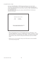
(5)SOUND TEST
In the TEST mode, selecting SOUND TEST
causes the screen (on which sound related
BD and wiring connections are tested) to be
displayed.
Check if the sound is satisfactorily emitted
from each speaker and the sound volume is
appropriate.
SOUND TEST
B.G.M
EFFECT
[_______]
ICS
[_______]
-> EXIT
0/ XX
0/ XX
0/ XX
SELECT WITH SERVICE BUTTON
AND PRESS TEST BUTTON
Perform the above inspections also at the time of monthly inspection.
29
www.seuservice.com
7. PRECAUTIONS TO BE HEEDED WHEN MOVING THE MACHINE
When moving the machine, be sure to unplug the power plug. Moving the
machine with the plug as is inserted can damage the power cord and cause fire
and electric shock hazards.
When moving the machine on the floor, retract the Adjusters and ensure that
Casters make contact with the floor. During transportation, pay careful
attention so that Casters do not tread power cords and earth wires. Damaging
the power cords can cause electric shock and short circuit hazards.
When lifting the cabinet, be sure to hold the grip portions or bottom part.
Lifting the cabinet by holding other portions can damage parts and installation
portions due to the empty weight of the cabinet, and cause personal injury.
When transporting the product in places with step-like differences in grade,
disassemble into each unit before transporting. Lifting up the product in an
attempt to cross the step-like differences in an as is assembled condition may
damage the unit's joining portions and cause a personal injury resulting from
damage.
When moving the PTV, do not push it from the rear side. Push it from
sideways. Pushing the PTV from the rear side can have the PTV fall down,
causing personal injury etc. In case the floor has slanted surfaces or step-like
differences, be sure to move the machine by 2 or more persons.
Do not insert the fork to places other than designated when using a Forklift to
transport the machine.
Failure to observe this could cause falling down and injury resulting from
falling down.
Do not push the plastic made parts. Failure to observe this may damage parts and
cause injury due to fragments resulting from damage.
STOP
IMPORTANT
When transporting the product in places with steps, disassemble into each unit
before transporting. Inclining the product in an as is assembled condition or
placing the cabinet in places with steps can damage the unit's joining portions.
To protect surface, do not directly apply a rope to the surfaces of product.
Use protective materials to the places the rope is applied to.
Do not push PTV from the back. Pushing the PTV
from the back can cause the PTV to fall down. Push
it from the side.
www.seuservice.com
30
GRIP
Have casters make contact with the floor.
FIG. 7 a
When transporting the product in places
with steps or step-like differences in
grade, disassemble into each unit before
transporting.
12345678901234567890123456789012123456789012345678901234567890121234567890123456789012345678
12345678901234567890123456789012123456789012345678901234567890121234567890123456789012345678
12345678901234567890123456789012123456789012345678901234567890121234567890123456789012345678
12345678901234567890123456789012123456789012345678901234567890121234567890123456789012345678
12345678901234567890123456789012123456789012345678901234567890121234567890123456789012345678
FIG. 7 b
31
www.seuservice.com
8. CONTENTS OF GAME
The following explanations apply to the case the product is functioning satisfactorily. Should
there be any moves different from the following contents, some sort of faults may have
occurred. Immediately look into the cause of the fault and eliminate the cause thereof to ensure
satisfactory operation.
When the product is energized, the Billboard's fluorescent lamp is always lit. During the
advertise mode, the advertise screen is shown on the monitor and sound is emitted from the
speakers. Setting to No Sound Output during the advertise is possible in the TEST mode.
Image output on the monitor.
Fluorescent lamps are lit.
Coin Inlet
Emits sounds.
www.seuservice.com
32
OUTLINE OF THE GAME
• This is a single, driving game in which the player competes with rivals by driving a Trailer
Truck to cross America.
• When coins are inserted to gain credits, the START button starts flashing. Press the START
button to proceed to the SELECTOR mode where you can select your truck and trailer. The
game starts upon selecting the truck and the trailer.
• Based on the setting made in the test mode, the number of coins inserted to obtain a credit
counts as one credit in this product. The number of credits necessary to start game and to
continue game can be set in the test mode.
• The game consists of the 4 kinds of stages and 3 kinds of parking stages (Bonus stages).
• When continued, game is played at the beginning of the latest stage where you result in game
over.
• If your score falls within the top 5, you can enter your name.
CONTENTS OF GAME
• Pass the checking point within a certain period of time and reach the goal, and you can clear
the stage.
• The game finishes when clearing all 4 stages.
• If you can reach the goal ahead of your rival trailers in each stage(the 1st through the 3rd),
you can play Parking game (Bonus game).
GAME OVER
• If you fail to pass the checking point within a certain period of time or fail to goal, game is
over.
• Getting behind the rival trailers at the checking point or failing on the Parking game does not
result in game over.
33
www.seuservice.com
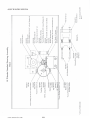
HORN AT THE ASSISTANT DRIVER'S SEAT
STEERING WHEEL
OPERATION
START BUTTON
VIEW CHANGE BUTTON
GEAR
BRAKE
ACCEL.
CONTROL PANEL and ACCEL. & BRAKE
HORN AT THE DRIVER'S SEAT
<STEERING WHEEL>
SELECTOR : Turn right or left to select an object.
GAME PLAY : Operate the Trailer Truck.
<HORN AT THE DRIVER'S SEAT>
SELECTOR : Decide
GAME PLAY : Blow the horn to signal the car ahead to move out of the way or to have it
increase the speed.
Have the trailer ahead increase the speed.
<ACCEL..>
SELECTOR : Decide
GAME PLAY : Increase your Trailer Truck speed.
<BRAKE>
SELECTOR : Void
GAME PLAY : Decrease your Trailer Truck speed, or stop it.
<GEAR>
SELECTOR : Void
GAME PLAY : 3-position, HI (High), LOW, R (Reverse)
<VIEW CHANGE>
SELECTOR : Void
GAME PLAY : Select either Driver's View or Bird View.
<START BUTTON>
The START button flashes when the number of coins that are worth one credit are inserted.
While flashing, press the START button to proceed to the SELECTOR.
It also flashes when one or more credit(s) remains after the game over.
<HORN AT THE ASSISTANT DRIVER'S SEAT>
SELECTOR : Decide
GAME PLAY : Signal the car ahead to move the way or to increase the speed.
Signal the trailer ahead to increase the speed.
This has the same effect with the horn at the driver's seat.
www.seuservice.com
34
SELECTOR
TRUCK SELECT
Select the truck from among ASPHALT COWBOY, STREAMLINE, HIGHWAY CAT,
LONG HORN, and NIHONMARU (not available for Korea version). Each truck's abilities in
SPEED, TORQUE, and TOUGHNESS differ.
TRAILER SELECT
When starting in the stages 2, 3, and 4, select the trailer for towing from the 2 trailers. The
weight, the length, and the transportation fee differ. The heavier the trailer, the more the difficulty.
35
www.seuservice.com
NAME ENTRY
If your score falls within the top 5, you can enter your name.
VIEWING THE GAME SCREEN
REARVIEW MIRROR
DESTINATION
TIME LIMIT
TRANSPORTAION
FEE
GEAR CHANGE
INDICATOR
GEAR
CONDITION
TACHOMETER
www.seuservice.com
36
<DESTINATION>
Name of the destination point.
<TIME LIMIT>
Indicates the player's playable time. Additional time will be added when passing the
CHECKPOINT and obtaining TIME BONUS.
<REARVIEW MIRROR>
Indicates the rear condition while DRIVER'S VEIW is being selected.
<TRANSPORTATION FEE>
Indicates the fee you receive when you reach the destination. If you give damage to the
trailer by hitting another car, etc., the fee will be reduced.
<TACHOMETER>
Indicates speed of rotation.
<GEAR CHANGE INDICATOR>
Indicates the gear condition (4 positions in total) with the lamp on the monitor.
<GEAR CONDITION>
Indicates the current gear condition. The three types of gears (REVERSE • LOW • HI) are
available.
37
www.seuservice.com
9. EXPLANATION OF TEST AND DATA DISPLAY
By operating the switch unit, periodically perform the tests and data check. When installing the
machine initially or collecting cash, or when the machine does not function correctly, perform
checking in accordance with the explanations given in this section.
The following shows tests and modes that should be utilized as applicable.
NAOMI GAME BOARD is used for the product. The system of this game board allows
another game to be played by replacing the ROM Board Case mounted on the NAOMI CASE.
As such, the Test Mode of this system consists of the System Test Mode for the system to
execute SELF-TEST, COIN ASSIGNMENTS, etc. used in common for the machines
employing the NAOMI BOARD, and the Game Test Mode for the specific product to execute
Input/Output test for the operation equipment, difficulty setting, etc. In this manual,
explanations regarding the System Test Mode cover the settings for this product only. For the
details of the System Test Mode, refer to NAOMI SERVICE MANUAL, an accessory.
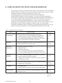
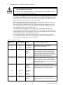
TABLE 9 EXPLANATION OF TEST MODE
ITEMS
DESCRIPTION
REFERENCE
SECTIONS
INSTALLATION
OF MACHINE
When the machine is installed, perform the following:
1. Check to ensure each is the standard setting at shipment.
2. Check each Input equipment in the INPUT TEST mode.
3. Check each Output equipment in the OUTPUT TEST mode.
4. Test on-IC-Board IC's in the SELF-TEST mode.
S E R V I C E
MANUAL
9-3E
9-3B
9-3C
MEMORY
This test is automatically executed by selecting RAM TEST, or
ROM BOARD TEST in the Menu mode.
S E R V I C E
MANUAL
PERIODIC
SERVICING
Periodically perform the following:
1. MEMORY TEST
2. Ascertain each setting.
3. To test each Input equipment in the INPUT TEST mode.
4. To test each Output equipment in the OUTPUT TEST mode.
S E R V I C E
MANUAL
CONTROL
SYSTEM
1. To check each Input equipment in the INPUT TEST mode.
2. Adjust or replace each Input equipment.
3. If the problem still remains unsolved, check each equipment's
mechanism movements.
MONITOR
In the Monitor Adjustment mode, check to see if Monitor (Projector) adjustments are appropriate.
IC BOARD
1. MEMORY TEST
2. In the SOUND TEST mode, check the sound related ROMs.
DATA CHECK
Check such data as game play time and histogram to adjust the
difficulty level, etc.
www.seuservice.com
38
S E R V I C
MANUAL
9-3E
9-3B
9-3C
S E R V I C
MANUAL
9-3B,F 10,11,12
S E R V I C
MANUAL
14
S E R V I C
MANUAL
9-3D
S E R V I C
MANUAL
9-3G
E
E
E
E
E
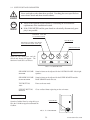
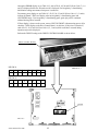
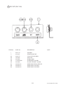
9 - 1 SWITCH UNIT AND COIN METER
Never touch places other than those specified. Touching places not specified can
cause electric shock and short circuit accidents.
STOP
IMPORTANT
Adjust to the optimum sound volume by considering the environmental
requirements of the installation location.
If the COIN METER and the game board are electrically disconnected, game
play is not possible.
SPEAKER VOLUME
For SUPER WOOFER
TEST BUTTON
SPEAKER VOLUMEFor SPEAKERS
at theCONTROL PANEL left & right.
SERVICE BUTTON
SWITCH UNIT
Open the coin chute door, and the
switch unit shown will appear. The
function of each SW is as follows:
FIG. 9. 1 a SWITCH UNIT
SPEAKER VOLUME:
SPEAKER
SPEAKER VOLUME:
Sound volume can be adjusted for the CONTROL PANEL left & right
speakers.
SUPER WOOFER
Sound volume can be adjusted for the SUPER WOOFER and the
BASE SHAKER under the seat.
TEST BUTTON:
Enters to the test mode.
TEST
SERVICE BUTTON:
Gives credits without registering on the coin meter.
SERVICE
COIN METER
COIN METER
Open the Cashbox Door by using the key to
have the Coin Meter appear underneath the
Cashbox.
FIG. 9. 1 b COIN METER
39
www.seuservice.com
9 - 2 SYSTEM TEST MODE
The contents of settings changed in the TEST mode are stored when the test
mode is finished from EXIT in the menu mode. If the power is turned off
before the TEST mode is finished, the contents of setting change become
ineffective.
Executing "BACKUP DATA CLEAR" in the SYSTEM TEST MODE does
not clear the BOOKKEEPING data in the GAME TEST mode.
Entering the TEST mode clears fractional number of coins less than one credit
and BONUS ADDER data.
Perform setting as per specified in this manual for operation. If setting not
specified is performed for operation, proper function of this product may not
be obtained.
STOP
IMPORTANT!
In the SYSTEM TEST MODE, IC BD functioning can be checked, the monitor adjusted, and
the coin setting performed.
Refer to NAOMI SERIVCE MANUAL for the details. Note that the setting of the following
items need to be performed in accordance with the instruction given.
CABINET TYPE
MONITOR TYPE
SERVICE TYPE
COIN CHUTE TYPE
www.seuservice.com
:
:
:
:
1 PLAYER(S)
HORIZONTAL
COMMON
COMMON
40
9- 3 GAME TEST MODE
A. GAME TEST MODE MENU (MAIN MENU)
18WHEELER TEST MENU
SYSTEM MENU
JAPAN VERSION
INPUT TEST
OUTPUT TEST
SOUND TEST
GAME ASSIGNMENTS
VOLUME SETTING
BOOKKEEPING
BACKUP DATA CLEAR
-> EXIT
RAM TEST
JVS TEST
SOUND TEST
C.R.T. TEST
SYSTEM ASSIGNMENTS
COIN ASSIGNMENTS
BOOKKEEPING
BACKUP DATA CLEAR
CLOCK SETTING
ROM BOARD TEST
-> GAME TEST MODE
[XXXXX XX XXXX---------------]
EXIT
SELECT WITH SERVICE BUTTON
AND PRESS TEST BUTTON
SELECT WITH SERVICE BUTTON
AND PRESS TEST BUTTON
SYSTEM TEST MODE MENU
GAME TEST MODE MENU
FIG. 9. 3 a MENU MODE
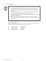
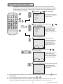
• Press the TEST button to indicate the SYSTEM TEST MODE MENU screen.
• Bring the arrow by pressing the SERVICE button and select the GAME TEST MODE.
Press the TEST button to indicate the GAME TEST MODE MENU screen.
• By pressing the SERVICE button, bring the arrow and select an item. Press the TEST button
to enter the test item.
• Select EXIT and press the TEST button to finish the GAME TEST MODE. The screen
returns to the SYSTEM TEST MODE MENU screen. Select EXIT in this mode and press
the TEST button to finish the SYSTEM TEST MODE. The screen returns to the game
mode.
41
www.seuservice.com
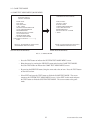
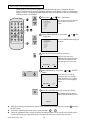
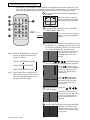
B. INPUT TEST
When the INPUT TEST is selected, the following screen is displayed on the monitor.
INPUT TEST
COIN CHUTE #1
COIN CHUTE #2
SERVICE
TEST
START
VIEW
HORN
SHIFT [L]
SHIFT [H]
SHIFT [R]
HANDLE
ACCEL
BRAKE
OFF
OFF
OFF
OFF
OFF
OFF
OFF
OFF
OFF
OFF
XXH
XXH
XXH
PRESS TEST + SERVICE BUTTON TO EXIT
• When pressing each switch, if the display next to the item changes to ON from OFF, the
switch and the wiring connection are satisfactory.
• To check COIN CHUTE #1 & #2, open the COIN CHUTE DOOR and insert coins.
• "HORN" is for the driver seat and the assistant driver seat. Because the same circuit is used
for HORN in the driver and the assistant driver seats, if the switch and the wiring connection
are satisfactory, pressing the HORN at either side changes the display to ON from OFF.
• For the steering wheel, the accelerator, and the brake, operate each input device and check to
see if the value changes in accordance with operation.
Items to be checked:
Each switch (COIN/ SERVICE/ TEST/ START/ VIEW CHANGE/ HORN/ SHIFT <H L R>)
Each volume (STEERING WHEEL/ ACCELERATOR/ BRAKE)
• Press the SERVICE and TEST buttons simultaneously to return to the MENU screen.
www.seuservice.com
42
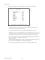
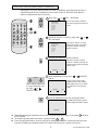
C. OUTPUT TEST
Selecting the OUTPUT TEST displays the following screen on the monitor. The condition of
each lamp and motor can be checked.
OUTPUT TEST
START LAMP
VIEW LAMP
HORN LAMP
ROLL LEFT
ROLL RIGHT
OFF
OFF
OFF
OFF
OFF
->EXIT
SELECT WITH SERVICE BUTTON
AND PRESS TEST BUTTON
• Bring the arrow to the desired item and press the TEST button. The display next to the item
changes to ON from OFF, the lamp lights up, and the motor functions.
LAMP item
ROLL LEFT
: If the lamp lights up, operation is satisfactory.
: If the motor moves so as to turn the steering wheel counterclockwise,
operation is satisfactory.
ROLL RIGHT : If the motor moves so as to turn the steering wheel clockwise,
operation is satisfactory.
• Bring the arrow to EXIT and press the TEST button to return to the MENU screen.
43
www.seuservice.com
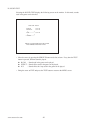
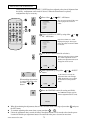
D. SOUND TEST
Selecting the SOUND TEST displays the following screen on the monitor. In this mode, sounds
used in the game can be checked.
SOUND TEST
B.G.M
0/ X X
EFFECT
0/ X X
[_______]
ICS
0/ X X
[_______]
-> EXIT
SELECT WITH SERVICE BUTTON
AND PRESS TEST BUTTON
• Move the arrow by pressing the SERVICE button and select an item. Every time the TEST
button is pressed, different sound is played.
B.G.M. : Sound used in the game can be played.
EFFECT : Sound effects used in the game can be played.
ICS
: Sound effects in a loop used in the game can be played.
• Bring the arrow to EXIT and press the TEST button to return to the MENU screen.
www.seuservice.com
44
E. GAME ASSIGNMENTS
Selecting the GAME ASSIGNMENTS displays the following screen on the monitor. Setting
for the game can be performed.
The contents of setting changes will be effective when the TEST MODE is finished properly.
If the setting changes are made, be sure to exit from the TEST MODE.
GAME ASSIGNMENTS
START TIME
[VERY EASY]
CHECK POINT TIME [VERY EASY]
MOTOR POWER
[LIGHT]
DEFAULT SETTING
-> EXIT
SELECT WITH SERVICE BUTTON
AND PRESS TEST BUTTON
START TIME
: Time limit given to the player at the beginning of the stage can
be set. Select from among VERY EASY, EASY, NORMAL,
HARD, and VERY HARD.
CHECK POINT TIME
: The additional time given to the player when passing the
CHECK POINT can be set.
MOTOR POWER
: The feedback stiffness of the steering wheel can be selected
from among LIGHT, NORMAL, and HEAVY.
DEFAULT SETTING
: This makes each setting return to its default setting.
Bring the arrow to EXIT and press the TEST button to return to the MENU screen.
45
www.seuservice.com
F. VOLUME SETTING
Selecting the VOLUME SETTING displays the following screen on the monitor.
The volume detecting the steering wheel operation can manually be set. The value can be
stored when exiting from the item.
VOLUME SETTING
HANDLE SETTING
SET CENTER
[LOCK] 00H
-> EXIT
SELECT WITH SERVICE BUTTON
AND PRESS TEST BUTTON
SETTING THE STEERING WHEEL VOLUME
1 Press the SERVICE button to bring the arrow to SET CENTER.
2 "SET CENTER [LOCK]" display changes to "SET CENTER [SET]."
3 Bring the steering wheel to the centering position manually.
4 Press the TEST button. The Volume value obtained at this time is stored as the steering wheel's
centering value, and "SET CENTER [LOCK]" is displayed.
If the value does not fall within 80+/5H at this time, perform volume adjustment by referring to
10-2.
Bring the arrow to EXIT and press the TEST button to return to the MENU screen.
www.seuservice.com
46
G. BOOKKEEPING
Selecting the BOOKKEEPING displays the data of operating status in 2 pages. Press the TEST
button to proceed to the next screen. When the TEST button is pressed in the 2/2 PAGE, the
screen returns to the MENU mode.
BOOKKEEPING 1/2
NUMBER OF GAMES
NUMBER OF CONTINUE
AVERAGE PLAY TIME
0
0
00M00S
PRESS TEST BUTTON TO CONTINUE
PAGE 1/2 displays the data of operating status.
NUMBER OF GAMES
:
Total number of plays.
NUMBER OF CONTINUE
:
Total number of continue.
AVERAGE PLAY TIME
BOOKKEEPING 2/2
TIME HISTOGRAM
00M00S - 00M29S ------- 0
00M30S - 00M59S ------- 0
01M00S - 01M29S ------- 0
01M30S - 01M59S ------- 0
02M00S - 02M29S ------- 0
02M30S - 02M59S ------- 0
03M00S - 03M29S ------- 0
03M30S - 03M59S ------- 0
04M00S - 04M29S ------- 0
04M30S - 04M59S ------- 0
05M00S - 05M29S ------- 0
05M30S - 05M59S ------- 0
06M00S - 06M29S ------- 0
06M30S - 06M59S ------- 0
OVER
07M00S ------- 0
PRESS TEST BUTTON TO EXIT
PAGE 2/2 displays Histogram of Number of Play as against Play Time.
47
www.seuservice.com
H. BACKUP DATA CLEAR
Selecting the BACKUP DATA CLEAR displays the following screen on the monitor.
The contents of BOOKKEEPING in the GAME TEST MODE and the ranking data can be
cleared. Note that this operation does not affect the contents of GAME ASSIGNMENTS and
the VOLUME SETTING.
The COIN/CREDIT related data can be cleared in the BACKUP DATA CLEAR in the
SYSTEM TEST MODE.
BACKUP DATA CLEAR
YES
-> NO
(CLEAR)
(CANCEL)
SELECT WITH SERVICE BUTTON
AND PRESS TEST BUTTON
• When clearing, bring the arrow to "YES (CLEAR)" and press the TEST button. "YES
(CLEAR) COMPLETED" is displayed, "COMPLETED" is flashing, and the data is cleared.
When the data has been cleared, the display stops flashing. After the data has been cleared,
bring the arrow to "NO (CANCEL)" and press the TEST button to return to the MENU
screen.
• Bring the arrow to "NO (CANCEL)" and press the TEST button to return to the MENU
screen without clearing the data.
www.seuservice.com
48
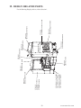
10. CONTROL PANEL (HANDLE MECHA)
Before starting to work, ensure that the Power SW is OFF. Failure to observe
this can cause electric shock or short circuit.
Use care so as not to damage wirings. Damaged wiring can cause electric
shock or short circuit.
Do not touch undesignated places. Touching places not designated can cause
electric shock or short circuit.
This work should be performed by the Location's Maintenance Man or
Serviceman. Performing work by non-technical personnel can cause electric
shock hazard.
Do not insert hand into the mechanism so as not to cause hand and fingers
pinched in. Failure to observe this can cause a serious injury such as a
fracture.
When performing work such as parts replacement other than those specified
in this manual, be sure to contact where you purchased the product from and
confirm the work procedures and obtain precautions prior to performing work.
Inappropriate parts replacement and/or installing with erroneous adjustment
can cause an overload or the parts to come into contact, resulting in an electric
shock, a short circuit, and a fire.
Use care when removing the HANDLE MECHA so as not to hurt the back.
Dropping the HANDLE MECHA on your foot can cause a fracture. Be very
careful of this point.
When putting the HANDLE MECHA, do not make the gear or the sensor portion
face down. Failure to observe this may damage the parts due to its own weight.
STOP
Be sure to perform Volume value setting in the Volume Setting in the Test Mode
after replacing or adjusting the Volume.
IMPORTANT
10- 1 REMOVING THE HANDLE MECHA
In cases the Steering operability is poor and the adjustment of VOLUME SETTING in the
TEST mode is ineffective, the causes may be the Volume Gear's mesh failure and or Volume
malfunctioning. By using the following procedure, adjust Volume gear mesh, or replace the
Volume. In this product, when the Steering Wheel is moved fully left/right, if the Volume shaft
is rotating within the movable range, the Volume is not feared to be damaged. Secure the
Volume in the manner the Volume shaft is oriented as shown and the gears are appropriately
engaged when the steering wheel is in the centering position allowing the car to go straight
forward.
In order to perform V.R. adjustment or replacement, remove the HANDLE MECHA as per the
following procedure.
1 Turn power off.
49
www.seuservice.com
2 Take out the 4 truss screws at the center of the steering wheel to remove the FRAME HORN
BUTTON and the CAP HORN BUTTON. A small part (PIN HORN BUTTON) is attached to
the CAP HORN BUTTON. Be sure to keep it.
3 Pull out the ROD HORN BUTTON.
4 Remove the SPRING and the CUSHION L.
5 Take out the hexagon nut.
6 Remove the WASHER HANDLE SHAFT.
7 Pull the STEERING HANDLE out of the HANDLE SHAFT. The HANDLE and the SHAFT
are nesting of gear-shape splines hole and the shaft. Be sure to pull the STEERING HANDLE
vertically so as not to damage the shaft.
8 Remove the COLOR HANDLE SHAFT.
TRUSS SCREW (4)
M4 X 25,chrome
FRAME HORN BUTTON
PIN HORN BUTTON
CUSHION U
SPRING
CUSHION L
CAP HORN BUTTON
WASHER HANDLE SHAFT
ROD HORN BUTTON
STEERING HANDLE
HEXAGON NUT (1)
M16
COLOR STEERING HUB
COLOR HANDLE SHAFT
FIG. 10. 1 a
www.seuservice.com
50
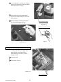
9 Take out the 4 screws, disconnect a connector, and remove the HORN BUTTON at the assistant
driver's seat. (See sec. 15)
10 Take out the 11 screws to remove the CONTROL PANEL COVER. Wiring connection is
inside the CONTROL PANEL COVER. Use care so as not to damage wiring. The CONTROL
PANEL COVER is made of plastic. Erroneous handling may damage the part.
11 Disconnect the 2 connectors inside the CONTROL PANEL COVER, and remove the
CONTROL PANEL COVER.
HORN BUTTON
TRUSS SCREW (11)
M4 X 16,black,
flat washer used.
CONTROL PANEL COVER
PHOTO 10. 1 a
12 Disconnect the HANDLE
MECHA's 2 wire connectors.
13 Take out a screw to remove the
earth wire.
Disconnect the connector.
PHOTO 10. 1 b
SCREW (1)M4 X 12,w/flat & spring washers
FIG. 10. 1 b
51
www.seuservice.com
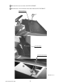
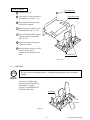
14 Take out the 4 screws to remove the LID TOP FRONT.
15 Disconnect the 2 wire connectors of the motor inside the LID TOP FRONT.
TRUSS SCREW (4)
M4 X 30,black
LID TOP FRONT
Disconnect the connector.
11
PHOTO 10. 1 c
www.seuservice.com
52
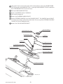
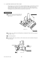
16 Take out a total of 6 screws and the 2 hexagon bolts which secure the HANDLE MECHA.
HOXAGON BOLT (2)
M6 X 25,w/spring washer,
flat washer used.
SCREW (6 in total)
M5 X 16,w/flat & spring washers
PHOTO 10. 1 d
53
www.seuservice.com
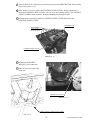
17 Remove the HANDLE MECHA.
Use care when performing work.
PHOTO 10. 1 e
18 When putting the HANDLE MECHA, be sure to have the gear and the sensor portions face
upper. Failure to observe this may damage the parts due to its own weight.
FIG. 10. 1 c
www.seuservice.com
54
10 - 2 VOLUME ADJUSTMENT/REPLACEMENT
Volume adjustment/replacement should be performed after the HANDLE MECHA has been
removed as per 10-1.
ADJUSTMENT
1 In order to turn the HANDLE SHAFT, insert the STEERING HANDLE to the HANDLE
SHAFT.
2 Secure the HANDLE at the centering position.
3 Loosen the 2 screws which secure the VOLUME BRACKET to push the gear out of mesh.
4 With the HANDLE SHAFT being at the centering position, bring the gear into mesh so that the
status of the volume's shaft is as shown in the Fig.
5 Fasten the screws securing the VOLUME BRACKET.
6 After work is finished, perform volume setting in the Test mode.
SCREW (2)
M4 X 14,w/flat &
spring washers
"D"CUT FACE(HANDLE SHAFT)
"D"CUT FACE(VOLUME)
FIG. 10. 2 a
55
www.seuservice.com
REPLACEMENT
1 Disconnect the volume's wire connector.
2 Take out the 2 screws which secure the VOLUME BRACKET to remove the BRACKET
together with the volume.
3 Take out the 2 screws, remove the VOLUME GEAR, and replace the VOLUME.
4 With the HANDLE SHAFT being at the centering position, bring the gear into mesh so that the
status of the volume's shaft is as shown in the Fig.
5 Fasten the screws securing the VOLUME BRACKET.
6 After work is finished, perform volume setting in the Test mode.
VOLUME
220-5473,220-5484
FIG. 10. 2 b
www.seuservice.com
56
11. SHIFT LEVER
Before starting to work, ensure that the Power SW is OFF. Failure to observe
this can cause electric shock or short circuit.
Use care so as not to damage wirings. Damaged wiring can cause electric
shock or short circuit.
If the Shift Lever operation is not satisfactory, remove the Shift Lever in the following
procedure and replace the microswitch.
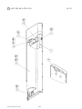
11 - 1 REMOVING THE SHIFT LEVER
1 By following "10-1 REMOVING THE HANDLE MECHA", turn power off, remove the
STEERING HANDLE, and remove the CONTROL PANEL COVER.
2 Take out the 4 Hexagon Bolts.
HEXAGON BOLT (4)
M8 X 20,w/spring
washer
3 Remove the SHIFT LEVER. The SHIFT
PHOTO 11. 1 a
LEVER has wiring connector. Pull up
the SHIFT LEVER slowly until the 2
connectors can be seen.
4 Disconnect the 2 connectors.
Disconnect the connector.
PHOTO 11. 1 b
57
www.seuservice.com
11 - 2 SWITCH REPLACEMENT
Each Microswitch is secured with 2 screws. Remove the 2 screws and replace the Microswitch.
MICROSWITCH
509-5636
PHOTO 11. 2
SCREW (2)M2.3 X 12,
w/flat & spring washers
FIG. 11. 2
After replacing the Switch, check to see if the switch is inputted as per Shift Lever operation in
the Test Mode.
www.seuservice.com
58
12. ACCELERATOR & BRAKE
Before starting to work, ensure that the Power SW is OFF. Failure to observe
this can cause electric shock or short circuit.
Use care so as not to damage wirings. Damaged wiring can cause electric
shock or short circuit.
Do not touch undesignated places. Touching places not designated can cause
electric shock or short circuit.
This work should be performed by the Location's Maintenance Man or
Serviceman. Performing work by non-technical personnel can cause electric
shock hazard.
When performing work such as parts replacement other than those specified
in this manual, be sure to contact where you purchased the product from.
Confirm the work procedures and obtain precautions from where you
purchased the product prior to performing work. Inappropriate parts
replacement and/or installation with erroneous adjustment can cause an
overload or the parts to come into contact, resulting in an electric shock, a
short circuit, and a fire.
After having performed adjustment or replacement of the volume, be sure to check
the variation of the volume value in the INPUT TEST in the test mode.
STOP
IMPORTANT
If Accel. and Brake operation is not satisfactory, adjustment of volume installation position or
volume replacement is needed. Also, be sure to apply greasing to the gear mesh portion once
every 3 months.
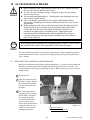
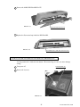
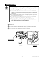
12 - 1 REMOVING THE ACCELERATOR AND THE BRAKE
Remove the accelerator and the brake to perform maintenance. To remove the accelerator and
the brake, a socket wrench for M6 Hexagon bolts and an extension tool are necessary. The
wiring connector is inside the accelerator and the brake. When removing, use care so as not to
damage wiring.
1 Turn power off.
2 Apply the extension tool to
the socket wrench. Remove
the 4 Hexagon bolts which
secure the accelerator and
the brake.
3 The 2 wire connectors are
connected to the accelerator
and the brake. Disconnect
the connectors, and the
accelerator and the brake
can be removed. Since
work is performed inside the
energized cabinet, be very
careful so as not to touch
undesignated portions.
PHOTO 12. 1
HEXAGON BOLT (4)
M6 X 25,black,w/spring washer
59
www.seuservice.com
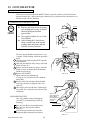
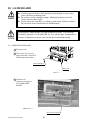
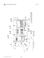
12 - 2 ADJUSTING OR REPLACING THE VOLUME
The appropriate value for both ACCEL. Volume and Brake Volume is under 30H when released
and over C0H when stepped on. Check Volume values in the TEST mode. Since work is
performed inside the energized cabinet, be very careful so as not to touch undesignated places.
Touching places not specified can cause electric shock or short circuit.
ADJUSTMENT
TRUSS SCREW(2)
M4 X 8,chrome
1 Take out the 2 truss screws and remove the
Front Cover from the Accel. & Brake Unit
(FIG. 12. 2 a).
FIG. 12. 2 a
FRONT COVER
2 Loosen the screw which secure the Potentiobase, and adjust the Volume value by moving the
Base. (FIG. 12. 2 b)
3 Secure the Potentiobase.
4 In the INPUT TEST screen, check to see if the volume value varies in accordance with operation of the pedal.
SCREW
M5 X 12,w/flat &
spring washers
POTENTIOBASE
V.R.Å
220-5484
220-5373
www.seuservice.com
FIG. 12. 2 b
60
REPLACEMENT
TRUSS SCREW(2)
M4 X 8
1 Turn the power off.
2 Take out the 2 screws and remove
POTENTIOCOVER
the Potentiocover (FIG. 12. 2 c).
3 Disconnect the connector of the
volume to be replaced.
4 Remove the screw which secures
the Potentiobase (FIG. 12. 2 b).
5 Remove the Potentiobase together
with the volume as is attached.
(FIG. 12. 2 c)
6 Remove the base and the gear to
replace the volume.
7 After replacing, check to see if the
volume values varies in
accordance with operation of the
pedal.
POTENTIOBASE
FIG. 12. 2 c
12 - 3 GREASING
STOP
Be sure to use the designated grease. Using undesignated grease can cause parts
damage.
IMPORTANT
Once every 3 months, apply
greasing to the Spring and gear
mesh portion. For spray
greasing, use GREASE MATE
(PART No. 090-0066).
GREASING
FIG. 12. 3
61
www.seuservice.com
13. COIN SELECTOR
HANDLING THE COIN JAM
If the coin is not rejected when the REJECT button is pressed, open the coin chute door and
open the selector gate. After removing the jammed coin, put a normal coin in and check to see
that the selector correctly functions.
CLEANING THE COIN SELECTOR
GATE
Remove and clean smears by using a
soft cloth dipped in water or diluted
chemical detergent and then
squeezed dry.
Never apply machine oil, etc. to the
Coin Selector.
After cleaning the Coin Selector,
insert a regular coin in the normal
working status and ensure that the
Selector correctly functions.
STOP
IMPORTANT
1
2
3
4
5
6
FIG. 13 a
The coin selector should be cleaned once every
3 months. When cleaning, follow the procedure
below:
Turn the power for the machine OFF. Open the
coin chute door.
Open the gate and dust off by using a soft brush
(made of wool, etc.).
Remove and clean smears by using a soft cloth
dipped in water or diluted chemical detergent
and then squeezed dry.
Remove the CRADLE.
When removing the retaining ring
(E ring), be very careful so as not to bend the
rotary shaft.
Remove stain from the rotary shaft and shaft
receiving portions by wiping off with a soft
cloth, etc.
After wiping off as per áD above, further apply
a dry cloth, etc. to cause the coin selector to dry
completely.
COIN INSERTION TEST
Once every month, when performing the
Coin SW Test, simultaneously check the
following:
Does the Coin Meter count satisfactorily?
Does the coin drop into the Cashbox
correctly?
Is the coin rejected when inserted while
keeping the Reject Button pressed down?
www.seuservice.com
62
CRADLE
FIG. 13 b
Insert a coin
while keeping the
Reject Button
pressed down and
check if it is
rejected.
COIN METER
FIG. 13 c
OPTIONAL DOLLAR BILL ACCEPTOR
THE COIN DOOR ASSEMBLY USED ON 18 Wheeler Deluxe COMES
EQUIPPED TO ACCEPT A DOLLAR BILL ACCEPTOR. ALL NEEDED
WIRING CONNECTIONS ARE CONVIENENTLY LOCATED INSIDE THE
GAME FOR THIS APPLICATION.
THE COIN DOOR CAN ACCCOMMODATE THE FOLLOWING
VALIDATOR(S):
FORWARD-MOST
HOLE POSITION
**42-1155-00
Mars 2000 series
MARS VALIDATOR $1, 2, 5 300 CAP
The frame and cashbox enclosure on this coindoor has been modified to accomodate
a Mars 2000 series upstacker. A 2000 series stacker can be added by simply removing the cut-out plate. This one entry door can be ordered through Happ Controls or
one of Happ Controls authorized distributors. The part number is 40-6000-10EX.
The Mars stacker can be obtained through an autherized Mars distibutor.
Note: Your game may have either Happ Controls Coin Door Assembly or the Wells
Gardner Coin Door Assembly (not shown).
**Happ part number
Security Locking Bar/Bracket Set Part No.# 999-0966
Modified Cash Box (For use when DBA installed)
Part No. # 999-1106
Plastic Cash Box - Full Size Part No. # 999-1177
63
www.seuservice.com
www.seuservice.com
64
K
L
29
7
5
J
5
C
1
B
2
5
28
17
F
18
D
G
27
E
H
A
M
14
6
12
26
2701 N. KILDARE CHICAGO, IL 60639
1-800-336-6630
WWW.WGEC.COM
ELECTRONICS CORPORATION
WELLS-GARDNER
24
25
11
19
3
16
15
20
8
4
22
21
13
9
23
10
8
4
812-4050-011
2
DESCRIPTION
REJECT FLAP
NUT KEPS #8-32 X 5/16 HEX
891-1109-16
020X1877-005
22
23
BRACKET, LAMPSIDE
BRACKET, COVERSIDE
BRACKET, HOLD DOWN
892-1002-021
892-1002-10
28
29
MINI DOOR W/DBV C/O
892-1002-01
27
MINI DOOR 2 ENTRIES
891-0614-16
26
SCREW, PAN HEAD
891-0604-16
25
SLEEVE, SNAP-ON
892-1002-11
24M
ELASTIC SNAP NUT
892-1002-09
24L
CLIP, SNAP-ON
892-1002-08
COVER, PLASTIC
MICROSWITCH, BLACK - MED.
24K
891-1125-00
24H
ADJUSTER, COIN
BRACKET, MICROSWITCH
REJECT CUP BASE PLATE
892-1002-07
891-1116-16
24G
KEP NUT
REJECT CUP SIDE PLATE
24J
891-1110-00
24F
891-1106-00
24D
891-1107-00
891-1105-01
24C
24E
890-1206-02
24B
SCREW,FLAT HEAD M/S
REJECT BEZEL, NYLON
891-1312-16
21
MICROSWITCH ASSEMBLY
BUTTON BEZEL, NYLON
891-1311-16
20
890-1007-00
SPRING, E/R BUTTON
891-1121-00
19
24A
LAMP WEDGE BASE 6 VOLT
891-1118-00
18
891-2216-16
LAMPHOLDER
891-1117-00
24
E/R BUTTON US $1 COIN RIGHT
891-1113-011
17
BASE PLATE ASSEMBLY
E/R BUTTON US 4x25c/$1 LEFT
891-1113-03
15
16
COVER PLATE
891-1008-107
LOCK SINGLE BIT
14
891-0547-00
METAL CASHBOX
DOUBLE FRAME
891-0100-4016
13
12
11
891-0509-162
ENCLOSURE W/CHUTE
025X3712-001
025X3711-001
9
10
CLAMP UK 5/8" CABINET
891-0514-00
8
KEYHOOK
WASHER INTERNAL TOOTH 3/4"
890-1019-00
6
890-1300-00
SCREW TRILOBULAR
890-1017-00
5
7
CLAMP SCREW
890-1003-00
HINGE SCREW
S-10 US $1 COIN MECH RIGHT
S-7 US 25c COIN MECH LEFT
4
890-1002-00
812-4150-011
3
W.G. PART #
#
1
WGD15-2110-01
OVER/UNDER MINI DOOR
2 ENTRIES WITH BILL
VALIDATOR
BOTTOM DOOR
& SPECIAL ENCLOSURE
65
www.seuservice.com
Tom Happ
Ph: 847-593-6161 ext. 107
[email protected]
Fx: 847-956-2091
Happ Controls, 106 Garlisch Drive, Elk Grove, IL 60007
Visit our website http://www.happcontrols.com
Guardian Hasp
30-2400-200
14. PROJECTOR
Since the Projector has been adjusted at the time of shipment, avoid making
further adjustments without good reason.
STOP
IMPORTANT
The Projector is subject to color deviation due to Convergence deviation caused
by the geomagnetism at the installation location and peripheral magnetic field.
After the installation of machine, and before commencing operation, check for
Convergence deviation and if deviated, make adjustments.
Projector adjustments are stored. Due to distortion or color deviation in the TEST mode, if an
adjustment is necessary, use the Remote Control to make adjustments. There are two Projector
Makers (Toshiba and Mitsubishi) and the adjustment method varies depending on the specific
maker.
14 - 1 CLEANING THE SCREEN
Since the Projector screen is susceptible to damage, pay careful attention to its
handling. When cleaning, refrain from using water or volatile chemicals.
When the screen surface
becomes dirty with dust,
etc., clean it by using a
soft cloth such as gauze.
When water, and volatile
chemicals such as
benzine, thinner, etc., spill
on the screen surface, it
may be subject to damage,
therefore, do not use
them. Also, since the
surfaces are susceptible to
damage, refrain from
rubbing them with a hard
material or using a duster.
FIG. 14. 1
www.seuservice.com
66
14 - 2 ADJUSTMENT OF TOSHIBA PROJECTOR
SETTING THE INTERFACE
STOP
IMPORTANT
In this product, set to INPUT LEVEL: 0.7V and IMPEDANCE: 75É∂. Failure
to observe this can cause CRT membrane to burn or Shutdown device to function
resulting in power off.
The Projector's Connector Panel contains the Interface setting SW.
WINNER
LAMP
COM
AC IN
AC100-120V~
AC100-120V~
IMPEDANCE
RGB IN
HIGH
INPUT LEVEL
75 ¶ @ @0.7V
1~3V
REMOTE CONTROL BUTTONS
When adjusting the Projector, direct the Remote Control's light emitting portion towards the
Projector Screen.
REMOTE CONTROL LIGHT EMITTING PORTION
MODE (mode selection)
TEST
MODE
WRITING
R
G
B
P
TEST (adjust/normal shift)
R. G. B. (color selection)
WRITING (storing the data)
P (automatic color matching)
SET
SET (to decide the selection)
PIC - ADJ (item selection)
PIC-ADJ
POSITION
POSITION (to select the position)
RESET
RESET
ADJUST
SELECT (pattern selection)
ADJUST (adjustment)
SELECT
67
www.seuservice.com
AUTOMATIC COLOR MATCHING
The Projector may be subject to color deviations affected by earth magnetism, the building steel
frames, etc. When the Projector is initially installed or the Projector's installation position is
changed, have the color matching performed automatically.
1 Keep pressing the P button (red) for approximately 3 seconds to have
the ensuing movements performed automatically.
TEST
MODE
WRITING
R
G
B
POSITION
ADJUST
The Projector will shift to the color deviation
correction mode from the game mode, with
the green cross pattern appearing on the
screen.
P
SET
PIC-ADJ
RESET
SELECT
The cross pattern moves up/down and right/
left to start the movement of searching the correct screen position and inclination.
When the green cross pattern movements are finished, similar detection
is performed sequentially in order of red and then blue cross movements. After detecting by green, red and blue cross movements, the
game mode returns with the color deviation status being corrected.
Although very rarely, the TRY AGAIN error display in red may appear. At this time, press the
P button (red) for approximately 3 seconds.
Even after the above operation is repeated, if the error condition still exists, then the display
shifts to PLEASE ADJ. In this case, the auto color matching function can not be used. Contact
the place of contact herein stated or where the product was purchased from.
If the automatic color matching indicates an error, color matching can manually be performed.
Refer to CONVERGENCE ADJUSTMENT (manual color matching).
www.seuservice.com
68
ADJUSTING THE ON-SCREEN CONTRAST
Although the on-screen picture quality has been adjusted at the time of shipment from the
factory, the on-screen contrast can be readjusted if desired. When the Game Board is replaced,
readjustment may be necessary. Changing the CONTRAST causes the light and shade of the
on-screen images to be changed.
1 Press either
or
PIC - ADJ button.
CONTRAST
BRIGHTNESS
H.POSI
V.POSI
H.SIZE
V.SIZE
EXIT
PIC-ADJ
TEST
MODE
WRITING
R
G
B
POSITION
ADJUST
P
SET
The on-screen menu will
have one item in purple and
6 items in white.
PIC-ADJ
RESET
SELECT
Herein,
procedure 2
is skipped.
2 Choose CONTRAST by using either
or
PIC - ADJ button.
PIC-ADJ
SET
CONTRAST
BRIGHTNESS
H.POSI
V.POSI
H.SIZE
V.SIZE
EXIT
Have CONTRAST displayed in purple. Since
CONTRAST is selected
initially, no particular
operation is required in this
case.
3 Press the SET button (to decide selection).
When the selection of the
CONTRAST adjustment
mode is decided, the
adjustment data scale bar
appears on the screen.
CONTRAST
230
. . . . . . . . . . . . . . . . . . . .
4 Make adjustment by using either
ADJUST
or
ADJUST button.
As the Cursor is moved, the
adjustment data value
changes. Make adjustment
so as to obtain the desired
on-screen contrast status.
CONTRAST
156
. . . . . . . . . . . . . . . . . . . .
WRITING
5 Press the WRITING button (for storing and finish).
The WRITING display
appears and the adjustment
data is stored.
WRITING
When discontinuing the adjustment, choose EXIT from the menu at the stage of procedure 2 and press
the SET button.
To continue adjusting other menu items, repeat procedure 2 ~ 4 .
Unless the adjustment data is stored, the data in the adjusted status will be erased at the time the power
is turned off and the pre-adjustment status will remain when the power is turned on next time.
69
www.seuservice.com
ADJUSTING THE SCREEN BRIGHTNESS
Although the on-screen picture quality has been adjusted at the time of shipment from the
factory, readjustment can be made if desired. When the Game Board is replaced, readjustment
may be necessary. Changing the BRIGHTNESS causes the brightness of the on-screen images
of black portions to be changed.
1 Press either
PIC-ADJ
TEST
MODE
WRITING
R
G
B
POSITION
P
SET
or
CONTRAST
BRIGHTNESS
H.POSI
V.POSI
H.SIZE
V.SIZE
EXIT
PIC - ADJ button.
The on-screen menu will have one
item in purple and 6 items in
white.
PIC-ADJ
2 Choose BRIGHTNESS by using either
ADJUST
or
PIC
- ADJ button.
RESET
PIC-ADJ
SELECT
SET
CONTRAST
BRIGHTNESS
H.POSI
V.POSI
H.SIZE
V.SIZE
EXIT
Have the BRIGHTNESS displayed
in purple.
3 Press the SET button (to decide selection).
When the selection of the
BRIGHTNESS adjustment mode
is decided, the adjustment data
scale bar appears on the screen.
BRIGHTNESS
128
....................
4 Make adjustment by using either
ADJUST
or
ADJUST
button.
As the Cursor is moved, the
adjustment data value changes.
Make adjustment so as to obtain
the desired on-screen brightness
status.
BRIGHTNESS
156
....................
WRITING
5 Press the WRITING button (for storing and finish).
The WRITING display appears
and the adjustment data is stored.
WRITING
When discontinuing the adjustment, choose EXIT from the menu at the stage of procedure 2 and press
the SET button.
To continue adjusting other menu items, repeat procedure 2 ~ 4 .
Unless the adjustment data is stored, the data in the adjusted status will be erased at the time the power
is turned off and the pre-adjustment status will remain when the power is turned on next time.
www.seuservice.com
70
ADJUSTING THE ON-SCREEN DISPLAY POSITION
Although the on-screen display position (H. POSI, V. POSI) has been adjusted at the time of
shipment from the factory, readjustment can be made if desired. When the Game Board is
replaced, readjustments may be necessary.
1 Press either
PIC-ADJ
TEST
MODE
WRITING
R
G
B
POSITION
P
SET
or
CONTRAST
BRIGHTNESS
H.POSI
V.POSI
H.SIZE
V.SIZE
EXIT
PIC - ADJ button.
The on-screen menu will have
one item in purple and 6 items in
white.
PIC-ADJ
2 Choose H. POSI or V. POSI by using either
ADJUST
or
PIC ADJ button.
RESET
PIC-ADJ
SELECT
CONTRAST
BRIGHTNESS
H.POSI
V.POSI
H.SIZE
V.SIZE
EXIT
SET
Have the H. POSI or V. POSI
displayed in purple. The Figure
shows the status in which H.
POSI is selected.
3 Press the SET button (to decide selection).
When the selection of the H.
POSI or V. POSI is decided, the
adjustment data scale bar appears
on the screen.
H.POSI
128
. . . . . . . . . . . . . . . . . . . .
4 Make adjustment by using either
ADJUST
or
ADJUST
button.
When making adjustments
in vertical directions, also
use either
or
ADJUST button.
WRITING
As the Cursor is moved, the
adjustment data value changes.
Make adjustment so as to obtain
the desired on-screen position
status.
H.POSI
156
. . . . . . . . . . . . . . . . . . . .
5 Press the WRITING button (for storing and finish).
The WRITING display appears
and the adjustment data is stored.
WRITING
When discontinuing the adjustment, choose EXIT from the menu at the stage of procedure 2 and press
the SET button.
To continue adjusting other menu items, repeat procedure 2 ~ 4 .
Unless the adjustment data is stored, the data in the adjusted status will be erased at the time the power
is turned off and the pre-adjustment status will remain when the power is turned on next time.
71
www.seuservice.com
ADJUSTING THE SCREEN SIZE
Although the on-screen size (H. SIZE, V. SIZE) has been adjusted at the time of shipment from
the factory, readjustment can be made if desired. When the Game Board is replaced,
readjustments may be necessary.
1 Press either
PIC-ADJ
TEST
MODE
WRITING
R
G
B
POSITION
P
SET
or
CONTRAST
BRIGHTNESS
H.POSI
V.POSI
H.SIZE
V.SIZE
EXIT
PIC - ADJ button.
The on-screen menu will have one
item in purple and 6 items in
white.
PIC-ADJ
2 Choose H. SIZE or V. SIZE by using either
ADJUST
or
PIC - ADJ button.
RESET
PIC-ADJ
SELECT
CONTRAST
BRIGHTNESS
H.POSI
V.POSI
H.SIZE
V.SIZE
EXIT
Have the H. SIZE or V. SIZE
displayed in purple. The Figure
shows the status in which H. SIZE
is selected.
3 Press the SET button (to decide selection).
SET
When the selection of the H. SIZE
or V. SIZE adjustment mode is
decided, the adjustment data scale
bar appears on the screen.
H.SIZE
128
. . . . . . . . . . . . . . . . . . . .
4 Make adjustment by using either
or
ADJUST
button.
ADJUST
When making adjustments
in vertical directions, also
use either
or
button.
WRITING
As the Cursor is moved, the
adjustment data value changes.
Make adjustment so as to obtain
the desired on-screen position
status.
H.SIZE
156
. . . . . . . . . . . . . . . . . . . .
5 Press the WRITING button (for storing and finish).
The WRITING display appears
and the adjustment data is stored.
WRITING
When discontinuing the adjustment, choose EXIT from the menu at the stage of procedure 2 and press
the SET button.
To continue adjusting other menu items, repeat procedure 2 ~ 4 .
Unless the adjustment data is stored, the data in the adjusted status will be erased at the time the power
is turned off and the pre-adjustment status will remain when the power is turned on next time.
www.seuservice.com
72
CONVERGENCE ADJUSTMENT (manual color matching)
To avoid circuitry malfunctioning due to electrical load increase, never utilize
CONVERGENCE ADJUSTMENT (Line Convergence Adjustment in particular)
for adjusting screen size changes.
There is no means to restore the Convergence Adjustment data once stored, to its
original state. To avoid changing the screen size by erroneously using
convergence adjustment, do not perform the green Line Convergence Adjustment.
As such, be sure to perform the adjustment work from this page onward by the
Technical staff and the location's Maintenance Personnel who are well versed in
such adjustment work. In the Static Convergence Adjustments, if satisfactory
adjustments can not be performed, do not make another convergence adjustments
inadvertently. Contact the office herein stated or where the product was
purchased from.
STOP
IMPORTANT
To avoid making the adjustment work ineffective, do not press the RESET
button during adjustment.
To discontinue adjustment work, keep pressing the TEST button for
approximately 3 seconds at the stage before storing the adjustment data by
pressing the WRITING button.
Should the screen be abnormally disturbed by noise due to static electricity,
etc., turn the power off without storing the adjustment data.
Pressing the
or
PIC - ADJ
button in the Convergence Adjustment
mode status will display the
Adjustment Menu shown right. Do not
utilize this Adjustment Menu as this is
the one applied at the factory.
Adjusting this menu causes the
Customer's adjustment range to be
deviated.
Should the menu shown right be
displayed by mistake, first choose
EXIT by using either
or
PIC ADJ button and then press the SET
button.
73
ADJUST MODE
SUB VSIZE
SUB HSIZE
SUB BRIGHT
EXIT
Adjustment menu used in the factory.
www.seuservice.com
STATIC CONVERGENCE ADJUSTMENT
In the static convergence adjustment, each of red and blue images is comprehensively moved to
and superimposed on the green color. If automatic color matching function is not sufficiently
satisfactory, perform this adjustment. Be sure to perform automatic color matching before
starting the above adjustment.
1 Keep pressing the TEST button for
approximately 3 seconds.
TEST
MODE
WRITING
P
ADJUST MODE
R
G
B
POSITION
SET
PIC-ADJ
DO NOT PUSH THIS.
ADJUST
The screen will change to
ADJUST mode from the Game
mode to cause the green test
pattern to be displayed on the
screen.
2 Press the R button to have the red adjustment
mode.
RESET
ADJUST MODE
SELECT
The red test pattern is added to
the display. The frame color
turns red and this signifies the
red adjustment mode.
3 Make adjustment by using the
When either of 2 4 COLOR
SELECT buttons (R, B) is pressed, if the
color desired to be adjusted disappears,
press that particular button again. For
example, if the red color needs to be
adjusted again at the stage of 4 , the R
button need to be pressed twice.
ADJUST buttons.
ADJUST MODE
Make adjustment so as to have
red superimposed on green.
When red is superimposed on
green, the color becomes
yellow.
4 Press the B button to have the blue adjustment
mode.
ADJUST MODE
Similarly as in the case of red,
adjust the blue color. When
green, red, and blue are superimposed, the color becomes
white.
5 Press the WRITING button (for storing and finish).
ADJUST MODE
WRITING
www.seuservice.com
74
The WRITING display appears
and the adjustment data is
stored. After the data is stored,
the Game mode returns.
POINT CONVERGENCE ADJUSTMENT
In the POINT CONVERGENCE adjustment, each of red, green and blue images is partially
moved for color matching. The adjustment may be necessary when the Game Board is replaced or
changed, or screen size is changed. Be sure to perform automatic color matching before starting
the adjustment.
1 Keep pressing the TEST button for
approximately 3 seconds.
ADJUST MODE
TEST
MODE
WRITING
R
G
B
P
2 Press the MODE button twice to have the POINT
ADJUSTMENT mode. Note 1
SET
ADJUST MODE
MARKER
POSITION
ADJUST
The screen changes to ADJUST
mode from the Game mode and
displays the green test pattern.
PIC-ADJ
RESET
DO NOT
PRESS.
The crosshatch test pattern appears
and the MARKER indicating the
adjustment point is displayed.
3 Using either R or B button, select the desired
color to be adjusted. Note 2 By using the G
button, the green color can also be selected.
SELECT
ADJUST MODE
The selected color is displayed by
superimposing on green. The
MARKER will be in the color
selected.
4 By using the
ADJUST buttons,
move the MARKER to the position to be adjusted.
Note 1 When the MODE button is repeatedly
pressed, the adjustment modes will
circulate as follows:
ADJUST MODE
STATIC ADJUSTMENT MODE
LINE ADJUSTMENT MODE
The MARKER moves in the
direction of the button's arrow.
However, the movable point is
predetermined.
5 Make adjustment by using the
ADJUST buttons.
POINT ADJUSTMENT MODE
Note 2 When either of the COLOR SELECT
buttons (R, B) is pressed, if the desired
color to be adjusted disappears, press
that particular button again.
Although the direct vicinity of the
MARKER's center moves most
conspicuously, make adjustment
by paying attention to the periphery area also. Shown left is the
magnified MARKER periphery.
6 Press the SELECT button as necessary to
superimpose Game Board images. Note 3
Note 3 By repeatedly pressing the SELECT
button, only the Projector's TEST
pattern screen and the screen
superimposing the Game Board Test
pattern can be alternately displayed.
ADJUST MODE
If the test pattern is not displayed in
the periphery of the screen, adjustments can be made by pressing the
SELECT button to superimpose the
test pattern and the Game Board's
CRT test screen.
7 Press the WRITING button (for storing and finish).
ADJUST MODE
WRITING
75
WRITING is displayed and the
adjustment data is stored. After the
data is stored, the Game Board
screen returns.
www.seuservice.com
LINE CONVERGENCE ADJUSTMENT
In the LINE CONVERGENCE ADJUSTMENT, the adjustment point of the column line (vertical) or row line (horizontal) is comprehensively moved for color matching. It is convenient to
utilize this adjustment when the color of the column line or row line is uniformly deviated.
1 Keep pressing the TEST button for approximately
3 seconds.
TEST
MODE
WRITING
R
G
B
POSITION
ADJUST
ADJUST MODE
P
SET
PIC-ADJ
RESET
The screen changes to ADJUST
mode from the Game Board mode
and displays the green test pattern.
2 Press the MODE button once to have the POINT
ADJUSTMENT mode. Note 1
DO NOT
PUSH.
SELECT
ADJUST MODE
MARKER
The crosshatch test pattern appears
and the vertically long MARKER
is shown.
- 3 Using either R or B button, select the desired color to
be adjusted. Note 2 Although the green color can also
be selected by using the G button, to avoid the screen
size change adjustment, do not choose green.
ADJUST MODE
Note 1 When the MODE button is repeatedly
pressed, the adjustment modes will
circulate as follows:
STATIC ADJUSTMENT MODE
The selected color is displayed by
superimposing on green. The
MARKER will be in the color
selected.
4 By using the
POSITION buttons,
move the MARKER to the position to be adjusted.
LINE ADJUSTMENT MODE
ADJUST MODE
POINT ADJUSTMENT MODE
Note 2 When either of the COLOR SELECT
buttons (R, B) is pressed, if the desired
color to be adjusted disappears, press
that particular button again.
ADJUST MODE
Use the
buttons to select
the column line, and the MARKER
moves in the right/left direction.
However, the movable range is
predetermined.
Use the
buttons to select
the row line and the MARKER
moves in the up/down direction.
However, the movable range is
predetermined.
5 Make adjustment by using the
ADJUST buttons.
ADJUST MODE
The selected column line or row
line (shown left is the column line)
can be moved in the desired up/
down or right/left directions as
applicable.
6 Press the WRITING button (for storing and finish).
ADJUST MODE
WRITING
www.seuservice.com
76
WRITING is displayed and the
adjustment data is stored. After
the data is stored, the Game Board
screen returns.
14 - 3 ADJUSTMENT OF MITSUBISHI PROJECTOR
STOP
IMPORTANT
For the operation of Remote Control, use only the Keys of R/B,
(UP shift), (LEFT shift),
(DOWN shift),
(RIGHT shift), TEST,
- , + , and PICTURE. Do not press keys other than those explained in this
manual.
When operating the Remote Control, have it point the screen.
The Projector has DYNAMIC CONVERGENCE adjustment functions. This manual does not
refer to the functions as the adjustment of DYNAMIC CONVERGENCE is very troublesome
and in addition, visual effects are negligible.
(UP shift)KEY
R/B KEY
POWER
(RIGHT shift)KEY
(LEFT shift)KEY
R / B
R / G / B
(DOWN shift)KEY
TEST
1
ENTER
8
9
10
TEST KEY
R-MUTE G-MUTE B-MUTE
+ KEY
-- PICTURE +
MITSUBISHI
- KEY
PICTURE KEY
77
www.seuservice.com
• POWER KEY......................... This does not have power ON/OFF function.
Does not function even if it is pressed.
• R/B KEY ................................ Used to select "R" for red adjustment or "B" for blue adjustment in the
STATIC CONVERGENCE ADJUSTMENT mode.
•s(UP shift) KEY .................... Used to move the test cross upward in the STATIC CONVERGENCE
ADJUSTMENT mode.
•
(LEFT shift) KEY ............ Used to move the test cross to the left in the STATIC CONVERGENCE
ADJUSTMENT mode.
•t (DOWN shift) ...................... Used to move the test cross downward in the STATIC CONVERGENCE
ADJUSTMENT mode.
•
(RIGHT shift) KEY........... Used to move the test cross to the right in the STATIC CONVERGENCE
ADJUSTMENT mode.
• TEST KEY ............................. This is the ON/OFF key in the STATIC CONVERGENCE ADJUSTMENT
mode. In the ON status of this key, the test cross pattern appears in the
approximately on-screen center.
• ENTER KEY ......................... Used for DYNAMIC CONVERGENCE.
• - KEY ..................................... Used to decrease the adjustment data in the adjustment mode of CONTRAST, BRIGHTNESS, HORIZONTAL/VERTICAL POSITIONS and
WIDTH.
• + KEY .................................... Used to increase the adjustment data in the adjustment mode of CONTRAST, BRIGHTNESS, HORIZONTAL/VERTICAL POSITIONS and
WIDTH.
• PICTURE KEY ...................... Used for the ADJUSTMENT mode of CONTRAST, BRIGHTNESS, HORIZONTAL/VERTICAL POSITIONS and WIDTH.
Every time this key is pressed, the ADJUSTMENT mode proceeds as
follows:
NORMAL
OPERATION
CONTRAST
ADJUSTMENT
MODE
BRIGHTNESS
ADJUSTMENT
MODE
H-POSI
ADJUSTMENT
MODE
V-HEIGHT
ADJUSTMENT
MODE
V-POSI
ADJUSTMENT
MODE
H-WIDTH
ADJUSTMENT
MODE
EXPLANATIONS OF ADJUSTMENT MODES
• CONTRAST ................ Used to vary image contrast. Use + and - keys to adjust.
• BRIGHTNESS ............ Used to change image brightness. Use + and - keys to adjust.
• H-POSI ........................ Used to move the image position in the horizontal direction. Use + and - keys to
adjust.
• H-WIDTH ................... Used to change the horizontal width of image. Use + and - keys to adjust.
• V-POSI ........................ Used to move the image position in the vertical direction. Use + and - keys to
adjust.
• V-HEIGHT .................. Used to change the vertical width of image. Use + and - keys to adjust.
www.seuservice.com
78
STATIC CONVERGENCE ADJUSTMENT
Press the TEST KEY to change the screen to Red Line
Adjustment mode.
RED 31K
H:+75 V:-11
+
Superimpose the red line on the green line.
When the red line is superimposed on the green line, the
green line turns to yellow or white.
R
To MOVE RED LINE:
Use key to move it left.
Use key to move it right.
Use s key to move it upward.
Use t key to move it downward.
Press the R/B KEY.
Changes to the Blue Line Adjustment screen.
Every time the key is pressed, "from red to blue" and
"from blue to red" are alternated.
SUPERIMPOSING BLUE LINE ON GREEN LINE:
Superimposing blue line on green line causes the green
line to turn to white.
B
TO MOVE BLUE LINE:
Use key to move it left.
Use key to move it right.
Use s key to move it upward.
Use t key to move it downward.
Press the TEST KEY.
Adjustment is finished.
AUTOMATIC CANCELLATION OF ADJUSTMENT MODE
In each adjustment mode, only in the case where an effective key input (variation of values and
images) is not performed within the time limit indicated below, the adjustment mode is
automatically cancelled and finished, shifting to on-screen normal images.
Approximately 6 seconds
Approximately 5 min.
CONTRAST
BRIGHTNESS
H-POSI
H-WIDTH
V-POSI
V-HEIGHT
STATIC CONVERGENCE
79
www.seuservice.com
15. REPLACING THE FLUORESCENT LAMP, AND LAMPS
When performing work, be sure to turn power off. Working with power on
can cause electric shock and short circuit hazards.
The Fluorescent Lamp, when it gets hot, can cause burn. Be very careful
when replacing the Fluorescent Lamp.
Be sure to use lamps of the designated rating. Using lamps of undesignated
rating can cause a fire or malfunctioning.
To perform work safely and securely, be sure to prepare a step which is in a
secure and stable condition. Performing work without using the step can
cause violent falling down accidents.
Be careful when handling the plastic made parts. Failure to observe this may
cause injury due to damage or fragments resulting from damage.
THE FLUORESCENT LAMP INSIDE THE MAIN BILLBOARD
1 Turn off power.
2 Take out the 3 screws to remove the SASH.
TRUSS SCREW (3)
M4 X 16,chrome
PHOTO 15 a
SASH
When performing work,
be sure to use a step.
PHOTO 15 b
www.seuservice.com
80
3 Remove the MAIN BILLBOARD PLATE.
PHOTO 15 c
MAIN BILLBOARD PLATE
4 Replace the fluorescent lamp inside the BILLBOARD.
PHOTO 15 d
FLUORESCENT LAMP 32W: 390-5251-32-01
GLOW BULB: 390-5638-5P
THE BUTTON FOR THE HORN IN THE ASSISTANT DRIVER'S SEAT
A wiring connection is inside the horn button. When removing, use care so as not to damage
wiring.
TRUSS SCREW (4)
M4 X 16,chrome
1 Turn power off.
2 Remove the 4 screws.
PHOTO 15 e
81
www.seuservice.com
3 A wire connector is connected to the horn
button. Disconnect the connector, and the
horn button can be removed.
4 Firmly pinch the switch portion at the
bottom of the button and pull it out of the
button portion.
5 Pull out the lamp vertically and replace.
Disconnect the connector.
Do not turn the lamp at this time.
PHOTO 15 f
LAMP14V 3.8W 390-6677-038
FIG. 15
PHOTO 15 g
START BUTTON & VIEW CHANGE BUTTON
A wiring connection is inside the start
button and the view change button.
When removing, use care so as not to
damage wiring.
1 Turn power off.
2 Take out the 4 screws.
PHOTO 15 h
TRUSS SCREW (4)
M4 X 16,chrome
www.seuservice.com
82
3 A connector is connected to the start
button and the view change button.
Disconnect the connector, and the ASSY
VR BUTTON START & VIEW 1 can be
removed.
Disconnect the connector.
PHOTO 15 i
4 The lamp is on the PCB side. Turn the metallic parts of the 2 buttons, unlock and remove the
PCB from the buttons.
PHOTO 15 j
5 With the lamp pressed down, turn it
counterclockwise to remove.
LAMP 6.3V 1W
390-5445-01
PHOTO 15 k
83
www.seuservice.com
16. PERIODIC INSPECTION TABLE
The items listed below require periodic check and maintenance to retain the performance of this
machine and to ensure safe business operation.
Be sure to check once a year to see if Power Cords are damaged, the plug is
securely inserted, dust is accumulated between the Socket Outlet and the
Power Plug, etc. Using the product with dust as is accumulated can cause fire
and electric shock hazards.
Periodically once a year, request the place of contact herein stated or the
Distributor, etc. where the product was purchased from, as regards the internal
cleaning. Using the product with dust as is accumulated in the interior
without cleaning can cause a fire or accident. Note that cleaning the interior
parts can be performed on a pay-basis.
TABLE 16
Item
Interval
Reference
CABINET
Check Adjusters'contact with surface.
Daily
3
HANDLE MECHA
Check lamp.
Monthly
9
Check VOLUME VALUE.
Monthly
9
Check ADJUST GEAR engagement.
Trimonthly
10-2
Check VOLUME value.
Monthly
6,9
Check ADJUST GEAR engagement.
Trimonthly
12-2
Gear and Spring portion greasing.
Trimonthly
12-3
Check SW.
Monthly
6,9
Monthly
9
Coin insertion test.
Monthly
13
Cleaning of COIN SELECTOR.
Trimonthly
13
SCREEN cleaning.
Weekly
14-1
Check adjustments.
Monthly
6,9,14
MEMORY TEST.
Monthly
9
Check settings.
Monthly
9
Cabinet surfaces
Cleaning
As necessary.
See below.
INTERIOR
Cleaning
Annually
See above.
ACCEL. & BRAKE
SHIFT LEVER
COIN CHUTE TOWER Check COIN SW.
PROJECTOR
GAME BD
POWER SUPPLY PLUG Inspection and cleaning
CLEANING THE CABINET SURFACES
When the cabinet surfaces are badly soiled, remove stains with a soft cloth dipped in water or
diluted (with water) chemical detergent and squeezed dry. To avoid damaging surface finish, do
not use such solvents as thinner, benzine, etc. other than ethyl alcohol, or abrasives, bleaching
agent and chemical dustcloth.
www.seuservice.com
84
17. TROUBLESHOOTING
In order to prevent electric shock and short circuit, be sure to turn power off
before performing work.
Be careful so as not to damage wirings. Damaged wiring can cause electric
shock or short circuit.
After removing the cause of the functioning of the Circuit Protector, reinstate
the Circuit Protector. Depending on the cause of the functioning, using the
Circuit Protector as is without removing the cause can cause generation of
heat and fire hazard.
In case a problem occurs, first check wiring connector connections.
TABLE 17 a
PROBLEMS
CAUSE
COUNTERMEASURES
Power is not supplied.
Securely insert the power plug into the plug
socket.
Power supply/voltage is not correct.
Make sure that power supply/voltage is
correct.
The Circuit Protector functioned
due to the momentary overload.
After eliminating the cause of overload,
reinstate the AC Unit's Circuit Protector
(see 5 , Section 6, Refer to the following).
The color on PTV
screen is
incorrect.
Image adjustment is inappropriate.
Adjust appropriately (see Sec.14).
Color deviation
on PTV screen.
Affected by peripheral machines or
the building's steel frames.
Perform convergence adjustment
(see Sec. 14).
With Main SW
ON, no activation.
Change installation direction or position.
Move the machine which causes the
problem.
CIRCUIT PROTECTOR
CIRCUIT PROTECTOR
Functions due to the activation of
bimetal. To restore the function,
wait for approximately one minute
or longer until the bimetal cools
off. (Press the Button.)
FIG. 17 a
85
www.seuservice.com
TABLE 17 b
PROBLEMS
No sound is
emitted.
CAUSE
COUNTERMEASURES
Sound volume adjustment is not
appropriate.
Adjust sound volume (see Sec. 9).
Board and Amplifier malfunctioning.
Perform the sound test and confirm
(see Sec. 9).
Operation of
Super Woofer and
Base Shaker are
not satisfactory.
The fuse on the AMP BASE is blown.
Replace fuse. (see Fig.17b)
Steering Wheel
reaction strength
is incorrect.
Deviation of
Center.
Power ON check not performed
correctly.
Turn off power and then turn it back on
again. Complete the power on check.
V.R. position deviated.
Adjust V. R. value in the test mode
(see Sec. 9).
V.R. malfunctioning.
Replace V.R. (see Sec. 10).
Steering Wheel
reaction strength
is insufficient.
Reaction Mecha's secular change.
Change the setting in the Test Mode
(see Sec. 9).
No Steering
Wheel Reaction.
Connector Connection is incorrect.
Check the connector's connection inside the
LID TOP FRONT. (see 10-1)
SHIFT LEVER
doesn't operate
satisfactorily.
Switch malfunctioning.
Replace the Switch (see Sec. 11).
Operation of
Accel. and Brake
Pedals are not
satisfactory.
V.R. malfunctioning.
Replace the V.R. (see Sec. 12).
ADJUST GEAR's engagement is not
correct.
Adjust the engagement of ADJUST GEAR
(see Sec. 12).
The Fluorescent
lamp does not
light up.
Connector connection fault.
Check connector connection (see Sec 6).
The Fluorescent tube is burnt out.
Replace the Fluorescent tube (see Sec. 15).
www.seuservice.com
86
REPLACMENT OF FUSE
Fuse replacements other than those specified can cause accidents and are
strictly forbidden. In case fuse replacements other than those stated in this
manual are necessary, contact where you purchased the product from for
inquiries regarding this matter.
In order to prevent an electric shock, be sure to turn power off and unplug
from the socket outlet before performing work by touching the internal parts
of the product.
Be careful so as not to damage wirings. Damaged wiring can cause electric
shock and short circuit accidents.
Be sure to use fuses meeting specified rating. Using fuses exceeding the
specified rating can cause fire and electric shock accidents.
After eliminating the cause of the blowing of fuse, replace the fuse.
Depending on the cause of fuse blowing, continued use with the fuse as is
blown can cause generation of heat and fire hazard.
1 Turn power off.
2 Take out the 2 truss screws, unlock and remove the BACK LID from the main cabinet.
3 The fuse is provided at the right-hand side of the BACK LID inside.
TRUSS SCREW (2)
M4 X 25,black
BACK LID
FIG. 17 b
87
FUSE 6.3A
514-5086-6300
www.seuservice.com
18. GAME BOARD
In order to prevent electric shock and short circuit hazards, be sure to turn
power off before performing work.
Be careful so as not to damage wirings. Damaged wiring can cause fire,
electric shock or short circuit.
Do not expose the Game BD, etc. without a good reason. Failure to observe
this can cause electric shock hazard or malfunctioning.
In this product, setting changes are made during the test mode. The Game BD
need not be operated. Use the Game BD, etc. as is with the same setting made at
the time of shipment so as not to cause electric shock and malfunctioning.
18 - 1 REMOVING THE BOARD
1 Turn power off.
2 Take out the 2 truss screws,
unlock and remove the BACK
LID from the main cabinet.
TRUSS SCREW (2)
M4 X 25,black
BACK LID
FIG. 18. 1
3 Disconnect all
connectors connected to
the NAOMI GAME
BOARD.
PHOTO 18. 1 a
Disconnect the connector
www.seuservice.com
88
4 Disconnect the 4 connectors connected to
the IC BOARD next to the NAOMI
GAME BOARD. It is not necessary to
disconnect the leftmost 2 connectors out
of the 3 connectors on the IC BD.
5 Pull out the 8P connector at the AMP BD
side.
Disconnect the connector
PHOTO 18. 1 b
6 Untie cord clamps and harness lugs which
secure wiring.
Disconnect the connector
PHOTO 18. 1 c
7 Take out the 2 screws which
secure the wooden base carrying
the NAOMI GAME BOARD.
SCREW (2)
M4 X 25,w/flat & spring washers
PHOTO 18. 1 d
8 Pull the base with the NAOMI GAME
BOARD on it out of the main cabinet. At
this time, use care so as not to damage
wiring.
9 Take out the 4 screws to remove the
NAOMI GAME BOARD from the base.
PHOTO 18. 1 e
89
SCREW (4)
M4 X 16,w/flat & spring washers
www.seuservice.com
18 - 2 COMPOSITION OF GAME BOARD
STOP
IMPORTANT
Ensure that the DIP SW setting is performed as designated. Failure to observe
this may cause functioning not suitable for the actual operation, or
malfunctioning.
ASSY CASE NAO PTR USA(840-0023D-01):USA
ASSY CASE NAO PTR EXP(840-0023D-02):OTHERS
ASSY CASE NAO PTR KOR(840-0023D-03):KOREA
ASSY CASE NAO PTR AUS(840-0023D-04):AUSTRALIA
SCREW (4)
M3 X 30
ROM CASE NAO PTR
840-0023C
DIP SW
840-0001A-01 ASSY CASE NAOMI MAIN BD USA
840-0002A-01 ASSY CASE NAOMI MAIN BD EXP
840-0003A-01 ASSY CASE NAOMI MAIN BD KOR
840-0004A-01 ASSY CASE NAOMI MAIN BD AUS
FIG. 18. 2 a
FIG. 18. 2 a
DIP SW
In this product, set the DIP SW to OFF. There is another DIP SW on the IC BOARD (other
than NAOMI GAME BOARD). Set this DIP SW to OFF as well.
FIG. 18. 2 b
www.seuservice.com
90
18 - 3 ERROR DISPLAY (DRIVE CONTROL BOARD)
Be careful so as not to damage wirings. Damaged wiring can cause electric
shock and short circuit hazards.
Do not touch undesignated places. Touching places not specified can cause
electric shock and short circuit hazards.
Inside the LID TOP FRONT is the Drive Control Board. If an irregularity occurs in the Drive
Control Board, the ERROR message is shown on the screen and the 7-SEG display on the Drive
Control Board. Take countermeasures in the manner corresponding to the ERROR message.
Note that even in the case an error occurs, game is playable.
Errors can be classified roughly into 2 types, such as communication related errors between
Drive Control Board & Game Board and the others.
If an error relating to communication occurs, "MOTOR NETWORK ERROR IN: XX OUT:
XX" is displayed on the monitor. "MOTOR TROUBLE CODE: XX" is displayed when an
error relating to other than communication occurs.
For communication error display, the value outputted by NAOMI Board and the value
corresponding to the NAOMI's value outputted by Drive Control Board are displayed. Under
normal operation, these values are identical. However, if an irregularity occurs, the values are
not identical and the results are displayed on the monitor.
If an irregularity relating to other than communication occurs, an error code is displayed.
On-screen ERROR display differs from 7-SEG display on the Drive Control Board. For an
error code and its countermeasures, refer to Table 18.3.
Table 18. 3 ERROR DISPLAY
On-screen
ERROR display
7-SEG display on
Drive Control BD.
ERROR
CAUSE/COUNTERMEASURES
Malfunctioning of Drive Control Board.
Replace Drive Control Board.
e7
ER 01
ROM ERROR
e6
ER 02
RAM ERROR
e0
ER 20
Initialization
setting
irregularity of
motor
Irregularity during initialization setting movement.
Finish initialization setting movement by turning
power off and then on. Note that when ERROR is
displayed,the malfunctioning relates to the Motor
System (Motor, Drive Control BD which controls the
Motor, Drive BD., wirings in between, etc.)
e9
ER 22
Steering Wheel's
centering error
Malfunctioning during initial setting movement.
Finish initialization setting movement by turning
power off and then on. Note that when ERROR is
displayed, the malfunctioning relates to the Steering
Wheel Volume system.
e1
ER 23
ERROR of the
Encoder
incorporated in
the motor.
Malfunctioning which occurs during operation.
First turn the power off and after 10 min., turn it back
on again. Note that when this Error is displayed, the
malfunctioning relates to the Motor System.
e2
ER 24
Overcurrent
ERROR
e3
ER 25
Overheat
Overload
ea
ER 30
VOLUME
ERROR
Malfunctioning which occurs during operation.
Check the variation of the volume value in the test
mode.
91
www.seuservice.com
Among the ERROR display as per Table 18.3, each of Er 01, 02, 20 and 22 (Error Code e7, 6, 0
and 9) is displayed before the Advertise mode is displayed if an irregularity is found during
initialization setting movements when power is turned on.
From among error displays as per Table 18.3, Er 23, 24, 25, and 30 (Error Code e1, 2, 3 and a)
indicate On-Board 7-SEG error display when an irregularity is found during game and
ADVERTISE mode. If an irregularity is found during game, game play can be continued
without Steering Wheel reaction.
If Error display is shown on the screen, remove LID TOP FRONT without turning power off to
check the 7-SEG display on the Drive Control Board. At this time, if the power is turned off,
each of Er 23, 24, 25 and 30 (Error Code e1, 2, 3 and a) which could have occurred during
operation may not be displayed.
Perform the DIP SW setting on the DRIVE CONTROL BOARD as shown below.
DRIVE CONTROL BOARD
DIP SW #1
PHOTO 18. 3
1
2
3
4
5
6
7
8
OFF OFF OFF OFF OFF OFF OFF OFF
DIP SW #2
1
ON
2
ON
3
ON
4
ON
5
6
7
8
ON OFF ON OFF
DIP SW
FIG. 18. 3
www.seuservice.com
92
93
NRP+/.04+.0&DmpIMPC?'
NJ?WGLQRPQFNRPCLE@
NRP+/.04+./&DmpMRFCPQ'
NJ?WGLQRPQFNRPCLE?
NRP+.3//
QRGAICPNRTQGBCJ
NRP+.3/0
QRGAICPNRTQGBCP
NRP+/4.0
QS@@GJJ@M?PBNJ?RC
NRP+/..4
AMLRNLJNJ?RC
NRP+031.
QRCCPGLEFMPLK?PI
NRP+/.63
QRGAICPEPGJJCN?RRCPL
NRP+/.02
QRGAICP@?AINJ?RCAMTCP
NRP+/3.0
K?GL@GJJ@M?PBNJ?RC
NRP+/..1+A
QRGAICPKSDDJCPSLBCP
NRP+/..1+@
QRGAICPKSDDJCP
NRP+04./
QRGAICPTP@SRRML
19. DESIGN RELATED PARTS
For the Warning Display stickers, refer to Section 1.
www.seuservice.com
1 TOP ASSY PTR DX
www.seuservice.com
94
27 PTR-4300
ASSY PWR SPLY
26 PTR-4200
ASSY AMP BD
25 PTR-4100
ASSY CONTROL BD
24 PTR-4000
ASSY MAIN BD
23 PTR-2600
ASSY VR BUTTON START AND 1VIEW
21 PTR-2500
ASSY HANDLE MECHA
20 SPG-2200
ASSY ACCEL&BRAKE
19 PTR-2100
ASSY HIGHT/LOW/BACK SHIFTER
18 PTR-1500
ASSY MAIN BILLBOARD
16 PTR-1200
ASSY COINCHUTE TOWER
15 PTR-1080
ASSY BACK PANEL
28 PTR-2590
ASSY TOP PLATE HANDLE MECHA
22 PTR-2550
SENSOR UNIT
17 INY-1180
SW UNIT
11 STR-1070-01
FAN UNIT OPPOSITE FLOW
13 PTR-1070
ASSY PILLAR L
14 PTR-1075
ASSY PILLAR R
10 STR-1070
FAN UNIT
12 PTR-1060
AC UNIT
6 PTR-1000
ASSY MAIN CABINET
5 PTR-1600
ASSY SUB BILLBOARD
9 PTR-6001
ASSY WIRE
7 PTR-1100
ASSY SUB-CABI
4 PTR-0550
ASSY PTV BASE
8 PTR-1190
ASSY BACK LID
3 PTR-0510
PTV W/STICKER PTR
2 PTR-0500
ASSY PTV
20. PARTS LIST
(D-1/2)
Position of
(Inside the door)
1 TOP ASSY PTR DX
95
www.seuservice.com
1 TOP ASSY PTR DX
PART NO.
DESCRIPTION
1
2
3
4
5
13
14
15
16
17
18
19
20
PTR-0500
PTR-0550
PTR-1000
PTR-1600
421-7308- ~
440-CS0186-EG
440-WS0002XEG
421-7020
421-8479-01
SGM-4365
421-11245-01
440-CS0205-EG
440-CS0206-EG
ASSY PTV
ASSY PTV BASE
ASSY MAIN CABINET
ASSY SUB BILLBOARD
DENOMI SH 1GAME, ~
STICKER C EPILEPSY 40 ENG
STICKER W POWER OFF ENG
STICKER CAUTION FORK
STICKER INSTR SUNLIGHT ENG
POLY COVER 1700 X 2200 X 1700
STICKER CAPACITY 2 SEATS ENG
STICKER C PTR FOR CHILD ENG
STICKER C PTR FOR PROTECTOR EG
201
202
203
204
205
206
207
030-000830-S
068-852216
000-T00540-0C
068-552016-0C
000-T00516-0C
068-552016-0C
008-T00412-0B
HEX BLT W/S M8 X 30
FLT WSHR 8.5-22 X 1.6
M SCR TH CRM M5 X 40
FLT WSHR CRM 5.5-20 X 1.6
M SCR TH CRM M5 X 16
FLT WSHR CRM 5.5-20 X 1.6
TMP PRF SCR TH BLK M4 X 12
401
402
403
405
406
601-6604-70
SGM-2675
420-6545-01
390-6677-038
600-6729
600-6618
600-6695
SGM-4111
220-5576
514-5086-6300
280-5009-01
420-6455-01
509-5636
220-5484
220-5373
CARTON BOX 70
POLYETHYLENE BAG, 240 X 370
OWNERS MNL PTR DX ENG
LAMP WB 14V 3.8W (194)
AC CABLE CONNECT TYPE 15A
AC CABLE CONNECT TYPE FOR EXP
AC CABLE CONNECT TYPE USA 15A
KEY BAG (SGB-1035X)
KEY MASTER FOR 220-5575
FUSE S.B 6300MA 250V HBC CE
CORD CLAMP 21
SERVICE MANUAL NAOMI ENG
SW MICRO TYPE SS-5GL2T
VOL CONT B-5K OHM
VOL CONT B-5K
105-5356
421-8740
421-6690-03
421-6690-05
421-6690-06
421-6690-01
421-6119-91
421-6120-92
SHIPPING BRKT
CAUTION INSTR COP U/R
STICKER 220V
STICKER 240V
STICKER 110V
STICKER 120V
STICKER FCC
STICKER SEGA USA
407
408
410
411
412
413
414
/
/
/
/
/
/
/
/
www.seuservice.com
96
NOTE
AC 110V AREA
AC 220 ~ 240V AREA
AC 120V AREA
AC 220V AREA
AC 240V AREA
AC 110V AREA
AC 120V AREA
1 2 3
ITEM NO.
(D-2/2)
USA
2 ASSY PTV (PTR-0500)
ITEM NO.
PART NO.
DESCRIPTION
1
2
3
4
PTR-0510
MGL-1150
HOD-1101
RAL-0501
PTV W/STICKER PTR
ASSY MASK
PTV HOLDER
MASK HOLDER
000-F00412
000-P00516-W
000-P00520-W
000-T00525-0C
068-552016-0C
M SCR FH M4 X 12
M SCR PH W/FS M5 X 16
M SCR PH W/FS M5 X 20
M SCR TH CRM M5 X 25
FLT WSHR CRM 5.5-20 X 1.6
201
202
204
205
206
97
NOTE
www.seuservice.com
3 PTV W/STICKER PTR (PTR-0510)
ITEM NO.
PART NO.
DESCRIPTION
1
2
PTR-0511
PTR-0512
STICKER PTV SIDE L
STICKER PTV SIDE R
200-5788-31
200-5799-31
PROJECTION DSPL T 50TYPE 31K
PROJECTION DSPL M 50TYPE 31K
101
www.seuservice.com
98
NOTE
4 ASSY PTV BASE (PTR-0550)
ITEM NO.
PART NO.
DESCRIPTION
1
2
3
4
PTR-0551
SCR-1008
ARC-1006
117-5233
PTV BASE
NUT PLATE FOR CASTER
LEG BRACKET
PLATE LEG BRACKET BLACK
101
102
601-9377
601-5699X
CASTER FAI=75
LEG ADJUSTER BOLT M16 X 75
201
202
203
204
050-H01600-0B
030-000630-SB
011-P03512
030-000625-WB
HEX NUT BLK M16
HEX BLT BLK W/S M6 X 30
TAP SCR PH 3.5 X 12
HEX BLT W/FS BLK M6 X 25
99
NOTE
www.seuservice.com
5 ASSY SUB BILLBOARD (PTR-1600)
ITEM NO.
PART NO.
DESCRIPTION
1
2
3
4
PTR-1601
PTR-1602
PTR-1604
PTR-1605
SUB BILLBOARD BASE
SUB BILLBOARD PLATE
SIDE PLATE L
SIDE PLATE R
000-T00412-0C
M SCR TH CRM M4 X 12
201
www.seuservice.com
100
NOTE
6 ASSY MAIN CABINET (PTR-1000)
(D-1/4)
101
www.seuservice.com
6 ASSY MAIN CABINET (PTR-1000)
www.seuservice.com
(D-2/4)
102
6 ASSY MAIN CABINET (PTR-1000)
ITEM NO.
1
2
3
4
5
6
7
8
9
10
11
12
13
14
15
16
17
18
19
20
21
22
23
24
25
26
27
28
29
30
31
32
33
34
35
36
37
38
39
40
41
42
43
44
45
46
47
48
49
50
51
53
(D-3/4)
PART NO.
DESCRIPTION
PTR-1070
PTR-1075
PTR-1080
PTR-1100
PTR-1200
PTR-1500
PTR-2100
PTR-2500
PTR-4000
PTR-4100
PTR-4200
PTR-4300
PTR-2600
SPG-2200
PTR-1001
PTR-1002
PTR-1004
PTR-1005
PTR-1006
PTR-1007
PTR-1008
PTR-1010
PTR-1011
PTR-1013
PTR-1014
PTR-1015
PTR-1016
PTR-1018
PTR-1019
PTR-1020
PTR-1021
PTR-2501
STW-3031
PTR-2507
PTR-2508
PTR-2509
PTR-2510
PTR-1060
PTR-2512
PTR-2513
PTR-2514
PTR-2525
PTR-2526
PTR-2527
PTR-1023
440-WT0192-EG
PTR-1022
PTR-1024
PTR-1026-01
PTR-1026-02
PTR-2530
PTR-1115
PTR-1027
ASSY PILLAR L
ASSY PILLAR R
ASSY BACK PANEL
ASSY SUB-CABI
ASSY COINCHUTE TOWER
ASSY MAIN BILLBOARD
ASSY HIGH/LOW/BACK SHIFTER
ASSY HANDLE MECHA
ASSY MAIN BD
ASSY CONTROL BD
ASSY AMP BD
ASSY PWR SPLY
ASSY VR BUTTON START AND 1VIEW
ASSY ACCEL & BRAKE
SEAT
SEAT BACK
END CAP
CONTROL PANEL COVER
CONT PNL PLATE
DESIGN PIPE
STEP
SPKR BRKT
PLATE HORN BUTTON
LID TOP FRONT
WIRE COVER
ACCEL BRKT
END CAP BRKT UPPER
PIPE JOINT BRKT
BACK PANEL COVER
PILLAR CABI BRKT UPPER
PILLAR CABI BRKT LOWER
STEERING HANDLE
WOOFER BRKT
COLLAR HANDLE SHAFT
WSHR HANDLE SHAFT
COLLAR STEERING HUB
ROD HORN BUTTON
AC UNIT
COMP SPRING HORN BUTTON
FRM HORN BUTTON
CAP HORN BUTTON
CUSHION L
CUSHION U
PIN HORN BUTTON
PIPE SAFETY
TAG W LAMP ENG
TOWER SHELF
STICKER BACK PANEL COVER
PLAY INSTR SH PTR ENG A
OTHERS
PLAY INSTR SH PTR ENG B
KOREA
STEERING HORN MARK
WOOFER NET
SPEAKER SPACER CUSHION
103
NOTE
www.seuservice.com
6 ASSY MAIN CABINET (PTR-1000)
ITEM NO.
(D-4/4)
PART NO.
DESCRIPTION
101
102
103
104
105
106
107
108
130-5096
130-5196
130-5172
509-5966
280-5275-SR10
280-0419
270-5117
601-0460
ASSY SERVO SPEAKER BOX
WOOFER 4OHM 80W
BASS SHAKER
SW PB OBSA-60UM 14V 3.8W PTR
CORD CLAMP SR10
HARNESS LUG
FERRITE CORE TDK ZCAT3035-1330
PLASTIC TIE BELT 100 MM
201
202
203
204
205
206
207
208
209
210
211
212
213
214
215
216
217
218
219
220
221
222
223
224
225
226
227
228
229
000-T00412-0C
000-P00420
050-H01600
000-T00425-0C
030-000640-SB
060-F00600-0B
030-000840-SB
068-852216
000-T00550-0B
011-T03512
000-P00408-W
068-552016-0B
030-000625-SB
068-652016-0B
030-00825-S
000-P00530
060-S00500
068-441616-0C
050-H00800
000-T00416-0B
068-441616-0B
000-P00420-WB
000-T00430-0B
000-T00416-0C
000-T00630-0B
050-F00400
000-T00516
000-P00512-W
060-F00400
M SCR TH CRM M4 X 12
M SCR PH M4 X 20
HEX NUT M16
M SCR TH CRM M4 X 25
HEX BLT W/S BLK M6 X 40
FLT WSHR BLK M6
HEX BLT W/S BLK M8 X 40
FLT WSHR 8.5-22 X 1.6
M SCR TH BLK M5 X 50
TAP SCR TH 3.5 X 12
M SCR PH W/FS M4 X 8
FLT WSHR BLK 5.5-20 X 1.6
HEX BLT W/S BLK M6 X 25
FLT WSHR BLK 6.5-20 X 1.6
HEX BOLT W/S M8 X 25
M SCR PH M5 X 30
SPR WSHR M5
FLT WSHR CRM 4.4-16 X 1.6
HEX NUT M8
M SCR TH BLK M4 X 16
FLT WSHR BLK 4.4-16 X1.6
M SCR PH W/FS BLK M4 X 20
M SCR TH BLK M4 X 30
M SCR TH CRM M4 X 16
M SCR TH BLK M6 X 30
FLG NUT M4
M SCR TH M5 X 16
M SCR PH W/FS M5 X 12
FLT WSHR M4
301
302
303
304
PTR-60021
PTR-60028
PTR-60034
PTR-60033
WIRE HARN BASS
WIRE HARN HORN SUB
WIRE HARN VR BUTTON
WIRE HARN MOTOR CONTROL
www.seuservice.com
104
NOTE
ASSY STEERING UNIT
105
www.seuservice.com
ASSY HANDLE MECHA
www.seuservice.com
106
7 ASSY SUB-CABI (PTR-1100)
(D-1/3)
107
www.seuservice.com
7 ASSY SUB-CABI (PTR-1100)
ITEM NO.
(D-2/3)
PART NO.
DESCRIPTION
1
2
3
4
5
6
7
8
9
10
11
12
13
14
16
17
18
19
20
21
22
23
24
PTR-1190
PTR-1012
STR-1070
PTR-1101
PTR-1102
PTR-1103
PTR-1104
PTR-1107
PTR-1108
PTR-1109
PTR-1111
PTR-1112
PTR-1113
PTR-1114
ARC-1006
117-5233
253-5460-01
PTR-1116
STR-1070-01
PTR-1121
PTR-1122
PTR-1119
PTR-1120
ASSY BACK LID
BRKT HORN BUTTON
FAN UNIT
MAIN CABINET
SEAT BRKT
SEAT BRKT UPPER
BACK PLATE
DUMMY SHAFT
CTRL COVER BRKT A
CTRL COVER BRKT B
SHIFTER BRKT A
SHIFTER BRKT B
CTRL PNL REINFORCE
JOINT BRKT
LEG BRACKET
PLATE LEG BRACKET BLACK
AIR VENT BLACK
SASH PTV
FAN UNIT OPPOSITE FLOW
STICKER CABI L
STICKER CABI R
WATER SEAL 865X10 T5
WATER SEAL 120X10 T5
101
102
103
104
105
106
107
601-9377
601-5699X
280-5009-01
280-0419
601-0460
117-5402-06
280-5275-SR10
CASTER FAI=75
LEG ADJUSTER BOLT M16 X 75
CORD CLAMP 21
HARNESS LUG
PLASTIC TIE BELT 100 MM
EARTH TERMINAL PLATE 6P
CORD CLAMP SR10
201
203
204
205
206
207
208
209
210
211
212
213
000-T00420-0B
FAS-000070
079-000008
030-000630-SB
050-H01600-0B
000-P00416-WB
011-P00412
011-F00312
011-T03512
011-F03516
068-652016-0B
030-000625-WB
M SCR TH BLK M4 X 20
M SCR TH BLK M6 X 25
SCR NAIL THH STNLS 1.5 X 16
HEX BLT BLK W/S M6 X 30
HEX NUT BLK M16
M SCR PH W/FS BLK M4 X 16
TAP SCR PH 4 X 12
TAP SCR FH 3 X 12
TAP SCR TH 3.5 X 12
TAP SCR FH 3.5 X 16
FLT WSHR BLK 6.5-20 X 1.6
HEX BLT W/FS BLK M6 X 25
www.seuservice.com
108
NOTE
7 ASSY SUB-CABI (PTR-1100)
ITEM NO.
301
302
303
304
305
306
307
308
309
310
(D-3/3)
PART NO.
DESCRIPTION
PTR-60005
PTR-60006
PTR-60031
PTR-60032
PTR-60103
600-6972-1200
600-6972-1800
600-6972-0750
PTR-6001
PTR-60102
WIRE HARN AC FRONT
WIRE HARN AC BACK
WIRE HARN MOTOR
WIRE HARN ENCODER
WIRE HARN EARTH SHIFTER
WIRE HARN EARTH ID5 1200MM
WIRE HARN EARTH ID5 1800MM
WIRE HARN EARTH ID5 0750MM
ASSY WIRE
WIRE HARN EARTH PEDAL
109
NOTE
www.seuservice.com
8 ASSY BACK LID (PTR-1190)
ITEM NO.
PART NO.
DESCRIPTION
PTR-1191
DP-1148X
117-0062
253-5460-01
BACK LID
LKG TNG
PLATE LOCK RETAINER
AIR VENT BLACK
101
220-5575
CAM LOCK MASTER W/O KEY
201
000-T00416-0B
M SCR TH BLK M4 X 16
1
2
3
4
www.seuservice.com
110
NOTE
9 ASSY WIRE (PTR-6001)
ASSY WIRE (PTR-6001) is comprised of the following wire harnesses.
An ASSY DRG. is unavailable.
ITEM NO.
PART NO.
DESCRIPTION
101
601-0460
PLASTIC TIE BELT 100 MM
301
302
303
304
305
306
308
PTR-60018
PTR-60019
PTR-60020
PTR-60024
PTR-60025
PTR-60027
600-7009-4000
WIRE HARN WOOFER 2
WIRE HARN SPEARKER 2
WIRE HARN VOLUME 2
WIRE HARN IO
WIRE HARN ANALOG
WIRE HARN DC DRIVE
ASSY RGB CA D-SUB 15P 4000MM
111
NOTE
www.seuservice.com
10 FAN UNIT (STR-1070)
Connector
ITEM NO.
PART NO.
DESCRIPTION
1
105-5340-01
FAN BRKT LONG
101
102
260-0011-02
601-8543
AXIAL FLOW FAN AC100V 50-60HZ
FAN GUARD
201
000-P00312-W
M SCR PH W/FS M3 X 12
www.seuservice.com
112
NOTE
11 FAN UNIT OPPOSITE FLOW (STR-1070-01)
Connector
ITEM NO.
PART NO.
DESCRIPTION
1
105-5340-01
FAN BRKT LONG
101
102
260-0011-02
601-8543
AXIAL FLOW FAN AC100V 50-60HZ
FAN GUARD
201
000-P00312-W
M SCR PH W/FS M3 X 12
113
NOTE
www.seuservice.com
12 AC UNIT (PTR-1060)
www.seuservice.com
(D-1/2)
114
12 AC UNIT (PTR-1060)
ITEM NO.
(D-2/2)
PART NO.
DESCRIPTION
FRI-1021
421-7468-01
421-8202
FRI-1022
AC BRACKET
STICKER C.P W/PIC
STICKER EARTH MARK
CONNECTOR LID
101
102
214-0202
280-0417
103
104
106
108
109
509-5453-91-V-B
512-5046-10000
512-5046-5000
450-5126
450-5133
450-5134
450-5135
270-5081
310-5029-G20
601-0460
AC INLET PANEL TYPE
TERMINAL BINDING POST BLACK
NOT USED
SW ROCKER J8 V-B
C.P 10000MA CE UL
C.P 5000MA CE UL
MAGNET CONTACT S-NIOCX
MAGNET CONTACT S-NIOCX AC 200V
MAGNET CONTACT S-NIOCX AC 230V
MAGNET CONTACT S-NIOCX AC 120V
NOISE FILTER 20A
SUMITUBE F G 20MM
PLASTIC TIE BELT 100 MM
201
202
203
204
205
206
000-P00416-W
000-P00408-W
050-H00400
060-S00400
060-F00400
000-T00408-0B
M SCR PH W/FS M4 X 16
M SCR PH W/FS M4 X 8
HEX NUT M4
SPR WSHR M4
FLT WSHR M4
M SCR TH BLK M4 X 8
301
302
303
304
305
306
307
308
FRI-60001
FRI-60002
FRI-60003
FRI-60004
FRI-60005
FRI-60006
PTR-60001
600-6972-0100
309
PTR-60101
WIRE HARN AC INLET A
WIRE HARN AC INLET B
WIRE HARN EARTH AC INLET
WIRE HARN CP
WIRE HARN MAIN SW
WIRE HARN FILTER IN
WIRE HARN AC UNIT
WIRE HARN EARTH ID5 0100MM
NOT USED
WIRE HARN EARTH AC UNIT
008-T00412-0B
TMP PRF SCR TH BLK M4 X 12
1
2
3
4
105
/
115
NOTE
TAIWAN
OTHERS
AC 110 ~ 120V AREA
AC 220 ~ 240V AREA
AC 110V AREA
AC 220V 60Hz AREA
AC 220V 50Hz, AC240V AREA
AC 120V AREA
TAIWAN
OTHERS
www.seuservice.com
13 ASSY PILLAR L (PTR-1070)
www.seuservice.com
(D-1/2)
116
13 ASSY PILLAR L (PTR-1070)
(D-2/2)
ITEM NO.
PART NO.
DESCRIPTION
1
2
3
4
5
6
7
PTR-1071
PTR-1072
PTR-1073
PTR-1074
PTR-1003
PTR-1004
PTR-1017
PILLAR BASE
PILLAR COVER BRKT
UPPER BRKT
LOWER BRKT
PILLAR COVER
END CAP
END CAP BRKT LOWER
011-P03512
000-P00420-WB
000-T00412-0C
068-441616-0C
TAP SCR PH 3.5 X 12
M SCR PH W/FS BLK M4 X 20
M SCR TH CRM M4 X 12
FLT WSHR CRM 4.4-16 X 1.6
201
202
203
204
117
NOTE
www.seuservice.com
14 ASSY PILLAR R (PTR-1075)
www.seuservice.com
(D-1/2)
118
14 ASSY PILLAR R (PTR-1075)
(D-2/2)
ITEM NO.
PART NO.
DESCRIPTION
1
2
3
4
5
6
7
PTR-1071
PTR-1072
PTR-1073
PTR-1074
PTR-1003
PTR-1004
PTR-1017
PILLAR BASE
PILLAR COVER BRKT
UPPER BRKT
LOWER BRKT
PILLAR COVER
END CAP
END CAP BRKT LOWER
101
280-0419
HARNESS LUG
201
202
203
204
011-P03512
000-P00420-WB
000-T00412-0C
068-441616-0C
TAP SCR PH 3.5 X 12
M SCR PH W/FS BLK M4 X 20
M SCR TH CRM M4 X 12
FLT WSHR CRM 4.4-16 X 1.6
301
PTR-60007
WIRE HARN AC PILLAR
119
NOTE
www.seuservice.com
15 ASSY BACK PANEL (PTR-1080)
ITEM NO.
PART NO.
DESCRIPTION
1
2
3
4
5
PTR-1081
PTR-1082
PTR-1083
PTR-1084
PTR-1085
BACK PANEL
DESIGN PLATE
DESIGN PILLAR
DESIGN SIDE PILLAR
STICKER GRILLE PATTERN
000-T00416-0C
M SCR TH CRM M4 X 16
201
www.seuservice.com
120
NOTE
16 ASSY COINCHUTE TOWER (PTR-1200)
121
(D-1/2)
www.seuservice.com
16 ASSY COINCHUTE TOWER (PTR-1200)
ITEM NO.
PART NO.
DESCRIPTION
1
2
3
4
5
6
7
8
9
10
11
INY-1180
PTR-1201
APC-0301
APC-0302
DRT-0301X
DP-1167
105-5171
253-5366
421-7501-02
440-WS0002XEG
421-6591-01
SW UNIT
TOWER COVER L
COINCHUTE TOWER
METER HOLE LID
COIN METER BRKT
TNG LKG
CHUTE PLATE SINGLE
CASH BOX
STICKER 6.3V 0.15A
STICKER W POWER OFF ENG
STICKER COIN METER
101
102
103
104
105
106
107
108
109
220-5237-92- ~
220-5482-91- ~
220-5643-01
220-5574
601-0460
280-5275-SR10
280-5009-01
310-5029-F20
601-6231-C045
220-5575
ASSY C.C 2DR ~
ASSY C.C 2DR ~
MAG CNTR DC5V 6P WH MZ-674-D04
CAM LOCK W/KEYS
PLASTIC TIE BELT 100 MM
CORD CLAMP SR10
CORD CLAMP 21
SUMITUBE F F 20MM
EDGING NEW TYPE
CAM LOCK MASTER W/O KEY
201
202
203
204
205
206
000-P00408-W
000-P00408-S
060-F00400
050-H00800
068-852216
060-S00800
M SCR PH W/FS M4 X 8
M SCR PH W/S M4 X 8
FLT WSHR M4
HEX NUT M8
FLT WSHR 8.5-22 X 1.6
SPR WSHR M8
301
302
303
304
305
306
PTR-60022
PTR-60023
600-6455-02
600-6972-0750
600-6972-0300
600-6972-0150
WIRE HARN VOLUME 3
WIRE HARN COINCHUTE TOWER
WIRE HARN C.C DOOR SINGLE
WIRE HARN EARTH ID5 0750MM
WIRE HARN EARTH ID5 0300MM
WIRE HARN EARTH ID5 0150MM
www.seuservice.com
122
(D-2/2)
NOTE
17 SW UNIT (INY-1180)
ITEM NO.
PART NO.
DESCRIPTION
1
2
INY-1181
421-8911
SW BRKT
STICKER SW UNIT
101
102
103
104
105
220-5179
509-5028
601-0042
310-5029-D20
601-0460
VOL CONT B-5K OHM
SW PB 1M
KNOB 22 MM
SUMITUBE F D 20 MM
PLASTIC TIE BELT 100 MM
301
302
303
600-6609-32
600-6609-33
600-6609-34
WIRE HARN TEST & SERVICE
WIRE HARN VOLUME A
WIRE HARN VOLUME B
123
NOTE
www.seuservice.com
OPPOSITE SIDE
18 ASSY MAIN BILLBOARD (PTR-1500)
www.seuservice.com
124
(D-1/2)
18 ASSY MAIN BILLBOARD (PTR-1500)
ITEM NO.
PART NO.
DESCRIPTION
1
2
3
4
5
6
7
8
9
10
11
12
PTR-1501
PTR-1502
PTR-1503
PTR-1504
PTR-1505
PTR-1506
PTR-1507
PTR-1508
PTR-1509
PTR-1510
PTR-1511
253-5457
13
421-7501-18
14
15
17
19
20
440-WS0143-EG
440-WS0027-EG
253-5460-01
PTR-1512
PTR-1513
MAIN BILLBOARD BASE
MAIN BILLBOARD PLATE
MAIN BILLBOARD COVER
SASH
BILL JOINT BRKT
BILL WIRE COVER
SASH LOWER
SASH BRKT
SIDE GUIDE L
SIDE GUIDE R
CUSHION
FL HOLDER
Locally supplied.
STICKER FL32W
Locally supplied.
STICKER W POWER OFF WIDE ENG
STICKER W HIGH TEMP WIDE ENG
AIR VENT BLACK
CUSHION UPPER
CUSHION LOWER
101
390-6659-32EX
102
280-0419
201
202
203
204
205
206
207
000-T00418-0C
068-441616-0C
000-T00620-0B
000-T00410-0B
000-P00416-WB
000-T00416-0B
000-P00440-W
208
209
210
011-T03516
050-F00400
000-T00412-0C
M SCR TH CRM M4 X 18
FLT WSHR CRM 4.4-16 X 1.6
M SCR TH BLK M6 X 20
M SCR TH M4 X 10 BLK
M SCR PH W/FS BLK M4 X 16
M SCR TH BLK M4 X 16
M SCR PH W/FS M4 X 40
Locally supplied.
TAP SCR TH 3.5 X 16
FLG NUT M4
M SCR TH CRM M4 X 12
301
PTR-60008
WIRE HARN AC BILLBOARD MAIN
ASSY FL32W EX W/CONN HIGH S CE
Locally supplied.
HARNESS LUG
125
(D-2/2)
NOTE
OTHERS
USA
OTHERS
USA
OTHERS
USA
OTHERS
USA
www.seuservice.com
For EARTH
19 ASSY HIGH/LOW/BACK SHIFTER (PTR-2100)
www.seuservice.com
126
(D-1/2)
19 ASSY HIGH/LOW/BACK SHIFTER (PTR-2100)
ITEM NO.
PART NO.
DESCRIPTION
1
2
3
4
5
6
7
8
9
10
11
12
13
14
15
16
SPG-2151
SPG-2152
SPG-2153
SPG-2154
SPG-2155
SPG-2156
SPG-2157
SPG-2158
SPG-2159
SPG-2160X
SPG-2161
SPG-2162
SPG-2163
SPG-2164
PTR-2101
PTR-2102
SHIFT KNOB
STOPPER RUBBER
FRONT BASE
SLIDE COVER
SLIDE PLATE
REAR BASE
RUBBER BLOCK 45
RUBBER BLOCK 65
INSULATOR SHEET
SHAFT CASE
SHAFT BOLT
CENTERING BLOCK
RUBBER CASE
ROLLER BOLT
ROLLER SUPPORT
GUIDE
101
102
103
104
105
106
107
100-5252
100-5193
100-5242
509-5636
601-0460
280-5306
280-5307
BEARING ROLLER 25
GROMMET 11
BEARING FAI 8
SW MICRO TYPE SS-5GL2T
PLASTIC TIE BELT 100 MM
SPACER FAI 6 X 30
SPACER FAI 8 X 55
201
202
203
204
205
206
207
208
209
210
000-F00408
000-P00410-W
000-P00420-W
000-P00510-W
050-H00600
060-S00600
065-S010S0-Z
FAS-000033
FAS-650008
FAS-450006
M SCR FH M4 X 8
M SCR PH W/FS M4 X 10
M SCR PH W/FS M4 X 20
M SCR PH W/FS M5 X 10
HEX NUT M6
SPR WSHR M6
STP RING BLK OZ S10
M SCR PH W/FS M2.3 X 12
WAVE WSHR 12.7-18.1 X 2.5
SPR PIN WAVE STN 5 X 45
301
302
600-6445-45
600-6872
WIRE HARN SHIFT MECHA
WIRE HARN EARTH SHIFT MECHA
127
(D-2/2)
NOTE
www.seuservice.com
20 ASSY ACCEL&BRAKE (SPG-2200)
www.seuservice.com
(D-1/2)
128
20 ASSY ACCEL&BRAKE (SPG-2200)
(D-2/2)
ITEM NO.
PART NO.
DESCRIPTION
1
2
3
4
5
6
7
8
9
10
11
12
13
14
15
16
17
19
20
21
SPG-2201
SPG-2202
SPG-2203
SPG-2204
SPG-2205
SPG-2206
SPG-2207
SPG-2208
SPG-2209
SPG-2210
SPG-2211
SPG-2212
SPG-2213
SPG-2214
SPG-2215
SPG-2216
SPG-2217
SPG-2219
SPG-2220
SPG-2221
BASE
ACCEL PEDAL
BRAKE PEDAL
ACCEL SPRING
BRAKE SPRING
SHAFT
ACCEL GEAR
BRAKE GEAR
NEUTRAL STOPPER
VR PLATE ACCEL
VR PLATE BRAKE
AMPL GEAR
GEAR SHAFT
STOPPER
RUBBER CUSHION
COVER
VR COVER
GEAR STAY
WSHR
NEUTRAL STOPPER D
101
102
104
105
106
100-5263
220-5484
601-7944
310-5029-F15
280-0419
BEARING 12
VOL CONT B-5K OHM
GEAR 15
SUMITUBE F F 15MM
HARNESS LUG
201
202
203
204
205
206
207
208
209
210
028-A00304-P
020-000520-0Z
000-P00420
000-P00508-W
000-T00408-0C
FAS-450005
000-P00405
FAS-000001
050-H00500
060-F00400
SET SCR HEX SKT CUP P M3 X 4
HEX SKT H CAP SCR BLK M5 X 20
M SCR PH M4 X 2
M SCR PH W/FS M5 X 8
M SCR TH CRM M4 X 8
SPR PIN BLK OZ 6 X 10
M SCR PH M4 X 5
M SCR TH CRM M3 X 6
HEX NUT M5
FLT WSHR M4
301
600-6840
WIRE HARN ACCEL&BRAKE
129
NOTE
www.seuservice.com
From among the parts 25 , 26 , 27 , and 28 , select
and use the one that fits a small opening between 2
and 24 .
21 ASSY HANDLE MECHA (PTR-2500)
www.seuservice.com
(D-1/2)
130
21 ASSY HANDLE MECHA (PTR-2500)
ITEM NO.
(D-2/2)
PART NO.
DESCRIPTION
1
2
3
4
5
6
7
8
9
11
12
13
14
15
16
17
18
20
21
22
23
24
25
26
27
28
PTR-2502
PTR-2503
PTR-2590
PTR-2505
PTR-2506
PTR-2515
PTR-2516
PTR-2550
PTR-2521
PTR-2523
PTR-2524
PTR-2528
SPG-2504
ASK-3502
ASK-3503
DYN-1270
SPG-2453
SPG-2454
PTR-2517
PTR-2518
PTR-2519
PTR-2531
PTR-2532-06
PTR-2532-08
PTR-2532-10
PTR-2532-12
HANDLE SHAFT
STOPPER BLOCK
ASSY TOP PLATE HANDLE MECHA
STOPPER RING A
STOPPER RING B
MOTOR BASE
BEARING BASE
SENSOR UNIT
COVER BRKT
COLLAR A
COLLAR B
PULLEY 60
PULLEY 20 S5M
MOTOR SPACER
MOTOR COLLAR
STOPPER KEY
KEY 4 X 4 X 40
MOTOR SHAFT COLLAR
VOL BRKT
GEAR 90 MO75
GEAR 30 MO75
STOPPER COLLAR
SPACER PLATE06
SPACER PLATE08
SPACER PLATE10
SPACER PLATE12
101
104
105
107
108
109
110
111
112
113
350-5448-01
601-9173
100-5112
280-5009-01
280-5275-SR10
601-0460
220-5484
220-5373
310-5029-F20
601-8966
270-5117
SERVO MOTOR 500W NEW
TIMING BELT
BEARING 17
CORD CLAMP 21
CORD CLAMP SR10
PLASTIC TIE BELT 100 MM
VOL CONT B-5K OHM
VOL CONT B-5K
SUMITUBE F F 20MM
GEAR HOLDER
FERRITE CORE TDK ZCAT3035-1330
201
202
203
204
205
207
208
209
210
211
213
020-000530-0Z
000-P00516-W
030-000625-S
060-F00600
000-P00414-W
028-C00416-P
065-S020S0-Z
065-S012S0-Z
030-000830-S
060-F00800
028-A00304-P
HEX SKT H CAP SCR BLK 0Z M5 X 30
M SCR PH W/FS M5 X 16
HEX BLT W/S M6 X 25
FLT WSHR M6
M SCR PH W/FS M4 X 14
SET SCR CH CUP P M4 X 16
STP RING BLK OZ S20
STP RING BLK OZ S12
HEX BLT W/S M8 X 30
FLT WSHR M8
SET SCR HEX SKT CUP P M3 X 4
301
302
PTR-60029
PTR-60030
WIRE HARN HORN MAIN
WIRE HARN HANDLE
131
NOTE
www.seuservice.com
25 SENSOR UNIT (PTR-2550)
LIGHT RECEIVING SIDE
LIGHT EMITTING SIDE
ITEM NO.
PART NO.
DESCRIPTION
1
2
PTR-2551
PTR-2552
SENSOR BEKT
GUIDE RING
101
102
370-5226
280-5275-SR10
PHOTO SENSOR OMT-01DAMP NEW
CORD CLAMP SR10
202
000-P00312-W
M SCR PH W/FS M3 X 12
www.seuservice.com
132
NOTE
27 ASSY VR BUTTON START AND 1VIEW (PTR-2600)
ITEM NO.
PART NO.
DESCRIPTION
1
2
3
APC-2151X
171-6478B
PTR-2601
VR BUTTON BRKT
PC BD LIGHTING SWX5
STICKER VR BUTTON
101
102
103
212-5205-12
509-5560-Y
509-5561-S
CONN JST M 12P RTA
PB SW W/L 6V 1L Y
PB SW W/L 6V 5L S
133
NOTE
www.seuservice.com
24 ASSY MAIN BD (PTR-4000)
NOTE: Make sure that there is no wiring, etc.
in the slash mark portions.
ITEM NO.
PART NO.
DESCRIPTION
NOTE
PTR-4001
840-0023D-02
840-0023D-04
840-0023D-03
840-0023D-01
837-13844
MAIN BD BASE
ASSY CASE NAO PTR EXP
ASSY CASE NAO PTR AUS
ASSY CASE NAO PTR KOR
ASSY CASE NAO PTR USA
I/O CONTROL BD 2 FOR JVS FRI
OTHERS
AUSTRALIA
KOREA
USA
101
102
103
280-5009-01
280-0419
601-0460
CORD CLAMP 21
HARNESS LUG
PLASTIC TIE BELT 100 MM
201
202
203
204
000-P00416-W
011-T00316
011-T03512
011-F00312
M SCR PH W/FS M4 X 16
TAP SCR TH 3 X 16
TAP SCR TH 3.5 X 12
TAP SCR FH 3 X 12
301
302
303
304
600-7141-050
600-7159-034
PTR-60017
PTR-60026
CABLE JVS TYPE A-B 050CM
WIRE HARN JVS PWR 034CM
WIRE HARN SOUND OUT
WIRE HARN DC IO
1
2
3
www.seuservice.com
134
25 ASSY CONTROL BD (PTR-4100)
NOTE: Make sure that there is no wiring, etc.
in the slash mark portions.
ITEM NO.
PART NO.
DESCRIPTION
1
PTR-4101
CONTROL BD BASE
101
102
103
838-12912-01
838-13992
280-0419
SERVO MOTOR DRIVE BD NEW
DRIVE BD PTR
HARNESS LUG
201
202
203
011-P00325
011-T03516
011-T03512
TAP SCR PH 3 X 25
TAP SCR TH 3.5 X 16
TAP SCR TH 3.5 X 12
301
302
PTR-60035
PTR-60036
WIRE HARN AC EXT
WIRE HARN DC EXT
135
NOTE
www.seuservice.com
NOTE: Make sure that there is no wiring, etc.
in the slash mark portions.
26 ASSY AMP BD (PTR-4200)
www.seuservice.com
(D-1/2)
136
26 ASSY AMP BD (PTR-4200)
ITEM NO.
(D-2/2)
PART NO.
DESCRIPTION
PTR-4201
DRT-4502
421-7914-250630
AMP BD BASE
FAN MOTOR BRKT
STICKER AC 250V 6.3A
101
102
103
104
105
106
107
108
109
110
111
112
601-10369
560-5419-V
838-13723
260-0011-02
601-8543
514-5086-6300
514-5084
280-5009-01
280-0419
400-5397-01
601-0460
310-5029-D20
STEREO PWR AMP 47
XFMR 100V 23V9.6A X 2
WOOFER AMP 50W X 2
AXIAL FLOW FAN AC100V 50-60HZ
FAN GUARD
FUSE S.B 6300MA 250V HBC CE
FUSE HOLDER F-60B W/F-60
CORD CLAMP 21
HARNESS LUG
SW REGU FOR JVS VA
PLASTIC TIE BELT 100 MM
SUMITUBE F D 20 MM
201
202
203
204
205
206
207
000-P00312-W
050-F00300
000-P00416-W
011-P00325
011-F00312
011-T03512
011-F00312
M SCR PH W/FS M3 X 12
FLG NUT M3
M SCR PH W/FS M4 X 16
TAP SCR PH 3 X 25
TAP SCR FH 3 X 12
TAP SCR TH 3.5 X 12
TAP SCR #1 FH 3 X 12
301
302
303
304
305
306
307
PTR-60010
PTR-60011
PTR-60012
PTR-60013
PTR-60014
PTR-60015
PTR-60016
WIRE HARN WOOFER 1
WIRE HARN SPEAKER 1
WIRE HARN VOLUME 1
WIRE HARN AMP
WIRE HARN SOUND MIX
WIRE HARN AC AMP
WIRE HARN SOUND IN
1
2
3
137
NOTE
www.seuservice.com
27 ASSY PWR SPLY (PTR-4300)
NOTE: Make sure that there is no wiring, etc.
in the slash mark portions.
ITEM NO.
PART NO.
DESCRIPTION
1
2
3
PTR-4301
PTR-4302
PTR-4303
PWR SPLY BASE
CONN BRKT VL3P
CONN BRKT UP18P
101
103
104
105
106
838-11856-UL
280-5009-01
280-0419
601-0460
560-5384
560-5377
CONNECT BD UL
CORD CLAMP 21
HARNESS LUG
PLASTIC TIE BELT 100 MM
XFMR 100-120V 100V 10A WB
PWR XFMR 200-240V 100V10A CE
202
203
204
205
011-P00325
011-F00310
011-T03512
000-P00616-W
TAP SCR PH 3 X 25
TAP SCR FH 3 X 10
TAP SCR TH 3.5 X 12
M SCR PH W/FS M6 X 16
301
302
303
PTR-60002
PTR-60003
PTR-60004
WIRE HARN AC 1
WIRE HARN AC 2
WIRE HARN AC 3
www.seuservice.com
138
NOTE
AC 110 ~ 120V AREA
AC 220 ~ 240V AREA
28 ASSY TOP PLATE HANDLE MECHA (PTR-2590)
ITEM NO.
PART NO.
DESCRIPTION
1
2
3
4
PTR-2533
PTR-2534
PTR-2535
SPG-2109
BASE HANDLE MECHA V2
STOPPER BRKT V2
ADDITIONAL STOPPER BRKT
STOPPER RUBBER
101
100-5052
BEARING 6007ZZ
201
202
203
204
205
206
050-F00500
000-P00516-W
030-000616-S
060-F00600
050-H00600
060-S00600
FLG NUT M5
M SCR PH W/FS M5 X 16
HEX BLT W/S M6 X 16
FLT WSHR M6
HEX NUT M6
SPR WSHR M6
139
NOTE
www.seuservice.com
21. WIRE COLOR CODE TABLE
THE WIRE COLOR CODE is as follow:
A
B
C
D
E
PINK
SKY BLUE
BROWN
PURPLE
LIGHT GREEN
Wires other than those of any of the above 5 single colors will be displayed by 2
alphanumeric characters.
1
2
3
4
5
7
8
9
RED
BLUE
YELLOW
GREEN
WHITE
ORANGE
BLACK
GRAY
If the right-hand side numeral of the code is 0, then the wire will be of a single color shown
by the left-hand side numeral (see the above).
Note 1: If the right-hand side alphanumeric is not 0, that particular wire has a spiral color
code. The left-hand side character shows the base color and the right-hand side
one, the spiral color.
<Example>
51 .................. WHITE / RED
RED
WHITE
Note 2: The character following the wire color code indicates the size of the wire.
U:
K:
L:
None:
www.seuservice.com
AWG16
AWG18
AWG20
AWG22
140
Warranty
Your new Sega Product is covered for a period of 90 days from the date of shipment. This certifies
that the Printed Circuit Boards, Power Supplies and Monitor are to be free of defects in workmanship or materials under normal operating conditions. This also certifies that all Interactive Control
Assemblies are to be free from defects in workmanship and materials under normal operating conditions. No other product in this machine is hereby covered.
Sellers sole liability in the event a warranted part described above fails shall be, at its option, to
replace or repair the defective part during the warranty period. For Warranty claims, contact your
Sega Distributor.
Should the Seller determine, by inspection that the product was caused by Accident, Misuse, Neglect, Alteration, Improper Repair, Installation or Testing, the warranty offered will be null and void.
Under no circumstances is the Seller responsible for any loss of profits, loss of use, or other damages.
This shall be the exclusive written Warranty of the original purchaser expressed in lieu of all other
warranties expressed or implied. Under no circumstance shall it extend beyond the period of time
listed above.