1
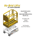
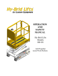
M MAINTE ENAN NCE AN ND TROU UBLE ESHOO OTING G MAN NUAL Hy-Brid Liffts Moodels HB 11030CE E HB11430CE E Self-P Propelledd Aeerial Woork Platfform TableofContents Safety ............................................................................................................................................................ 5 Safety Symbols .......................................................................................................................................... 5 General Rules and Precautions ................................................................................................................. 5 Safety Guidelines ...................................................................................................................................... 6 Maintenance Lock ..................................................................................................................................... 6 Maintenance ................................................................................................................................................. 6 Battery Maintenance ................................................................................................................................ 7 Lubrication ................................................................................................................................................ 8 Components requiring adjustment ........................................................................................................... 9 Examination, repair, replacement of limited life components ................................................................. 9 Safety devices and systems requiring checks ........................................................................................... 9 Storage ...................................................................................................................................................... 9 Major Alterations or Repairs ..................................................................................................................... 9 Other Procedures ...................................................................................................................................... 9 Setting the Tilt Sensor ........................................................................................................................... 9 Voltage Test Points ............................................................................................................................... 9 Stability Testing ............................................................................................................................................. 9 Inspection and Regular Maintenance Checklists ........................................................................................ 10 Monthly Battery Care .............................................................................................................................. 10 Prestart Inspection Checklist .................................................................................................................. 11 Frequent Inspection Checklist ................................................................................................................. 12 Pre‐Delivery/Annual Inspection Checklist ............................................................................................... 13 Technical References .................................................................................................................................. 14 Platform Control Error Display ................................................................................................................ 14 Hydraulic Schematic ................................................................................................................................ 15 Electrical Schematic ................................................................................................................................ 17 Wiring Diagrams .......................................................................................................................................... 19 Wiring Diagram ....................................................................................................................................... 19 Main Power & Safety .............................................................................................................................. 21 SUPO-611E REV F Page 1 of 40 Drive Circuit ............................................................................................................................................. 23 Elevate/Lower Circuit .............................................................................................................................. 25 Troubleshooting .......................................................................................................................................... 27 Troubleshooting Flowchart ..................................................................................................................... 27 Troubleshooting Flowchart—Drive& Steer Circuit ................................................................................. 29 Troubleshooting Flowchart—Elevate & Lower Circuit ........................................................................... 31 Replacement Parts ...................................................................................................................................... 33 Safety and Control Decals ....................................................................................................................... 33 Main Power/Safety Circuit ...................................................................................................................... 34 Drive Circuit Parts ................................................................................................................................... 35 Steer Circuit Parts ................................................................................................................................... 36 Elevate/Lower Circuit Parts ..................................................................................................................... 37 Covers/Other........................................................................................................................................... 39 Warranty ..................................................................................................................................................... 40 Revision Table: Revision A (01/14/2010): Initial Release Revision F (10/24/2012): Revised logos SUPO-611E REV F Page 2 of 40 Drive Circuit ............................................................................................................................................. 23 Elevate/Lower Circuit .............................................................................................................................. 25 Troubleshooting .......................................................................................................................................... 27 Troubleshooting Flowchart ..................................................................................................................... 27 Troubleshooting Flowchart—Drive& Steer Circuit ................................................................................. 29 Troubleshooting Flowchart—Elevate & Lower Circuit ........................................................................... 31 Replacement Parts ...................................................................................................................................... 33 Safety and Control Decals ....................................................................................................................... 33 Main Power/Safety Circuit ...................................................................................................................... 34 Drive Circuit Parts ................................................................................................................................... 35 Steer Circuit Parts ................................................................................................................................... 36 Elevate/Lower Circuit Parts ..................................................................................................................... 37 Covers/Other........................................................................................................................................... 39 Warranty ..................................................................................................................................................... 40 Revision Table: Revision A (01/14/2010): Initial Release Revision B (04/08/2010): Revised Cover, p.33‐38 Part Numbers for replacement parts Revision C (06/15/2010): Revised pages 2, 3, 9‐11, added p.12, revised p. 34: Added stability testing information, revised inspection checklists Revision D (07/21/2010): Revised pages 3, 15, 37‐38 Revision E (11/15/2010): Revised pages 3, 9 SUPO-611E REV F Page 3 of 40 Original instructions are written in English Foreword The purpose of this Maintenance Manual is to provide qualified service personnel with information for servicing and maintaining Hy-Brid Lifts. All information in this manual must be read and understood before any attempt is made to service this machine. The operation and safety manual is considered a part of the work platform and contains instructions and operating procedures essential to properly and safely operate the Custom Equipment Hy-Brid Lift. Users must read and understand all information in the Safety and Operations Manual before operation. DANGER THE OPERATION AND SAFETY MANUAL MUST BE READ AND UNDERSTOOD PRIOR TO OPERATING THE MACHINE. THE USER/OPERATOR SHOULD NOT ACCEPT OPERATING RESPONSIBILITY UNTIL THE MANUAL HAS BEEN READ AND UNDERSTOOD AS WELL AS HAVING OPERATED THE LIFT UNDER SUPERVISION OF AN EXPERIENCED AND QUALIFIED OPERATOR. BECAUSE THE MANUFACTURER HAS NO DIRECT CONTROL OVER MACHINE APPLICATION AND OPERATION, PROPER SAFETY PRACTICES ARE THE RESPONSIBILITY OF THE USER AND ALL OPERATING PERSONNEL. WARNING ANY MODIFICATION ON THIS MACHINE WITHOUT THE EXPRESS WRITTEN CONSENT OF THE MANUFACTURER IS PROHIBITED. If there is a question on application and/or operation, contact: Custom Equipment, Inc. 2647 Hwy 175 Richfield, WI 53076 USA Phone: 262-644-1300 Fax: 262-644-1320 www.hybridlifts.com SUPO-611E REV F Page 4 of 40 Safety Safety Symbols DANGER FAILURE TO FOLLOW THIS WARNING WILL CAUSE DEATH OR PERSONAL INJURY. WARNING FAILURE TO FOLLOW THIS WARNING MAY CAUSE DEATH OR PERSONAL INJURY. "DANGER" indicates an imminently hazardous situation, which, if not avoided, will result in death or serious injury. "WARNING" indicates a potentially hazardous situation, which, if not avoided, could result in death or serious injury "CAUTION" indicates a potentially hazardous situation which, if not avoided, could result in FAILURE TO FOLLOW THIS WARNING minor or moderate injury or damage to MAY CAUSE INJURY OR DAMAGE EQUIPMENT equipment CAUTION General Rules and Precautions Custom Equipment, Inc. designed the Hy‐Brid Lift self‐propelled scissor lift to be safe and reliable. It is intended for elevating personnel, along with their necessary tools and materials to overhead work locations. Vibration does not create significant hazards on this machine. An operator of any type of work platform is subject to certain hazards that cannot be protected by mechanical means. It is therefore essential that operators be competent, careful, physically and mentally fit and thoroughly trained in safe operation of this machine. Although Custom Equipment, Inc. conforms to specified EN: 280 requirements, it is the responsibility of the owner to instruct operators with the safety requirements made not only by Custom Equipment, Inc., but by the various safety boards in your area, as well as additional requirements set forth by EN: 280 If you come across a situation that you think might be unsafe, stop the platform and request further information from qualified sources before proceeding. WARNING MAINTENANCE INFORMATION IS FOR USE BY TRAINED PERSONNEL ONLY WARNING NEVER REACH BETWEEN SCISSORS LINKS OR PROP UP PLATFORM UNLESS MAINTENANCE PINS ARE IN PLACE. SUPO-611E REV F Page 5 of 40 Safety Guidelines Maintenance Lock The maintenance lock must be placed into position whenever the machine is being serviced in the raised or partially raised position. Serious injury and/or death could result if maintenance lock is not used properly. Maintenance Pin Location When in Use Figure 1: Maintenance Lock Pin Use Pin Storage Location Figure 2: Maintenance Lock Pin Storage Maintenance WARNING • • • • • • • • • • FAILURE TO COMPLY WITH THE LISTED SAFETY PRECAUTIONS MAY RESULT IN MACHINE DAMAGE, PERSONNEL INJURY OR DEATH. Never work under an elevated platform until maintenance locks have been engaged. Remove all rings, watches, and jewelry when performing any maintenance. Do not wear long hair unrestrained or loose fitting clothing and neckties which may become caught on or entangled in equipment. Observe and obey all warnings and cautions on machine and in manual. Keep oil, grease, water, etc. wiped from standing surfaces and handholds. Before making any adjustments, lubricating or performing any other maintenance, shut off all power controls. Battery should always be disconnected during replacement of electrical components. Keep all support equipment and attachments stowed in their proper place. Use only approved nonflammable cleaning solvents. After maintenance, inspect the machine as described for Pre-delivery. SUPO-611E REV F Page 6 of 40 FFigure 4: Batteryy Charger LED Diisplay This dispplay indicatess that power iis on but ther e is no conneection to a battery. The charrger must seee approximateely 5 volts on a battery to d deliver d/c cu urrent. This di splay indicatees that power is utputs are on andd that both ou deliverring d/c curreent to the batteriies. This di splay indicatees that power is on and th at both outputs are finished charginng and are in a float mainttenance mode. WA ARNING G DO NOT OPERATE O UNIT WHILE CHARGING G. DO NOT DISABLE D CH HARGER INTERLOCK. CAUTION N NEVE ER ADD ACID D TO BATTERY! TThe solution is at its proper strength wh hen the batte ery is manufacctured. Use d distilled wateer and keep fluid up to p proper level. When requirred, water sho ould be added to battery aafter chargingg, unless wateer level is below the p plates. L Lubrication n Ittem FFront Wheels LLower Slider B Block Channel Specification S Teflon Spray T Teflon Spray T FFrequency of Lubrication Q Quarterly A As needed to prevent chattter when fullyy loaded SUPO-611E REV F Page 7 of 40 Figure 4: Battery Charger LED Display 50% 75% 100% GEL Charger LED Display Charging State 0 to 50% charged Blinking Off Off NA 50% to 75% charged On Blinking Off NA 75% to 100% charged On On Blinking NA 100% charged On On On NA Charge for flooded type batteries NA NA NA Off Charge for Sealed type batteries NA NA NA On Abnormal Cycle Off Off Blinking NA WARNING DO NOT OPERATE UNIT WHILE CHARGING. DO NOT DISABLE CHARGER INTERLOCK. CAUTION NEVER ADD ACID TO BATTERY! The solution is at its proper strength when the battery is manufactured. Use distilled water and keep fluid up to proper level. When required, water should be added to battery after charging, unless water level is below the plates. Lubrication Item Front Wheels Lower Slider Block Channel Specification Teflon Spray Teflon Spray Frequency of Lubrication Quarterly As needed to prevent chatter when fully loaded SUPO-611E REV F Page 8 of 40 Components requiring adjustment Under normal use, no components should require adjustment. Contact the manufacturer if adjustments are required. Examination, repair, replacement of limited life components With proper use, battery maintenance, and regular inspection, there are no limited life components that require routine replacement. Safety devices and systems requiring checks Check safety functions as part of daily inspection. Check that the electromagnetic brakes are holding. Storage After periods of storage, exposure to extremes of ambient conditions‐heat, cold, moisture, dust etc. inspect the machine. Refer to the Pre‐Delivery/ Frequent Inspection Checklist in the Maintenance Manual. Major Alterations or Repairs Any alterations must be approved by the manufacturer. Major repairs, which affect the stability, strength, or performance of the machine must also be approved by the manufacturer, recorded, and include machine inspection and testing. Never attach pipe racks, material lifting devices, or make any other alteration that is not part of the intended design of the machine. Other Procedures Setting the Tilt Sensor 1. Verify that unit is powered (red or green LED illuminated/blinking). 2. Zero unit (teach unit home/level position). a. Operate tilt platform until it has reached the desired home position (level). b. Press and hold the button on top of the module for 5 seconds (both LEDs will be OFF). c. Red and Green LEDs will now FLASH. User now has 5 seconds to “program” d. Press and release button 3 times within 5 second period. e. Red and Green LEDs will turn on solid for 2 seconds, indicating position is being learned. Voltage Test Points Contact technical assistance for more detail. Stability Testing The HB1430CE & HB1030CE have been stability tested to standards EN280 or AS 14180. The most adverse stability test is the stationary, lateral slope configuration for both units. The overturning moment created by the test loads and forces is equivalent to a test on an unloaded machine on a level surface, as shown in the figure below. For the HB1030CE, the test weight/pull force is 52 kg/115 lb. For the HB1430CE, the test weight is 55.3 kg/122 lb. Figure 5: Stability Test, Equivalent SUPO-611E REV F Page 9 of 40 Inspection and Regular Maintenance Checklists CAUTION FAILURE TO PERFORM INSPECTIONS AND PREVENTITIVE MAINTENANCE AT RECOMMENDED INTERVALS MAY RESULT IN THE UNIT BEING OPERATED WITH A DEFECT THAT MAY RESULT IN INJURY OR DEATH OF THE OPERATOR. Regular inspection and conscientious maintenance is important to efficient economical operation of this machine. It will help to assure that equipment will perform satisfactorily with a minimum of service and repair. Make checks at the stated intervals or more frequently if required by local operating conditions. The following inspection checklists are required and included in this manual: Pre‐Start (Required before operation at each work shift) Monthly Battery Maintenance Frequent (Required at intervals not more than three months) Pre‐Delivery/Annual (Required at intervals not more than twelve months) The rated life of the machine is Light Intermittent Duty (typical use 10 years, 40 weeks per year, 20h per week, 5 load cycles per h). Monthly Battery Care WARNING THIS CHECKLIST MUST BE USED AT MONTHLY OR AFTER EVERY 100 HOURS OF USE. FAILURE TO DO SO COULD AFFECT THE SAFETY OF THE OPERATOR. MODEL NUMBER _____________ SERIAL NUMBER ______________ 1. 2. 3. Keep inspection records up‐to‐date. Record and report all discrepancies to your supervisor. A dirty machine cannot be properly inspected. Y‐Yes/Acceptable N‐No/Unacceptable R‐Repaired Description Y N R Monthly Battery Care: 1. Remove battery cabinet cover. 2. Remove battery caps and check fluid level. 3. Fill each cell (if needed) to split ring with distilled water. 4. Reinstall caps. 5. Wash all dirt, debris, acid, etc., off battery whenever corrosion is detected. Use a solution of 5‐tsp. baking soda per quart of warm water. 6. Coat terminals with a commercially available coating. DATE _______________ INSPECTED BY ____________________________ SUPO-611E REV F Page 10 of 40 Prestart Inspection Checklist WARNING THIS CHECKLIST MUST BE USED AT THE BEGINNING OF EACH SHIFT OR AFTER EVERY SIX TO EIGHT HOURS OF USE. FAILURE TO DO SO COULD AFFECT THE SAFETY OF THE OPERATOR. MODEL NUMBER ______________ SERIAL NUMBER ______________ 1. 2. 3. Keep inspection records up-to-date. Record and report all discrepancies to your supervisor. A dirty machine cannot be properly inspected. Y-Yes/Acceptable N-No/Unacceptable R-Repaired Description Y N R Visual Inspections Check that there are no damaged, dented, or bent structural members. There are no loose or missing parts. Check that warning and instructional labels are legible and secure. Ensure that load capacity is clearly marked. Check the platform rails and safety gate for damage. Platform and base controls are not missing, damaged, or disconnected. Electrical cables and wires are not torn, frayed, or disconnected. Hydraulic hoses are not torn or loose, and there are no leaks. Check that hoses and the cables have no worn areas or chafing. Check the hydraulic fluid level with the platform fully lowered. Check the tires for damage. Check that wheel axle retaining rings and set screw in rear wheel are tight. Check that all snap rings are secure in grooves on pivot pins. Functional Tests Gate closes automatically and latches (alignment can be adjusted with screw on toe board or railing if necessary). Platform Controls: Check all switches and push buttons for proper operation. Emergency Stop (Stops all movement) Drive/Steer & Up/Down Mode Button (Selects drive/steer or elevate mode) Joystick & Thumb Rocker Switch (Return to neutral, drives forward & reverse, elevates & lowers) Drive Enable Trigger (Must be activated to drive) Horn Diagnostic Display (Displays tilt, overload) Base Controls: Check all switches and push buttons for proper operation. Emergency Stop (Stops all movement) Key Switch (Selects Platform Control, Ground Control, or Off) Up/Down Rocker Switch (Elevates, Lowers) Alarm (Not damaged, sounds for descent, overload) LED (Flashes when overloaded) Wheels: Front and rear wheels rotate freely. Drives in slow speed when elevated. Brakes: Machine stops when joystick released. Pothole guards deploy and lock when platform is raised. Lift does not elevate when pothole guards are blocked. DATE _______________ INSPECTED BY ____________________________ SUPO-611E REV F Page 11 of 40 Frequent Inspection Checklist WARNING AERIAL PLATFORMS SHALL BE INSPECTED, SERVICED AND ADJUSTED TO MANUFACTURER'S REQUIREMENTS BY A QUALIFIED MECHANIC PRIOR TO EACH SALE, LEASE, OR RENTAL, AND EVERY 3 MONTHS OR 150 HOURS, WHICHEVER COMES FIRST. MODEL NUMBER ___________ SERIAL NUMBER ______________ • • • • Check each item listed below. Use proper operating, service, and maintenance manual for specific information and settings If an item is found to be unacceptable make the necessary repairs and check the “repaired” box. When all items are “acceptable”, the unit is ready for service. Description Visual Inspections Perform all checks on the Pre‐Start Inspection Checklist. Inspect the condition of hydraulic fluid in reservoir. Oil should have a clear amber color. Inspect the entire machine for signs of damage, broken welds, loose bolts, or improper repairs. (Check for corrosion, cracking, abrasion, etc.) Check that all snap rings are secure in grooves on pivot pins. Check if tires are leaning in or out. Check electrical motor brushes (every 150 hours) Verify that maintenance and inspection records are up to date. Functional Tests Perform all checks on the Pre‐Start Inspection Checklist. Functions operate smoothly. Functions operate over full range of motion. Elevated and Lowered drive speeds do not exceed specifications listed in Operators manual. Emergency Lowering—Manual override functions properly. Ground Controls override platform controls. Check that the platform does not drift down with a full load. Wheels lubricated if needed. Comments: DATE _______________ INSPECTED BY _______________________________ SUPO-611E REV F Y N R Page 12 of 40 PreDelivery/Annual Inspection Checklist WARNING AERIAL PLATFORMS SHALL BE INSPECTED, SERVICED AND ADJUSTED TO MANUFACTURER'S REQUIREMENTS BY A QUALIFIED MECHANIC PRIOR TO EACH SALE, LEASE, OR RENTAL, AND EVERY 12 MONTHS. MODEL NUMBER: HB1030CE or HB1430CE SERIAL NUMBER ______________ • • • • Check each item listed below. Use proper operating, service, and maintenance manual for specific information and settings If an item is found to be unacceptable make the necessary repairs and check the “repaired” box. When all items are “acceptable”, the unit is ready for service. Check Y N R Base: Inspect slide tracks for damage Steering actuator pinned All frame bolts tight Pump Secure Tie Rod secure DC motor secure Battery Hold Downs Secure Batteries Fully Charged Counterweights secured Wheels: Snap Rings Secure Wheels: Bolts/Nuts Tight Maintenance Locks: Pins in cabinet All Shields/Guards in place Hydraulic Oil Level 1” from top Check all hydraulic hoses for leaks Check all hydraulic fittings for leaks Scissors: Broken Welds Bent Beam Members All rollers Turn Freely Ret. Rings Secure On Pivots Broken welds Platform: All rails in place/secure No bent rails No broken welds 110V outlet safe/working (if installed) Entrance gate Closes Freely Operator/Service Manual Included Cables in place/secure Extending platform extends freely Extending platform Locks in Stowed Position Extending platform Locks in Extended Position Check Y N R Decals: Legibility Correct capacity noted Proper placement quantity Wiring: Switches secure Contactor(s) secure Tight on terminals (No loose wiring) Functions: Drive, Lift, Steer Functioins Operational Emergency Stop Breaks Circuits Slow Speed limit switch Set properly Emergency Down Operational Pothole guards deploy when platform Pothole interlock functions correctly Brakes: Operational Tilt sensor Functional Warning Horn Alarms Motion Alarms Functional Hour meter operational Battery indication operational Verify Overload Calibration Battery Charger Secure/Operational Comments: DATE _______________ INSPECTED BY _______________________________ SUPO-611E REV F Page 13 of 40 Technical References Platform Control Error Display Display Description 01 System initialization error 02 System communication error 03 Invalid option setting 11 Free wheel switch on motor is open 12 Chassis Up or Down ON at power‐up 18 Pothole guard error 31 Pressure Sensor Fault 32 Angle Sensor Fault 42 Platform Left Turn Switch ON at power‐up 43 Platform Right Turn Switch ON at power‐up 46 Platform Joystick Enable Switch ON at power‐up 47 Platform Joystick not in neutral at power‐up 54 Lift Up Coil Fault 55 Lift Down Coil Fault 58 Brake Fault 60 Motor Fault 61 Motor Controller Fault 62 Temperature Fault 63 Charger Fault 64 Motor Controller Fault 68 Low Voltage Fault 80 Over 80% Load 90 Over 90% Load 99 Over 100% Load OL Overloaded Platform LL Machine Tilted beyond safe limits Platform Control Battery Monitor Display Battery Percent Description ‐ ‐ 90 Percent of Battery Charge ‐ ‐ ‐ ‐ ‐ ‐ ‐ ‐ ‐ ‐ ‐ ‐ ‐ ‐ ‐ ‐ ‐ ‐ 70 Percent of Battery Charge 50 Percent of Battery Charge 30 Percent of Battery Charge 20 Charge Battery 10 Very Low Charge ‐ SUPO-611E REV F Page 14 of 40 SUPO-611E REV F Page 15 of 40 This page intentionally left blank. SUPO-611E REV F Page 16 of 40 SUPO-611E REV F Page 17 of 40 SUPO-611E REV F Page 18 of 40 SUPO-611E REV F Page 19 of 40 SUPO-611E REV F Page 20 of 40 SUPO-611E REV F Page 21 of 40 SUPO-611E REV F Page 22 of 40 SUPO-611E REV F Page 23 of 40 SUPO-611E REV F Page 24 of 40 SUPO-611E REV F Page 25 of 40 SUPO-611E REV F Page 26 of 40 Does the machine have any function: (Drive, Steer Elevate/Lower) Yes, but some function(s) are not working properly No Are the batteries connected? Check per wiring diagram. Yes Connect batteries. See wiring diagram & battery connection sequence. Is master disconnect switch open? Yes Is key switch turned on? Yes Are both E-Stop buttons off? Yes Is Upper Control plugged in? Yes Is charger plugged in? No No No No Yes Close Switch. Turn key switch on Reset E-Stop buttons. Pull out at both upper control and lower control locations. Connect Upper Control box. Unplug charger. Unit will not operate while charging. Does Platform Control Display a Fault Code? No Are the batteries fully charged? Yes Is short protection fuse at pump blown? Yes Is unit overloaded? No Check Component or Condition Referenced by Fault Code No Yes Yes (Check voltmeter at lower control or check voltage across battery terminals using voltmeter/multi-meter) Charge batteries. Replace Fuse Remove load. Safety function activated. If batteries do not take charge Replace batteries Or Replace charger (Load test batteries, individually, disconnected from machine) See Drive & Steer Problems Flowchart Check for loose wiring connections. Check for ground connection at pump. See wiring diagrams. Check for continuity in connections use Voltmeter/ Multi-meter at 400V setting. Still no functions? Contact CEI for further troubleshooting Consider Signet charger failure (interlock contacts) See Elevating & Lowering Problems Flowcharts Is there a different problem? Contact CEI for further troubleshooting SUPO-611E Hy-Brid Troubleshooting Flowchart Revision A: Initial Release 01/14/2010 SUPO-611E REV F Page 27 of 40 Does the machine have any function: (Drive, Steer Elevate/Lower) Yes, but some function(s) are not working properly No Are the batteries connected? Check per wiring diagram. Yes Connect batteries. See wiring diagram & battery connection sequence. Is master disconnect switch open? Yes Is key switch turned on? Yes Are both E-Stop buttons off? Yes Is Upper Control plugged in? Yes Is charger plugged in? No No No No Yes Close Switch. Turn key switch on Reset E-Stop buttons. Pull out at both upper control and lower control locations. Connect Upper Control box. Unplug charger. Unit will not operate while charging. Does Platform Control Display a Fault Code? No Are the batteries fully charged? Yes Is short protection fuse at pump blown? Yes Is unit overloaded? No Check Component or Condition Referenced by Fault Code No Yes Yes (Check voltmeter at lower control or check voltage across battery terminals using voltmeter/multi-meter) Charge batteries. Replace Fuse Remove load. Safety function activated. If batteries do not take charge Replace batteries Or Replace charger (Load test batteries, individually, disconnected from machine) See Drive & Steer Problems Flowchart Check for loose wiring connections. Check for ground connection at pump. See wiring diagrams. Check for continuity in connections use Voltmeter/ Multi-meter at 400V setting. Still no functions? Contact CEI for further troubleshooting Consider Signet charger failure (interlock contacts) See Elevating & Lowering Problems Flowcharts Is there a different problem? Contact CEI for further troubleshooting SUPO-611E Hy-Brid Troubleshooting Flowchart Revision A: Initial Release 01/14/2010 SUPO-611E REV F Page 28 of 40 Does the machine drive? (Elevate, Lower OK) Is either or two brakes manually released? No Is either of two brake switches damaged or disconnected? No Yes Yes Flip brake handle(s) at rear of machine to engage brakes. Replace brake switch. Note that brake limit switch tabs are delicate. Use caution not to break off. Is drive unit damaged? Are all connections to drive control board secure? No Yes Is there moisture or corrosion in any connections? Yes No No Yes Reconnect Allow to dry for 24 hours and try again. Board probably will need replacement. Apply dielectric grease to connectors at main wire harness. Replace drive control board Still no drive? Yes, but not properly Check connections at both pump and board. See wiring diagrams. Driving slowly? Drives slow when lowered? Drives fast when elevated? Are batteries fully charged? No Is mode limit switch damaged or blocked with debris? Do pothole guards and lock deploy properly? Replace drive unit Yes Contact CEI for further troubleshooting. Consider brake damage, broken joystick handle (drive enable), bad hour meter, loose connections in lower and upper control Charge Batteries Yes Is mode limit switch damaged or blocked with debris? Clean any debris from limit switch area. Check for proper connection inside limit switch. (See wiring diagram). Replace mode limit switch. Contact CEI for further troubleshooting. Consider board failure or incorrect wiring. Clean any debris from limit switch area. Check for proper connection inside limit switch. (See wiring diagram). Replace mode limit switch. Yes Contact CEI for further troubleshooting. Consider board failure or loose wiring. Clean any debris from pothole arm mechanism SUPO-611E REV F Does not drive when elevated? Is machine tilted? (Tilt sensor will be beeping, but functions should not be disabled) Is machine overloaded? (Safety feature stops all function if overloaded) Drives intermittently? Check wiring connection integrity. Is there moisture or corrosion in any connections? Does not Steer? Consider relay failure, relay block wiring. Check wire connections at actuator. Pull test connections—if failure, crimp on new connector(s) Page 29 of 40 Remove load. Contact CEI for further troubleshooting. Consider board failure, pothole interlock limit switch failure, control module failure failure, disconnected, damaged, or failed height transducer. Air dry all connections and try again. Board probably will need replacement. Apply dielectric grease to connectors at cable. Check steer actuator for failure. Apply 24V to actuator leads. Contact CEI for further troubleshooting. Consider board failure Check joystick thumb switch SUPO-611E Hy-Brid Troubleshooting Flowchart Drive & Steer Problems Revision A: Initial Release 01/14/2010 Does the machine drive? (Elevate, Lower OK) Is either or two brakes manually released? No Is either of two brake switches damaged or disconnected? No Yes Yes Flip brake handle(s) at rear of machine to engage brakes. Replace brake switch. Note that brake limit switch tabs are delicate. Use caution not to break off. Is drive unit damaged? Are all connections to drive control board secure? No Yes Is there moisture or corrosion in any connections? Yes No No Yes Reconnect Allow to dry for 24 hours and try again. Board probably will need replacement. Apply dielectric grease to connectors at main wire harness. Replace drive control board Still no drive? Yes, but not properly Check connections at both pump and board. See wiring diagrams. Driving slowly? Drives slow when lowered? Drives fast when elevated? Are batteries fully charged? No Is mode limit switch damaged or blocked with debris? Do pothole guards and lock deploy properly? Replace drive unit Yes Contact CEI for further troubleshooting. Consider brake damage, broken joystick handle (drive enable), bad hour meter, loose connections in lower and upper control Charge Batteries Yes Is mode limit switch damaged or blocked with debris? Clean any debris from limit switch area. Check for proper connection inside limit switch. (See wiring diagram). Replace mode limit switch. Contact CEI for further troubleshooting. Consider board failure or incorrect wiring. Clean any debris from limit switch area. Check for proper connection inside limit switch. (See wiring diagram). Replace mode limit switch. Yes Contact CEI for further troubleshooting. Consider board failure or loose wiring. Clean any debris from pothole arm mechanism Does not drive when elevated? Is machine tilted? (Tilt sensor will be beeping, but functions should not be disabled) Is machine overloaded? (Safety feature stops all function if overloaded) Drives intermittently? Check wiring connection integrity. Is there moisture or corrosion in any connections? Does not Steer? Consider relay failure, relay block wiring. Check wire connections at actuator. Pull test connections—if failure, crimp on new connector(s) Remove load. Contact CEI for further troubleshooting. Consider board failure, pothole interlock limit switch failure, control module failure failure, disconnected, damaged, or failed height transducer. Air dry all connections and try again. Board probably will need replacement. Apply dielectric grease to connectors at cable. Check steer actuator for failure. Apply 24V to actuator leads. SUPO-611E REV F Contact CEI for further troubleshooting. Consider board failure Check joystick thumb switch SUPO-611E Hy-Brid Troubleshooting Flowchart Drive & Steer Problems Revision A: Initial Release 01/14/2010 Page 30 of 40 Does machine raise/ lower? No Does pump operate? Is emergency down valve open? Yes Is hydraulic fluid low? Is down valve stuck open? Is up/down switch damaged? With platform lowered, fill pump reservoir to 1" below top of reservoir Flush valve by simultaneously pressing up switch at base and down switch on platform control for 30 sec. Replace rocker switch at upper or lower control. Contact CEI for further troubleshooting. No Check for power connection. See Hy-Brid Troubleshooting Is power solenoid damaged? Yes, but not properly Close emergency down valve or cable connections Replace solenoid. Are diodes functioning properly? Measure resistance across diode—Ohm meter/multi-meter at 40 kΩ setting. With black lad on stripe side and red on other side, should get a resistance reading. Switch leads, no reading. Replace bad diode. Replace pump assembly Ascent speed slow or erratic? Starts elevating, then stops? Are any structural members bent? Is battery fully charged? Contact manufacturer to arrange replacement. Charge battery. Are pothole guards blocked? Is pothole limit switch functionning? Is emergency down valve open? Is there a restriction in hydraulic hose? Close emergency down valve. Replace hydraulic hose. Flush down valve by simultaneously pressing up switch at base and down switch on platform control for 30 sec. There may be foreign matter lodged. Check integrity of electrical connections, There may be a loose connection or momentary short. Replace pump. May be worn or defective. Replace limit switch or repair connections. Remove obstruction. Will not descend? Creeps down? Has key switch been turned off? Is an E-Stop activated? Is battery charged? Turn key to on position. Pull out emergency stop button at upper and lower controls. Charge batteries. Is emergency down valve open? Foreign matter lodged in up or down valve? Faulty down valve? Disassemble and clean. Look for residue in screen and on O-ring or damage to O-ring. Close emergency down valve. Check cable connections. SUPO-611E REV F Electrical problem? Disconnect coil. Check if unit stops drifting. Check voltage at coil—should be 0 V when not energized. Replace down valve. Page 31 of 40 Replace down solenoid. Damaged cylinder or damaged seal in cylinder? Check for loose electrical connections. Coil mounting nut too tight? Nut should only be lightly snug: 30 in.-lb. Replace coil and lightly tighten nut. Run unit up and then check for oil flow out of return line. Bad cylinder seal if oil is flowing from return line. Might be able to repair with seal kit;, probably need to replace cylinder. If walls inside cylinder are scratched or pitted, cylinder needs replacement. Faulty check valve in pump? Listen carefully near motor when not energized—may be running backwards. Replace pump SUPO-611e Hy-Brid Troubleshooting Flowchart Elevate & Lower Problems Revision A: Initial Release 01/14/2010 Does machine raise/ lower? No Does pump operate? Is emergency down valve open? Yes Is hydraulic fluid low? Is down valve stuck open? Is up/down switch damaged? With platform lowered, fill pump reservoir to 1" below top of reservoir Flush valve by simultaneously pressing up switch at base and down switch on platform control for 30 sec. Replace rocker switch at upper or lower control. Contact CEI for further troubleshooting. No Check for power connection. See Hy-Brid Troubleshooting Is power solenoid damaged? Yes, but not properly Close emergency down valve or cable connections Replace solenoid. Are diodes functioning properly? Measure resistance across diode—Ohm meter/multi-meter at 40 kΩ setting. With black lad on stripe side and red on other side, should get a resistance reading. Switch leads, no reading. Replace bad diode. Replace pump assembly Ascent speed slow or erratic? Starts elevating, then stops? Are any structural members bent? Is battery fully charged? Contact manufacturer to arrange replacement. Charge battery. Are pothole guards blocked? Is pothole limit switch functionning? Is emergency down valve open? Is there a restriction in hydraulic hose? Close emergency down valve. Replace hydraulic hose. Flush down valve by simultaneously pressing up switch at base and down switch on platform control for 30 sec. There may be foreign matter lodged. Check integrity of electrical connections, There may be a loose connection or momentary short. Replace pump. May be worn or defective. Replace limit switch or repair connections. Remove obstruction. Will not descend? Creeps down? Has key switch been turned off? Is an E-Stop activated? Is battery charged? Turn key to on position. Pull out emergency stop button at upper and lower controls. Charge batteries. Is emergency down valve open? Foreign matter lodged in up or down valve? Faulty down valve? Disassemble and clean. Look for residue in screen and on O-ring or damage to O-ring. Close emergency down valve. Check cable connections. Electrical problem? Replace down solenoid. Damaged cylinder or damaged seal in cylinder? Disconnect coil. Check if unit stops drifting. Check voltage at coil—should be 0 V when not energized. Replace down valve. Check for loose electrical connections. Coil mounting nut too tight? Nut should only be lightly snug: 30 in.-lb. Replace coil and lightly tighten nut. Run unit up and then check for oil flow out of return line. Bad cylinder seal if oil is flowing from return line. Might be able to repair with seal kit;, probably need to replace cylinder. If walls inside cylinder are scratched or pitted, cylinder needs replacement. SUPO-611E REV F Faulty check valve in pump? Listen carefully near motor when not energized—may be running backwards. Replace pump SUPO-611e Hy-Brid Troubleshooting Flowchart Elevate & Lower Problems Revision A: Initial Release 01/14/2010 Page 32 of 40 Replacement Parts CAUTION USE ONLY MANUFACTURER APPROVED REPLACEMENT PARTS. USE OF NON‐OEM PARTS WILL VOID WARRANTY. DANGER REPLACEMENT OF THE FOLLOWING COMPONENTS WILL AFFECT THE STRENGTH, STABILITY, OR SAFETY FUNCTION OF THE UNIT: BATTERY (ELEC‐047), HYDRAULIC CYLINDER (HYDR‐007‐1 OR HYDR‐041‐2), DRIVE CONTROL BOARD (ELEC‐903), AND ALL STRUCTURAL COMPONENTS. Listed below are replacement parts that may be available and listed for reference. These represent current revisions. Refer to our website, www.hybridlifts.com for more complete part listings and earlier revisions. Several parts are model, serial number, or manufacture date specific. Contact your dealer for replacement part availability and pricing. Safety and Control Decals Refer to Operator’s Manual for decal part numbers and locations. SUPO-611E REV F Page 33 of 40 MainPo ower/Safety yCircuit Item # 1 2 3 4 Batte ery Batte ery Tray Batte ery Strap 5 Mastter Power Swittch 6 Tilt SSensor Part ## NA ELEC‐‐670‐2 NA (ELEC C‐047) HB‐00001‐P HARD D‐054 ELEC‐‐633‐KIT ELEC‐‐633‐1 ELEC‐‐829 7 Batte ery Charger ELEC‐‐747 8 9 10 Conttrol Module Emergency Stop Sw witch Tilt A Alarm Key SSwitch Sparre Key Main n Wire Harnesss Emergency Stop Sw witch Joysttick Conttrol Module, Upper Uppe er Control Asse embly Lowe er Control Asse embly Batte ery Charger Co ord Batte ery Cables SUBA A8350E ELEC‐‐071‐KIT ELEC‐‐635‐2 ELEC‐‐073E ELEC‐‐073EKEY SUB A A13006E ELEC‐‐071‐KIT ELEC‐‐601‐100 SUB A A9350E SUBA A9003E SUB A A8003E ELEC‐‐639‐11 ELEC‐‐641‐100 & 10 002101650 11 12 13 14 15 16 17 (Not Picture ed) (Not Picture ed) SUPO-611E REV F Desccription B+ P Power Connecction Location n on Pump Fuse e B‐“G Ground” Conn nection Locattion on Pump Page 34 of 40 Drive Circuit Parts Item # 1 2 3 4 5 6 7 8 9 10 SUPO-611E REV F Part # ELEC‐626‐3R ELEC‐627‐4 ELEC‐627‐3R ELEC‐627‐3L SUBA9003E ELEC‐626‐3L WHEE‐600‐1 SUBA8350E SUB 904 ELEC‐610‐1 Description Electric Drive Motor (Right/Control Side) Brake Micro switch Brake (Left) Brake (Right) Platform Control Assembly Electric Drive Motor (Left/Control Side) 10” x 4” Wheel Base Control Module Drive Control Board (specific to this model/series only) Hour Meter Page 35 of 40 Steer Circuit Parts Item # 1 2 3 4 5 6 7 8 9 10 11 (Not Pictured) SUPO-611E REV F Part # HB‐ST‐2‐A‐P PB‐0018‐P HB‐ST‐4‐B‐PC PB‐0021‐P HB‐ST‐3‐A‐P SUB A9003E SUBA8350E SUB A29‐KIT ELEC‐631 ELEC‐624 WHEE‐604 (No Part #) Description Tie Rod‐Long Center Steer Pin Center Steer Weldment Caster Tie Rod‐Short Platform Controls Assembly Lower Control Module Steer Actuator Assembly Relay Limit Switch 10” X 2” WHEEL 7A ACG Fuse Page 36 of 40 Elevate/Lower Circuit Parts SUPO-611E REV F Page 37 of 40 Item # 1 2 (Not Pictured) 3 4 5 6 7 8 (Not Pictured) 9 10 11 12 13 14 15 16 17 18 19 20 21 22 23 24 25 26 27 28 29 30 31 32 33 SUPO-611E REV F Part # HB‐PH‐21‐R‐PC HYDR‐050‐1E (HYDR‐032) Description HB2‐Pothole Bar‐R (For 10” Front Wheel Models) Hydraulic Pump Hydraulic Fluid Not available as a replacement part. Replace with Flomite #150, Dexron II, Mobil‐DTE 2, or equivalent. HB‐ML‐P Maintenance Lock Pin (Varies by Model) 1022100450 Hydraulic Cylinder (For 10’ Models) 1022100550 Hydraulic Cylinder (For 14’ Models) ELEC‐647 Angle Transducer HARD‐644 E‐Down Cable (1430) HARD‐644‐01 E‐Down Cable (1030) ELEC‐829 Tilt Sensor SUB A8305E Lower Control Module ELEC‐635‐2 Beeper HB‐PH‐21‐L‐PC HB2‐Pothole Bar‐L (For 10” Front Wheel Models) ELEC‐071‐KIT E‐Stop ELEC‐133B Rocker Switch HYDR‐665 Up Valve HYDR‐664 18V Coil 1020100201 Pump Mount Plate HYDR‐666 24V Solenoid HYDR‐044‐FL3 Hirschmann Connector w/suppression Diode LAS‐M115 E‐Down Valve Actuator WHEE‐605 Spacer HARD‐650 1/16 Shaft Collar HYDR‐007‐2E Down Valve & Coil (Varies by Model) Hydraulic Hose HYDR‐600 or HYDR‐600‐6 HYDR‐626 Flow Control SUBA003E Upper Control Assembly HB‐PH‐7‐P PH Lock Weldment LAS‐M220‐P Pothole Arm ELEC‐623‐2 Limit Switch LAS‐M222‐P Limit Switch Plate ELEC‐623‐2 Limit Switch 1000105902 PH Pick‐Up Arm HB‐PH‐13 Guide Block HB‐PH‐20 Pothole Guard Actuator HARD‐072 Spring ELEC‐648 Pressure Transducer Page 38 of 40 Covers/Other Item # 1 2 3 4 5 6 7 SUPO-611E REV F Part # LAS‐M231‐PC LAS‐M246‐PC LAS‐M230‐PC LAS‐M226‐PC HARD‐633B HARD‐633C or HARD‐633E SUB A8003E Description Cover, Front Cover, Pump Side Cover, Rear Cover, Battery, Control Side Cabinet Latch Handle Cabinet Latch Cam Lower Control Assembly Page 39 of 40 Warranty LIMITED WARRANTY – Warranty Statement --Outside North America Custom Equipment, Inc. (the “Company”) warrants that all new units of equipment manufactured and sold by it conform to the Company’s latest published specifications. Also, that all purchased components and sub-assembled parts and assemblies shall be free from defect in material and/or workmanship for a period of 24 months from the date a new unit is placed into service, with the exception of batteries which are covered by the battery manufacturer for a period of ninety (90) days (pro-rated for one (1) year) on batteries. Further, that all structural components manufactured, purchased, and installed by Custom Equipment, Inc. shall be free of any defect in material and/or workmanship for a period of 60 months from the date a new unit is placed into service. If the equipment owner/end-user experiences a failure or deficiency within the specified warranty period they must promptly notify an authorized Dealer service repair facility. Custom Equipment’s warranty policy requires that ALL warranty claims parts be held for inspection for up to six months or returned to us in a timely fashion if requested. Parts will be requested when we will be returning these parts to our vendor fore credit. During the Warranty period, Custom Equipment, Inc. reserves the right to replace, repair, exchange, or to provide a new, used, or rebuilt component, assembly, sub-assembly, or weldment at their discretion, dependent upon circumstance, situation, and/or availability. For battery warranty, call the number listed on the battery for further instructions. This Warranty Policy does NOT cover damage caused by; shipment, misuse of unit (includes operation beyond Factory established limits, loads, and/or specifications), failure to properly service and maintain the unit in accordance with the Company’s manuals or Factory Service Bulletins. Custom Equipment, Inc. DOES NOT accept any responsibility for alterations or modifications to the unit, or, damages caused by any natural disasters (such as fire, flood, wind and lightning). THE PREVIOUS WARRANTY STATEMENT IS IN LIEU OF ALL OTHER WARRANTIES, EXPRESS OR IMPLIED, INCLUDING BUT NOT LIMITED TO THE IMPLIED WARRANTIES OF MERCHANTABILITY AND FITNESS FOR A PARTICULAR PURPOSE. In no event shall the Company be liable for any indirect, incidental, consequential, or special damage (including without limitation to loss of profits, loss of revenue, cost of capital, cost of substitute equipment, downtime, examination fees, claims of third parties, and injury to person or property) based upon any claim of breach of warranty, breach of contract, negligence, strict liability in tort, or any other legal theory. This limited warranty statement recognizes the risks and limitations of product failure between Custom Equipment, Inc. and the Buyer. This written warranty is also understood to be the complete and exclusive agreement between the parties, superseding all prior agreements, oral or written and all other communications between the parties relating to the subject matter of this warranty. No employee, agent or distributor of the Company, or any other person is authorized to state or imply any additional warranties on behalf of the Company, nor assume for the Company any other liability in connection with any of its products, unless made in writing, dated, and signed by an officer of the Company. SUPO-611E REV F Page 40 of 40