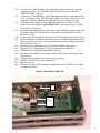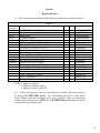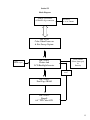
1
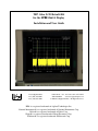
TEP Color LCD Retrofit Kit for the HP 85662A Display Installation and User Guide Test Equipment Plus Tel: (360) 263-5006 Fax: (360) 263-5007 35707 NE 86th Ave., La Center, WA, USA 98629 800-260-TEST www.testequipmentplus.com © 2006 Test Equipment Plus. All Rights Reserved. HP is a registered trademark of Agilent Technologies Inc. National Instruments® is a registered trademark of National Instruments Corp. Parlex is a registered trademark of Parlex Corp. Sharp is a registered trademark of Sharp Electronics Corp. Windows is a registered trademark of Microsoft Corp. ©Copyright 2006 Test Equipment Plus All rights reserved. Publication Number 85662A-M5-1.10 2nd edition, December 2006 Printed in U.S.A. Reproduction, adaptation, or translation without prior written permission is prohibited, except as allowed under the copyright laws. Warranty The information contained in this manual is subject to change without notice. Test Equipment Plus makes no warranty of any kind with regard to this material, including, but not limited to, the implied warranties or merchantability and fitness for a particular purpose. Test Equipment Plus shall not be liable for errors contained herein or for incidental or consequential damages in connection with the furnishing, performance, or use of this material. This Test Equipment Plus product has a warranty against defects in material and workmanship for a period of one year from date of shipment. During the warranty period, Test Equipment Plus will, at its option, either repair or replace products that prove to be defective. Warranty Service For warranty service or repair, this product must be returned to Test Equipment Plus. The Buyer shall pay shipping charges to Test Equipment Plus and Test Equipment Plus shall pay UPS Ground, or equivalent, shipping charges to return the product to the Buyer. However, the Buyer shall pay all shipping charges, duties, and taxes for products returned to Test Equipment Plus from another country. Limitation of Warranty The foregoing warranty shall not apply to defects resulting from improper or inadequate installation by the Buyer, Buyer-supplied software or interfacing, unauthorized modification or misuse, operation outside of the environmental specifications for the product, or improper site preparation or maintenance. No other warranty is expressed or implied. Test Equipment Plus specifically disclaims the implied warranties or merchantability and fitness for a particular purpose. Exclusive Remedies The remedies provided herein are the Buyer’s sole and exclusive remedies. Test Equipment Plus shall not be liable for any direct, indirect, special, incidental, or consequential damages, whether based on contract, tort, or any other legal theory. Certification Test Equipment Plus certifies that, at the time of shipment, this product did not change the published specifications of the instrument it was designed to work in. Test Equipment Plus further certifies that this product does not change the calibration procedure of the instrument it was designed to work in. Warning The Warning symbol calls attention to a procedure, practice, or the like, which if not correctly performed or adhered to, could result in personal injury. Do not proceed beyond a Warning symbol until the indicated conditions are fully understood and met. Test Equipment Plus 35707 NE 86th Ave., La Center, WA 98629 USA 800-260-8378 or 360-263-5006 www.testequipmentplus.com Table of Contents Section Page I General Information . . . . . . . . . . . . . . . . . . . . . . . . 1 1-1 Description . . . . . . . . . . . . . . . . . . . . . . . . . . 1 1-13 Specifications . . . . . . . . . . . . . . . . . . . . . . . . 1 1-15 Calibration . . . . . . . . . . . . . . . . . . . . . . . . . . .1 1-17 Adjustments . . . . . . . . . . . . . . . . . . . . . . . . . .1 1-19 Recommended Tools and Equipment . . . . . . 2 II Installation . . . . . . . . . . . . . . . . . . . . . . . . . . . . . . . . 3 2-1 Initial Inspection . . . . . . . . . . . . . . . . . . . . . . 3 2-2 Installation of the Color LCD Kit . . . . . . . . . 3 III Principles of Operation . . . . . . . . . . . . . . . . . . . . . .10 3-1 A3A4 Color Video Processor . . . . . . . . . . . . 10 3-4 A1A21 Plotter . . . . . . . . . . . . . . . . . . . . . . . . 10 3-5 A1A22 SRAM . . . . . . . . . . . . . . . . . . . . . . . .10 IV Fast Sweep Adjustments . . . . . . . . . . . . . . . . . . . . .11 V Replaceable Parts . . . . . . . . . . . . . . . . . . . . . . . . . . 12 VI Block Diagram . . . . . . . . . . . . . . . . . . . . . . . . . . . . 13 Section I 1-1 1-2 1-3 1-4 1-5 1-6 1-7 1-8 1-9 1-10 1-11 1-12 General Information Description The 8566/8567/8568 Color LCD Retrofit Kit is a drop-in replacement for the monochrome CRT in the HP 85662A display. The Retrofit Kit uses a state-ofthe-art Sharp 6.4” TFT color LCD with a resolution of 640 x 480 pixels. The intensity adjustment works as before; adjust the front panel intensity knob as you would for the CRT. The front panel align adjustment is no longer used. There are two color schemes available. The focus pot adjusted clockwise selects the “Classic” color scheme, and counterclockwise selects the “TEP” color scheme. In the classic color scheme, trace A is shown as yellow, trace B is cyan, and trace C is magenta. Text, graticule, and marker dots are white. Display line and user defined test limit graphics are green. In the TEP color scheme, trace A is shown as green, trace B is shown as red, and trace C is shown as magenta. Text is yellow, and the graticule is blue. Marker dots, display line, and user defined test limit graphics are white. Sweeps of 10mS and faster are now digitized, making it possible to save and print a screen capture in the fast sweep mode. Great care was taken to ensure fast sweep operates virtually identical to how it did when a CRT and analog signal were used. GPIB automation software including verification software is still fully compatible. The kit also includes a software utility to write and print screen captures. The utility can be used with any printer interfaced to a standard Windows 98/2000/ME/XP computer that is equipped with a GPIB card and National Instruments® NI 488.2 drivers. Display-off and -on (shift-G and shift-H) still works as before. The LCD backlight lamp is replaceable and has a typical lifetime of 50,000 hours of operation. The lamp reaches full brightness within 5 minutes of being turn on. To preserve the functionality of the rear panel X, Y, and Z display outputs, the A1A2, A1A4, and A1A5 boards have not been removed. The LCD kit is powered from the unregulated +23V supply that was used for the CRT high voltage. This is a dedicated, fused supply that is isolated from the rest of the power systems. 1-13 1-14 Specifications. Instrument specifications are unchanged. 1-15 1-16 Calibration The calibration procedure is unchanged. 1-17 1-18 Adjustments High Voltage and CRT Display adjustments are obsolete. Fast sweep horizontal offset and gain as well as vertical offset and gain adjustments have been added. They are accessed from the front panel and stored in the new A3A4 nonvolatile memory. 1 1-19 1-20 Recommended Tools & Equipment The LCD kit installation will require the items listed in Table 1-1. Substitutions must meet the critical specifications listed in the table. Item HP® 8566/67/68 Service Manual Signal Generator Function Generator #1 Pozi screwdriver #2 Pozi screwdriver #1 philips screwdriver #10 Torx screwdriver Solder Iron Nibbler File Wire cutters Table 1-1 Critical Specification or Use No Substitutions 1GHz signal @ 0dBm, pulsed 500Hz Square Wave, sync out (TTL) Recommended Model HP 8340B HP 3325B Removal of later s/n covers Modification of A3 card cage Modification of A3 card cage GC Electronics 12-344-4539* *Available upon request from Test Equipment Plus. Also available from Digi-Key, (800)344-4539, or Mouser Electronics (800)346-6873. 2 Section II Installation 2-1 2-2 Initial Inspection. Refer to table 5-1 for a list of parts included in the 85662A-LCD Retrofit Kit. Verify that all parts listed are included in your kit. 2-3 2-4 Installation of the Color LCD Kit. Installation should not be attempted unless it is done so by a highly skilled electronic repair technician. Kit installation time is approximately 3 hours. Refer to spectrum analyzer service manual for location of assemblies. Disconnect AC power cord. Remove all cables connecting the 85662A IF section to the 8566/67/68 RF section. Separate the IF section from the RF section. Remove the top, bottom, and side covers from the 85662A. Remove the eight front corner frame screws connecting the front panel assembly (figure 1) to the four frame struts. Remove the one screw on the bottom center of the front panel assembly that attaches it to the centerline motherboard support. Carefully separate the front panel assembly from the frame struts. 2-5 2-6 2-7 2-8 2-9 2-10 2-11 2-12 2-13 Figure 1: Front Panel Assembly 3 2-14 2-15 2-16 2-17 2-18 2-19 2-20 2-21 2-22 2-23 2-24 2-25 2-26 2-27 2-28 2-29 2-30 2-31 2-32 2-33 2-34 Disconnect the two 14-pin DIP ribbon cable connectors from the motherboard sockets by spreading the retainer clips and pulling the DIP connectors free. Disconnect the 50-pin ribbon cable connector from the top edge of the A1A1 keyboard. Set the front panel assembly aside. NOTE: The following steps refer to the A1A4 and A1A5 video driver boards. On some later model systems, a single board replaces the A1A2, A1A4, and A1A5 boards. This board does not change the circuit layout of the three circuits and the A1A4 and A1A5 circuits can be easily identified as if they were separate boards. Remove the A1A4 board ( 8566/67/68 service manual for circuit board and component locations). Replace A1A4R43 with an 8.25K resistor from the kit and reinstall the A1A4 board. Remove the A1A5 board. Replace A1A5R43 with a 6.49K resistor from the kit and reinstall the A1A5 board. NOTE: Changing resistors on the A1A4 and A1A5 boards preserves the correct X and Y display output amplitude to the rear panel. Warning! Potentially Lethal Voltages Present! Review the 8566/67/68 service manual for; safety guidelines, CRT warnings, and high voltage power supply warnings before proceeding. Carefully discharge the CRT and high voltage power supply. Disconnect and remove the CRT as per the 8566/67/68 service manual. Remove the rear CRT mount entirely rather than just loosening it. Remove three top covers: the A1A3 shielding cage cover, the A1A6/A7/A8 cage cover, and the A1C3 capacitor cover. Lay them aside to be reinstalled later. Remove the A1A3 high voltage power supply and shielding cage. Separate the high voltage power supply from the shielding cage. Set the A1A3 shielding cage aside for later installation. Disconnect the ends of the three SMB cables that are connected to the top of the A3 card cage. Remove the top cover of the A3 card cage. Remove all the A3 cards from the A3 card cage. Remove the A3 card cage. 4 2-35 2-36 2-37 2-38 2-39 Nibble out the third from the top ½” by ⅛” card cage bar on the side of the A3A4 card cage facing the CRT to make a routing path for the A3A4 W2 cable. File smooth any sharp edges caused by the nibbling (figure 2). Replace the A3 card cage and all its cards except for the old A3A4 card. Plug the 12” RJ-45 cable (W2 included in the kit) into the TEP A3A4 board from the kit and install the TEP A3A4 board into the A3A4 card cage slot, working the W2 cable slack out through the nibbled cutout hole. Replace the A3 card cage top cover. Reconnect the three SMB cables that are connected through the top cover of the A3 card cage. Figure 2: Modified A3 Card Cage 5 2-40 2-41 2-42 2-43 2-44 2-45 Solder a 2” wire (W7 included in kit) between A3XA2P2 pin 27 and A3XA4P1 pin 6 on the underside of the A3 motherboard (figure 3). Solder a 2” wire (W8 included in kit) between A3XA2P2 pin 23 and A3XA4P1 pin 24 (figure 3). Route the shorter 6.3” coax cable (W5 included in kit) under the 50-pin ribbon cable and solder the center conductor to A3XA4P1 pin-7 and the shield to A3XA4P1 pin-25. On the other end of the cable, solder the center to A3XA2P1 pin-5 and the shield to A3XA2P1 pin-22 (located diagonally from pin 5) (figure 3). Route the longer 6.8” coax cable (W4 included in kit) under the 50-pin ribbon cable and solder the center conductor to A3XA4P1 pin-8 and the shield to A3XA4P1 pin-26. On the other end of the cable, solder the center to A3XA2P1 pin-4 and the shield to A3XA2P1 pin-21 (located diagonally from pin-4) (figure 3). Figure 3: A3 Wiring Modifications 6 2-46 2-47 2-48 2-49 De-solder and discard the eight L-shaped pins that the CRT plugged into (figure 4) on the motherboard. NOTE: This step is required because the pins no longer have a mating CRT connector that is insulated and so they would be a potential shorting hazard to the instrument cover. Solder the yellow wire on the 23V power cable (W3 included in kit) to connector A1XA6 pin-7 on the bottom of the A1 motherboard (figure 4). Tie strap the yellow wire on cable W3 to the existing motherboard wiring harness (figure 4). On the side of the A1A3 sheet metal shielding cage that faced where the CRT used to be, there will either be a hole in the middle of the side or a notch where the cage meets the motherboard. Figure 4: A1 Modifications 2-50 2-51 2-52 2-53 2-54 2-55 2-56 2-57 If there is a hole in the middle of the side, then feed the 23V power cable edge connector PCB, on cable assembly W3, through the hole and plug it into the empty A1A3 card slot. If there is a notch in the side of the A1A3 cage, then guide the W3 PCB connector through that notch. Reinstall the A1A3 high voltage power supply shielding cage. Ensure the W2 cable passes in front of the A1A3 cage so it will reach the display when installed. Reinstall the A1C3 and A1A6/A7/A8 covers that were removed in step 2-27 and engage cards A1A7 and A1A8 into their guide slots. Reconnect all cable clamps that were disconnected from the A1A3 and A1A6/A7/A8 assemblies. On the old front panel assembly, remove the “Level” and “Intensity” knobs and the retaining nuts underneath them. Lift off the front panel keyboard overlay and set it aside. Remove the eight 4-40 flat-head screws on the front of the keyboard assembly. 7 2-58 2-59 2-60 2-61 2-62 2-63 2-64 2-65 2-66 2-67 2-68 2-69 2-70 2-71 2-72 2-73 2-74 2-75 Remove the keyboard assembly from the old inner bezel casting (figure 5) and transfer it to the modified inner bezel casting provided in the kit. Replace the eight 4-40 flat-head screws on the front of the keyboard assembly. Replace the front panel keyboard overlay, retaining nuts, “Level” knob, and “Intensity” knob. Remove the two small screws from the bottom of the plastic CRT bezel. With the front panel assembly on it’s back so the glass cannot fall out, gently pull the plastic CRT bezel bottom forward until it clears the mounting tabs on the inner bezel casting, then slide it downward to free it’s upper retaining tabs and remove it. Carefully remove the metallized glass window from the old inner bezel casting. Clean the glass with glass cleaner. Install the glass and its plastic CRT bezel and screws into the modified inner bezel casting. Remove the eight 6-32 flat head screws on the front panel assembly attaching the outer bezel casting to the old inner bezel casting. Discard the eight old 6-32 flat head screws. Separate the outer bezel casting from the old inner bezel casting. There should now be nothing attached to the old inner bezel casting (figure 5). NOTE: Save your undamaged old inner bezel casting and return it to Test Equipment Plus for a refund of the core charge. Set the modified inner bezel casting face down and remove the four 6-32 flat head screws on the sides that hold the LCD assembly in place. Lift out the LCD, circuit board sandwich, and mounting brackets, as one LCD assembly. The LCD is only attached to the circuit board sandwich with two cables so take care to keep them together and to not unseat the cables. Remove the protective plastic shipping film from the front of the LCD screen, being careful to not touch the LCD screen. Replace the LCD assembly into the modified inner bezel casting but don’t put the screws in yet. Carefully fit the outer bezel casting onto the modified inner bezel casting and LCD assembly. Replace the four new 6-32 flat head screws that hold the outer bezel casting, inner bezel casting, and LCD assembly together. Install the four remaining new 6-32 flat head screws, provided in the kit, through the outer bezel and into the modified inner bezel casting side mounting tabs. Figure 5: Inner Bezel Casting 8 2-76 2-77 2-78 2-79 2-80 2-81 2-82 2-83 2-84 2-85 2-86 2-87 2-88 2-89 Re-route the 14-pin DIP ribbon cable from the keyboard (that used to go to the motherboard A1J1) to the LCD Kit’s A1A21 Plotter board socket labeled “FRONT PANEL” (figure 6). Connect the 14-pin DIP ribbon cable (W6 included in the kit) to the motherboard A1J1, observing polarity. The W6 ribbon should come off the forward side of the connector, AND pin-1 should go towards the left as viewed from the front. Connect the other end of the 14-pin DIP cable W6 to the LCD Kit’s A1A21 Plotter board socket labeled “MOTHERBOARD”, ensuring cable pin-1 matches to A1A21 pin-1 (figure 6). Re-connect the remaining front panel cables to the 85662A by connecting the 50pin ribbon cable to the keyboard and the remaining 14-pin DIP cable from the keyboard to A3J1. Connect cable W2 from the A3A4 board to its RJ-45 socket on the A1A21 board. Fit the front panel assembly back into the frame and install the eight frame screws that were removed in step 2-11 and the motherboard centerline support screw that was removed in step 2-12. Replace the side and bottom covers and turn the 85662A right side up. Plug cable W3, 4-pin polarized 23V power connector into A1A21J8. Turn the front panel intensity knob fully clockwise. Re-connect the 85662A to the spectrum analyzer RF section, interconnect cables, and AC power. Turn on spectrum analyzer and verify correct operation. Perform section IV Fast Sweep Adjustments. Replace top cover. Place the retrofit kit’s CD instruction manual in front of your HP service manual as supplemental data. Figure 6: Front Panel with LCD J8 Pin-1 9 Section III Principles of Operation 3-1 3-2 3-3 A3A4 Color Video Processor. The A3A4 color video board uses a dual-access memory array. This allows simultaneous use of the video memory by the 85662A data and control bus as well as the color video processor (A3A4U2) that changes the video from monochrome to color and formats the information into a compressed data stream. For sweep times of ≤10 milliseconds (fast sweep), the A3A4 digitizes the fast sweep data that comes in as analog-X and -Y signals. Since the fast sweep data is now captured in digital format it has the added benefit of being able to be saved and printed using the GPIB interface, just like the slower sweeps. 3-4 3-5 A1A21 Plotter. The A1A21 plotter board converts the compressed data into a raster scan format for driving the LCD. 3-6 3-7 A1A22 SRAM. The SRAM board receives raster scan data and stores it in page switched static RAM. Each page contains enough information to paint a full screen on the LCD. There are two pages of static RAM. One page refreshes while the other page paints to the LCD. 10 Section IV Fast Sweep Adjustments 4-1 4-2 4-3 4-4 4-5 4-6 4-7 4-8 4-9 4-10 4-11 4-12 4-13 4-14 4-15 4-16 4-17 4-18 4-19 Allow 30 minutes warm up of spectrum analyzer before adjustments. Enter CENTER FREQUENCY 1 GHz, FREQUENCY SPAN 0 Hz, scale LINEAR, trigger VIDEO, SWEEP TIME 20 msec. Apply a 1GHz signal, 0dBm, and pulsed with a 500Hz square wave to the spectrum analyzer RF input. Enter REFERENCE LEVEL and adjust front panel RPG for full-scale deflection on LCD. Enter SWEEP TIME 10 msec. Enter CF STEP SIZE, [.], [1], [2], [6], [GHz]. The trace color should change to red, indicating you are in adjustment mode. Slowly adjust the horizontal gain, using the front panel RPG, for exactly one vertical line per graticule. Press the AUTO key above the CF STEP SIZE key to save setting. Enter CF STEP SIZE, [.], [1], [2], [7], [GHz]. Slowly adjust the horizontal offset, by rotating the front panel RPG counterclockwise, until the maximum FS ADJ value is reached that will superimpose the vertical signal lines with the vertical graticule lines. NOTE: a vertical line should not be visible on the far left graticule when finished. If there is not enough adjustment range then adjust A3A1R34 to provide the needed range of adjustment. Press the AUTO key above the CF STEP SIZE key to save setting. Steps 4-6 thru 4-11 are interactive. Repeat as needed. Enter CF STEP SIZE, [.], [1], [2], [8], [GHz]. Slowly adjust the vertical offset, using the front panel RPG, until the trace is exactly centered. Press the AUTO key above the CF STEP SIZE key to save setting. Enter CF STEP SIZE, [.], [1], [2], [9], [GHz]. Slowly adjust the vertical gain, using the front panel RPG, until the trace is exactly full scale. Press the AUTO key above the CF STEP SIZE key to save setting. Steps 4-13 thru 4-18 are interactive. Repeat as needed. 11 Section V Replaceable Parts 5-1 This section contains information for ordering replacement parts found in table 5-1. Table 5-1 Ref Designator A1A21 A1A22 A1A23 A3A4 A1A4R43 A1A5R43 Description 85662A LCD Retrofit Kit Plotter board SRAM board Color LCD Display A3A4 Color Video Processor board SS Screw, pan-Philips-SEM, 4-40 x 3/4 SS Screw, 82° flat-pozi, 6-32 x 7/16 SS Screw, 82° flat-pozi, 6-32 x 7/16 Bracket, Left Bracket, Right Manual and Software Utility on CD Modified Inner Bezel Casting Resistor, axial, 1/4W, 8.25K 1% Resistor, axial, 1/4W, 6.49K 1% Cable, ribbon, LCD to SRAM Cable, RJ-45, 12”, Plotter to A3A4 Cable, 23V Power (red/black/yellow wire harness) Cable, Coaxial, 6.8”, Y-axis Cable, Coaxial, 6.3”, X-axis Cable, 14-pin DIP x 6” Wire, 28 AWG, insulated, pre-tinned 2” Qty Note Part Number 1 1 1 1 4 4 4 1 1 1 1 1 1 1 1 1 1 1 1 2 1 1 1 2 1 1 3 1 1 2 1 3 3 1 2 2 2 2 2 3 85662A-LCD-RK 85662A-Plotter 85662A-SRAM 85662A-Display 85662A-A3A4 85662A-M1 85662A-M2 85662A-M2 85662A-M3 85662A-M4 85662A-M5-1.10 85662A-M6 85662A-R1 85662A-R2 85662A-W1 85662A-W2 85662A-W3 85662A-W4 85662A-W5 85662A-W6 85662A-W7 & W8 NOTE: 1. Shipped assembled 2. Shipped in bubble wrap bag. 3. Shipped in plastic 4-dram box 5-2 Before ordering parts, verify the serial number of your kit. This can be accessed by entering CF STEP SIZE, 8,0,8,3. The serial number can also be found on the A1A21, Plotter board that is mounted on the rear of the LCD. Have this information available when ordering. Press AUTO above CF STEP SIZE when finished viewing the serial number from the front panel. 12 Section VI Block Diagram 85662A System Bus A3XA4P1 edge connector Fast Sweep X, Y, FS, LRTRC TEP A3A4 Color Video Processor & Fast Sweep Capture +23V, PWDN signal Color Scheme Select (focus pot) & Intensity TEP A1A21 andAnd Plotter LCD Backlight Inverter Backlight Drive TEP A1A22 Dual Page SRAM TEP A1A23 Sharp® 6.4” TFT Color LCD 13