1
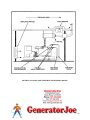
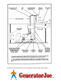
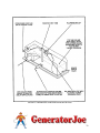
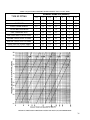
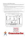
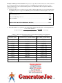
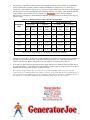
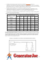
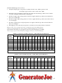
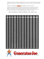
Example Ventilating Air flow Calculation: The generator set Specification Sheet indicates that the heat radiated to
the room from the generator set (engine and generator) is 4,100 BTU/min. The muffler and 10 feet of 5-inch
diameter exhaust pipe are also located inside the generator room. Determine the airflow required to limit the air
temperature rise to 30° F.
1.
Add the heat inputs to the room from all sources. Table 11 indicates that the heat loss from 5-inch exhaust pipe
is 132 BTU per m per foot of pipe and 2,500 BTU per m from the muffler. Add the heat inputs to the room as
follows:
Heat from Generator Set …………………………………………………………………………..4,100
Heat from Exhaust Pipe-10 x 132………………………………………………………………….1,320
Heat from Muffler………………….………………………………………………………………2,500
TOTAL HEAT TO GENERATOR ROOM (BTU/Min.)……………………………………...7,920
2.
The required airflow is proportional to the total heat input divided by the allowable room air temperature rise:
Required Air Flow=
58 x Total Heat (Btu/min.)
Temp. Rise (∆ ºF)
= 58 x 7,920
30
=15,312 cfm
TABLE 11. HEAT LOSSES FROM UNINSULATED EXHAUST PIPES AND MUFFLERS
PIPE DIAMETER
INCHES (mm)
1.5 (38)
HEAT FROM PIPE
BTU/MIN-FOOT (kJ/Min-Metre)
47 (162)
Heat From Muffler
BTU/MIN (kJ/Min-Metre)
297 (313)
2 (51)
57 (197)
490 (525)
2.5 (64)
70 (242)
785 (828)
3 (76)
84 (291)
1,100 (1,160)
3.5 (98)
96 (332)
1,408 (1,485)
4 (102)
108 (374)
1,767 (1,864)
5 (127)
132 (457)
2,500 (2,638)
6 (152)
156 (540)
3,550 (3,745)
8 (203)
200 (692)
5,467 (5,768)
10 (254)
249 (862)
8,500 (8,968)
12 (305)
293 (1,014)
10,083 (10,638)
43