1
Receiving Inspection
inspect the packaging and all parts for damage. Keep all packaging materials for return shipment, if
necessary. If any part is missing or damaged, notify th8 carrier and your nearest Hewlett-Packard
office.
Assembly Procedure
Follow the procedure below to assemble your test set kit on a flat surface before connecting it to the
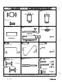
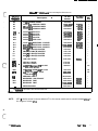
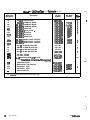
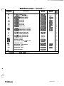
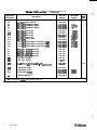
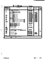
HP 8510 millimeter-wave system. Use the required screws (see identification sheet), and use the *
waveguide stands supplied in the HP 85100A LO/IF Kit (stands support AT2, DC2, DC3 and AT4) or
supplied with racked systems.
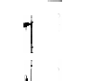
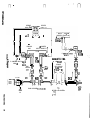
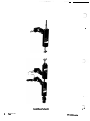
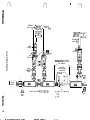
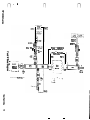
Refer to the Test Set Assembly Diagram and Photograph to properly connect the test set kit.
All of the directional coupler flanges can be easily damaged by improper connections. If you are not
using the HP 11644A waveguide calibration kit straights (with precision flanges) on the test port side of
the couplers, HP 8998 series straights can provide a suitable alternative to avoid damage to the
coupler flanges.
Alignment pins and screws should always be used in a consistent and
R band - Use two alignment pins in opposite corners to align the square shaped flanges. Then
lightly connect them with two screws and nuts. Remove the alignment pins and install th8 other
two screws and nuts. Gradually tighten all four screws in an X pattern.
Q, U, V and W bands - Captive screws are used to make th8 connections.,These partially
threaded screws are designed for repeated use in the tapped round waveguide flanges. Connect
ail four screws lightly. Gradually tighten one screw and then th8 opposite screw to provide even
tOrqU8.
NOTE: Proper connection of waveguide flanges is critical to making good measurements. Be sure
to make the connections as consistent as possible and never ov8rtight8n the connections.
Racked systems (HP 85106A). Refer to the Getting Started section of th8 HP 85106 mm-wave
system manual for instructions about connecting the Test Set kit to the system. The HP 85106A has
portions of the LO/IF section and Test Set kit connections that differ slightly from bench top configurations.
2
Te Set Kits
-J
.
The LO and IF ports of the three harmonic mixers (A7-9) are easily
damaged by electrostatic discharge. Be careful when handling them.
Before Connecting cables to them, short th8 Cab18 outer conductor to
ground. Then short the cable inner conductor to th8 outer conductor.
Finally, short the outer conductor to ground again.
Screws and Alignment Pins.
proper manner as follows:
7
HP ll643A-set-k~
.