1
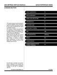
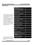
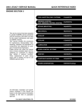
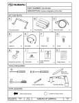
2004 IMPREZA SERVICE MANUAL
QUICK REFERENCE INDEX
ENGINE SECTION 2
This service manual has been prepared
to provide SUBARU service personnel
with the necessary information and data
for the correct maintenance and repair
of SUBARU vehicles.
This manual includes the procedures
for maintenance, disassembling, reassembling, inspection and adjustment of
components and diagnostics for guidance of experienced mechanics.
Please peruse and utilize this manual
fully to ensure complete repair work for
satisfying our customers by keeping
their vehicle in optimum condition.
When replacement of parts during
repair work is needed, be sure to use
SUBARU genuine parts.
FUEL INJECTION (FUEL SYSTEMS)
FU(H4DOTC)
EMISSION CONTROL
(AUX. EMISSION CONTROL DEVICES)
EC(H4DOTC)
INTAKE (INDUCTION)
IN(H4DOTC)
MECHANICAL
ME(H4DOTC)
EXHAUST
EX(H4DOTC)
COOLING
CO(H4DOTC)
LUBRICATION
LU(H4DOTC)
SPEED CONTROL SYSTEMS
SP(H4DOTC)
IGNITION
IG(H4DOTC)
STARTING/CHARGING SYSTEMS
SC(H4DOTC)
ENGINE (DIAGNOSTICS)
EN(H4DOTC)(diag)
All information, illustration and specifications contained in this manual are
based on the latest product information
available at the time of publication
approval.
FUJI HEAVY INDUSTRIES LTD.
G1870GE3
FUEL INJECTION (FUEL SYSTEMS)
FU(H4DOTC)
1.
2.
3.
4.
5.
6.
7.
8.
9.
10.
11.
12.
13.
14.
15.
16.
17.
18.
19.
20.
21.
22.
23.
24.
25.
26.
27.
28.
29.
30.
31.
32.
33.
34.
Page
General Description ....................................................................................2
Throttle Body.............................................................................................13
Intake Manifold..........................................................................................14
Engine Coolant Temperature Sensor........................................................28
Crankshaft Position Sensor.......................................................................29
Camshaft Position Sensor.........................................................................30
AVCS Camshaft Position Sensor..............................................................31
Knock Sensor............................................................................................32
Throttle Position Sensor............................................................................33
Mass Air Flow and Intake Air Temperature Sensor ..................................34
Manifold Absolute Pressure Sensor..........................................................35
Idle Air Control Solenoid Valve .................................................................36
Fuel Injector ..............................................................................................37
Tumble Generator Valve Assembly ..........................................................41
Tumble Generator Valve Actuator.............................................................42
Wastegate Control Solenoid Valve ...........................................................43
Front Oxygen (A/F) Sensor .......................................................................44
Rear Oxygen Sensor.................................................................................46
Exhaust Temperature Sensor ...................................................................48
Engine Control Module (ECM) ..................................................................49
Main Relay ................................................................................................50
Fuel Pump Relay.......................................................................................51
Fuel Pump Control Unit.............................................................................52
Fuel ...........................................................................................................53
Fuel Tank ..................................................................................................54
Fuel Filler Pipe ..........................................................................................57
Fuel Pump.................................................................................................61
Fuel Level Sensor .....................................................................................63
Fuel Sub Level Sensor..............................................................................64
Fuel Filter ..................................................................................................66
Fuel Cut Valve...........................................................................................67
Fuel Damper Valve ...................................................................................68
Fuel Delivery, Return and Evaporation Lines............................................69
Fuel System Trouble in General ...............................................................72
General Description
FUEL INJECTION (FUEL SYSTEMS)
1. General Description
A: SPECIFICATIONS
Fuel tank
Fuel pump
Shutoff discharge pressure
Discharge flow
Fuel filter
60 2 (15.9 US gal, 13.2 Imp gal)
Under rear seat
Impeller
Capacity
Location
Type
450 — 677 kPa (4.59 — 6.9 kg/cm2, 65.27 — 98.2 psi)
More than 130 2 (34.3 US gal, 28.6 Imp gal)/h
[12 V at 300 kPa (3.06 kg/cm2, 43.5 psi)]
Cartridge type
FU(H4DOTC)-2
General Description
FUEL INJECTION (FUEL SYSTEMS)
B: COMPONENT
1. INTAKE MANIFOLD
(20)
T6
T2
(17)
(16)
T6
(15)
T6
T3
T6
T3
(18)
(14)
T3
T6
(19)
T6
(12)
T5
(22)
(13)
(10)
(11)
T7
(21)
T7
T2
T6
(10)
(9)
(25)
(25)
(24)
T2
(8)
(24)
(7)
(9)
(23)
(6)
T6
T4
(14)
(5)
(4)
(2)
(7)
(3)
(1)
T2
(8)
(12)
(13)
(3)
(2)
T2
(3)
(2)
FU-02162
FU(H4DOTC)-3
General Description
FUEL INJECTION (FUEL SYSTEMS)
(1)
(2)
(3)
(4)
(5)
(6)
(7)
(8)
(9)
Fuel pipe ASSY
Fuel hose
Clip
Purge control solenoid valve
Vacuum hose
Vacuum control hose
Intake manifold gasket
Guide pin
Tumble generator valve ASSY
(Except for STi model)
(10)
(11)
Gasket
Accelerator cable bracket
(MT model)
(12)
Fuel injector
(13)
(14)
(15)
(16)
(17)
(18)
(19)
(20)
Insulator
Fuel injector pipe
Pressure regulator
Pressure regulator hose
Fuel pipe protector RH
Blow-by hose stay
Intake manifold
Wastegate control solenoid valve
ASSY
(21)
(22)
(23)
Fuel pipe protector LH
Nipple
Purge valve (Except for Australia
model)
FU(H4DOTC)-4
(24)
Purge hose (Except for Australia
model)
(25)
Tumble generator valve actuator
(Except for STi model)
Tightening torque: N·m (kgf-m, ft-lb)
T1: 5.0 (0.5, 3.6)
T2: 6.4 (0.65, 4.7)
T3: 8.25 (0.84, 6.1)
T4: 16 (1.6, 11.8)
T5: 17 (1.7, 12.5)
T6: 19 (1.9, 14.0)
T7: 25 (2.5, 18.4)
General Description
FUEL INJECTION (FUEL SYSTEMS)
2. AIR INTAKE SYSTEM
T1
(3)
T2
(5)
(7)
(6)
T3
(1)
(2)
(4)
T1
FU-00002
(1)
(2)
(3)
(4)
Gasket
Throttle position sensor
Idle air control solenoid valve
Throttle body
(5)
(6)
(7)
Manifold absolute pressure sensor Tightening torque: N·m (kgf-m, ft-lb)
Gasket
T1: 1.6 (0.16, 1.2)
O-ring
T2: 2.8 (0.29, 2.1)
T3: 22 (2.2, 16.2)
FU(H4DOTC)-5
General Description
FUEL INJECTION (FUEL SYSTEMS)
3. CRANKSHAFT POSITION, CAMSHAFT POSITION AND KNOCK SENSORS
T1
(4)
T2
(3)
T1
T1
T1
(1)
(2)
(4)
FU-00003
(1)
(2)
(3)
Crankshaft position sensor
Knock sensor
Camshaft position sensor
(4)
AVCS camshaft position sensor
(STi model and Australia model)
FU(H4DOTC)-6
Tightening torque: N·m (kgf-m, ft-lb)
T1: 6.4 (0.65, 4.7)
T2: 24 (2.4, 17.4)
General Description
FUEL INJECTION (FUEL SYSTEMS)
4. FUEL TANK
T1
T1
(10)
(30)
(17)
D
(11)
(9)
(7)
E
(15)
(14)
T1
(8)
(29)
(13)
T1
(29)
(12)
C
(10)
(12)
(9)
(28)
(6)
(12)
C
(12)
B
A
(12)
D
(16)
B
F
E
(12)
(12)
(18)
(21) (20)
(5)
(22)
A
(19)
(27)
(12)
(12)
(26)
F
(23)
(12)
(24)
(2)
T3
(20)
T3
(12)
(25)
(21)
(4)
(2)
T2
T2
(1)
(3)
T2
T2
FU-02183
FU(H4DOTC)-7
General Description
FUEL INJECTION (FUEL SYSTEMS)
(1)
(2)
(3)
(4)
(5)
(6)
(7)
(8)
(9)
(10)
(11)
(12)
Heat shield cover
Fuel tank band
Protector LH
Protector RH
Fuel tank
Fuel pump gasket
Fuel pump ASSY
Fuel level sensor
Fuel cut valve gasket
Fuel cut valve
Evaporation hose A
Clip
(13)
(14)
(15)
(16)
(17)
(18)
(19)
(20)
(21)
(22)
(23)
(24)
Evaporation hose B
Joint pipe
Evaporation hose C
Evaporation pipe ASSY
Evaporation pipe
Fuel return hose A
Jet pump hose
Retainer
Quick connector
Evaporation hose D
Fuel pipe ASSY
Fuel return hose B
FU(H4DOTC)-8
(25)
(26)
(27)
(28)
(29)
(30)
Evaporation hose E
Fuel sub level sensor gasket
Jet pump filter
Fuel sub level sensor
Evaporation hose F
Evaporation hose G
Tightening torque: N·m (kgf-m, ft-lb)
T1: 4.4 (0.45, 3.3)
T2: 7.4 (0.75, 5.4)
T3: 33 (3.4, 24.3)
General Description
FUEL INJECTION (FUEL SYSTEMS)
5. FUEL LINE
(19)
B
(24)
(18)
(20)
(17)
A
(16)
(15)
(24)
(25)
(22)
(21) (13)
T
(23)
(14)
B
C
A
(1)
(1)
C
(12)
(8)
(1) (1) (10)
(9)
(1)
(1)
(1)
(1)
(10)
(11)
(7)
(1)
(6)
(2)
(1)
(5)
(4)
(3)
FU-00516
FU(H4DOTC)-9
General Description
FUEL INJECTION (FUEL SYSTEMS)
(1)
(2)
(3)
(4)
(5)
(6)
(7)
(8)
(9)
(10)
Clip
Fuel delivery hose A
Fuel filter bracket
Fuel filter holder
Fuel filter cup
Fuel filter
Evaporation hose
Fuel damper
Fuel delivery hose B
Fuel return hose
(11)
(12)
(13)
(14)
(15)
(16)
(17)
(18)
(19)
(20)
Fuel pipe ASSY
Grommet
Canister hose A
Canister
Canister bracket plate
Cushion
Canister bracket spacer
Rear canister bracket
Two-way valve return hose
Two-way valve
FU(H4DOTC)-10
(21)
(22)
(23)
(24)
(25)
Two-way valve drain hose A
Connector
Two-way valve drain hose B
Clamp
Front canister bracket
Tightening torque: N·m (kgf-m, ft-lb)
T: 23 (2.3, 17.0)
General Description
FUEL INJECTION (FUEL SYSTEMS)
6. FUEL FILLER PIPE
(11)
(9)
(8)
(10)
(12)
T
(1)
(3)
(5)
T
(2)
T
T
(6)
T
(4)
(7)
(3)
FU-00006
(1)
(2)
(3)
(4)
(5)
Fuel filler pipe ASSY
Evaporation hose holder
Clip
Clamp
Air vent hose
(6)
(7)
(8)
(9)
(10)
Air vent pipe
Air vent pipe holder
Filler pipe packing
Filler ring
Filler cap
FU(H4DOTC)-11
(11)
(12)
Filler cap tether
Filler pipe protector
Tightening torque: N·m (kgf-m, ft-lb)
T: 7.5 (0.76, 5.5)
General Description
FUEL INJECTION (FUEL SYSTEMS)
C: CAUTION
• Wear working clothing, including a cap, protective goggles and protective shoes during operation.
• Remove contamination including dirt and corrosion before removal, installation or disassembly.
• Keep the disassembled parts in order and protect them from dust or dirt.
• Before removal, installation or disassembly, be
sure to clarify the failure. Avoid unnecessary removal, installation, disassembly, and replacement.
• Be careful not to burn your hands, because each
part on the vehicle is hot after running.
• Be sure to tighten fasteners including bolts and
nuts to the specified torque.
• Place shop jacks or rigid racks at the specified
points.
• Before disconnecting electrical connectors of
sensors or units, be sure to disconnect the ground
cable from battery.
• Place “NO FIRE” signs near the working area.
• Be careful not to spill fuel on the floor.
D: PREPARATION TOOL
ILLUSTRATION
TOOL NUMBER
24082AA230
DESCRIPTION
CARTRIDGE
REMARKS
Troubleshooting for electrical system.
22771AA030
SUBARU SELECT
MONITOR KIT
Troubleshooting for electrical systems.
• English: 22771AA030 (Without printer)
• German: 22771AA070 (Without printer)
• French: 22771AA080 (Without printer)
• Spanish: 22771AA090 (Without printer)
ST24082AA230
ST22771AA030
FU(H4DOTC)-12
Throttle Body
FUEL INJECTION (FUEL SYSTEMS)
2. Throttle Body
5) Disconnect the engine coolant hoses from throttle body.
A: REMOVAL
1) Disconnect the ground cable from battery.
FU-00012
FU-00009
2) Remove the intercooler. <Ref. to IN(H4DOTC)10, REMOVAL, Intercooler.>
3) Disconnect the connector from the throttle position sensor (A) and idle air control solenoid valve
(B) and manifold absolute pressure sensor (C).
6) Remove the bolts which secure the throttle body
to intake manifold.
B: INSTALLATION
1) Install in the reverse order of removal.
NOTE:
Always use a new gasket.
Tightening torque:
22 N·m (2.2 kgf-m, 16.2 ft-lb)
(B)
(C)
(A)
FU-00010
4) Disconnect the accelerator cable.
FU-00013
2) Adjust the accelerator cable play. <Ref. to
SP(H4SO)-9, INSTALLATION, Accelerator Control
Cable.>
FU-00011
FU(H4DOTC)-13
Intake Manifold
FUEL INJECTION (FUEL SYSTEMS)
3. Intake Manifold
A: REMOVAL
1) Release the fuel pressure. <Ref. to
FU(H4DOTC)-53, RELEASING OF FUEL PRESSURE, OPERATION, Fuel.>
2) Open the fuel filler flap lid and remove the fuel
filler cap.
3) Disconnect the ground cable from battery.
11) Remove the coolant filler tank. <Ref. to
CO(H4DOTC)-33, REMOVAL, Coolant Filler
Tank.>
12) Remove the power steering pump.
(1) Remove the front side V-belt.
<Ref. to ME(H4DOTC)-54, REMOVAL, V-belt.>
(2) Disconnect the power steering switch connector.
FU-00017
FU-00009
4) Lift-up the vehicle.
5) Remove the under cover.
6) Drain the coolant about 3.0 2 (3.2 US qt, 2.6
Imp qt).
(3) Remove the bolts which secure the power
steering pipe brackets to intake manifold.
NOTE:
Do not disconnect the power steering hose.
FU-00018
FU-00016
7) Remove the air cleaner upper cover and air intake boot. <Ref. to IN(H4DOTC)-7, REMOVAL, Air
Cleaner.>
8) Remove the air cleaner element.
9) Remove the intercooler. <Ref. to IN(H4DOTC)10, REMOVAL, Intercooler.>
10) Disconnect the accelerator cable.
(4) Remove the bolts which secure the power
steering pump bracket.
FU-00019
FU-00011
FU(H4DOTC)-14
Intake Manifold
FUEL INJECTION (FUEL SYSTEMS)
(5) Remove the power steering tank from the
bracket by pulling it upward.
15) Disconnect the brake booster hose.
FU-00023
FU-00020
16) Disconnect the pressure hose from intake duct.
(6) Place the power steering pump on right side
wheel apron.
FU-00024
FU-00021
17) Disconnect the engine harness connectors
from bulkhead harness connectors.
13) Disconnect the emission hose from PCV valve.
FU-00025
FU-00022
14) Disconnect the engine coolant hoses from
throttle body.
FU-00026
FU-00012
FU(H4DOTC)-15
Intake Manifold
FUEL INJECTION (FUEL SYSTEMS)
18) Disconnect the connectors from the engine
coolant temperature sensor (A), oil pressure switch
(B) and crankshaft position sensor (C).
22) Disconnect the connector from ignition coil.
(A)
(B)
(C)
FU-00030
FU-00027
23) Disconnect the engine harness fixed by clip (A)
from bracket.
19) Disconnect the knock sensor connector.
(A)
FU-00031
FU-00028
20) Disconnect the connector from crankshaft position sensor.
24) Disconnect the fuel delivery hose, return hose
and evaporation hose.
CAUTION:
• Do not spill fuel.
• Catch the fuel from hoses in a container or
cloth.
FU-00029
21) Disconnect the connector from camshaft position sensor.
FU-00032
25) Remove the bolts which secure the intake manifold to cylinder heads.
FU-00059
FU-00033
FU(H4DOTC)-16
Intake Manifold
FUEL INJECTION (FUEL SYSTEMS)
26) Remove the intake manifold.
4) Connect the connector to knock sensor.
B: INSTALLATION
1) Install the intake manifold onto cylinder heads.
NOTE:
Always use new gaskets.
Tightening torque:
25 N·m (2.5 kgf-m, 18.4 ft-lb)
FU-00028
5) Connect the connector to crankshaft position
sensor.
FU-00033
2) Connect the fuel delivery hose, return hose and
evaporation hose.
FU-00029
6) Connect the connector to camshaft position sensor.
FU-00032
3) Connect the connector to the oil pressure switch
(B), crankshaft position sensor (C) and engine
coolant temperature sensor (A).
FU-00059
(A)
7) Connect the connector to ignition coil.
(B)
(C)
FU-00027
FU-00030
FU(H4DOTC)-17
Intake Manifold
FUEL INJECTION (FUEL SYSTEMS)
8) Connect the engine harness with clip (A) to the
bracket.
11) Connect the engine coolant hoses to throttle
body.
(A)
FU-00012
FU-00031
9) Connect the engine harness connector to bulkhead harness connectors.
12) Connect the emission hose to PCV valve.
FU-00022
FU-00025
13) Connect the pressure hose to intake duct.
FU-00026
10) Connect the brake booster vacuum hose.
FU-00024
14) Install the power steering pump.
(1) Install the power steering tank on bracket.
FU-00023
FU-00020
FU(H4DOTC)-18
Intake Manifold
FUEL INJECTION (FUEL SYSTEMS)
(2) Connect the connector to the power steering
pump switch.
16) Connect the accelerator cable. <Ref. to
SP(H4SO)-9, INSTALLATION, Accelerator Control
Cable.>
FU-00017
(3) Install the power steering pump, and then
tighten the bolts.
Tightening torque:
22 N·m (2.2 kgf-m, 16.2 ft-lb)
FU-00011
17) Install the intercooler. <Ref. to IN(H4DOTC)10, INSTALLATION, Intercooler.>
18) Install the air cleaner element.
19) Install the air cleaner upper cover and air intake
duct as a unit. <Ref. to IN(H4DOTC)-7, INSTALLATION, Air Cleaner.>
20) Connect the connector to the fuel pump relay.
FU-00019
(4) Install the power steering pipe brackets on
right side intake manifold.
FU-00871
21) Connect the battery ground cable to battery.
FU-00018
(5) Install the front side V-belt.
<Ref. to ME(H4DOTC)-54, REMOVAL, V-belt.>
15) Install the coolant filler tank. <Ref. to
CO(H4DOTC)-33, INSTALLATION, Coolant Filler
Tank.>
FU-00009
22) Lift-up the vehicle.
23) Install the under cover.
24) Fill the coolant. <Ref. to CO(H4DOTC)-18,
FILLING OF ENGINE COOLANT, Engine Coolant.>
FU(H4DOTC)-19
Intake Manifold
FUEL INJECTION (FUEL SYSTEMS)
C: DISASSEMBLY
5) Disconnect the engine harness fixed by clip (D)
from intake manifold.
1) Remove the fuel pipe protector LH.
(A)
(C)
(B)
(D)
FU-00968
(D)
FU-00038
6) Remove the throttle body from intake manifold.
2) Remove the fuel pipe protector RH.
FU-00013
FU-00969
3) Remove the engine ground cable from intake
manifold.
7) Disconnect the connector from fuel injector.
FU-00615
FU-00036
8) Disconnect the connector from tumble generator
valve actuator. (Except for STi model)
FU-00037
FU-00616
4) Disconnect the connector from the throttle position sensor (A), idle air control solenoid valve (B)
and manifold absolute pressure sensor (C).
FU(H4DOTC)-20
Intake Manifold
FUEL INJECTION (FUEL SYSTEMS)
9) Disconnect the connector from tumble generator
valve sensor. (Except for STi model)
13) Disconnect the evaporation hose from purge
valve. (Except for Australia model)
FU-00617
10) Disconnect the connector from purge control
solenoid valve.
FU-00364
14) Remove the two bolts which hold the fuel pipes
on the left side of intake manifold.
FU-00040
11) Remove the purge control solenoid valve.
FU-00043
15) Remove the bolts which hold the fuel injector
pipe onto intake manifold.
• LH SIDE
FU-00041
12) Disconnect the evaporation hose from intake
manifold.
FU-00042
FU(H4DOTC)-21
FU-00044
FU-00618
Intake Manifold
FUEL INJECTION (FUEL SYSTEMS)
• RH SIDE
19) Loosen the clamp which holds the front left side
fuel hose to injector pipe, and remove the pipe from
clamp.
FU-00046
FU-00620
20) Remove the fuel injector pipe LH.
21) Remove the bolts which install the fuel pipe on
intake manifold.
FU-00619
16) Remove the fuel injector.
FU-00051
22) Remove the fuel pipe assembly and pressure
regulator from intake manifold.
23) Remove the intake duct from intake manifold.
FU-00048
17) Remove the harness bracket which holds the
engine harness onto intake manifold.
FU-00052
24) Remove the intake manifold.
FU-00049
18) Remove the engine harness from intake manifold.
FU-00053
FU(H4DOTC)-22
Intake Manifold
FUEL INJECTION (FUEL SYSTEMS)
D: ASSEMBLY
5) Connect the left side fuel hose to injector pipe,
and tighten the clamp screw.
NOTE:
Replace the gasket with a new one.
1) Install the intake manifold.
Tightening torque:
8.25 N·m (0.84 kgf-m, 6.1 ft-lb)
FU-00620
6) Install the engine harness to intake manifold.
7) Install the harness bracket which holds the engine harness onto intake manifold.
FU-00053
Tightening torque:
19 N·m (1.9 kgf-m, 14.0 ft-lb)
2) Install the air intake duct to intake manifold.
Tightening torque:
19 N·m (1.9 kgf-m, 14.0 ft-lb)
FU-00049
8) Install the fuel injector.
FU-00052
3) Install the fuel pipe assembly and pressure regulator to intake manifold.
Tightening torque:
4.9 N·m (0.5 kgf-m, 3.6 ft-lb)
FU-00048
FU-00051
4) Install the fuel injector pipe LH.
FU(H4DOTC)-23
Intake Manifold
FUEL INJECTION (FUEL SYSTEMS)
9) Tighten the bolts which install the fuel injector
pipe onto intake manifold.
10) Tighten the two bolts which install the fuel pipes
on the left side of intake manifold.
Tightening torque:
19 N·m (1.9 kgf-m, 14.0 ft-lb)
• LH SIDE
Tightening torque:
4.9 N·m (0.5 kgf-m, 3.6 ft-lb)
FU-00043
FU-00044
11) Connect the evaporation hoses to the purge
valve. (Except for Australia model)
NOTE:
Connect the evaporation hose as shown in the figure.
(B)
FU-00618
(A)
• RH SIDE
(C)
(D)
FU-00046
FU-00365
(A)
(B)
(C)
(D)
FU-00619
FU(H4DOTC)-24
To fuel pipe ASSY
To intake duct
To purge control solenoid valve
To intake manifold
Intake Manifold
FUEL INJECTION (FUEL SYSTEMS)
12) Connect the evaporation hose to intake manifold.
15) Connect the connector to the purge control solenoid valve.
FU-00042
13) Install the purge control solenoid valve.
Tightening torque:
16 N·m (1.6 kgf-m, 11.8 ft-lb)
FU-00040
16) Connect the connector to the tumble generator
valve sensor. (Except for STi model)
FU-00617
FU-00041
14) Connect the hoses to the purge control solenoid valve.
17) Connect the connector to the tumble generator
valve actuator. (Except for STi model)
NOTE:
Connect the evaporation hose as shown in the figure.
FU-00616
18) Connect the connector to fuel injector.
(A)
(B)
FU-00054
(A) To intake manifold
(B) To fuel pipe (Australia model)
To purge valve (Except for Australia model)
FU-00615
FU(H4DOTC)-25
Intake Manifold
FUEL INJECTION (FUEL SYSTEMS)
19) Install the throttle body to intake manifold.
NOTE:
Replace the gasket with a new one.
22) Install the engine ground cable to intake manifold.
Tightening torque:
19 N·m (1.9 kgf-m, 14.0 ft-lb)
Tightening torque:
22 N·m (2.2 kgf-m, 16.2 ft-lb)
FU-00036
FU-00013
20) Connect the connector to the throttle position
sensor (A), idle air control solenoid valve (B) and
manifold absolute pressure sensor (C).
21) Connect the engine harness with clip (D) to intake manifold.
(A)
(C)
(B)
FU-00037
23) Install the fuel pipe protector RH.
Tightening torque:
19 N·m (1.9 kgf-m, 14.0 ft-lb)
(D)
(D)
FU-00038
FU-00969
FU(H4DOTC)-26
Intake Manifold
FUEL INJECTION (FUEL SYSTEMS)
24) Install the fuel pipe protector LH.
Tightening torque:
19 N·m (1.9 kgf-m, 14.0 ft-lb)
FU-00968
E: INSPECTION
Make sure the fuel pipe and fuel hoses are not
cracked and the connections are tightened firmly.
FU(H4DOTC)-27
Engine Coolant Temperature Sensor
FUEL INJECTION (FUEL SYSTEMS)
4. Engine Coolant Temperature
Sensor
A: REMOVAL
1) Disconnect the ground cable from battery.
FU-00009
2) Remove the generator. <Ref. to SC(H4SO)-13,
REMOVAL, Generator.>
3) Drain
the
engine
coolant.
<Ref.
to
CO(H4DOTC)-18, DRAINING OF ENGINE COOLANT, REPLACEMENT, Engine Coolant.>
4) Disconnect the connector from engine coolant
temperature sensor.
FU-00055
5) Remove the engine coolant temperature sensor.
B: INSTALLATION
Install in the reverse order of removal.
Tightening torque:
18 N·m (1.8 kgf-m, 13.3 ft-lb)
FU(H4DOTC)-28
Crankshaft Position Sensor
FUEL INJECTION (FUEL SYSTEMS)
5. Crankshaft Position Sensor
B: INSTALLATION
A: REMOVAL
Install in the reverse order of removal.
1) Disconnect the ground cable from battery.
Tightening torque:
T: 6.4 N·m (0.65 kgf-m, 4.7 ft-lb)
T
FU-00009
2) Remove the bolt which installs the crankshaft
position sensor to cylinder block.
FU-00056
3) Remove the crankshaft position sensor, and disconnect the connector from it.
FU-00057
FU(H4DOTC)-29
FU-00058
Camshaft Position Sensor
FUEL INJECTION (FUEL SYSTEMS)
6. Camshaft Position Sensor
B: INSTALLATION
A: REMOVAL
Install in the reverse order of removal.
1) Disconnect the ground cable from battery.
Tightening torque:
T: 6.4 N·m (0.65 kgf-m, 4.7 ft-lb)
FU-00009
2) Disconnect the connector from camshaft position sensor.
FU-00059
3) Remove the camshaft position sensor from camshaft support LH.
FU-00060
FU(H4DOTC)-30
FU-00060
AVCS Camshaft Position Sensor
FUEL INJECTION (FUEL SYSTEMS)
7. AVCS Camshaft Position
Sensor
A: REMOVAL
NOTE:
This component is installed to STi and Australia
model.
1) Disconnect the ground cable from battery.
2) Remove the intercooler. <Ref. to IN(H4DOTC)10, REMOVAL, Intercooler.>
3) Remove the intake manifold. <Ref. to
FU(H4DOTC)-14, REMOVAL, Intake Manifold.>
4) Disconnect the AVCS camshaft position sensor
connector.
5) Remove the AVCS camshaft position sensor.
FU-00061
B: INSTALLATION
Install in the reverse order of removal.
FU(H4DOTC)-31
Knock Sensor
FUEL INJECTION (FUEL SYSTEMS)
8. Knock Sensor
B: INSTALLATION
A: REMOVAL
1) Install the knock sensor to cylinder block.
1) Disconnect the ground cable from battery.
Tightening torque:
24 N·m (2.4 kgf-m, 17.4 ft-lb)
NOTE:
Extraction area of knock sensor cord must be positioned at a 60° angle relative to engine rear.
(A)
FU-00009
2) Remove the intercooler. <Ref. to IN(H4DOTC)10, REMOVAL, Intercooler.>
3) Disconnect the knock sensor connector.
60
FU-00413
(A) Front side
2) Connect the knock sensor connector.
FU-00062
4) Remove the knock sensor from cylinder block.
FU-00062
3) Install the intercooler. <Ref. to IN(H4DOTC)-10,
INSTALLATION, Intercooler.>
4) Connect the battery ground cable to battery.
FU-00519
FU-00009
FU(H4DOTC)-32
Throttle Position Sensor
FUEL INJECTION (FUEL SYSTEMS)
9. Throttle Position Sensor
B: INSTALLATION
A: REMOVAL
Install in the reverse order of removal.
1) Disconnect the ground cable from battery.
Tightening torque:
1.6 N·m (0.16 kgf-m, 1.2 ft-lb)
FU-00009
2) Remove the intercooler. <Ref. to IN(H4DOTC)10, REMOVAL, Intercooler.>
3) Disconnect the connector from throttle position
sensor.
FU-00065
4) Remove the throttle position sensor holding
screws, and remove it.
FU-00066
FU(H4DOTC)-33
FU-00066
Mass Air Flow and Intake Air Temperature Sensor
FUEL INJECTION (FUEL SYSTEMS)
10.Mass Air Flow and Intake Air
Temperature Sensor
A: REMOVAL
1) Disconnect the ground cable from battery.
FU-00009
2) Disconnect the connector from mass air flow and
intake air temperature sensor.
3) Remove the mass air flow and intake air temperature sensor.
FU-00067
B: INSTALLATION
Install in the reverse order of removal.
Tightening torque:
1.7 N·m (0.17 kgf-m, 1.2 ft-lb)
FU(H4DOTC)-34
Manifold Absolute Pressure Sensor
FUEL INJECTION (FUEL SYSTEMS)
11.Manifold Absolute Pressure
Sensor
A: REMOVAL
1) Disconnect the ground cable from battery.
FU-00009
2) Remove the idle air control solenoid valve. <Ref.
to FU(H4DOTC)-36, REMOVAL, Idle Air Control
Solenoid Valve.>
3) Disconnect the connectors from manifold absolute pressure sensor.
FU-00068
4) Remove the manifold absolute pressure sensor
from throttle body.
B: INSTALLATION
Install in the reverse order of removal.
NOTE:
Replace the O-rings for manifold absolute pressure
sensor with new ones.
Tightening torque:
1.6 N·m (0.16 kgf-m, 1.2 ft-lb)
FU(H4DOTC)-35
Idle Air Control Solenoid Valve
FUEL INJECTION (FUEL SYSTEMS)
12.Idle Air Control Solenoid
Valve
A: REMOVAL
1) Disconnect the ground cable from battery.
B: INSTALLATION
Install in the reverse order of removal.
NOTE:
Replace the gasket with a new one.
Tightening torque:
2.8 N·m (0.29 kgf-m, 2.1 ft-lb)
FU-00009
2) Disconnect the connector from idle air control
solenoid valve.
FU-00070
3) Remove the idle air control solenoid valve from
throttle body.
FU-00071
4) Remove the gasket from throttle body.
FU-00072
FU(H4DOTC)-36
FU-00071
Fuel Injector
FUEL INJECTION (FUEL SYSTEMS)
13.Fuel Injector
7) Remove the bolts which hold the injector pipe to
intake manifold.
A: REMOVAL
1. RH SIDE
1) Release the fuel pressure. <Ref. to
FU(H4DOTC)-53, RELEASING OF FUEL PRESSURE, OPERATION, Fuel.>
2) Open the fuel filler flap lid and remove the fuel
filler cap.
3) Disconnect the ground cable from battery.
FU-00046
FU-00009
4) Remove the intake manifold. <Ref. to
FU(H4DOTC)-14, REMOVAL, Intake Manifold.>
5) Remove the fuel pipe protector RH.
FU-00619
8) Remove the fuel injector while lifting up the fuel
injector pipe.
FU-00035
FU-00048
6) Disconnect the connector from fuel injector.
2. LH SIDE
1) Release the fuel pressure. <Ref. to
FU(H4DOTC)-53, RELEASING OF FUEL PRESSURE, OPERATION, Fuel.>
2) Open the fuel filler flap lid and remove the fuel
filler cap.
3) Disconnect the ground cable from battery.
FU-00615
FU-00009
FU(H4DOTC)-37
Fuel Injector
FUEL INJECTION (FUEL SYSTEMS)
4) Remove the intake manifold. <Ref. to
FU(H4DOTC)-14, REMOVAL, Intake Manifold.>
5) Remove the fuel pipe protector LH.
7) Remove the bolts which hold the injector pipe to
intake manifold.
FU-00043
FU-00968
6) Disconnect the connector from fuel injector.
FU-00618
FU-00615
FU-00044
8) Remove the fuel injector while lifting up the fuel
injector pipe.
FU-00048
FU(H4DOTC)-38
Fuel Injector
FUEL INJECTION (FUEL SYSTEMS)
B: INSTALLATION
Tightening torque:
19 N·m (1.9 kgf-m, 14.0 ft-lb)
1. RH SIDE
Install in the reverse order of removal.
NOTE:
Replace the O-ring and insulators with new ones.
(A)
(C)
FU-00035
(B)
2. LH SIDE
(C)
Install in the reverse order of removal.
FU-00073
NOTE:
Replace the O-ring and insulators with new ones.
(A) O-ring
(B) Fuel injector
(C) Insulator
Tightening torque:
19 N·m (1.9 kgf-m, 14.0 ft-lb)
(A)
(C)
(B)
(C)
FU-00073
(A) O-ring
(B) Fuel injector
(C) Insulator
FU-00046
Tightening torque:
19 N·m (1.9 kgf-m, 14.0 ft-lb)
Tightening torque:
6.4 N·m (0.65 kgf-m, 4.7 ft-lb)
FU-00043
FU-00619
FU(H4DOTC)-39
Fuel Injector
FUEL INJECTION (FUEL SYSTEMS)
Tightening torque:
19 N·m (1.9 kgf-m, 14.0 ft-lb)
FU-00044
Tightening torque:
19 N·m (1.9 kgf-m, 14.0 ft-lb)
FU-00618
Tightening torque:
19 N·m (1.9 kgf-m, 14.0 ft-lb)
FU-00968
FU(H4DOTC)-40