1
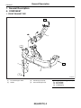
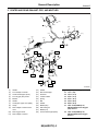
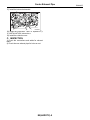
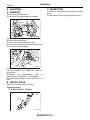
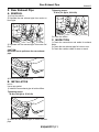
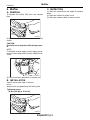
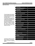
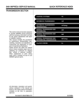
2004 LEGACY SERVICE MANUAL
QUICK REFERENCE INDEX
ENGINE SECTION 2
This service manual has been prepared
to provide SUBARU service personnel
with the necessary information and data
for the correct maintenance and repair
of SUBARU vehicles.
This manual includes the procedures
for maintenance, disassembling, reassembling, inspection and adjustment of
components and diagnostics for guidance of experienced mechanics.
Please peruse and utilize this manual
fully to ensure complete repair work for
satisfying our customers by keeping
their vehicle in optimum condition.
When replacement of parts during
repair work is needed, be sure to use
SUBARU genuine parts.
FUEL INJECTION (FUEL SYSTEMS)
FU(H4DOTC)
EMISSION CONTROL
(AUX. EMISSION CONTROL DEVICES)
EC(H4DOTC)
INTAKE (INDUCTION)
IN(H4DOTC)
MECHANICAL
ME(H4DOTC)
EXHAUST
EX(H4DOTC)
COOLING
CO(H4DOTC)
LUBRICATION
LU(H4DOTC)
SPEED CONTROL SYSTEMS
SP(H4DOTC)
IGNITION
IG(H4DOTC)
STARTING/CHARGING SYSTEMS
SC(H4DOTC)
ENGINE (DIAGNOSTICS)
EN(H4DOTC)(diag)
All information, illustration and specifications contained in this manual are
based on the latest product information
available at the time of publication
approval.
FUJI HEAVY INDUSTRIES LTD.
G2320GE3
EXHAUST
EX(H4DOTC)
1.
2.
3.
4.
5.
6.
Page
General Description ....................................................................................2
Front Exhaust Pipe......................................................................................5
Center Exhaust Pipe ...................................................................................6
Joint Pipe ..................................................................................................10
Rear Exhaust Pipe ....................................................................................11
Muffler .......................................................................................................12
General Description
EXHAUST
1. General Description
A: COMPONENT
1. FRONT EXHAUST PIPE
T1
(2)
(3)
T1
T2
(4)
(1)
T3
EX-00248
(1)
(2)
Front exhaust pipe ASSY
Gasket
(3)
(4)
Turbocharger joint pipe
Front exhaust pipe cover
EX(H4DOTC)-2
Tightening torque: N⋅m (kgf-m, ft-lb)
T1: 35 (3.6, 26.0)
T2: 30 (3.1, 22.1)
T3: 7.5 (0.76, 5.5)
General Description
EXHAUST
2. CENTER AND REAR EXHAUST PIPE, AND MUFFLER
(15)
(15)
(19)
(18)
(15)
(21)
(18)
(15)
(15)
(17)
(13)
(16)
T6
(20)
(12)
(14)
(10)
T5
(1)
A
T7
(4)
T8
(7)
A
(22)
(3)
(2)
T2
(11)
T4
(6)
(8)
T5
T1
(9)
T5
T1
(5)
(1)
(2)
(3)
(4)
(5)
(6)
(7)
(8)
(9)
Gasket
Front catalytic converter
Center exhaust pipe (Front)
Front oxygen (A/F) sensor
Bracket
Gasket
Center pipe upper cover (Rear)
Clamp
Rear catalytic converter lower
cover
(10)
(11)
Rear oxygen sensor
Rear catalytic converter
(12)
(13)
(14)
(15)
(16)
(17)
(18)
(19)
(20)
(21)
(22)
T3
Gasket
Rear exhaust pipe
Chamber
Cushion rubber
Spring
Bolt
Gasket
Muffler (RH)
Self-locking nut
Muffler (LH)
Center exhaust pipe (Rear)
EX(H4DOTC)-3
EX-02005
Tightening torque: N⋅m (kgf-m, ft-lb)
T1: 13 (1.3, 9.6)
T2: 18 (1.8, 13.3)
T3: 23 (2.3, 17.0)
T4: 30 (3.1, 22.1)
T5: 35 (3.6, 26.0)
T6: 48 (4.9, 35.4)
T7: <Ref. to FU(H4DOTC)-33,
INSTALLATION, Front Oxygen
(A/F) Sensor.>
T8: <Ref. to FU(H4DOTC)-34,
INSTALLATION, Rear Oxygen
Sensor.>
General Description
EXHAUST
B: CAUTION
• Wear work clothing, including a cap, protective
goggles and protective shoes during operation.
• Remove contamination including dirt and corrosion before removal, installation or disassembly.
• Keep the disassembled parts in order and protect them from dust and dirt.
• Before removal, installation or disassembly, be
sure to clarify the failure. Avoid unnecessary removal, installation, disassembly and replacement.
• Be careful not to burn yourself, because each
part on the vehicle is hot after running.
• Be sure to tighten fasteners including bolts and
nuts to the specified torque.
• Place shop jacks or rigid racks at the specified
points.
• Before disconnecting electrical connectors of
sensors or units, be sure to disconnect the ground
cable from battery.
EX(H4DOTC)-4
Front Exhaust Pipe
EXHAUST
2. Front Exhaust Pipe
2) Install the front exhaust pipe assembly to turbocharger joint pipe.
A: REMOVAL
1) Lift-up the vehicle.
2) Remove the under cover.
3) Remove the front exhaust pipe cover.
4) Remove the nuts which hold front exhaust pipe
assembly onto turbocharger joint pipe.
Tightening torque:
35 N⋅m (3.6 kgf-m, 26.0 ft-lb)
EX-00201
EX-00201
5) While holding the front exhaust pipe assembly,
remove the nuts which hold front exhaust pipe assembly to cylinder head exhaust port.
3) Install the front exhaust pipe cover.
4) Install the under cover.
5) Lower the vehicle.
C: INSPECTION
1) Check the connections and welds for exhaust
leaks.
2) Check the rear exhaust pipe for holes or rust.
EX-00202
6) Remove the front exhaust pipe assembly.
B: INSTALLATION
NOTE:
Use a new gasket.
1) Install the front exhaust pipe assembly.
Tightening torque:
30 N⋅m (3.1 kgf-m, 22.1 ft-lb)
EX-00202
EX(H4DOTC)-5
Center Exhaust Pipe
EXHAUST
3. Center Exhaust Pipe
12) Remove the turbocharger cover.
A: REMOVAL
1) Set the vehicle on a lift.
2) Remove the collector cover.
3) Disconnect the ground cable from battery.
4) Remove the intercooler. <Ref. to IN(H4DOTC)12, REMOVAL, Intercooler.>
5) Remove the intercooler bracket.
(B)
(A)
EX-00249
(A) Linear motion mounting bracket
(B) Turbocharger cover
13) Separate the center exhaust pipe from turbocharger.
EX-00203
6) Lift-up the vehicle.
7) Remove the under cover.
8) Remove the universal joint bolts and then remove the universal joint.
CAUTION:
Scribe alignment marks on the universal joint
so that it can be reassembled at the original
serration.
EX-00204
14) Disconnect the connector from front oxygen (A/
F) sensor.
EX-00008
9) Lower the vehicle.
10) Remove the linear motion mounting. <Ref. to
ME(H4DOTC)-37, REMOVAL, Linear Motion
Mounting.>
11) Remove the linear motion mounting bracket.
EX-00205
15) Lift-up the vehicle.
16) Disconnect the connector from rear oxygen
sensor.
EX-00206
EX(H4DOTC)-6
Center Exhaust Pipe
EXHAUST
17) Separate the center exhaust pipe from rear exhaust pipe.
3) Connect the center exhaust pipe to turbocharger.
Tightening torque:
35 N⋅m (3.6 kgf-m, 26.0 ft-lb)
EX-00207
18) Remove the bolt which holds center exhaust
pipe bracket to transmission.
EX-00204
4) Install the center exhaust pipe to rear exhaust
pipe.
Tightening torque:
35 N⋅m (3.6 kgf-m, 26.0 ft-lb)
EX-00208
19) Remove the intercooler bracket.
20) Remove the bolt which holds center exhaust
pipe to hanger bracket.
CAUTION:
Be careful not to pull down the center exhaust
pipe.
EX-00207
5) Connect the connector to rear oxygen sensor.
EX-00209
21) Remove the center exhaust pipe.
B: INSTALLATION
NOTE:
Use a new gasket.
1) Install the center exhaust pipe and temporarily
tighten the bolt which holds center exhaust pipe to
hanger bracket.
2) Temporarily tighten the bolt which holds center
exhaust pipe to transmission.
EX(H4DOTC)-7
EX-00206
Center Exhaust Pipe
EXHAUST
6) Tighten the bolt which holds center exhaust pipe
bracket to transmission.
12) Connect the connector of front oxygen (A/F)
sensor.
Tightening torque:
30 N⋅m (3.1 kgf-m, 22.1 ft-lb)
EX-00205
EX-00208
7) Tighten the bolt which holds center exhaust pipe
to hanger bracket.
Tightening torque:
35 N⋅m (3.6 kgf-m, 26.0 ft-lb)
EX-00209
8) Lower the vehicle.
9) Install the turbocharger cover.
10) Install the linear motion mounting bracket.
Tightening torque:
T1: 7.4 N⋅m (0.75 kgf-m, 5.4 ft-lb)
T2: 40 N⋅m (4.1 kgf-m, 29.5 ft-lb)
T1
Tightening torque:
24 N⋅m (2.4 kgf-m, 17.4 ft-lb)
CAUTION:
• Make sure the universal joint bolts are tightened through the shaft serration notches.
• Excessively large tightening torque of universal joint bolts may lead to heavy steering
wheel operation.
Standard clearance between gearbox and DOJ:
15 mm (0.59 in) or more
T1
(A)
13) Lift-up the vehicle.
14) Install the universal joint.
(1) Align the bolt hole on the long yoke side of
universal joint with the cutout at the serrated
section of shaft end, and then insert the universal joint.
(2) Align the bolt hole on the short yoke side of
universal joint with the cutout at the serrated
section of gearbox assembly. Lower the universal joint completely.
(3) Temporarily tighten the bolt of short yoke
side. Raise the universal joint to make sure the
bolt is properly passing through the cutout at the
serrated section.
(4) Tighten the long yoke side bolt, and also
tighten the short yoke side bolt.
(B)
T1
T1
T2
EX-00250
(A) Linear motion mounting bracket
(B) Turbocharger cover
EX-00008
11) Install the linear motion mounting. <Ref. to
ME(H4DOTC)-37, INSTALLATION, Linear Motion
Mounting.>
15) Install the under cover.
16) Lower the vehicle.
EX(H4DOTC)-8
Center Exhaust Pipe
EXHAUST
17) Install the intercooler bracket.
EX-00203
18) Install the intercooler. <Ref. to IN(H4DOTC)12, INSTALLATION, Intercooler.>
19) Install the collector cover.
C: INSPECTION
1) Check the connections and welds for exhaust
leaks.
2) Check the rear exhaust pipe for holes or rust.
EX(H4DOTC)-9
Joint Pipe
EXHAUST
4. Joint Pipe
C: INSPECTION
A: REMOVAL
1) Check the connections and welds for exhaust
leaks.
2) Check the rear exhaust pipe for holes or rust.
1) Remove the collector cover.
2) Disconnect the ground cable from battery.
IN-00203
3) Lift-up the vehicle.
4) Remove the under cover.
5) Remove the front exhaust pipe cover.
6) Remove the nuts which hold front exhaust manifold to turbocharger joint pipe.
EX-00201
7) Remove the center exhaust pipe.
<Ref. to EX(H4DOTC)-6, REMOVAL, Center Exhaust Pipe.>
8) Remove
the
turbocharger.
<Ref.
to
IN(H4DOTC)-14, REMOVAL, Turbocharger.>
9) Remove the joint pipe from the lower side of vehicle.
B: INSTALLATION
Install in the reverse order of removal.
Tightening torque:
T: 35 N⋅m (3.6 kgf-m, 26.0 ft-lb)
T
T
EX-02019
EX(H4DOTC)-10
Rear Exhaust Pipe
EXHAUST
5. Rear Exhaust Pipe
Tightening torque:
35 N⋅m (3.6 kgf-m, 26.0 ft-lb)
A: REMOVAL
1) Lift-up the vehicle.
2) Separate the rear exhaust pipe from center exhaust pipe.
EX-00207
3) Lower the vehicle.
C: INSPECTION
EX-00207
3) Separate the rear exhaust pipe from both mufflers.
CAUTION:
Be careful not to pull down the rear exhaust
pipe.
1) Check the connections and welds for exhaust
leaks.
2) Check the rear exhaust pipe for holes or rust.
3) Check the cushion rubber for wear or crack.
EX-00210
4) Remove the rear exhaust pipe.
B: INSTALLATION
NOTE:
Use a new gasket.
1) Install the rear exhaust pipe to both mufflers.
Tightening torque:
48 N⋅m (4.9 kgf-m, 35.4 ft-lb)
EX-00210
2) Install the rear exhaust pipe to center exhaust
pipe.
EX(H4DOTC)-11
Muffler
EXHAUST
6. Muffler
C: INSPECTION
A: REMOVAL
1) Check the connections and welds for exhaust
leaks.
2) Check the mufflers for holes or rust.
3) Check the cushion rubber for wear or crack.
1) Separate the muffler (RH) from rear exhaust
pipe.
EX-00210
2) Remove the cushion rubbers, and detach the
muffler.
CAUTION:
Be careful not to drop the muffler during removal.
NOTE:
To facilitate removal, apply a coat of spray type lubricant to the mating area of cushion rubbers in advance.
EX-00211
3) Perform the same procedure for muffler (LH).
B: INSTALLATION
Install in the reverse order of removal.
NOTE:
Always use a new gasket and self-locking nuts.
Tightening torque:
48 N⋅m (4.9 kgf-m, 35.4 ft-lb)
EX-00210
EX(H4DOTC)-12