1
PROPELLER SHAFT &
DIFFERENTIAL CARRIER
SECTION
PD
CONTENTS
PROPELLER SHAFT
FINAL DRIVE (Model R200)
PD- 2
,
.
..
ON-VEHICLE SERVICE (Model R200)
REMOVAL AND INSTALLATION (Model R200)
DISASSEMBLY (Model R200)
INSPECTION (Model R200)
ADJUSTMENT (Model R200)
. .
ASSEMBLY (Model R200)
SERVICE DATA AND SPECIFICATIONS
SPECIAL SERVICE TOOLS
(SD S
PD- 4
PD- 5
PD- 7
...
PD- 8
PD-13
PD-14
PD-24
PD-30
PD-32
PROPELLER SHAFT
~
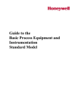
Companion flange
PO427
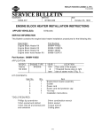
General I spection
0
Inspect propeller shaft tube surface for dents
or cracks.
I f damaged, replace propeller shaft assembly
I f center bearing is noisy or damaged, replace
center bearing.
\
PROPELLER SHAFT VIBRATION
To check and correct an unbalanced propeller
shaft, proceed as follows
1 Remove undercoating and other foreign
material which could upset shaft balance, and
check shaft vibration by road test.
2. If shaft vibration is noted during road test,
disconnect propeller shaft a t differential
carrier companion flange, rotate companion
flange 180 degrees and reconnect propeller
shaft
/
3
PD-2
SPDlO2
Again check shaft vibration If vibration
still persists, replace propeller shaft assembly.
PROPELLER SHAFT
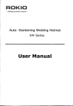
Inspection
Removal and Installation
Put match marks on flanges and separate
propeller shaft from differential carrier
Inspect propeller shaft runout. I f runout
exceeds specifications, replace propeller shaft
assembly
R
SPDlOS
SPD103
Draw out propeller shaft from transmission
and plug up rear end of transmission rear
extension housing
Runout limit: 0 6 mm (0.024 in)
Inspect journal axial play.
I f the play exceeds specifications, replace
propeller shaft assembly.
Journal axial play:
0 mm ( 0 in)
Transmission
7
SPD359
PD-3
FINAL DRIVE (Model R200)
SPD516
PD-4
ON-VEHICLE SERVICE (Model R200)
Front Oil Seal Replacement
1. Remove propeller shaft
2. Loosen drive pinion nut.
rToal
Tool number. ST31520000 (
5 Apply multi-purpose grease t o cavity at sealing
lips of oil seal.
\
-
Press front oil seal into carrier.
)
Tool number: KV38100500 (
3. Remove companion flange.
-
)
6. Install companion flange and drive pinion nut.
7
4. Remove front oil seal.
I
SPD519
Tool number: ST33290001 (525810-A)
PD-5
Install propeller shaft
ON-VEHICLE SERVICE (Model R200)
- Ring Gear to Drive Pinion Backlash-
-Side Oil Seal Replacement
1 Support carrier with a jack.
2 Remove rear cover
3 Check ring gear t o drive pinion backlash
with a dial indicator, a t several points If it
is not within specifications, adjust it after removing final drive assembly.
1. Remove drive shafts.
Refer t o section RA.
2 Remove oil seal.
3. Apply multi-purpose grease t o cavity at
sealing lips of oil seal.
Press-fit oil seal into carrier
Tool number: KV38100200 (
SPD523
-
1
4. Install drive shafts
PD-6
REMOVAL AND INSTALLATION (Model R200)
Installation
Removal
Remove propeller shaft
Refer t o Propeller Shaft
Remove drive shafts
Refer t o RA section.
Pull off differential carrier backward together with jack
Full final drive with recommended gear oil.
Refer t o section GI
I
L Filler opening
SPD348
SPD511
CAUTION:
Be careful not to damage spline and sleeve
yoke when removing propeller shaft.
After carrier assembly is removed, support
suspension member on a stand t o prevent i t s
insulators being twisted or damaged.
PD-7
DISASSEMBLY (Model R200)
ection
Ring gear runout
Check runout of ring gear with a dial indicator
Before disassembling final drive, perform the
following inspection.
0
Total preload
1) Turn drive pinion in both directions several
times t o set bearing rollers
2) Check total preload wtth Tool.
Runout limit.
0.05 mm (0.0020 in)
Tool
PD245
Tool number: ST3127S000 (See 525765-A.)
Total preload.
1.23 - 2.30 N m
(12 5 - 23.5 kg-cm, 10.9 - 20.4 in-lb)
0
0
0
Tooth contact
Check tooth contact, referring t o Adjustment
Side gear t o pinion mate gear backlash
Measure clearance between side gear thrust
washer and differential case with thickness
gauge
Ring gear t o drive pinion backlash
Check backlash of ring gear with a dial indicator a t several points
SPD370
SPD513
Ring gear-to-drive pinion backlash.
0.13 - 0.18 mm
(0.0051 0.0071 in)
~
PD-8
Clearance between side gear thrust washer
and differential case:
Less than 0.15 mm (0.0059 in)
DISASSEMBLY (Model R200)
Differential Carrier
1
3. Remove side bearing caps
Using three spacers [45 mm (1 77 in)], mount
carrier on Tool
PO343
spacer J
L~ o o i
SPD525
4
Tool number' KV38100800 (J25604-1)
Using Tool, lift differential case assembly
out.
2 Put match marks on one side of side bearing
cap and gear carrier with paint or punch t o ensure that it is replaced in proper position
during reassembly
Bearing caps are Iine-board during manufacture and
should be put back in their original places.
Tool number. HT72400000 (
-
1
Be careful to keep the side bearing outer races
together with inner race - do not mix them up.
SPD526
PD-9
DISASSEMBLY (Model R200)
Differential C
5
Loosen drive pinion nut and pull off companion flange
rier (Cont'd)
7
Remove oil seal.
8. Remove pilot bearing together with pilot
bearing spacer and front bearing inner race
with Tool
4
Tool
PD345
Tool number: ST31520000 (
-
1
PO346
PD348
6. Take out drive pinion together with rear
bearing inner race, bearing spacer and adjusting washer
Toolnumber KV38100401 (
-
9. Remove side oil seal
10 Remove pinion bearing outer races with a brass
drift
SPD528
PD349
PD-10
DISASSEMBLY (Model R200)
-Differential Carrier (Cont’d) - 1 1 Remove pinion rear bearing inner race and
pinion height adjusting washer
1
Differential Case
Remove side bearing inner races
To prevent damage to bearing, engage puller paws
with grooves
Groove
!i
1
@
i
I/
L4
- -.
Tool
/
I
-
PD179
Tool number: ST30031000 (J22912-01)
Tool
@-
Groove
-
SPD529
Toolnumber.
@ ST33051001 (
- )
@ ST33061000 (J8107-2)
Be careful not to confuse the right and left hand
parts
PD-11
DISASSEMBLY (Model R200)
-Differential
Case (Cont'd)
2. Loosen ring gear bolts in a criss-cross fashion.
3 Tap ring gear off the gear case with a soft
hammer
Tap evenly all around t o keep ring gear from
binding.
SPDO24
4. Punch off pinion mate shaft lock pin from ring
gear side
Lock pin is calked at pin hole mouth on differential case.
SPD025
PD-12
INSPECTION (Model R200)
-Ring
Bearing
Gear and Drive Pinion
Check gear teeth for scoring, cracking or chipping.
If any damaged part is evident, replace ring gear
and drive pinion as a set (hypoid gear set).
1
2
Thoroughly clean bearing and dry with compressed air
Check bearings for wear, scratches, pitching or
flaking
Check tapered roller bearing for a burned out
portion as shown in the figure below I f damaged, replace outer and inner races as a set.
-Differential Case AssemblyCheck mating surfaces of differential case, side
gears, pinion mate gears, pinion mate shaft,
thrust block and thrust washers
Particular point
tubechecked
I
SPD458
SPD584
PD-13
ADJUSTMENT (Model R200)
To avoid any confusion while calculating bearing
shims, it is absolutely necessary to stay with the
metric system I f you measure anything in inches,
the results MUST be converted t o the metric
system. You can use a conversion chart or a
calculator as illustrated
2
Slide pinion rear bearing inner race, bearing
preload adapter and pinion bearing adjusting
spacer over hex head long bolt.
Tool
Pmon rear bearing
m e r race
Plnion
bearing
spacer
I
.
-- -- .. -."
r
SPD533
Tool number.
Bearing preload adapter
SPD531
Setting Up Each Tool
Set up each tool, rear pinion bearing and front
pinion bearing before adjusting pinion height
and drive pinion bearing preload
1. Install rear pinion bearing pilot into gauge
plate and slide over hex head long bolt.
(J25269-26)
3 Install these parts into gear carrier
4. Stand front bearing pilot support on the
bench with the appropriate side up and assemble front pinion bearing pilot, front pinion
bearing inner race and lead preload washer.
Ensure that all parts are seated.
-Pinion
front bearing inner race
SPD534
SPD532
Tool number:
@ Hex head long bolt (J25269-23)
@ Gauge plate
(J25269-1)
@ Rear pinion bearing pilot (J25269-2)
PD-14
Tool number:
@ Lead preload washer
(525269-25)
@ Front pinion bearing pilot
(525269-3)
@ Front bearing pilot support
(525269-29)
ADJUSTMENT (Model R200)
-Setting
Up Each Tool (Cont'd)
-
5. Holding these parts together, shde the assembly over hex head long bolt into gear
carrier Install support nut Finger-tighten
the nut and ensure that all parts turn freely
and are properly aligned
--Drive
1
Pinion Height
Install two side bearing discs with arbor
assembly Ensure that arbor turns freely.
SPD537
Tool number.
@ Arbor assembly
@ Side bearing disc
SPD535
6
Tighten support nut carefully t o correct preload of 0.6 t o 1 0 N m (6 t o 10 kg-cm, 5 2 t o
8.7 in-lb)
2
(J23597-1)
(J25269-4)
Place side bearing discs with arbor assembly
into differential carrier
Lift spring loaded plunger and place it on the
face of gauge plate.
SPD535
Tool number: (525765-A)
SPD538
PD-15
ADJUSTMENT (Model R200)
Drive Pinion t
3. Install bearing caps.
4 Install dial indicator and tighten hold down
clamp
ight (Cont’d)
6. Rotate gauge plate until the plunger falls off
gauge plate and read dial indicator (Read the
dial indicator diectly).
Repeat to ensure accuracy
Springloaded
plunger.
extended
~
SPD539
Tool number:
@ Hold down clamp
@ Dial indicator clamp
@ Dial indicator
(J8001-1)
(J8001-2)
(J8001-6)
SPD541
7
Read head number (H) on drive pinion head
The figure for H is a dimensional variation in units
of 0.01 mm ( 0 0004 in) against a standard
measurement
.
5 To zero dial indicator, rotate arbor and plunger
back and forth and note highest deflection (the
point where needle changes direction) Set dial
indicator a t zero.
L Head number (HI
SPD542
SPD540
PD-16
ADJUSTMENT (Model R200)
-Drive
--Drive
Pinion Height (Cont'd)
1
OPERATION
LINE #
2
Dial indicator reading (Step 6 )
3
A 0 0 Ihms 1 and 2
4
"H"factor
5
"H"factor sign 0
Pinion Preload
To determine pinion bearing preload, disassemble pinion height/bearing preload tools
and measure thickness of lead washer This IS
the correct size pinion bearing adjusting washer
required
If a lead washer i s not available, use a piece of
thick roll solder t o obtain preload washer size.
(from drive pinion1 (Step 71
line 5. SUBTRACT line 4
from 3 Enter difference on line 6
PLUS SIGN
MINUS SIGN
line 5. ADD lines 3
and 4 Enter rum on line 6
6
Warner size
Example Dial Indicator Reading
0 3 mm
SPD543
Number on Pinion Head +2
Select the proper washer (Refer t o S D.S.)
3.00 (standard measure)
+O 3 (indicator reading)
3 3 (Pinion head is plus, so you
-0 02 SUBTRACT it)
-
3 28 (mm = total pinion washer you
will need)
9 Select the proper washer (Refer t o S D.S ).
If you cannot find the desired thickness of washer,
use washer so that thickness IS the closest t o the
calculated value.
Example.
3.28 mm (Calculated total pinion washer
in step 8 )
The correct washer i s 3.27 mm
(Part number 38154 P6023).
PD-17
If you cannot find shims with the desired
thickness, use shims H) that the total thickness
is the closest t o the calculated value.
Sometimes the correct dimension cannot be set
with washers alone. In these cases, washers may
be used in combination with drive pinion
bearing adjusting spacers. (Refer t o S.D.S.)
ADJUSTMENT (Model R200)
Side Bear
3 Preload
C & D Figures marked on differential case
1. To simplify the job, make a chart, like the one
below, t o organize your calculations.
I
LETTERS
A -
1
I
HUNDREDTHS OF
AMILLIMETER
Left housing
B . Righthousing
C . Differential case
D
. Differentla1 case
E
. Left side bearing
PO359
H Figures marked on ring gear
ring gear
I
2
G . Spacer
measurement
I
Write the following numbers down in the chart
A & B Figures marked on gear carrier
G This is the difference in thickness o f
side spacer against standard width
[81 0 m m (03189 in)]
(G = Standard spacer - Measured spacer)
PD-18
ADJUSTMENT (Model R200)
Side Bearing Preload (Cont’d)
3
Measure how far under the standard thickness
[21 mm ( 0 8 3 in)] the side bearings are It
will require the tools shown below
Make sure that base plate has a recess in it and
that bearing will turn freely when positioned over
the recess as shown
Side bearing inner race
Side bearing
youterrace
I-.
.-
-7.
I+
\Recessed
surface plate
SPD545
Tool number
@ 4-step gauge block
@ Base plate
@ Weight block
4
5
SPD547
8
9
(J25407-1)
(J25407-2)
(J25407-3)
4
Place weight block on side bearing
Slide dial indicator on weight block
Set weight block, 4-step gauge block [21 mm
(0 83 in)] and dial indicator on base plate
Adjust dial indicator scale t o zero
SPD548
SPD546
6
7
Carefully slide 4-step gauge block and weight
block out from under dial indicator.
Lubricate side bearing and place side bearing
on base plate
PD-19
ADJUSTMENT (Model R200)
Side Bearing Preload (Cont'd)
10 Turn weight block a few times to ensure that
bearing is properly seated.
11. Read dial indicator
Normal indication:
0.10 0.30 mm (0.0039 - 0.0118 in)
If the needle fluctuates erratically, then bearing
is either dirty or defective and should be
cleaned or replaced.
-
0
13 Calculate washer thickness following the charts
below
Left (ring gear) side:
LINE #
OPERATION
1L
2 05 mm
Left ride standard number
Enter "A" factor (gear carnerJ
Enter "0"factor (differential care)
I
5L
1 ADD Lines 1L. 2L. 3L. and 4 L
6L
Enter "C' factor (differential care)
7L
SUBTRACT Line 6 L from 5 L - Enter
DIFFERENCE
8L
9c
SPD549
I
I Enter "H"
factor lrmg gear1
Enter"H" facto:s
sign 0
PLUS SIGN + Line 9L. SUBTRACT
Line 8L from 7L
Enter difference an Lme 10L
-
12 Measure both bearings in the same way and
write the left side bearing measurement next
to "E" and the right side bearing measurement
next to "F".
Enter SUM
MINUS SIGN
Line 9L. ADD Liner 7L
and 8 L Enter sum on Line 1OL
1OL
PD-20
Left side shim stze "TI"
I
I
I
I
ADJUSTMENT (Model R200)
Side Bearing Preload (Cont'd)
The formulas are as follows
T, = A - C + D + E - H + 2 05 (mm)
T, = B - D + F + G + H + 1.95 (mm)
7
LINE #
1R
2R
Enter "F" factor (right bearing1
3R
4R
5R
------t
-
Left Side T1
+
ADD Lines 1 R, 2R. 3R. and 4R
Enter "D"
6R
7R
Example'
Enter "G"factor (R 200 only1
(See Chart Bslowl
I -
I
Right Side T2
I -
+
factor ldifferential care)
SUBTRACT Line 6R from 5R Enter DIFFERENCE
8R
Enter "H" factor Iring gear1
9R
Enter "H" factor's sign 0
~
PLUS SIGN
and 8R
-
+
Enter
Line 9R. ADD Liner 7R
rum on Line 10R
MINUSSIGN - Line 9R.SUBTRACT
Line 8R from 7R
Enter difference on line 10R
-3
2 28
~
1OR
Rtght %de shim size "T,"
G FACTOR CALCULATION R200 ONLY
A
Side bearlng spacer -Standard size
B
Enter actual spacer measurement
C
SUBTRACT Line E from Line A and enter
DIFFERENCE on Line 4R of right ride of
chart
810mm
I
II
2 14
The measurement for the shim pack on the left
( T l ) should be 2.28 mm and for the right (T2)
2 14 mm. To check the accuracy of your work in
the previous step, the side bearing shim measurement should be figured with a Side Bearing Shim
Calculator
ADJUSTMENT (Model R200)
Side Bearing Preload (Cont'd)
Follow the instructions for the sample given below,
EXAMPLE CALCULATOR
Left Side
Step 1
Move slide 1 t o place C 3 in line with an
arrow
Step 2
Move slide 2 t o place
D3
in line with
c3
Step 3
Move slide 3 t o place E 18 in line with H
-2
SteD 4. Read answer a t left side arrow, 2 28mm
or close t o 087 in
SPD550
Right Side
Step 1
Move slide 1 t o place B 3 in line with an
arrow
Step 2
Move slide 2 t o place G 7 in line with
D 3.
Step3
Move slide 3 t o place F 14 in line with
H 2 (red scale for right side)
Step 4
Read answer a t right side arrow 2 14mm
or closer t o 086 in
14 Compare these answers with the answers on
the previous page I f both answers agree, proceed to the next step
15. Select the proper washer (Refer t o S D S )
If you cannot find the desired thickness of washer,
use washer so that thickness is the closest to the
calculated value.
PD-22
SPD551
ADJUSTMENT (Model R200)
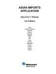
Tooth Contact
Gear tooth contact pattern check is necessary t o
verify correct relationship between ring gear and
drive pinion.
Hypoid gear set which are not positioned properly
may be noisy, or have short life or both. With a
pattern check, the most desirable contact for low
noise level and long life can be assured
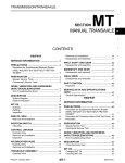
3. Hold companion flange steady by hand and
rotate the ring gear in both directions
1 Thoroughly clean ring gear and drive pinion
teeth.
2. Sparingly apply a mixture of powdered ferric
oxide and oil or equivalent t o 3 or 4 teeth of
ring gear drive side.
SPD308
'
Heel mnmct
SPD357
Usually the pattern will be correct if you have
calculated the shims correctly and the backlash
is correct.
However, in extremely rare cases you will have t o
use trial-and-error processes until you get a good
tooth contact pattern.
The tooth pattern is the best indication of how
well a differential has been set up.
Face contact
TO* contact
To correct. increase thickness of pinion
height adjusting washer in order to bring
drive pinion close t o ring gear
Flank contact
To correct, reduce thickness of pman
height adjusting washer In order to make
drive pinion go away from rmg gear
SPD007
PD-23
ASSEMBLY (Model R200)
Differential Case
1
Clearance between side gear thrust washer and
differential case:
Less than 0 15 mm (0.0059 in)
Install side gears, pinlon mate gears, thrust
washers and thrust block into differential
case
4 Install pinion mate shaft lock pin with a punch
punch
Make sure lock pin IS flush with case
SPD552
2. Fit pinion mate shaft t o differential case
so that it meets lock pin holes.
SPD030
5 Apply gear oil t o gear tooth surfaces and thrust
surfaces and check t o see they turn properly.
Gear 011
SPD553
3 Adjust clearance between rear face of side
gear and thrust washer by selecting side gear
thrust washer (Refer t o S D S )
W
SPD322
SPD029
PD-24
ASSEMBLY (Model R200)
-
Differential Case (Cont'd)
6. Apply locking agent [Locktite (stud lock) or
1
equivalent] t o contacting surfaces of ring gear
and differential case, then place differential
case on ring gear
Differential Carrier
Press-fit front and rear bearing outer races
with Tools
Pinion rear bearing
P l n m front bearing
outer race
7
SPDSOO
7 Apply locking agent [Locktite (stud lock) or
equivalent] t o ring gear bolts, and install them.
Tighten b o l t s in a criss-cross fashion, lightly tap
ping bolt head with a hammer.
8 Press fit side bearing inner races on differential
case with Tool.
SPD555
Tool number:
@ ST30611000 (525742-1)
@ ST30621000(
@ ST30613000 (J25742-3)
W
PO353
Tool number:
@ KV38100300 (J25523)
@ ST33061000 (J8107-2)
PD-25
ASSEMBLY (Model R200)
Differential Carrier (Cont'd)
2
Select pinion height adjusting washer and
pinion bearing adjusting washer spacer, referring t o Adjustment.
3. Install pinion height adjusting washer in drive
pinion, and press fit rear bearing inner race in
it with press and Tool
5
Apply multi-purpose grease to cavity a t sealing
lips of oil seal.
Install front oil seal
SPD557
Tool number: KV38100500 (
-
6. Install companion flange, and tighten pinion
SPD377
Toolnumber ST30901000(
-
nut t o specified torque.
)
4. Set drive pinion assembly (as shown in figure
below) in differential carrier and install drive
pinion with press and suitable tool.
Ascertain that threaded portion of drive pinion and
pinion nut are free from oil or grease.
Stop when drive pinion touches bearing.
PD466
Sunable spacer
Tool number. ST31520000
Drive Dinion,
P ~ n m
bearing adlusting washer
P l n m front bearing inner race
ront pdot bearing spacer
Front pilot bearing
SPD556
PD-26
ASSEMBLY (Model R200)
Differential C .rier (Cont'd)
7. Turn drive pinion in both directions several
times, and measure pinion bearing preload.
10 Insert left and right side bearing adjusting
washers in place between side bearings and
carrier.
PD340
SPD558
Tool number.
ST3127S000 (See J25765-A.)
11 Drive in side bearing spacer with Tool
Pinion bearing preload (With front oil seal)
1 13 - 1.72 N m
(11.5 - 17.5 kg-cm, 10.0 - 15.2 in-lb)
When pinion bearing preload is outside the
specifications, replace pinion bearing adjusting
washer and spacer with a different thickness
8
9
Select side bearing adjusting washer
Refer t o Adjustment.
Install differential case assembly with side
bearing outer races into gear carrier.
SPD559
Tool number: KV38100600 (J25267)
PD-27
ASSEMBLY (Model R200)
Differential C
12. Align mark on bearing cap with that on gear
carrier and install bearing cap on gear carrier
rier (Cont'd)
14. Measure ring gear-to-drive pinion backlash
with a dial indicator.
SPD526
SPD513
Ring gear-to-drive pinion backlash:
0.13 - 0.18 mm
(0.0051 - 0.0071 in)
13. Apply multi-purpose grease t o cavity at sealing
lips of oil seal
Install side oil seal.
0
If backlash is too small, decrease thickness of
right shim and increase thickness of l e f t shim
by the same amount.
If backlash is too great, reverse the above procedure
Never change the total amount of shims as it will
change the bearing preload.
15. Check total preload with Tool
When checking preload, turn drive pinion in both
directions several times to set bearing rollers.
L Tool
SPD560
Tool number. KV38100200 (
-
)
.
PD340
Tool number: ST3127SOOO (See 525765-A.)
Total preload:
1.23 2.30 N m
(12.5 - 23.5 kg-cm, 10.9 - 20.4 in-lb)
-
PD-28
ASSEMBLY (Model R200)
Differential C .rier (Cont'd)
If preload is too great, add the same amount of
shim t o each side.
If preload IS too small, remove the same
amount of shim t o each side
Never add or remove a different number of shims
for each side as it will change ring gear-to-drive
pinion backlash.
If the backlash varies greatly when the runout
of the ring gear is within a specified range, the
hypoid gear set or differential case should be
replaced
18 Check tooth contact
Refer t o Adjustment
19 Install rear cover and gasket
SPD561
16 Recheck ring gear-to-drive pinion backlash
because increase or decrease in thickness of
shims will cause change of ring gear-to-pinion
backlash
17 Check runout of ring gear with a dial indicator
Runout limit:
0.05 mm (0.0020 in)
I f backlash varies excessively in different
places, the variance may have resulted from
foreign matter caught between the ring gear
and the differential case.
PD-29
SERVICE DATA AND SPECIFICATIONS (S.D.S.)
Propeller Shaft
GENERAL SPECIFICATIONS
Unit mm (("1
I
VG30E without turbo
Applied model
I
2 seater
M/T
VG30E turbo
A/T
M/T
2+2 seater
VG30E without turbo
A/T
M/T
VG30E turbo
A/T
AIT
2S71A
Propeller shaft model
I
Number of jmnts
2
Sleeve type
Coupling method with transmissionI
D16tance between yokes
I
71 (2801
Shell type (no"-disassembly type1
Type of journal bearing
I
Shaff outer diameter
75 12 951
SERVICE DATA
Unit
mm
I d
2S71A
Model
0 6 IO 0241
Propeller shaft runout limit
TIGHTENING TORQUE
umt
Nm
kg-m
ft-lb
Shaft to companion
flange bolts
39-44
40-45
29-33
0 (01
Journal axial play
Differenl 11 Carrier
SERVICE DATA
GENERAL SPECIFICATIONS
Applled model
VG30E
without turbo
Fmal drive model
Ring gear pitch
diameter
I
VG30E turbo
I
R200
Drive pinion bearing preload
adlusting method
R200
mm (in1
Final drive model
200 17 87)
Adjusting spacer and warher
Drive pinion preload
(With front 0 1 1 seal1
N m lkgcm, in-lbl
113 172
(11 5 - 1 7 5 . 1 0 0 - 1 5 2 1
Drive pinion preload
IWithout front 011 real)
N m lkgcm, in-lb)
1 0 - 1 3 110- 13,8 7.11 3)
Gear ratio
Number of teeth
1Rmg gearIDrive pinion)
011
capaoty lapprox )
P IUS pt. Imp ptl
37/10
39/11
1 3 12-3/4,2-1/4)
Total preload
Nmlkgcm,~n-lbl
Side bearing adjusting method
123-230
1125-235.109-2041
Shim
Backlash
orlve Pl"l0" to rung gear
0 13 - 0 18 IO 0051 -000711
mm (in1
Side gear to pinion mate gear
IClearance between side gear
to differential case1 mm Inn1
Ring gear runout limit mm
PD-30
I d
Less than 0 15 I O 0059)
0 05 IO 0020)
SERVICE DATA AND SPECIFICATIONS (S.D.S.)
Differential Carrier (Cont'd)
Pinion height adjusting washer
Side bearing adjusting washer
Thickness mrn I i n l
Part No
Thickness mm (tnl
Part No
3 09 10 1217)
3 12 I O 1228)
3 15 10 12401
3 18 10 1252)
3 21 IO 12641
3 24 10 12761
3 27 IO 1287)
3 30 10 12991
3 33 10 13111
3 36 IO 1323)
3 39 I O 1335)
3 42 (0 13461
3 45 I O 1358)
3 48 IO 13701
3 51 10 13821
3 54 I O 13941
3 57 10 1406)
3601014171
3 63 10 1429)
3 66 I O 1441)
0 05 10 00201
0 07 10 00281
38154-P6017
38154 P6018
38154-P6019
38154-P6020
38154-P6021
38154-P6022
381 54-P6023
38154-P6024
38154-P6025
38154.P6026
381 54-P6027
38154-P6028
38154-P6029
381 54-P6030
38154-P6031
38154-P6032
38154.P60.33
38154P6034
38154-P6035
38154-P6036
38453-28500
3845428500
2 00 (007871
2 05 IO 0807)
2 10 IO 0827)
2 15 IO 08461
38453-N3100
38453-N3101
38453 N3102
38453N3103
38453-N3104
38453-N3105
38453-N3106
38453.N3107
38453.N3108
38453-N3109
38453 N3110
38453.N3111
38453-N3112
2 20 IO 0866)
2 25 10 08861
2 30 10 0906)
2 35 10 09251
2 40 10 09451
2 45 10 09651
2 50 10 09841
2 55 10 10041
2 60 10 1024)
Side gear thrust washer
Thickness rnm lml
Part No
0 75.0 80 IO 0295 - 0 03151
0 80 - 0 85 IO 0315.0 0335)
0 85 - 0 90 I O 0335.0 0354)
38424-N3100
38424-N3101
38424 N3102
38424-N3103
0 90 - 0 95 (00354.0 0374)
TIGHTENING TORQUE
R200
Type
Drive pinion bearing preload adjusting washer
Thickness rnm
Iml
3 80 - 3 82 (01496 - 0 15041
3 8 2 - 3 84 (01504- 0 15121
3 84.3 86 (0 1512 - 0 15201
3 8 6 . 3 88 (01520- 0 1528)
3 8 8 - 3 90 I O 1528- 0 1535)
390-392101535-015431
3 9 2 - 3 94 (01543.0 1551)
3 94.3 96 10 1551 - 0 15591
3 96 - 3 98 10 1559- 0 1567)
3 9 8 - 4 00 I O 1567.0 1575)
4 0 0 - 4 02 (01 5 7 5 - 0 15831
4 0 2 . 4 04 I O 1583.0 15911
4 04 - 4 06 10 1591 - 0 15981
4 0 6 . 4 08 I O 1598 - 0 1606)
4 0 8 - 4 10 10 1606 - 0 1614)
Part No
38125-61001
38126-61001
38127-61001
381 2861001
38129-61001
38130-61001
38131-61001
38132-61001
38133-61001
38134-61001
38135-61001
38136-61001
38137-61001
38138-61001
38139-61001
U"lt
Nm
kg-m
ft-lb
Final drive Installation
Drive shaft to rear axle
VG30E without
turbo
VG30E turbo
39 - 49
4- 5
29.36
59-69
6-7
43.51
88-118
90.120
65-87
29-39
59-78
3-4
6-8
22 - 29
43.58
59 - 78
6- 8
43.58
186.294
19.30
137 -217
69.78
7 0.8 0
51 . 5 8
1Jz-152
135-155
98-112
88 - 98
9 0. 10 0
65.72
Rear cover to
mounting ms~lator
Mounting insulator
t o body
Bolt
NUt
Differential carrier to
s~spensionmember
Final drive assembly
Drive pinion nut
Ring gear bolt [using
Locktite lrtud lock) or
equivalent1
VG30E without
turbo
VG30E turbo
Drive pinion bearing preload adjusting spacer
Length
mrn Iml
55 10 (2 1693)
554012 18111
55 70 (2 1929)
56 00 (2 20471
56 25 I2 2146)
Side bearing cap bolt
Part No
3816&84002
38165-84003
38165-84004
3816561001
38166-61001
PD-31
Reareaver fixing bolt
16 - 24
16-24
12-17
Companion flange to
propeller shaft fixing
bo t
39.44
4 0.4 5
29 - 33
Filleranddrainplug
59-98
6-10
43 - 72
SPECIAL SERVICE TOOLS
~
Tool number
(Kent-Moore No
Tool name
-
)
Drive pinion flange wrench
ST30613000
(J25742-3)
Drift
KV38100800
I
-
Tool
ST30611000
(J25742-1)
Drift
ST31520000
(
Tool number
(Kent-Moore No )
Tool name
Tool
)
Differential attachment
Equivalent tool
(J25604-01)
ST30621000
(
-
)
Drift
KV38100200
ST0501S000
(J26023)
Engine stand
@ ST05011000
(
@
-
(
1
-
(
)
-
)
(
-
)
Base
ST3306SOOl
Diff side bearing puller set
@ ST33051001
(
-
1
ST33290001
(J25810-A)
Side bearing outer race
puller
ST3090S000
(
-
Gear carrier front oil seal
drift
Base
Drive pinion rear inner race
puller set
@ ST30031000
(J22912-01)
Puller
@ ST30901000
1
KV38100500
Engine stand
ST05012000
(
-
Gear carrier side oil seal
drift
w
KV38100300
(J25523)
Diff side bearing drift
KV38100401
(
)
Pilot bearing drift
KV38100600
(J25267)
Side bearing spacer drift
)
Body
@ ST33061000
(J8107-2)
Adapter
HT72400000
(
-
)
Slide hammer
PD-32
57
SPECIAL SERVICE TOOLS
Tool number
(Kent-Moore No
Tool name
1
ST3127SOOO
(See J25765-A)
Preload gauge
@ GG91030000
(J25765-A)
Torque wrench
@ HT62940000
(
@
-
)
Tool number
(Kent-Moore No )
Tool name
Tool
Tool
(J25269-25)
Lead preload washers
(Pkg of 5)
(52526926)
Bearing preload adapter
Socket adapter
HT62900000
(
-
1
Socket adaoter
(J8001-M)
Metric dial indicator set
(JBOOlS dial indicator
(J25269-29)
Front bearing pilot support
U
(J25269-32)
Instructions
only)
(J25269-8)
Pinion height 5 preload
gauge set
@ 525269-23
Bolt 5 nut
@ J23597-1
Arbor (Long plunger)
Use with 523597-1
(525407-01)
Side bearing measuring set
consists of
@ J25407-1
4-step gauge block
@ J25407-2
Base plate
@ J25407-3
Weight block
(J25269-1)
Gauge plate
(J26099-A)
Differential shim organizer
(525269-2)
Rear pinion bearing pilot
(J26335)
Differential filler plug
wrench
(J25269-3)
Front pinion bearing pilot
(J252694)
Side bearing discs
(2 Req'd)
PD-33
0
Courtesy Nissan
1777 North Central Expressway
Richardson, TX 75080
(800)527-1909
NISSAN FACTORY SERVICE MANUAL CDROM END-USER LICENSE AGREEMENT
NOTICE TO USER: THIS IS A CONTRACT. BY PURCHASING AND USING THE SERVICE MANUAL ON
CDROM, YOU ACCEPT ALL THE TERMS AND CONDITIONS OF THIS AGREEMENT.
This End User License Agreement accompanies the Service Manual on CDROM product and related explanatory
materials. Please read this Agreement carefully. By purchasing and using the Service Manual on CDROM, you are
implying that you have carefully read, agree with, and will adhere to the conditions set forth in this agreement. If
you do not wish to accept the terms of this End User Agreement please do not use the Service Manual on CDROM.
You will not be permitted to use the Service Manual on CDROM without consenting to this end user agreement.
Upon your acceptance of this Agreement, Courtesy Nissan grants to you a nonexclusive license to use the Service
Manual on CDROM, provided that you agree to the following:
USE OF SOFTWARE
You may install the contents of the CD on a hard disk or other storage device for personal use only. Each Service
Manual on CDROM comes with a single user license. Under no circumstances should the contents of the Service
Manual CDROM be placed on a server for purposes of distributing or allowing access to the material over a
network.
COPYRIGHT AND TRADEMARK RIGHTS
The Service Manual CDROM is owned by Courtesy Nissan and its structure and organization, all graphics and
coding are considered intellectual property of Courtesy Nissan. The Service Manual on CDROM is also protected by
United States Copyright Law and International Treaty provisions. This Agreement does not grant you any
intellectual property or resale rights to the Service Manual CDROM.
RESTRICTIONS
You agree not to modify, adapt, translate, reverse engineer, decompile or disassemble the PDF file on the Service
Manual CDROM. The Service Manual on CDROM is licensed and distributed by Courtesy Nissan for single user
utilization of its contents only. Licensed users will be permitted to use the contents of the Service Manual CDROM
for multimedia presentation to an audience from a single machine using a large display or projection device but the
Service Manual CDROM may not otherwise be distributed, sold to or made accessible to multiple users.
NO WARRANTY
The software is being delivered to you AS IS and Courtesy Nissan makes no warranty as to its use or performance.
COURTESY NISSAN DOES NOT AND CANNOT WARRANT THE PERFORMANCE OR RESULTS YOU
MAY OBTAIN BY USING THE SERVICE MANUAL CDROM OR DOCUMENTATION, NOR MAKES ANY
WARRANTIES, EXPRESS OR IMPLIED, AS TO NONINFRINGEMENT OF THIRD-PARTY RIGHTS,
MERCHANTABILITY, OR FITNESS FOR ANY PARTICULAR PURPOSE. IN NO EVENT WILL COURTESY
NISSAN BE LIABLE TO YOU FOR ANY CONSEQUENTIAL, INCIDENTAL, OR SPECIAL DAMAGES FOR
ANY REASON.
Courtesy Nissan
1777 North Central Expressway
Richardson, TX 75080
(800)527-1909
GOVERNING LAW AND GENERAL PROVISIONS
This Agreement will be governed by the laws of the State of Texas, USA, excluding the application of its conflicts
of law rules. This Agreement will not be governed by the United Nations Convention on Contracts for the
International Sale of Goods, the application of which is expressly excluded. If any part of this Agreement is found
void and unenforceable, it will not affect the validity of the balance of the Agreement, which shall remain valid and
enforceable according to its terms. You agree that the Service Manual on CDROM will not be shipped, transferred
or exported into any country or used in any manner prohibited by the United States Export Administration act or any
other export laws, restrictions or regulations. This Agreement shall automatically terminate upon failure by you to
comply with its terms. This Agreement may only be modified in writing signed by and authorized officer for
Courtesy Nissan.
Courtesy Nissan
1777 North Central Expressway
Richardson, TX 75080
USA
YOUR ACCEPTANCE OF THE FOREGOING AGREEMENT IS IMPLIED UPON PURCHASING AND USING
THE SERVICE MANUAL CDROM.