1
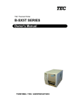
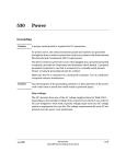
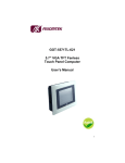
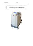
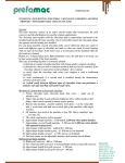
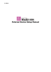
Installation Guide
Flame Ionization Detector on a 6850 GC
Accessory G2621
© Agilent Technologies 2000
Safety Information
Safety Symbols
All Rights Reserved. Reproduction,
adaptation, or translation without
permission is prohibited, except as allowed
under the copyright laws.
The Agilent Technologies Flame Ionization
Detector meets the following IEC
(International Electrotechnical Commission)
classifications: Safety Class 1, Transient
Overvoltage Category II, and Pollution
Degree 2.
Warnings in the manual or on the
instrument must be observed during all
phases of operation, service, and repair of
this instrument. Failure to comply with these
precautions violates safety standards of
design and the intended use of the
instrument. Agilent Technologies assumes
no liability for the customer’s failure to
comply with these requirements.
Part number G2621-90107
First Edition, DEC 2000
Replaces Part No. G2621-90100 Operating
and Service Manual.
HP® is a registered trademark of
Hewlett-Packard Co.
Printed in USA
This unit has been designed and tested in
accordance with recognized safety
standards and designed for use indoors. If
the instrument is used in a manner not
specified by the manufacturer, the
protection provided by the instrument may
be impaired. Whenever the safety protection
of the Agilent G2621 has been
compromised, disconnect the unit from all
power sources and secure the unit against
unintended operation.
Refer servicing to qualified service
personnel. Substituting parts or performing
any unauthorized modification to the
instrument may result in a safety hazard.
Disconnect the AC power cord before
removing covers. The customer should not
attempt to replace the battery or fuses in
this instrument.
WARNING
A warning calls attention to a condition or
possible situation that could cause injury to
the user.
CAUTION
A caution calls attention to a condition or
possible situation that could damage or
destroy the product or the user’s work.
Sound Emission Certification for Federal
Republic of Germany
Sound pressure Lp < 68 dB(A)
During normal operation
At the operator position
According to ISO 7779 (Type Test)
Schallemission
Schalldruckpegel LP < 68 dB(A)
Am Arbeitsplatz
Normaler Betrieb
Nach DIN 45635 T. 19 (Typprüfung)
Agilent Technologies, Inc.
2850 Centerville Road
Wilmington, DE 19808-1610
USA
Installing a Flame Ionization Detector on an
Agilent 6850 Gas Chromatograph
This kit contains:
Kit G2621-64000
Qty.
Flame ionization detector system
1
Performance evaluation sample kit
1
Nut warmer cup assembly
1
Nut warmer insulation
1
Wrist strap, disposable, large
1
Screw, M4 x12 mm, pan head
3
Installation sheet (this document)
1
Copyright© 2000
Agilent Technologies
Printed in USA Dec 2000
Agilent Part No. G2621-90107
1
Installing a Flame Ionization Detector on an Agilent 6850 Gas Chromatograph
The FID detector assembly is a factory-assembled, tested, and calibrated
unit. Disassembly of the unit is not required for installation.
Ribbon cable
Heater/sensor cable
FID assembly
Ignitor cable
Nutwarmer
Flow module cable
Insulation
(3 pieces)
Screws
Flow module
FID signal board
Tools Required
Torx™ T-20 driver
Flat blade screwdriver
Open end wrenches
Safety Information
Before continuing, read the safety information on your Agilent 6850 Gas
Chromatograph User Information CD-ROM.
2
Installing a Flame Ionization Detector on an Agilent 6850 Gas Chromatograph
Prepare for Installation
WARNING
Hydrogen gas is flammable and potentially explosive. Before replacing the
manifold, turn off the hydrogen gas at the source.
WARNING
Before proceeding, turn off the oven and any heated zones and let them cool
down. Turn off all detector gases at their supply, then turn off the main
power switch and unplug the power cord.
1.
Open the lid. If a column is installed, disconnect it at the detector end.
Remove the nut warmer, insulation, and capillary adapter, if present.
Close the lid.
2.
Turn all gases off at their sources. Disconnect the carrier and detector
gas tubing from the back panel of the instrument.
Disconnect gas supply tubing
from these fittings
BNC
BNC
To Base - T
To Base - T
Local Talk
Local Talk
3
Installing a Flame Ionization Detector on an Agilent 6850 Gas Chromatograph
Remove the Lid Top Cover
Remove vent tubing,
if present
Lid top cover, without
valve box accessory
Remove T-20 Torx™
screws (8 places)
Remove detector
cover, if desired
Remove the lid top cover.
Disconnect the Heater/Sensor Cable
1.
Trace the detector heater/sensor cable to the wiring harness near the
injection part cooling fan.
2.
Disconnect the cable at the connector.
Raise the Lid to the Service Position
1.
4
Open the lid. Locate the counterbalance cam in the left rear corner
under the lid. Loosen the screw on the right side of the cam. This allows
the stop plate to drop down.
Installing a Flame Ionization Detector on an Agilent 6850 Gas Chromatograph
Cam follower
Stop plate
Screw
Counterbalance cam
WARNING
2.
Raise the lid until it is stopped by the safety cable.
3.
Raise the stop plate and tighten the screw to lock the lid in the upright
service position.
The lid is heavy. Always lock the lid when it is in the service position.
5
Installing a Flame Ionization Detector on an Agilent 6850 Gas Chromatograph
Remove the Detector Electronics Cover
1.
Loosen the two bottom screws on the detector electronics cover.
Remove screw
Detector electronics cover
Loosen screws
6
2.
Remove the top screw on the cover.
3.
Lift and remove the detector electronics cover.
Installing a Flame Ionization Detector on an Agilent 6850 Gas Chromatograph
4.
Loosen the signal board clamp.
Ribbon cable
Signal board
(FID shown)
Signal board clamp
A/D converter board
5.
Unplug the signal board from the A/D converter board.
6.
Disconnect the wiring from the signal board.
FID – Disconnect the ribbon cable. Unplug the ignitor cable. Pass both
cables through the hole to the top side of the lid.
The ribbon cable connector will not pass through the rubber grommet in
the hole. Use a small screwdriver to push the grommet to the top of the
lid; the cables will now fit through the hole.
7
Installing a Flame Ionization Detector on an Agilent 6850 Gas Chromatograph
Ribbon cable connector
Ignitor cable connector
TCD – Unplug the two-wire switching valve cable at the connector. To
release the PRT and filament wires, press down on the orange tabs. Pass
the disconnected wires through the hole to the top side of the lid.
Switching valve cable connector
PRT wires
Filament wires
8
7.
Lower the stop plate on the lid cam. Pull the lid forward until the cam
follower rests on the curved surface of the cam. Leave the stop plate in
the "down" position.
8.
Close the lid.
Installing a Flame Ionization Detector on an Agilent 6850 Gas Chromatograph
Remove the Existing Detector and Flow Manifold
1.
On the top of the lid, loosen the connector cover plate screws and
remove the plates.
Cover plate screws (4)
Gas manifold
(FID shown)
Manifold mounting
screws
Gas fittings
2.
Disconnect the gas fittings. The figure shows the FID manifold; the TCD
manifold is similar but has only one gas connection.
3.
Trace the ribbon cable from the flow manifold and disconnect it from
the harness.
4.
Remove the three manifold mounting screws.
5.
Remove the screws holding the detector assembly in place.
9
Installing a Flame Ionization Detector on an Agilent 6850 Gas Chromatograph
FID – Remove four mounting screws.
Mounting screws
(one concealed)
TCD – Remove two mounting screws.
Mounting
screws
6.
WARNING
The fibrous insulation material can cause irritation to the skin, eyes, and
mucous membranes. Always wear gloves when working with the insulation.
If the insulation is flaky/crumbly, wear protective eyewear and respirator.
7.
10
Lift the detector and flow manifold out of the lid as a unit.
Remove any insulation that may be in the hole under the detector.
Installing a Flame Ionization Detector on an Agilent 6850 Gas Chromatograph
Install the Flame Ionization Detector and Flow Manifold
1.
Place the flame ionization detector and flow manifold in position in the
lid. Check that no wiring or tubing is trapped under either assembly.
Ignitor cable
Heater/sensor cable connection
Screws (4 places,
one not visible)
2.
Secure the detector assembly to the lid with four screws.
3.
Secure the manifold to the lid with three screws.
4.
Plug the manifold ribbon cable into its connector.
5.
Install the two connector cover plates.
6.
Connect the gas supply lines as shown below. If the previous detector
was a TCD, the A and H lines should be folded up in the space under the
fittings. Unfold them, being careful to avoid kinks, and feed them up to
the manifold area.
Connect the line marked A here
Connect the line marked M here
Connect the line marked H here
11
Installing a Flame Ionization Detector on an Agilent 6850 Gas Chromatograph
Connect the Heater/Sensor Cable
Connect the detector heater/sensor cable to the wiring harness near the
injection part cooling fan.
Connect the other Leads and the Signal Board
1.
Raise the lid to the service position and lock it in place by raising the
stop plate.
2.
There is an oblong hole through the lid near the left rear corner of the
FID assembly. If there is a grommet in the hole, remove it. Pass the
ignitor cable and the ribbon cable through the hole into the signal board
space.
3.
Use a small screwdriver to install the grommet around the cables in the
oblong hole.
4.
Connect the ribbon and ignitor cables to the signal board.
Ribbon cable connector
A/D converter
board connector
12
Ignitor connector
5.
Turn the signal board over, plug it into the A/D converter board, and
secure it with the signal board clamp.
6.
Install the detector electronics cover and tighten all three screws.
7.
Lower the stop plate on the lid cam. Pull the lid forward until the cam
follower rests on the curved surface of the cam. Raise the stop plate
behind the cam follower and tighten the screw.
8.
Close the lid. Be sure that the folded gas lines do not interfere with it.
Installing a Flame Ionization Detector on an Agilent 6850 Gas Chromatograph
9.
Install the lid top cover.
Finishing Up
1.
Install the capillary adapter, if used.
2.
Restore the column connection.
3.
Restore carrier and other gases to the instrument.
4.
Restore power.
5.
Apply your normal operating pressures. Leak-check the manifold, back
panel, and column fittings.
13
14
Printed on recycled paper.
This product is recyclable.
Agilent Technologies, Inc.
Printed in USA Dec 2000
G2621-90107