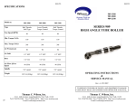
1
Operation & Service Manual
823157
2/01
75 Series Nutrunners
75
X
N
X
L
-
XX
X -
X
Series:
Output Drive:
4
1/2"
5
5/8"
6
3/4"
75
Rotation:
Non Reversible
Reversible
R
Nutrunner:
Angle Terminations:
Clutch Designation:
A
S
Built-in Socket
(Specify Size)
T
Threaded Spindle
V VHD Hold & Drive
X
Clecomatic
Stall Type
Handle:
L
Lever
Gear Train Designation:
2
4
3
6
For additional product information visit our website at http://www.clecotools.com
NORTH AMERICA
CooperTools
P.O. Box 1410
Lexington, SC 29071
EUROPE
Cooper Power Tools GmbH & Co.
Postfach 30
D-73461 Westhausen
1
Safety Recommendations
For your safety and the safety of others, read and understand the
safety recommendations and operating instructions before operating a nutrunner.
the air hose of accumulated dust and moisture. Before connecting
a tool to the air hose or removing a tool from service or changing
sockets, make sure the air line is shut off and drained of air. This will
prevent the tool from operating if the throttle is accidently engaged.
Always wear protective equipment:
!
!
WARNING
Impact resistant eye protection
must be worn while operating
or working near this tool.
For additional information on eye protection and face protection,
refer to Federal OSHA Regulations, 29 Code of Federal Regulations, Section 1910.133., Eye and Face Protection, and American
National Standards Institute, ANSI Z87.1, Occupational and Educational Eye and Face Protection. Z87.1 is available from the American
National Standards Institute, Inc., 11 West 42nd Street, New York,
NY 10036.
!
CAUTION
CAUTION
When using right angle nutrunners, be sure the throttle is positioned
relative to the angle head so that the throttle will not become wedged
against an adjacent object in the "ON" position due to torque
reaction. The angle head may be repositioned with respect to the
lever to accommodate proper location for task. If tool is to be
reversed, locate throttle lever in a neutral position that will prevent
entrapment. Refer to operating instructions for additional information.
It is essential for safe operation that any operator of a nutrunner use
good balance, sure footing, and proper posture in anticipation of a
torque reaction.
Tools with clutches can stall rather than shut-off if adjusted over
maximum power output of tool, or if there is a drop in air pressure.
Operator must then resist stall torque until throttle is released.
Personal hearing protection is
recommended when operating
or working near this tool.
Hearing protection is recommended in high noise areas 85 dBA or
greater. The operation of other tools and equipment in the area,
reflective surfaces, process noises and resonant structures can
substantially contribute to, and increase the noise level in the area.
Excessive air pressure above 90 PSIG and worn motor components
can also increase sound level emitted by tool. Proper hearing
conservation measures, including annual audiograms and training
in the use and fit of hearing protection devices may be necessary.
For additional information on hearing protection, refer to Federal
Regulations, Section 1910.95, Occupational Noise Exposure, and
American National Standards Institute, ANSI S12.6, Hearing Protectors.
Cleco nutrunners are designed to operate on 90 psig (6.2 bar)
maximum air pressure. If the tool is properly sized and applied,
higher air pressure is unnecessary. Excessive air pressure increases the loads and stresses on the tool parts, sockets, and
fasteners and may result in breakage. Installation of a filter-regulator-lubricator in the air supply line ahead of the tool is recommended.
Before the tool is connected to the air supply, check the throttle for
proper operation (i. e., throttle moves freely and returns to closed
position). Being careful not to endanger adjacent personnel, clear
2
Spindle Rotation
Torque Reaction
Tool balance arms are available to absorb the torque reaction of the
tool while balancing the weight of the tool for improved ergonomic
applications.
Safety Recommendations
!
WARNING
Repetitive work motions and/or vibration
may cause injury to hands and arms.
Use minimum hand grip force consistent
with proper control and safe operation.
Keep body and hands warm and dry.
Avoid anything that inhibits blood circulation.
Avoid continuous vibration exposure.
Keep wrists straight.
Avoid repeated bending of wrists and hands.
Some individuals may be susceptible to disorders of the hands and
arms when performing tasks consisting of highly repetitive motions
and/or exposure to extended vibration. Cumulative trauma disorders
such as carpal tunnel syndrome and tendonitis may be caused or
aggravated by repetitious, forceful exertions of the hands and arms.
Vibration may contribute to a condition called Raynaud's Syndrome.
These disorders develop gradually over periods of weeks, months,
and years. It is presently unknown to what extent exposure to
vibrations or repetitive motions may contribute to the disorders.
Hereditary factors, vasculatory or circulatory problems, exposure to
cold and dampness, diet, smoking and work practices are thought to
contribute to the conditions.
Any tool operator should be aware of the following warning signs and
symptoms so that a problem can be addressed before it becomes a
debilitating injury. Any user suffering prolonged symptoms of tingling, numbness, blanching of fingers, clumsiness or weakened
grip, nocturnal pain in the hand, or any other disorder of the
shoulders, arms, wrists, or fingers is advised to consult a physician.
If it is determined that the symptoms are job related or aggravated
by movements and postures dictated by the job design, it may be
necessary for the employer to take steps to prevent further occurrences. These steps might include, but are not limited to, repositioning the workpiece or redesigning the workstation, reassigning workers to other jobs, rotating jobs, changing work pace, and/or changing
the type of tool used so as to minimize stress on the operator. Some
tasks may require more than one type of tool to obtain the optimum
operator/tool/task relationship.
The following suggestions will help reduce or moderate the effects
of repetitive work motions and/or extended vibration exposure:
• Use a minimum hand grip force consistent with proper
control and safe operation
• Keep body and hands warm and dry (cold weather is
reported to be a major factor contributing to Raynaud's
Syndrome)
• Avoid anything that inhibits blood circulation
—Smoking Tobacco (another contributing
factor)
—Cold Temperatures
—Certain Drugs
Avoid
Extension
OK
Neutral
Avoid
Flexion
Avoid
Radial Deviation
OK
Avoid
Neutral
Ulnar Deviation
• Tasks should be performed in such a manner that the
wrists are maintained in a neutral position, which is not
flexed, hyperextended, or turned side to side.
• Stressful postures should be avoided — select a tool
appropriate for the job and work location
• Avoid highly repetitive movements of hands and wrists, and continuous vibration exposure (after each period of operation, exer
cise to increase blood circulation)
• Keep tool well maintained and replace worn parts
Work gloves with vibration reducing liners and wrist supports are
available from some manufacturers of industrial work gloves. Tool
wraps and grips are also available from a number of different
manufacturers. These gloves, wraps, and wrist supports are designed to reduce and moderate the effects of extended vibration
exposure and repetitive wrist trauma. Since they vary widely in
design, material, thickness, vibration reduction, and wrist support
qualities, it is recommended that the glove, tool wrap, or wrist support
manufacturer be consulted for items designed for your specific
application. WARNING! Proper fit of gloves is important. Improperly fitted gloves may restrict blood flow to the fingers and can
substantially reduce grip strength.
3
Safety Recommendations
203185-4
!
WARNING
Wear respirator where
necessary.
Drilling or other use of this tool may produce hazardous fumes and/
or dust. To avoid adverse health effects, utilize adequate ventilation
and/or a respirator. Read the material safety data sheet of any
cutting fluids or materials involved in the drilling process.
!
CAUTION
• Drill bits are sharp. Handle them carefully to avoid injury.
• The cutting tool maximum speed rating must equal or exceed
the rated speed of the tool.
• Use the appropriate size chuck key to securely tighten a drill bit
in the chuck.
• Use precautions when drilling because of the possibility of the
cutting tool bending or breaking.
• High reaction torque may be experienced by the operator with
any drill at breakthrough.
• Drill bits or accessories not centered properly in the chuck can
cause excessive wobble or vibration.
4
203185
203289
WARNING
!
OVER
Repetitive work motions and/or vibration
can cause injury to hands and arms.
Use minimum hand grip force consistent with
proper control and safe operation.
Keep body and hands warm and dry.
Avoid anything that inhibits blood circulation.
Avoid continuous vibration exposure.
Keep wrists straight.
Avoid repeated bending of wrists and hands.
CAUTION
!
Personal hearing protection is
recommended when operating
or working near this tool.
READ
OPERATING
INSTRUCTIONS
Hearing protection is recommended in high noise
areas (above 85 dBA). Close proximity of other
tools, reflective surfaces, process noises, and
resonant structures can substantially contribute
to the sound level experienced by the user.
Follow good machine shop practices. Rotating shafts and moving
components can entangle and entrap, and can result in serious
injuries. Never wear long hair, loose-fitting clothes, gloves, ties, or
jewelry when working with or near a drill of any type.
WARNING
Warning Labels
The warning labels found on these tools are an essential part of this
product. Labels should not be removed. Labels should be checked
periodically for legibility. Replace warning labels when missing or
when the information can no longer be read. Replacement labels
can be ordered as any spare part.
!
Do not wear loose fitting clothes,
long hair, gloves, ties or jewelry.
This information is a compilation of general safety practices obtained
from various sources available at the date of production. However,
our company does not represent that every acceptable safety
practice is offered herein, or that abnormal or unusual circumstances may not warrant or require additional procedures. Your work
may require additional specific safety procedures. Follow these
procedures as required by your company.
Impact resistant eye protection
must be worn while operating
or working near this tool.
WARNING
Read Operating Instructions carefully. Follow
the Safety Recommendations for your safety
and the safety of others.
!
For more information on the safe use of portable air tools, see the
latest edition of ANSI B186.1, Safety Code for Portable Air Tools,
available from the American National Standards Institute, Inc. 11
West 42nd Street, New York, NY 10036.
Do not remove this tag until
the operator of this tool has
read these safety precautions.
ADDITIONAL SAFETY RECOMMENDATIONS FOR USE OF RIGHT
ANGLE DRILLS
OPERATING INSTRUCTIONS
The No. 75 Right Angle Nutrunner is designed to operate on
90 PSIG (6.2 bar) air pressure using a 1/2" hose up to 8 ft. in
length.
IMPORTANT: The reaction bracket, No. 202484, must fully
engage the spline on the right angle head. Position the
bracket forward on the small diameter of the head and then
move it rearward to engage the spine.
75 CLECOMATIC NUTRUNNERS
The 75 Clecomatic Nutrunner is designed to operate on 90
PSIG air pressure, but does not depend on controlled air
pressure to maintain accurate torque. Accurate torque is
achieved by setting the Clecomatic clutch to the desired
torque on the application. The tool will shut off automatically
at this torque. Releasing the throttle will allow the tool to reset
for the next cycle.
3/4" or larger hose should be connected to the 1/2" hose.
The air hose should be cleared of accumulated dirt and
moisture, then one (1) teaspoonful of 10W machine oil
should be pou- red into the tool's air inlet before connecting
the hose to the tool.
LUBRICATION
An automatic in-line filter-lubricator is recommended as it
increases tool life and keeps the tool in sustained operation.
The in-line lubricator should be regularly checked and filled
with a good grade of 10W machine oil. Proper adjustment
of the in-line lubricator is performed by placing a sheet of
paper next to the exhaust ports and holding the throttle open
for approximately 30 seconds. The lubricator is properly set
when a very light stain of oil collects on the paper. Excessive
amounts of oil should be avoided.
Application of the tool should govern how frequently it is
greased. It is recommended that the idler gears and right
angle gears receive a generous amount of NLGI 2-EP
grease through the grease fittings after 40 hours of operation.
CLECOMATIC CLUTCH ADJUSTMENT
STORAGE
Rotate the adjustment cover until the adjustment slot is
uncovered. With the angle head end of the tool facing away,
use a 5/32" diameter pin to rotate the adjusting nut clockwise
to increase the torque setting and counterclockwise to decrease the setting. After adjustment, rotate the cover over the
slot.
!
In the event that it becomes necessary to store the tool for
an extended period or time (overnight, weekend, etc.), it
should receive a generous amount of lubrication at that time
and again when returned to service. The tool should be
stored in a clean and dry environment.
CAUTION
If the clutch is adjusted over the maximum power output of the
tool, the clutch will not function and the tool will operate like a
stall-type tool. Also, if the tool is being operated at its upper
torque limits, a drop in air pressure could cause the clutch not
to function due to a loss of motor power and the tool will
function like a stall type tool. If the tool stalls the operator must
resist the stall torque until he releases the throttle.
OPERATIONAL CHECK: Grip tool securely and be prepared
to counteract stall torque in case clutch is improperly adjusted. Use proper reaction bar. THIS IS A HIGH TORQUE
TOOL.
75 STALL TYPE NUTRUNNERS
The 75 Stall Type Nutrunner is designed to develop maximum rated torque at 90 PSIG. Torque output is controlled by
a pressure regulator in the air supply line. Adjust the regulator
until the desired torque is reached.
AIR SUPPLY
For maximum performance, use a 1/2" I.D. air hose no longer
than 8' in length. If additional length is required, a
SERVICE INSTRUCTIONS
DISASSEMBLY—GENERAL
Clecomatic Tools
Clamp the flats of the handle in a vise with the tool in a
vertical position.
Using a suitable wrench, loosen (left hand threads) the
clamp nut, No. 869878, and remove the angle head assembly. Unscrew and remove the clutch housing and gear case
assemblies. Clamp the gear case in the vise and unscrew
the clutch housing.
Slip the motor unit out the front of the handle. It may be
necessary to bump the handle on the work bench to loosen
the motor.
5
Stall Type Tools
Motor
Clamp the flats of the handle in a vise with the tool in a
vertical position.
Use a soft faced mallet to drive the rotor out of the front rotor
bearing, No. 847528. This will allow the removal of the front
bearing plate, No. 869923, cylinder, and five (5) rotor
blades, No. 869927, from the rotor, No. 203147. Clamp the
rotor lightly in the vise and unscrew the rotor lock nut, No.
865352. Rest the rear bearing plate on the vise jaws and use
a soft faced mallet to drive the rotor out of the rear rotor
bearing.
Using a suitable wrench, loosen (left hand threads) the
clamp nut, No. 869878, and remove the angle head assembly. Unscrew and remove the gear case assembly.
Slip the motor unit out the front of the handle. It may be
necessary to bump the handle on the work bench to loosen
the motor.
SUBASSEMBLIES DISASSEMBLY
Right Angle Head
Remove the bearing cap lock screw (1/16 hex), No. 867997,
and unscrew (lee hand threads) the bearing cap. Clamp the
square drive in the vise and use a sort mallet to drive the
angle head off. Press the spindle out of the driven gear and
then press the spindle out of the ball bearing.
Unscrew and remove the bearing retainer, No. 869877, and
grease plug, No. 867546. Use a suitable driver to drive the
pinion gear out of the housing.
Clecomatic Clutch
Important: The adjustment cover, No. 869918, retains the
ball spring, No. 869919, and steel ball, No. 842162, and
care should be exercised to prevent their loss.
Use a 5/32" (3.96mm) diameter pin to lower the clutch
adjustment. This will allow the clutch retainer ring, No.
869920, to be removed from the clutch housing. Remove
the clutch assembly from the housing. Use a suitable
bearing puller to remove ball bearing, No. 847022, drive
shaft washer, No. 869918, trip sleeve spring, No. 869918,
and trip sleeve, No. 867670, from the drive shad No.
869915.
NOTE: Trip Plunger, No. 869916, trip plunger spring, No.
867671, and two (2) balls, No. 842161, should also be
removed at this time. Use a sharp pointed instrument to
remove the cam retainer ring, No. 869921, from the ball
retainer, No. 869914. Slip the drive shaft, No. 869915, and
clutch cam, No. 869913, out the rear of the ball retainer, No.
869914.
Gear Case
Slip the entire gear train out the rear of the gear case. The
2nd reduction idler gears may be removed for inspection by
driving the idler gear pins, No. 869908, out the rear of the
spider.
6
Handle
Unscrew the inlet bushing, No. 869933, for inspection of the
throttle components. The air inlet screen, No. 843656,
should be washed in a solvent and blown out in the reverse
of normal airflow. Replace if damaged or clogged.
REASSEMBLY
The tool is reassembled in the reverse order of disassembly. Clean all parts thoroughly in a solvent and inspect for
damage or wear. Check all bearings for wear which can be
detected by excessive end play and/or roughness which
would indicate a brinelled condition. The rotor blades should
be replaced if they measure less than 3/8" (9.5mm) at either
end. All gear teeth, bearings, and pins should receive a
close inspection and be replace if necessary. All gears and
open bearings should receive a generous amount of No. 2
Moly grease during reassembly.
Motor
To assemble the motor, install the rear rotor bearing into the
rear bearing plate. Make sure the outer bearing race is firmly
seated in the bearing plate. Clamp the rotor body lightly in
the vise with the threaded end up and slip the rear bearing
plate assembly onto the rotor shaft far enough for the
bearing lock nut to start. Tighten the lock nut until there is
approximately .0015" clearance between the rotor and
bearing plate. The outer bearing race should be firmly
seated and the rotor bumped forward when checking this
clearance. Pack both rotor bearings with a good grade of
No. 2 Moly grease after assembly of the motor unit.
IMPORTANT: During reassembly of the complete tool, it is
important that the motor be free. After the tool is completely
assembled, the right angle square drive spindle should turn
freely using a small hand wrench. If the spindle does not turn
freely, the motor should be checked for proper spacing. Do
not run the tool until the spindle turns freely. Failure to do this
could result in damage to motor components.
1st REDUCTION GEAR TRAIN REASSEMBLY
- 2 Gear Train (13 Tooth Spider)
21 Tooth idler gears on inner set of gear pins.
- 3 Gear Train (19 Tooth Spider)
21 Tooth idler gears on inner set of gear pins.
- 4 Gear Train (13 Tooth Spider)
17 Tooth idler gears on outer set of gear pins using 16 tooth
pinion on rotor.
- 5 Gear Train (19 Tooth Spider)
17 Tooth idler gears on outer set of gear pins using 16 tooth
pinion on rotor.
Clutch
The clutch is reassembled in the reverse order of disassembly;. The torque spring bearing, No.867683, must be assembled so that the solid side of the ball separator is facing
the torque spring plate, No. 867669.
Right Angle Head
When installing needle bearings, press only on the bearing's
stamped end. The pinion needle bearing should be slipped
on the pinion gear and pressed into the housing to the
following depth:
"V" Right Angle Head = 3- 3/16" (81mm)
"X" Right Angle Head = 3" (76.2mm)
The pinion bearing retainer, No. 869877, should be tightened to 35 to 40 ft. lbs. (47.5 to 54.2Nm) ensure proper gear
make-up.
The driven gear bearing cap should be torqued to 100/
110ft.-lb. (135/149Nm) and the bearing cap lock screw
torqued to 10 in.-lb. (11.52cmkg) minimum. Note: When
assembling the angle head to the complete tool, the clamp
nut, No. 869878, (lee hand threads) must be torqued to 100/
110ft.-lb. (135/149Nm).
TRIP ROD SIZING
During reassembly of the Clecomatic tools, the trip rod
must be ground flush (+0/- 1/32) (+0/- 0.793mm) with the
end of the rotor. Hold the motor firmly in the handle at the
time the trip rod is being sized to length.
SAFETY CHECK
After repair or replacement of parts, tools equipped with an
automatic shut-off device should be tested to verify that
they are functioning properly.
7
"V" & "X"
RIGHT ANGLE HEADS
847659
869877
869878
869879
869882 "V"
883720 "X"
869874 "V"
869875 "X"
867546
864711
864710
861903 "V"
861905 "X"
869880
864712
867997
861903 "V"
861905 "X"
869886 "V" 1/2"
869883 "V" 5/8"
869888 "X" 3/4"
869881 "V"
812222 "X"
869876 "V"
869887 "X"
"V" AND "X" RIGHT ANGLE HEADS
PART NO.
NAME OF PART
202483
202484
202485
812222
845995
847659
861903
861905
864710
864711
864712
867546
867997
869874
869875
869876
869877
869878*
869879*
869880
869881
869882
869883
Reaction Bar Clamp
Reaction Bracket
Bracket Bolt
"X" Spindle Ball Bearing
Jam Nut
Pinion Ball Bearing
"V" Gear Set—(Incl. Both Gears 9T & 12T)
"X" Gear Set—(Incl. Both Gears 8T & 17T)
Lock Pin Retainer (5/8" requires 2)
Socket Lock Pin
Lock Pin Spring
Grease Plug
Bearing Cap Lock Screw
"V" Right Angle Head
"X" Right Angle Head
"V" Bearing Cap—(Incl. 867997)
Bearing Retainer
Clamp Nut
Clamp Ring
Pinion Needle Bearing
"V" Spindle Ball Bearing
"V" Spindle Needle Bearing
"V" Spindle (5/8" Sq. Dr.)—(Incl.
864710 (2), 864711, 864712)
"V" Spindle (1/2" Sq. Dr.)—(Incl.
864710 (2), 864711 864712)
"X" Bearing Cap ( Incl. 867997)
"X" Spindle (3/4" Sq. Dr.)—(Incl.
864710, 864711, 864712)
"X" Spindle Needle Bearing
869886
869887
869888
883720
OPTIONAL PARTS
869883
869889
"V" Spindle (5/8" Sq. Dr.)—(Incl.
Socket Lock Pin Components
"X" Spindle (5/8" Sq. Dr.)—(Incl.
Socket Lock Pin Cornponents
*Denotes Parts not included in Subassemblies listed
below.
The Complete Right Angle Head can be purchased as a
Subassembly using the following Part Numbers:
"V"- 1/2" Right Angle Head—Part No. 861904
"V"- 5/8" Right Angle Head—Part No. 861980
"X"- 3/4" Right Angle Head—Part No. 861906
The Complete Reaction Bar Bracket can be purchased as
a Subassembly using Part No. 201034.
8
QTY.
1
1
2
1
2
1
1
1
1
1
1
1
1
1
1
1
1
1
1
1
1
1
1/16
(TYP.)
3/4"
(TYP.)
7/16
202484
(TYP.)
1(TYP.)
25/64 DIA.
THRU (TYP.)
1
202483
1
1
202485
1
1
845995
75 NUTRUNNER GEAR TRAINS
Part No.
869907
869907
869907
869907
Part No.
869902
869903
869902
869903
Model
-2
-3
-4
-5
Part No.
869908
869908
869908
869908
Model
-2
-3
-4
-5
Model
-2
-3
-4
-5
Part No.
869900
869900
869899
869899
Model
-2
-3
-4
-5
Part No.
NONE
NONE
869901
869901
832125
Model
-2
-3
-4
-5
844774
869906
Part No.
869904
869905
869904
869905
Model
-2
-3
-4
-5
Part No.
869897
869898
869897
869899
Model
-2
-3
-4
-5
PARTS LIST — GEAR TRAINS
PART NO.
NAME OF PART
832125
844774
869897
869898
869899
869900
869901
Idler Gear Pin
Idler Gear Bearing
- 2 & - 4 Spider - Incl. 832125
- 3 & - 5 Spider- Incl. 832125
- 4 & - 5 Idler Gear (17T) Incl. 844774
- 2 & - 3 Idler Gear (21T) Incl. 844774
- 4 & - 5 Pinion Gear (16T) (7T I.D.)
QTY. PART NO.
6
3
1
1
3
3
1
869902
869903
869904
869905
869906
869907
869908
NAME OF PART
- 2 & - 4 Idler Gear (18T)
- 3 & - 5 Idler Gear (15T)
- 2 & - 4 Spider
- 3 & - 5 Spider
Gear Case (50T)
Needle Roller (13 Per Gear)
Idler Gear Pin
QTY.
3
3
1
1
1
39
3
The complete gear trains can be purchased as a subassembly using the following part numbers:
- 2 - 861915, - 3 - 861914, - 4 - 861913, - 5 - 861912.
9
75 NUTRUNNER CLECOMATIC CLUTCH
869920
202057
869916
869921
869913
842161
869914
847022
869915
867670
842161
869626
867669
867683
202056
867666
869917
847528
869919
869918
869912
842162
PARTS LIST — 75 CLECOMATIC CLUTCH
PART NO.
202056
202057
842161
842162
847022
847528
867666
867669
867670
867683
869626
NAME OF PART
Trip Sleeve Spring
Trip Plunger Spring
3/16" Steel Ball
1/4" Steel Ball
Retainer Ring
Ball Bearing
Drive Shaft Washer
Torque Spring Plate
Trip Sleeve
Torque Spring Bearing
Torque Spring
QTY.
PART NO.
1
1
11
1
1
1
1
1
1
1
1
869912
869913
869914
869915
869916
869917
869918
869919
869920
869921
NAME OF PART
Clutch Housing
Clutch Cam
Ball Retainer
Drive Shaft
Trip Plunger
Adjusting Nut
Adjustment Cover
Ball Spring
Clutch Retainer Ring
Cam Retainer Ring
The complete clutch can be purchased as a subassembly using part no. 861916.
10
QTY.
1
1
1
1
1
1
1
1
1
1
864973
843656
202055
202508
75 NUTRUNNER
HANDLE AND MOTOR
869933
622881
H202050
615018
869942
Rev. Tools
615018
Only
202051
869943
869931
622062
864195
865063
869938
Automatic Shut-off Tools Only
H203150 Non-Rev.
203151
Rev.
869936
Non-reversible
Automatic
Shut-off
Tools Only
202481
863880
869937
867554
617510
869937
869940
869939
Automatic
Shut-off Tools
Only
847234
Reversible Tools Only
869923
847528
869929
Stall Models
Only
847603
Reversible Only
203147
812918
865352
847528
203149
203148
869927
Non-Rev.
Rev.
869925
869928
Non-Rev.
Rev.
847960
Stall Models
Only
PARTS LIST — 75 HANDLE AND MOTOR
PART NO.
202050
202051
202055
202481
202508
203147
203148
203149
H203150
203151
615018
617510
622062
622881
812918
843656
847234
847603
847960
847528
NAME OF PART
Deflector Spacer
Exhaust Deflector
Throttle Valve
Throttle Valve Pin
Inlet Spacer
Rotor (7T)
Cylinder (Reversible Tools only)
Cylinder (Non-Reversible only)(incl. 812918)
Handle (Non-ReversibleTools only)
Handle (Reversible Tools only)
"O"-Ring 2/2" x 2/8"
"O"-Ring 2/8" x 2/16" (Reversible Tools only)
"O"-Ring 7/8" x 1/16"
"O"-Ring 15/16" x 1/8"
Cylinder Pin
Air Inlet Screen
"O"-Ring 1/8" x 1/4" (Reversible Tools only)
Cylinder Alignment Screw (Reversible Tools only)
Set Screw
Rotor Bearing
QTY.
1
1
1
1
1
1
1
1
1
1
4
1
1
1
1
1
1
1
1
2
PART NO.
863880
864195
864973
865063
865352
867554
869923
869925
869927
869928
869929
869931
869933
869936
869937
869938
869939
869940
869942
869943
NAME OF PART
"O"-Ring 1/4" x 1/8"
Throttle Lever Pin
Throttle Valve Spring
Throttle Lever
Rotor Lock Nut
Reversing Valve Screw (Reversible Tools only)
Front Bearing Plate
Rear Bearing Plate (Non-Reversible Tools only)
Rotor Blade
Rear Bearing Plate (Reversible Tools only)
Motor Spacer *
Throttle Valve Seat
Inlet Bushing
Valve Block
Shut-Off Valve (Automatic Shut-off Tools only)
Trip Rod (Automatic Shut-off Tools only) *
Valve Block (Reversible Tools only)
Reversing Valve (Reversible Tools only)
Reversing Ring (Reversible Tools only)
Muffler
QTY.
1
1
1
1
1
1
1
1
5
1
1
1
1
1
1
1
1
1
1
1
*Denotes parts not included in Subassemblies listed below.
Motor Housing
COMPLETE SUBASSEMBLIES
Clecomatic Tools
Stalls Tools
Non-Rev. - 201327, Rev. - 201330
Non-Rev. - 201328, Rev. - 201329
11
"V" RIGHT ANGLE
HOLD & DRIVE HEAD
847659
869877
869878
869879
867924
204384
867546
869880
204385
864711
864712
864710
867997
204350
204349
204346
622772
204355
PART NO.
204344
204345
204346
204347
204348
204349
204350
204355
204384
204385
617290
622772
842160
847659
864710
864711
864712
867546
867924
867997
869877
869880
12
842160
DESCRIPTION
DRIVE SPINDLE
BEARING CAP
HOLD SPINDLE
CLAMP RING†
CLAMP NUT†
SPRING
NEEDLE BEARING
DRIVEN GEAR
ANGLE HEAD HOUSING
PINION
"O"-RING
RETAINING RING
BALL
BALL BEARING
LOCK PIN RETAINER*
SOCKET LOCK PIN*
LOCK PIN SPRING*
PIPE PLUG
RETAINER RING
SET SCREW
BEARING RETAINER
ROLLER BEARING
617290
204344
204345
QTY.
1
1
1
1
1
1
1
1
1
1
1
1
22
1
1
1
1
1
1
1
1
1
† PARTS NOT INCLUDED IN SUBASSEMBLY
*INCLUDED ON 204346
COMPLETE ANGLE HEAD SUBASSEMBLY: 201709
110 FT. LBS.(150Nm) MAXIMUM
RECOMMENDED TORQUE
13
14
NOTES
15
CooperTools
670 Industrial Drive
Lexington, SC 29072
Phone: (803) 359-1200
Fax: (803) 359-2013
www.clecotools.com
16