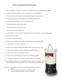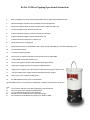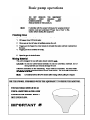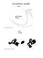
1
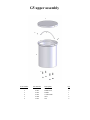
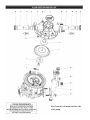
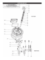
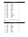
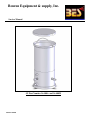
Benron Equipment & supply, Inc.
Service Manual
G5 Part Number 16-400A. and 16-400M
Edition 10/2008
Ez-Tex G5 Operational Instructions
1. Before attempting to use the G5 check material manufacturer for mixing and spraying instructions.
2. Check the G5 Hopper and make sure it is absolutely free from foreign debris.
3. Pull pressure regulator knob and turn counterclockwise all the way until a stop.
4. Selecttheproperspraytipforthefinishyouneedandinstallontothegun.
5. Closeairvalveontheguntostoptheairfromflowingout.
6. Connect material hose and air hose to the G5.
7. Connect material hose and air hose to gun.
8. Mix the material you’re working with.
9. Checkmaterialviscositywithfunnelsupplied,makesureitflowsasthickaspossiblewithoutlumps.
10. Pour material into hopper.
11. Cover the G5 with the lid supply.
12. Turn on your air compressor and make sure the pressure is not exceeding 100psi.
13. Connect airline to G5 air inlet connector. (A1)1
14.Turnpressureregulatorclockwiseuntilmaterialstartsflowinginthehose. (A2)
15. Trigger gun to purged air from hose spraying into a different bucket.
16. Open air valve to allow the material to atomize.
17.Sprayonatestsurfacemakingsureyouhavethedesiredsprayfinish.
18. Lock pressure regulator on your setting by pushing knob to secure setting.
19.Forcleaninggobacktostep#12andflushwithwater,whencleaninsert1blueball
into the hose run with water until hose is clean, if not clean repeat cleaning steps.
Note: A. Always practice with clean water before supplying any material to
the G5.
B. Alwaystestspraybeforeapplyingonthefinishsurface.
C. Never use material that dries in less than 30 minutes.
A2
A1
Ez-Tex G5 Micro Topping Operational Instructions
1.
Before attempting to use the G5 check material manufacturer for mixing and spraying instructions.
2.
Check the G5 Hopper and make sure it is absolutely free from foreign debris.
3.
Pull pressure regulator knob (A2) and turn counterclockwise all the way until a stop.
4.
Connect air regulator kit p/n 15-285 to air outlet (A4).
5.
Connect material line adapter p/n 15-281 to material hose p/n 10-220.
6.
Connect material hose adapter to the G5 material outlet (A3).
7.
Connect material hose and air hose to Coltcrete gun.
8.
Mix the material you’re working with.
9.
Check material viscosity we recommended to mix as paint viscosity, and making sure material is not draying to fast.
10.
Pour material into hopper.
11.
Cover the G5 with the lid supply.
12.
Turn on your air compressor and make sure the pressure is not exceeding 100psi.
13.
Connect airline to G5 air inlet connector (A1).
14.
Turnpressureregulatorclockwiseuntilmaterialstartsflowinginthehose.
15.
Trigger gun to purged air from hose spraying into a different bucket.
16.
Adjustpressureregulator(A2)toallowmaterialtoflowoutfromtheguntoadistanceof18”.
17.
Turn p/n 15-285 pressure regulator clockwise until material pressure at 50psi.
18.
Make a spray test on a deferent working surface.
19.
Forfinaladjustmentusethegunairormaterialknob.
20.Whenfinishmakesuretocleanthesprayerimmediatelytoeliminatematerialtodryinthesprayer.
Note:
A.
B.
C.
D.
E.
Always practice with clean water before supplying any material to the G5.
Alwaystestspraybeforeapplyingonthefinishsurface.
Never use material that dries in less than 30 minutes.
Material must be strained before use to avoid clogs in the gun.
We recommend to use the Benron air compressor p/n 18-550 or 18-600
A2
A4
A3
A1
Basic pump operations
Gun and Hose assembly
Gun assembly P/N 16-311
Hose assembly P/N 13-060/G5
P/N 16-311 Gun assembly
Item
1
2
3
4
5
6
7
8
9
10
11
17
13
14
15
16
18
19
Part Number
16-107
16-103
16-105
16-106
16-108
16-300
16-301
10-116
16-302
10-228
16-303
10-110
10-122
10-108
10-113
16-114
10-123
10-304
Description
Retaining Ring
Tip 3/16"
Tip 1/4"
Tip 5/16
Gun Body
Nut Guid
Gun Needle Assy
"O"-Ring
Fluid Control Assy
Needle Fitting Includes "O"-Ring
Air Fitting
Air valve
Sefty Clip Trigger
Gun Trigger
E-Ring
Trigger Pin
Air Fitting
Fluid Fitting
Qty
1
1
1
1
1
1
1
4
1
1
1
1
1
1
2
1
1
1
G5 lower assembly
Note:
When install pump must add clear
silicon gasket to surface.
Air hoses plumbing:
A to A 3/8” air hose
B to B 1/4” air hose
C to C 1/4” air hose
1
2
C
5
4
3
B
8
7
6
8
C
9
14
10
11
11
12
13
15
16
8
A
17
15
A
13
18
B
19
Item Number
1
2
3
4
5
6
7
8
9
10
11
12
13
14
15
16
17
18
19
Part Number
13-056
16-013T
10-304
16-413
16-403
13-067T
N/A
16-066T
16-411
16-402
19-157
16-406T
N/A
13-068
18-108
13-073
16-405T
10-123
16-410
Description
1/2” Pump
Pump Tee air fitting
1” x 3/4” fluid fitting quick connect
3/4” x 4-1/2” Material tube
1/2” x 3/4” adapter
Mini regulator
Mini regulator mounting nut
1/4” x 1/4” air fitting
Push retainer for stud
Tank base
1/4” Tee
3/8” Air fitting
Nut and washer for 18-108
Safety air valve
Bulkhead Connector
Air fitting
3/8” air fitting
1/4” Air fitting
5/16”-18 x 5/8” bolt
Qty
1
1
1
1
1
1
1
3
4
1
2
1
2
1
2
1
1
1
4
G5 upper assembly
1
3
2
2
4
5
6
Item Number
1
2
3
4
5
6
Part Number
N/A
16-412
16-407
16-401
16-409
12-210
Description
Lid
Handle lock
Handle
5 Gallon tank
Stud
Nut
Qty
1
2
1
1
4
4
Note: Item #61 will mount on other side
of the pump.
AIR SECTION PARTS LIST
Item
Part Number
101
102
103
104
111
118
119
120
122
129
130
131
132
133
134
135
136
137
138
139
140
141
142
143
12-048
12-029*
12-028
12-041
12-036
12-047
12-046*
12-045
12-042*
12-026
12-027*
12-049
12-030*
12-033
12-034
12-035
12-039
12-038*
12-037*
12-040*
12-032*
12-031*
12-044
12-043
Note:
12-051
Description
Motor Body
"O" Ring
Sleeve
Snap Ring
Spool
Pilot Rod
"O" Ring
Spacer
Snap Ring
Muffler Assembly
Gasket
Bolt
Gasket
Washer
Bolt
Valve Block
Plug
"O" Ring
Packing "U" Cup
Packing "U" Cup
Valve Insert
Valve Plate
Washer
Plate
Qty
1
2
1
2
1
1
4
3
2
1
1
8
1
4
4
1
1
1
1
1
1
1
2
2
Air Motor Repair Kit ( Includes All Parts Marked With * )
FLUID SECTION PARTS LIST
Item
1
2
5
6
7
15
19
21
26
41
42
61
62
63
124
Part Number
12-006
12-004
12-005
12-008
12-007
12-009
12-016
12-019
12-049
12-017
12-018
12-015
12-010
12-012
12-049
Description
Qty
Rod
"O" Ring
Washer
Diaphragm Nut
Diaphragm
Fluid Cap
"O" Ring
Insert
Bolt
Sleeve
Duckbill
Manifold
Flange Nut
Plug
Stud
1
1
2
2
2
2
4
4
8
4
4
2
24
6
8
Rotortex Warranty
G5 Warranty
All products manufactured by Benron Equipment & Supply, Inc. are warranted to the original purchaser against defects in
material and workmanship at the time of sale by an authorized Benron Equipment & Supply distributor and for a period of 12
months from date of purchase. This warranty applies only if the product is operated and maintained in accordance with Benron’s
written instructions.
Benron will repair or replace any part of the equipment proven defective. Repair or replacement under this warranty shall be the
purchaser’s sole remedy for breach of this warranty. Benron Equipment and Supply will not be responsible for any downtime
resulting from breakdown or for cost of rental equipment while repairs are being made.
This warranty does not cover damage to the product resulting from improper use, accident, user’s negligence, or if the product has
not been operated or installed in accordance with Benron’s recommendations. This warranty does not cover damages caused by
service or repair performed by other than a Benron authorized repair center. Benron is not liable for incidental or consequential
damages or to damages to other properties caused by use of the product in a faulty condition or manner.
Any implied warranty of merchantability or fitness for a particular purpose is limited to 90 days for professional rental use, and
for One year (12 months) for professional contractor use, from date of purchase. Some states do not allow limitations on how
long implied warranty lasts so above limitations may not apply to you.
If product is defective in material or workmanship during the warranty period, return it with proof of purchase to Benron
Equipment & Supply, Inc. or to Benron authorized warranty service center, for verification of claimed defect. If the alleged
defect is verified, Benron will repair or replace (at Benron’s option) any defective parts, and will return the product, transportation
prepaid. If no defects in material or workmanship are found, Benron will repair the product at a reasonable charge. Charges may
include the cost of parts, labor, and freight.
One year limited warranty, excluding consumable components.
Two
The items, which are not covered, are:
Guns packing
kit, ball valves, Material hose, Air hose and control cords.
Spray tips, Gun needle, Rotor
and Stator,
This warranty does not cover damage or defects caused by or related to Abrasion, Corrosion, Abuse, Misuse, Negligence,
Accident, Normal wear, Faulty Installation or tampering in manner which impairs normal operation.
All warrantee clime on the Honda engine will process by only Honda authorize repair center only
with prove of purchase of the original receipt.
Benron equipment & Supply, Inc.
15823 Stagg Street Van Nuys, CA 91406
In USA Call: 1 (888) EASY-TEX (888 327-9839)
In California Call: (818) 787-4455
Fax: (818) 787-8866