1
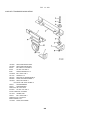
TM 5-3805-254-14&P-1
TECHNICAL MANUAL
OPERATOR'S, ORGANIZATIONAL, DIRECT SUPPORT,
GENERAL SUPPORT AND DEPOT MAINTENANCE MANUAL
(INCLUDING REPAIR PARTS INFORMATION AND
SUPPLEMENTAL MAINTENANCE INSTRUCTIONS)
FOR
TRUCK, DUMP, 20 TON, 6X4,
ON-OFF HIGHWAY 71,000 GVW,
IHC MODEL F-5070 (CCE)
(NSN 3805-00-192-7249)
HEADQUARTERS, DEPARTMENT OF THE ARMY
AUGUST 1980
This publication contains copyright material.
TM 5-3805-254-14&P-1
TECHNICAL MANUAL
No. 5-3805-254-14&P-1
}
HEADQUARTERS
DEPARTMENT OF THE ARMY
WASHINGTON, DC, 22 August 1980
OPERATOR'S, ORGANIZATIONAL, DIRECT SUPPORT,
GENERAL SUPPORT AND DEPOT MAINTENANCE MANUAL
(INCLUDING REPAIR PARTS INFORMATION AND SUPPLEMENTAL
MAINTENANCE INSTRUCTIONS)
FOR
TRUCK, DUMP, 20 TON, 6X4, ON-OFF HIGHWAY
71,000 GVW, IHC MODEL F-5070 (CCE)
(NSN 3805-00-192-7249)
REPORTING OF ERRORS
You can Improve this manual by recommending improvements using DA Form 2028 (Recommended
Changes to Publications and Blank Forms) or DA Form 2028-2 located In the back of this manual.
Mall the form direct to Commander, US Army Tank-Automotive Materiel Readiness Command, ATTN:
DRSTA-MBS, Warren, MI 48090. A reply will be furnished direct to you.
PART
ONE.
TWO.
THREE.
DUMP TRUCK OPERATOR'S MANUAL
SUPPLEMENTAL OPERATING, MAINTENANCE AND REPAIR PARTS INSTRUCTIONS
SPECIAL PARTS CATALOG
NOTE
Refer to TM 5-3805-254-14&P-2 for Special Service Manual.
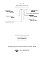
Credit Is hereby given to International Harvester Company for permission to reproduce the following manuals
procured under Contract No. DSA-700-72-C9235:
Operator's Manual No. 1086872-R1
Special Parts Catalog No. 1086677-R1
This technical manual Is an authentication of the manufacturer's commercial literature and does not
conform with the format and content specified in AR 310-3, Military Publications. This technical
manual does, however, contain available Information that Is essential to the operation and
maintenance of the equipment.
i/(ii blank)
PART ONE
OPERATOR'S MANUAL
INTERNATIONAL HARVESTER COMPANY
OPERATOR'S MANUAL
NO. 1086872-R 2
FOR
TRUCK, DUMP, 20 TON, ON/OFF HIGHWAY
(184 INCH WHEELBASE, MODEL F-5070)
PRODUCED FOR U.S. ARMY
ON CONTRACT NO. DSA-700-72-C-9235
INTERNATIONAL®
OPERATOR'S
MANUAL
1086872-R2 (REV. 1/76)
IMPORTANT
You were presented with an "Owners Service Policy" by
the dealership from whom you purchased your new
International vehicle.
Should the occasion arise where warranty service is
required it will be necessary that you present to the
servicing dealer this "Owners Service Policy" to verify
warranty qualification.
For this reason it is important that this policy be kept
with the vehicle at all times.
F - 5070 PAYSTAR
SERIES
Cont. DSA-700-72-C-9235
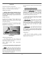
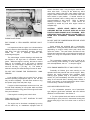
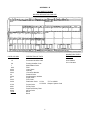
OPERATION - PREVENTATIVE MAINTENANCE AND LUBRICATION
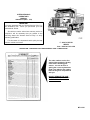
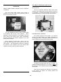
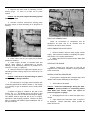
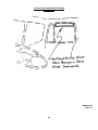
The code numbers on the line
setting ticket positively identify
units used in building your
vehicle. You can be sure of
getting the correct replacement
parts if you take the line setting
ticket in the glove compartment
with you.
DO NOT REMOVE THE LINE
SETTING TICKET ATTACHED
TO THE VEHICLE.
MT-16757
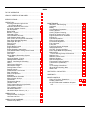
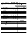
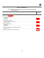
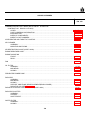
INDEX
TO THE OPERATOR ................................................. 1
VEHICLE CERTIFICATION LABEL.............................. 1
SPECIFICATIONS ...................................................... 2
OPERATION.............................................................. 3
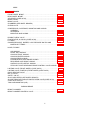
Air Gauge Indicator Light & Low
Air Pressure Buzzer ............................................ 9
Automatic Reservoir Drain Valve .......................... 12
Air Vents & Heater Controls .................................. 10
Ash Receptacle ...................................................... 8
Brake Pedal ........................................................ 11
Break-in - Engine ................................................... 3
Cigarette Lighter..................................................... 9
Circuit Breakers & Fuses ........................................ 9
Cold Weather Starting Aids ..................................... 7
Door Control & Lock (Inside & Outside).................... 5
Door Glass Window Regulator................................. 5
Differential "No Spin" ........................................... 50
Driving Truck........................................................ 13
Dump Body .......................................................... 45
Engine Brake Control ........................................... 10
Engine Shutdown................................................... 7
Engine Operating Instructions ............................... 32
Front Wheel Brake Limiting Valve Control ............. 12
Fuel Gauge ........................................................... 9
Fuel Tank .............................................................. 9
Gauge Battery Generating System
Indicator.............................................................. 8
Governed Speed - Engine..................................... 15
Headlight Beam Selector ........................................ 8
Heating, Ventilating & Defrosting ........................... 10
Hood ................................................................... 16
Light Control Switches ............................................ 8
Oil Pressure Gauge ................................................ 8
Parking Brake Control .......................................... 12
Parking Vehicle .................................................... 16
Power Divider Lock Control .................................. 11
Rear View Mirror ................................................. 13
Seat Air Suspension............................................. 31
Seat Belts ............................................................. 5
Speedometer & Odometer ..................................... 7
Staring Switch & Keys ........................................... 6
Tacbometer............................................................ 8
Temperature Gauge ............................................... 7
Throttle Control ..................................................... 9
Traffic Hazard Warning Light Switch...................... 13
Transmission Controls .......................................... 15
Turn Indicator Control .......................................... 13
Windshield Washers ............................................... 9
Windshield Wiper Control .( Air ).............................. 9
LUBRICATION ........................................................ 27
Oil Specification for Engine .................................. 17
Lubricant and Fuel ............................................... 40
LUBRICATION DIAGRAMS ...................................... 26
Chassis Dump Body ............................................ 46
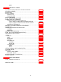
MAINTENANCE........................................................ 16
Alternator, Self-Rectifying...................................... 19
Antifreeze ............................................................ 19
Battery................................................................. 25
Cold Weather Preparation..................................... 20
Cooling System.................................................... 19
Cooling System Cleaning...................................... 19
Engine Air Cleaner (Dry Type)............................... 17
Engine Maintenance: Schedule............................. 42
Engine Oil............................................................ 17
Fan Belt Adjustment ............................................. 18
Filling Cooling System .......................................... 19
Front Wheel Alignment ......................................... 24
Fuel, Lubricant ..................................................... 40
Fuel Filter............................................................. 17
Fuel Pump Screen & Magnet ................................ 17
Headlight Removal ............................................... 23
Oil Filter - Engine (Auxiliary).................................. 17
Paint, Bright Metal and Upholstery
Maintenance ........................................................ 16
Power Steering Pump Oil Reservoir.................... 18
Radiator Cap........................................................ 19
Radiator Coolant Level ......................................... 19
Radiator Shutters ................................................. 19
Seat Air Suspension............................................. 31
Thermostat (Cooling System)................................ 19
Transmission (Automatic)...................................... 20
Tires .................................................................... 23
Truck Storage Instructions .................................... 21
Wheel & Rim Mounting Nuts ................................. 25
Water Filter .......................................................... 20
UNIT REFILL CAPACITIES ....................................... 30
WARRANTY ............................................................. 52
MISCELLANEOUS
Lifting & Tie Down Illustrations ...................... 48 & 49
Loading Clearances.............................................. 47
No Spin Differential Installation & Operation........................................................... 50 & 51
A WORD TO OWNER AND OPERATOR
E very effort has been made to assure that your
new vehicle has been engineered and manufactured to
provide continued trouble-free service.
Materials
selected to manufacture the many parts which make up
the vehicle exhaustive test and research to make certain
that acceptable, safe service life is realized.
stop and go service, more frequent inspections should
be scheduled.
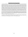
RUBBER PARTS: Rubber is subject to deterioration
wherever it is used. Brake cylinder parts, both air and
hydraulic, should be considered for periodic replacement
based upon the severity and length of service. Usually
careful inspection by experienced mechanics will
disclose the need for attention. Some parts, such as air
brake chamber diaphragm, should be inspected once a
year or every 50,000 miles and replaced if considered
unserviceable for further use.
There is, however, an area in which the vehicle
owner plays an important part and which determines in a
large measure the extent of continued, safe trouble-free
service to be realized from the owner's investment in the
vehicle. This has to do with the responsibility which
rests with the owner in seeing that the vehicle receives
proper care through following the periodic lubricating
procedures and arranging for regular inspection intervals
to assure that parts that normally deteriorate are
replaced or repaired. In addition, it would be good
practice to ask your IH dealer or Service Center to make
an inspection of the running gear of your vehicle at least
once a year. The lubrication intervals present a good
opportunity to inspect the vehicle, and we suggest that
the following points be checked at these intervals.
STEERING: Check tie-rod and drag-link and clamp
bolts. They must be tight. Ask your service mechanic to
examine the steering mechanism.
Minor adjustments could head off future problems.
WHEELS, RIMS, TIRES: Check condition of and tighten
wheel and rim mounting bolts and nuts.
Examine
condition of tires. Cut or broken tire casings should be
replaced. Keep tires inflated properly.
AXLES, BODY AND CHASSIS COMPONENTS: Check
to assure that axle mounting U-bolt nuts, body mounting
brackets and chassis components (attaching or
mounting bolts and nuts) are securely tightened.
A good general vehicle check by an experienced
serviceman will give you assurance that your vehicle is
still in a safe condition, ready to work for you.
ENGINE EXHAUST SYSTEM: Mufflers, exhaust pipes
etc. All joints tight. No leaks in the system.
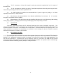
VEHICLE CERTIFICATION LABEL
A Vehicle Certification Label is affixed to all
vehicles in addition to the serial or warranty plate. This
label certifies that the vehicle conforms to all applicable
Federal Motor Vehicle Safety Standards in effect at the
date of manufacture. Do not remove or deface this
label. The label contains the Certified Gross Vehicle
Weight Rating (GVWR) and Gross Axle Weight Rating
(GAWR). The GVWR means the maximum design
weight of the vehicle including the vehicle itself and
everything that is loaded into or onto the single vehicle.
The GAWR is the maximum weight that any one axle
can carry. Note that the sum of the axle GAWR's may
be greater than the GVWR, so that it is not necessarily
proper to load both axles at the same time to the
maximum capacity shown for each. The maximum
GVWR should never be exceeded.
ELECTRICAL: Loose, weathered, cracked or broken
wires replaced to safeguard against breakdown on the
road or possible shorts.
PIPES, HOSES: Leakage, air, water or hydraulic lines.
Check pipes and hose routing. They should not be
pushed over against hot exhaust pipes or near the
exhaust. Replace cracked, weathered or deteriorated
hoses.
LINKAGES: Transmission and brake rods, clevis pins
and lock pins should be in good repair and secure.
Control linkages properly adjusted.
BRAKES AND BRAKE LININGS:
Brake linkages,
controls and the condition of brake linings should be part
of the periodic inspections.
The GAWR is the maximum weight measured at
the ground permissible on that axle system. These
ratings are developed on the basis of the minimum
component capability, be it axles, springs or tires.
Have your vehicle's brake system inspected at least
once each year. Where vehicles are used in severe
service or in considerable
1
For assistance in understanding your vehicle
weight
carrying
capability,
consult
your
local
International Harvester dealer or branch.
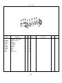
SPECIFICATIONS
ENGINE
Cylinders
Bore & Stroke
Piston Displacement (Cu. In.)
Horsepower
Firing Order
ELECTRICAL
Electrical System, 12 Volt
NTC-290
6
5-1/2 x 6 Inches
855
290 @ 2100 RPM
1-5-3-6-2-4
Negative Ground
TO THE OPERATOR
The purpose of this manual is to familiarize you
with the controls of your vehicle and to provide sufficient
information to enable you to perform minor routine
services necessary for continued efficient operation. To
protect your equipment, study this manual before you
start to operate the vehicle.
If you need major information not given in this
manual, or if you require services of a trained
serviceman, we urge you to use the extensive facilities
offered by IH dealers and branches in your locality. IH
dealers and branches keep abreast of the best methods
of servicing IH equipment, and have up-to-date facilities
for providing prompt, first-class service. They carry
ample stocks of essential International service parts.
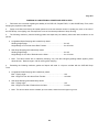
When you need parts, always give the unit code
number, vehicle model and chassis serial number, and
the serial number of the unit for which the parts are
required.
We suggest that you write these serial
numbers in the spaces provided so that you have them
at hand when parts are required. Request the salesman
to assist you in obtaining these serial numbers when the
vehicle is delivered to you.
NOTE: For Cummins Engines refer to their
Engine Operator's Manual for detailed Diesel Engine
information.
VEHICLE MODEL
CHASSIS SERIAL NUMBER
(Stamped on plate cab door inner panel, left
side.)
(Stamped on frame left side rail, front)
ENGINE SERIAL NUMBER
TRANSMISSION NUMBER
(Cummins engines stamped on plate, left side of
gear case, front of engine.)
(From specification cards.)
FRONT AXLE NUMBER
REAR AXLE NUMBER
(From specification card)
(From specification card.)
2
OPERATION
BREAK-IN DIESEL ENGINE (Except IH Diesel Engines)
The way you operate your new engine during the
first 100 hours' service will have an important effect on
the life of the engine and its parts. Its moving parts are
closely fitted for long service, and even though all diesel
engines are run on a dynamometer for several hours
before they leave the factory, an additional period may
be required before uniform oil films are established
between all mating parts.
During the first 100 hours' service:
1. Operate most of the time at one-half to threequarters throttle.
Do not operate at maximum
horsepower for more than five minutes at a time.
2. Do not idle the engine for long periods.
3. Keep a close watch on your instruments. Back
off on throttle if water temperature exceeds 190 degree
F.
4. Drive in a gear low enough so that you can
accelerate under any condition to prevent lugging your
engine. DO NOT LUG THE ENGINE AT ANY TIME.
"During this break-in period, avoid full throttle starts
and, if possible, abrupt stops. Gentle braking during the
first hundred miles of operation will result in longer brake
life and better future performance. Avoid hard stops
especially during the first 250 miles of operation, since
brake misuse during this period could sharply reduce
future brake efficiency."
3
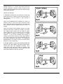
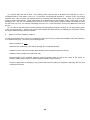
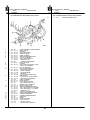
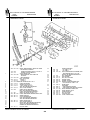
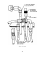
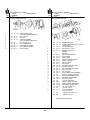
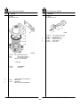
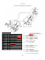
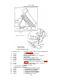
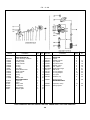
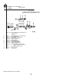
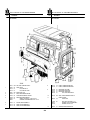
OPERATION
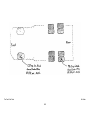
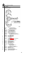
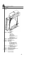
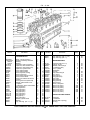
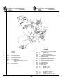
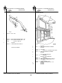
1.
2.
3.
4.
5.
6.
7.
8.
9.
10.
11.
12.
13.
14.
15.
16.
17.
18.
19.
20.
21.
22.
Door Control
Turn Indicator Control
Power Divider Lock Control
Exhaust Brake Switch
Glow Plug Switch
Oil-Water Temperature Indicator Light
Glow Plug Indicator Light
Battery-Generating System Indicator Gauge
Water Temperature Gauge
Left Turn Indicator Light
Oil Pressure Gauge, Engine
Headlight High Beam Indicator Light
Air Pressure Gauge
Right Turn Indicator Light
Fuel Level Gauge
Low Air Pressure Light
Parking Brake Control
Dome and Panel Lights
Headlights
Fuel Pressure Gauge
Ash Receptacle
Transmission Oil Pressure Gauge
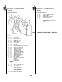
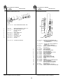
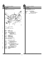
23.
24.
25.
26.
27.
28.
29.
30.
31.
32.
33.
34.
35.
36.
37.
38.
39.
40.
41.
42.
43.
44.
4
Transmission Oil Pressure Indicator Light
Transmission Oil Temperature Gauge
Transmission Oil Temperature Indicator Light
Air Cleaner Restriction Gauge
Cigarette Lighter
Circuit Breaker Switch-Start-Run
Dump Body Control
Automatic Transmission Control
Auxiliary Transmission Control
Starting Switch Key
Starting Button
Throttle Control
Emergency Brake Release
Accelerator Pedal
Speedometer and Odometer
Brake Pedal
Front Wheel Brake Limiting Valve
Headlight Beam Selector
Power Take Off Control
Fuel Primer Pump
Window Regulator
Tachometer (Behind Turn Signal Control)
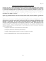
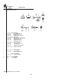
OPERATION
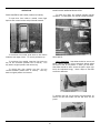
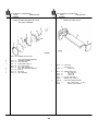
DOOR GLASS WINDOW REGULATOR
DOOR CONTROL AND LOCK (Inside and Outside)
To lower door glass, turn window regulator handle
clockwise. To raise glass, turn handle counterclockwise.
To open door from inside or outside, insert finger
tips into door control recess and pull handle outward.
To lock door from inside, push down on lock button
located at rear edge of door. To unlock, pull button up.
SEAT BELTS
To lock door from outside, insert key into lock; turn
key 1/4 turn clockwise (towards rear of vehicle). Turn
key back to original position and remove key.
Use of Seat Belts. Seat belts should be worn at all
times. Before fastening a front seat belt, always adjust
the driver's seat to the position in which you will drive.
Seat belts should be worn across the pelvic region (hip
bone) and adjusted snugly. Never adjust a seat belt
across the abdomen.
To unlock door from outside, turn key 1/4 turn
counter-clockwise (toward front of vehicle). Turn key
back to original position and remove.
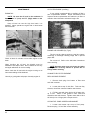
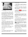
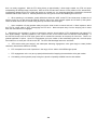
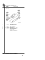
To lengthen the belt, tip the buckle end downward, as
shown, and pull the buckle until the belt ends can be
joined.
5
STARTING SWITCH AND KEYS
OPERATION
Turning key to the RIGHT, then pushing in the
starting button (transmission in neutral) STARTS THE
ENGINE. Leaving it turned to the RIGHT leaves the fuel
shut off valve and all electrical units "ON".
Insert tongue into open end of buckle and snap
together. The belt can be shortened after it is connected
by pulling on the loose end until the belt is snug and
comfortable. Push in on the button release latch to
remove the seat belt.
When adjusting shoulder belt, for proper slack, place
fist on chest under strap. Shoulder belt should not be
tight across body.
With the key turned to the LEFT, all electrical units
controlled by the switch are "ON" (except the diesel
engine fuel shut off valve)
Buckle shoulder belt in same manner as regular seat
belt.
ENGINE STARTING: Cummins Diesel Engine
Always pull the belt completely out of the retractor
before adjusting and fastening the other half of the belt
unit.
1. Set the parking brake control.
2. Place the transmission control in the neutral
position.
Care of Seat Belts. Seat belts should receive the
same care as the finest fabric.
3. Pull out the throttle control or depress the
accelerator sufficiently to "crack" the throttle; the engine
will then run at "fast idle" speed. The throttle control
should be gradually pushed in until the proper idling
speed is obtained.
Clean with mild soap; do not use cleaning solvents
or abrasives.
CAUTION: Do not bleach or re-dye color of
webbing as same may cause a severe loss of tensile
strength.
4. Pull out the compression release control (If so
equipped.)
Keep belts flat to avoid twisting and roping when not
being used. Do not place heavy or sharp objects on
belts.
5. Turn starting switch key to right and push in on
starting button. Release starting button the instant the
engine starts.
The entire seat belt assembly should be inspected
periodically for corrosion, wear, fraying or weak spots.
The seat belt mounting bolts should be tight at all times.
Any seat belt severely strained in an accident should be
replaced immediately. All belts should be replaced at
least every five years.
NOTE: To avoid possible damage to the starting
mechanism, release the starting button as soon as
the engine starts. Never push starting button while
the engine is running. If the engine does not start
promptly, DO NOT OVERTAX THE STARTING
MOTOR OR THE BATTERY. Do not use the starting
motor longer than 30 seconds at a time.
CAUTION: Shoulder belt should never be worn
without regular lap seat belt.
Wait at least 15 seconds between attempts to start
the engine to prevent heat (generated in the starting
motor) from scorching the starting motor commutator.
NOTE: A manual override switch is provided on
the forward end of the electric fuel shut-off
6
valve above the fuel pump. In case the electric fuel
shut-off valve is inoperative, turn switch to the right to
open the fuel shut-off valve.
6. After engine starts, pump primer slowly to keep
engine idling smoothly. In cold weather this may require
4 to 5 minutes, or longer. Do not accelerate engine.
6. After three or four seconds of cranking push in
the compression release control (if so equipped) and
continue to crank until the engine starts. Release
starting button the instant the engine starts.
7. After engine has warmed up until it does not
falter between primer strokes, stop pumping. Close
primer and lock. Turn off glow plug switch. (Red
indicator light will go off.)
NOTE: Do not run the starting motor for more
than approximately 30 seconds at any time. If the
engine fails to start or makes a false start, do not
turn the starting switch key again until the engine
has come to a complete stop.
DO NOT USE PREHEATER WHEN TRUCK IS IN
MOTION. THE PREHEATER BURNS INCOMING AIR,
AND MAY RESULT IN DAMAGE TO THE ENGINE.
CAUTION: Do not start or run an engine in a
closed garage.
Exhaust gas from all internal
combustion engines' contains poisonous carbon
monoxide gas which is odorless, tasteless, and
colorless. Keep the garage doors wide open when
starting and keep your cab completely ventilated at
all times to avoid drowsiness.
A basic rule of good engine operation concerns the
importance of idling the engine from three to five minutes
before shutting down. This few minutes idling allows the
lubricating oil and water to carry heat away from the iron
masses.
ENGINE SHUTDOWN
The larger the engine, the greater the need for this
idling period and of course, the length of the idling period
should somewhat follow the size of the engine in order to
avoid seals or like features of an engine being damaged
by rising heat.
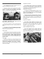
COLD WEATHER STARTING AIDS
As an aid in starting the engine in cold weather
temperatures, an intake air preheater arrangement may
be used.
Cummins Diesel Engine:
To stop the engine turn the starting switch to "OFF".
The preheater equipment consists of a hand priming
pump to pump fuel into the intake manifold, a glow plug
electrically heated by the battery, and a switch to turn on
the glow plug when fuel is pumped into the intake air.
Pulling the control out will stop the engine. If the
engine has been stopped by pulling the control, the
shutdown latch assembly located at inlet side of engine
blower must be reset before engine can be started.
CAUTION: Do not use ether in conjunction with
the preheater.
CAUTION: If engine has had to be stopped using the
emergency shut-down, the cause should be found
before the engine is started again.
To use the preheater for cold starting follow this
starting procedure:
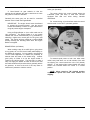
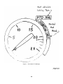
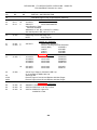
TEMPERATURE GAUGE
1. Disengage clutch.
The temperature gauge indicates the temperature of
the coolant in the cooling system.
2. Do not accelerate engine during the starting
procedure.
The gauge operates only when the starting switch is
turned to "ON" position, or is turned to the left to operate
the accessories. If the indicator suddenly rises to the
240 degree position, the engine should be stopped and
the cause of overheating determined.
3. Push glow plug switch located to the left of the
operator to "ON" position. Red indicator light must be
on.
SPEEDOMETER AND ODOMETER
The speedometer indicates the vehicle speed in
miles (or kilometers, if so adapted) per hour. The
odometer records the total number of miles traveled.
The units operate through a flexible cable from the
transmission.
4. After red light has been on for 20 seconds, start
cranking the engine. As soon as engine begins rotating,
operate the preheater priming pump to maintain 40 to 60
psi fuel pressure.
Use of primer located at the
instrument panel lower left side before the 20 second
interval will wet glow plug and prevent heating.
5. If engine does not start within 20 seconds, stop
cranking.
Wait 30 seconds and repeat cranking
operation.
7
records the number of hours the engine has operated.
The hour meter is based upon an average of 100,000
revolutions per hour.
Keep your eye on the tachometer and observe
engine speed to avoid "overspeeding" and "lugging" the
engine.
OIL PRESSURE GAUGE - ENGINE
The engine oil pressure gauge indicates the amount
of oil pressure being delivered to the engine. At engine
idle speed, the oil pressure should be approximately 1530 pounds; at normal operation speeds, 30-70 pounds.
If gauge fluctuates or does not register when the
engine is operating, stop the engine immediately and
correct cause.
For cruising on level highways, operate the engine
at approximately 85 per cent of governed speed or about
three-quarters throttle.
Where you advance to full throttle and the engine
cannot reach governed R.P.M., the engine is lugging.
To avoid lugging the engine, select gears which will
permit your engine to reach governed R.P.M. when you
advance to full throttle.
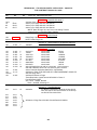
ASH RECEPTACLE
GAUGE,
BATTERY
INDICATOR
GENERATING
SYSTEM
The ash receptacle is located on top and in the
center of the instrument panel and is convenient to both
the operator and passenger.
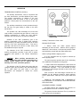
The battery, generating system indicator gauge
indicates the condition of the battery, alternator and the
voltage regulator.
LIGHT CONTROL SWITCHES
The gauge is divided into two sections, one marked
BATT (battery); the other marked GEN (generating
system).
The light control switches are located to the left and
right of the steering wheel at the top of the instrument
panel and are marked respectively.
With starting switch on, before starting engine the
gauge will show the condition of the battery. The battery
section of the gauge is subdivided into three colored
segments.
HEADLIGHT BEAM SELECTOR
The foot-operated beam selector, convenient to the
driver's left foot, is used to control the upper and lower
headlight beams. Use of the beam selector permits the
driver to lower the headlight beam when approaching or
passing vehicles, and to raise the headlight beam for
open highway use or whenever necessary. A red light
(on the instrument panel) glows when the headlights are
on "upper" beam.
GREEN a well-charged battery
YELLOW a low battery charge
RED a very low battery charge
With the engine running at operating speeds, the
gauge will show the condition of the generating system.
The generating section of the gauge is divided into two
colored segments:
GREEN generating system working properly.
RED voltage output too high.
Constant reading in either RED area indicates that a
complete check of the battery and generating system be
made.
Range given is from 2000 to 2600 engine r.p.m. for
operation to 10,000 ft. altitude.
TACHOMETER
The tachometer (combined with the tachograph)
indicates the engine speed in revolutions per minute and
8
WINDSHIELD WIPER CONTROL (Air)
CIGARETTE LIGHTER
The windshield wiper motor is located at the top
edge of the windshield on left side of cab.
The cigarette lighter is located on the instrument
panel to the right of the operator. Push the lighter knob
in all the way. The lighter will automatically return to the
normal position when it is ready for use.
WINDSHIELD WASHERS
Turning the control to the left starts the air wipers.
The speed of the air wipers is regulated by rotating the
control. To position the wiper blades in the "park"
position, turn the control to the extreme right.
To operate the windshield washers, press in on the
button located at the top edge of the windshield to spray
solution on the windshield. Then, turn on the windshield
wipers to clean the windshield.
Keep the fluid reservoir filled with water at all times.
I.H. windshield washer solvent added to water will aid in
cutting road film and grease on the windshield and,
during cold weather, will prevent freezing of the water in
the container.
THROTTLE CONTROL
AIR GAUGE, INDICATOR LIGHT AND LOW AIR
PRESSURE BUZZER (Air Brakes)
The throttle control located to the right of the
operator and at the lower edge of the instrument panel
may be used to open the throttle slightly when starting
the engine, or to set the throttle at any position to
maintain a constant engine speed.
Should the air pressure in the air brake system fall
below approximately 60 pounds, a warning buzzer will
sound.
CIRCUIT BREAKERS AND FUSES
The warning buzzer will automatically shut off when
the air pressure in the system is sufficient (approximately
60 pounds) to operate the vehicle.
The various electrical units on these chassis are
protected by individual circuit breakers and fuses
conveniently located behind panel in approximately the
center of the Instrument Panel.
FUEL GAUGE
The fuel gauge is electrically operated and indicates
the level of the fuel in the tank. The gauge registers only
when the starting switch is "ON" or the key is turned to
the "accessory" position. NOTE: Gauge pointer may
not necessarily return to lowest reading when key is
turned to "OFF".
FUEL TANK
As fuel is consumed, air is drawn through the vent
into the fuel tank. Under certain climatic conditions, with
a quick drop in temperature and the vehicle inoperative,
moisture may accumulate in the fuel tank. Therefore,
keep the fuel tank filled, as much as practical, to avoid
moisture accumulation.
9
OPERATION
HEATING, VENTILATING AND DEFROSTING
Defrost
CAUTION: To clear the system of humid air,
operate blowers for 30 seconds at "Hi" speed before
moving "AIR OUTLETS" lever to "DEF".
HEATING To use as a fresh air heater, move "AIR"
inlet control lever to "FRESH". Adjust temperature
"HTR" (HEAT) lever as required to give the desired
degree of heat. Full right "HOT" position provides
maximum heat. Move "AIR OUTLETS" control lever as
desired to control air flow. For MAXIMUM AIR FLOW,
move both "FAN" switches to "HI". Switches can be
operated in any speed combination.
This will minimize rapid fogging of the glass, which
can occur if humid air is blown onto a cool windshield.
To improve defroster efficiency, remove ice and/or
snow from glass area.
FRESH AIR VENTILATION To permit fresh air to
enter directly into the cab, push in air door control (left
ventilator).
To direct fresh air through the heater for distribution
through the cab air outlets, place the control panel
"HTR" lever in the "OFF" position. Move the "AIR" lever
to "FRESH". Move "AIR OUTLETS" lever to direct air
stream as desired.
Adjust blower speed and air
registers for desired air flow. Blowers may be operated
individually or simultaneously in any available speed
combination.
Fresh Air Heat
To use as a recirculating type heater, operate heater
controls in normal manner and move "AIR" inlet control
lever to "RECIRC".
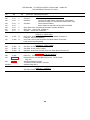
ENGINE BRAKE CONTROL OPERATION
Recirculating Heat
After the engine has reached normal operating
temperature and before starting a trip, position the
manual control switch on the instrument panel to "ON."
To obtain maximum defrosting, move "HTR" lever to
"HOT". Place "AIR OUTLETS" lever at "DEF" and "AIR"
lever to "FRESH". Adjust blower speeds to provide
desired air flow.
When the vehicle is in motion, the engine brake
control is in operation when the operator's foot is
removed from the accelerator pedal.
DEFROSTING
The engine brake may be used in general whenever
decelerating the vehicle is required, such as, descending
grades, city traffic or approaching traffic lights.
To put all air on windshield, move "AIR OUTLETS"
control lever to "DEF", close floor outlet.
10
OPERATION
POWER DIVIDER LOCK CONTROL (For Tandem Drive
Axles) (Air Operated)
A "rule-of-thumb" for gear selection is that the
operator should estimate the gear he would use to climb
the grade he is about to descend.
The power divider lock control located below the
instrument panel (left side) is used with vehicles
equipped with dual rear axles having interaxle
differentials.
Generally this same gear can be used for controlled
descent of the hill with the Engine Brake.
For normal driving on hard surface roads the control
should remain in the "OUT" (unlocked) position.
IMPORTANT: The engine should never be allowed
to exceed the governed speed. Use the service
brakes intermittently or shift to a higher transmission
range to prevent engine overspeed.
Using an Engine Brake on ice or slick roads can be
very successful. The Engine Brake is a very gentle
retarder and can be used effectively on icy pavement by
selecting a higher than normal gear for the given road
speed. The engine will then operate at a reduced RPM
thereby reducing the retarding effect when the Engine
Brake is energized.
BRAKE PEDAL (Air Brakes)
When making a stop for a traffic light or going down
a long grade, do not "fan" the air brake pedal rapidly as
this wastes air pressure. On long grades, use snubbing
"on-off" brake application to reduce the possibility of
extreme heat and wear to the brake lining. Another
good policy to follow is to let the engine assist in
reducing the vehicle speed. The best way to make a
stop is to apply the brakes as hard at first as the road
and load conditions will permit and then gradually reduce
the pressure, so that at the end of the stop there is
sufficient air pressure to hold the vehicle.
To transmit equal power to both rear axles when
under heavy load when one or both wheels of the axle
are slipping, the control should be in the "IN" (locked)
position. A red warning light located beside the power
divider lock indicates when the control is in locked
position.
NOTE: Move control to "IN" (locked) position
only at low speed and never when wheels are
slipping.
11
AUTOMATIC RESERVOIR DRAIN VALVE
OPERATION
DESCRIPTION
FRONT WHEEL BRAKE LIMITING VALVE CONTROL
(Air Brakes)
The DV-2 Automatic Reservoir Drain Valve ejects
moisture and contaminants from the reservoir in which it
is connected. It operates automatically and requires no
manual assistance or control lines from other sources.
The front wheel brake limiting valve control is
mounted on the lower edge of the instrument panel to
the left of the steering column.
The valve enables the driver to set his brake power
in accordance with varying road conditions.
When
operating a vehicle unloaded or over slippery roads, the
driver pulls out the limiting valve, which automatically
limits the maximum air pressure admitted to the front
wheel brake chambers.
PARKING BRAKE CONTROL
The primary purpose of this brake is to hold the
vehicle in a parked position or to assist in bringing it to
an emergency stop. The parking brake should not be
used to brake the vehicle during normal driving.
When operating a vehicle with a load or over dry
roads, the driver pushes the valve control into the dry
road position. This automatically allows the maximum
air pressure to be supplied to the front wheel brake
chambers as well as the rear brake chambers.
To apply the parking brake pull out on control. To
release the parking brake push in on control. NOTE: DO
NOT APPLY FOOT BRAKE WHILE PARKING BRAKE
IS APPLIED.
Upon loss of air pressure or reduction of air pressure
in the vehicle air system, the parking brakes will
automatically apply,
12
"blink" on and off when the turn indicator is operating.
OPERATION
TRAFFIC HAZARD WARNING LIGHT SWITCH
thereby providing an effective emergency brake.
If the chassis is equipped with a protected reservoir the
parking brake will not automatically apply.
The parking brake cylinder differ from the service brake
cylinders in that the parking brake cylinder apply the
brakes by spring pressure and release them by air
pressure where as the service brake cylinders apply the
brakes with air pressure and release them by spring
pressure.
The parking brake unit requires approximately 60
pounds air pressure before brakes can be released.
Manual Release
In event of air failure on the road or for towing the
vehicle, the spring brake can be released by removing
breather cap and backing off (counterclockwise) the
release bolt approximately 1-3/4" until brake shoes are
free from brake drums.
The traffic hazard warning light switch is required in
several states to flash both front and rear directional
signals simultaneously, thus warning oncoming traffic of
an emergency. The switch is located on the left side of
the steering column.
IMPORTANT: Before releasing spring brakes, be sure
vehicle is properly blocked so that when brakes are
released vehicle cannot move.
With the turn signal lever in center position, pull switch
out to operate signal lights. To turn off, move turn
indicator control to either right or left turn position, then
move back to center position. With switch pulled out,
both turn indicator lights on the instrument panel flash,
indicating operation of both front and rear directional
signal lights. Hazard warning operation is indicated by
simultaneous flashing of both turn signal indicators.
Hazard warning system should be used for emergency
only in compliance with the laws of the state in which the
vehicle is registered.
To Reset Brakes
REAR VIEW MIRROR
The rear view mirror contributes to safe operation of
the vehicle and can be adjusted to the position desired
by the operator.
1. Charge brake system with 60 pounds air
pressure.
DRIVING THE VEHICLE (Automatic Transmission)
2. Turn release bolt clockwise
(Approximately 50 ft. lbs. torque.)
Operation of the automatic transmission is controlled
by a selector lever mounted on the cab floor (Console).
The position of the lever is clearly shown by a range
indicator. When the instrument panel lights are turned
on the quadrant is illuminated.
until
tight.
3. Install breather cap with stainless steel screen
facing down.
TURN INDICATOR CONTROL
The turn indicator control is located on the
steering column below the steering wheel. To signal for
a right turn, push the control away from you. For a left
turn, pull the control toward you. Signal lights on the
front and rear of the truck and on the instrument panel
13
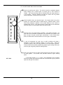
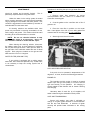
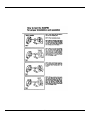
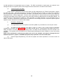
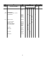
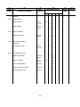
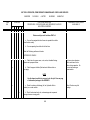
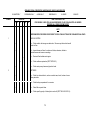
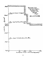
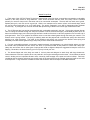
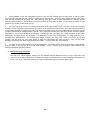
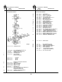
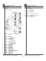
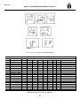
HT-750 CRD RANGE SELECTOR POSITIONS
Use this for backing the vehicle. The vehicle should be completely stopped
before shifting from a forward gear to reverse gear or from reverse to
forward. The reverse warning signal is activated when the range selector is
in this position. Reverse operation provides the vehicle with its greatest
tractive advantage. Reverse has only one gear.
Use this position when you start the engine. If the engine starts in any other
position, the neutral start switch is malfunctioning. Neutral position is also
used during stationary operation of the power takeoff (if your vehicle is
equipped with a PTO). Use neutral when the vehicle will be left unattended
while the engine is running-always apply the parking brake.
Use this one for all normal driving conditions. The vehicle will start in 1st
gear and as the accelerator is depressed, the transmission will upshift to 2nd
gear, 3rd gear, 4th gear, and 5th gear, automatically. As the vehicle slows
down, the transmission will downshift to the correct gear, automatically.
3, and 2) Occasionally, the road, load, or traffic conditions will make it
desirable to restrict the automatic shifting to a lower range. When the
conditions improve, return the range selector to the normal driving position.
These positions also provide progressively greater engine braking power (the
lower the gear range the greater the braking effect).
This is low gear-use this one when pulling through mud and snow or driving
up steep grades. This position also provides maximum engine braking
power.
MT 17878
In the lower ranges (1, 2, 3, and 4), the transmission will not upshift
above the highest gear selected unless the recommended engine governed
speed for that gear is exceeded.
14
OPERATION
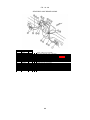
TRANSMISSION CONTROL (Auxiliary)
The auxiliary transmission, used in conjunction with
the main transmission, provides additional gear ratios.
The auxiliary transmission (in addition to the main
transmission) must be placed in one of the driving
positions / before power can be transferred to the rear
wheels.
The auxiliary transmission control protrudes through
the cab floor and gear shifting is similar to the main
transmission.
The operator can, after knowledge of his load and
road condition, manipulate the gear ratios of a main and
auxiliary transmission to obtain the most efficient
operation and road speed for his particular operation.
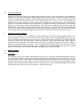
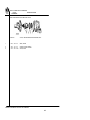
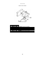
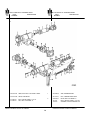
AUXILIARY TRANSMISSION
CODE 13538
Selection of the "UD" (underdrive) gear in the
auxiliary transmission gives a greater gear reduction
than provided by the main transmission and can be used
with any of the main transmission ratios. This ratio is
generally used where the vehicle is under heavy load
and additional torque is required.
Auxiliary Transmission Code 13538
DRIVING THE TRUCK
1. Always check the brake system before
attempting to drive the truck. Observe the air gauge to
determine if the minimum of 60 pounds pressure exists
and familiarize yourself with the brake pedal action.
The selection of the "OD" (overdrive) gear in the
auxiliary transmission provides a gear ratio to permit
increased road speeds in the various transmission
ratios.
Warm Up Engine Before Applying Load
It is very important that any engine be warmed up
before applying load.
CAUTION: When auxiliary transmissions are
used in combination with automatic transmissions a
loaded vehicle should not be started with the
auxiliary in the "OD" (overdrive) position.
The warm-up period provides time for the lubricating
oil to establish a film between moving parts.
In colder areas where temperature is often below 32
degrees F, the warm-up period for turbocharged engine
is especially important. The cold external oil lines
leading to the turbocharger will tend to slow oil flow until
the oil warms up.
The selection of the "D" (direct drive) gear does not
change the gear ratio provided by the main transmission
but is used where the gear ratios in the main
transmission are adequate to handle the vehicle
operation.
Slow oil flow to the turbo-charger reduces the oil
available for the bearings; therefore, before applying
load or speed above 1000 rpm to the engine make sure
to:
WARM UP THE ENGINE FOR A MINIMUM OF
FIVE MINUTES AT OR BELOW 1000 RPM BEFORE
APPLYING LOAD.
GOVERNED SPEEDS - ENGINE
All diesel engines are equipped with governors to
prevent speeds in excess of maximum ratings.
The governor has two functions: First, it provides the
exact amount of fuel needed for
15
OPERATION
wipe off dirt when the surface is dry as this will scratch
the paint.
idling when the throttle is in idling position.
Second, it overrides the throttle and shuts off fuel if
engine r.p.m. exceeds the maximum rated speed.
Avoid waxing or polishing new vehicles.
With the paint materials used on present production
IH vehicles, it is definitely harmful to the life of the paint
to use any kind of polish on a new truck. Polishes and
combination cleaner and polish waxes all contain
abrasives which cut through the skin of the enamel film,
thus exposing the pigment to ultra-violet attach which
accelerates chalking and dulling of the paint.
PARKING THE VEHICLE
CAUTION: When parking you Diesel truck, do
not leave transmission in gear; if truck rolls, engine
could start by heat of compression. Use hand brake
for parking. When parking on a grade, block wheels
or turn to curb.
In those cases where the vehicle paint has chalked
or dulled from age or weather conditions, then a cleaner
and polish could be used.
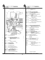
RAISING THE HOOD
To raise the hood (right or left side), release the two
latches, pull up to release.
Then, raise the hood
sufficiently to permit the ratchet type hood rest to engage
and hold the hood open.
Bright Metal Care. Bright metal such as anodized
aluminum, chrome and stainless steel require the same
washing as painted surfaces. A non-abrasive chrome
cleaner may be used sparingly to clean the bright metal.
Do not use steel wool. Use of automobile wax or polish
on bright metal usually will restore the original
brightness.
To close the hood, raise the hood sufficiently to permit
disengagement of the ratchet. Lower the hood slowly.
Engage the two holddown latches.
Upholstery Care. Use a whisk broom and vacuum
cleaner to remove loose dust and dirt from the
upholstery and floor. Vinyl and woven plastic upholstery
can be washed with warm water and mild soap, wipe
dry, If commercial cleaners are used, follow instructions
supplied with cleaner.
LUBRICATION
Have the truck properly lubricated at regular
intervals according to the lubrication instructions and
diagrams shown in this manual.
MAINTENANCE
OPERATOR'S MAINTENANCE
The following pages cover minor servicing and
maintenance instructions which should be performed to
assure efficient operation of the truck.
PAINT,
BRIGHT
MAINTENANCE
METAL
AND
UPHOLSTERY
Frequent and regular washing, will lengthen the life
of your new vehicle's painted finish and bright metal trim.
Washing. Wash your vehicle often with warm or
cold water to remove dirt and preserve the original luster
of the paint. Never wash the vehicle in the direct rays of
the hot sun nor when the sheet metal is hot to the touch,
as this may cause streaks on the finish. Do not use hot
water or strong soaps or detergents or
16
MAINTENANCE
ENGINE OIL
NOTE: Be sure the oil level in the crankcase is
between the "L" (Low) and "H" (High) marks on the
oil dipstick.
OIL FILTER-ENGINE (Auxiliary)
If your vehicle is equipped with an auxiliary oil filter it
has a replaceable element. Proper maintenance and
frequent element replacement will enable the oil filter to
maintain clean lubrication and extend engine life.
Keep oil level as near the high level mark / as
possible. Never operate an engine with oil level below
low level mark.
ENGINE AIR CLEANER (Dry Type)
Check oil level 15 minutes or more after engine is shut
down.
When checking the oil level, the dipstick must be
withdrawn and wiped clean, then inserted all the way
and again withdrawn for a true reading.
Never check the oil level with the engine running as an
inaccurate reading will be obtained.
Use only a good grade and proper viscosity engine oil.
The dry type air cleaner employs a dual dry system,
combining a centrifugal cleaning stage with a special
paper filter.
Do not use oil. Refer to the lubrication instructions
when servicing.
NOTE: Operator must cover air cleaner air intake
opening when servicing chassis to prevent dirt or
foreign matter entering.
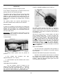
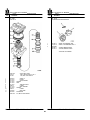
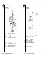
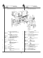
CHANGE FUEL FILTER ELEMENT
REPLACEABLE ELEMENT
1. Remove drain plug from bottom of filter case
and drain contents.
2. Loosen bolt at top of fuel filter. Take out dirty
element, clean filter case and install a new element.
3. Fill filter case with clean fuel to aid in faster pickup of fuel. Install a new gasket in filter head and
assemble case and element. Tighten center bolt to 20 to
25 ft-lbs (2.8 to 3.5 kgm) with a torque wrench.
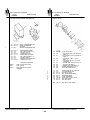
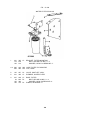
CLEAN FUEL PUMP SCREEN AND MAGNET
1. Loosen and remove cap at top of fuel pump.
Remove spring. Lift out filter screen assembly.
17
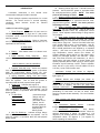
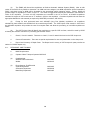
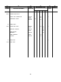
FAN BELT ADJUSTMENT
MAINTENANCE
Always sho-ten distance between pulley centers so
the belt can be installed without force.
2. Separate screen retainer and magnet. On some
units magnet and screen are one integral unit. Magnet
action in filter screen will remove any metal particles that
may enter fuel system.
NOTE: REPLACE BELTS IN COMPLETE SETS
Tighten fan belts so that the pressure of the index
finger will depress as shown.
3. Clean screen and magnet in cleaning solvent
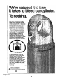
and dry with compressed air.
4. Reassemble magnet in screen. Install filter
screen assembly in fuel pump with hole down.
5. Replace spring on top of filter screen assembly.
6. Replace cap; tighten to 20/25 foot pounds.
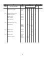
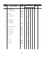
IMPORTANCE OF PROPER OIL
LEVEL
Since the transmission oil cools,
lubricates and transmits power, it is
important that the proper oil level be
maintained at all times. If the level is
too low, the converter and clutches will
not receive an adequate supply. This
can result in poor performance or
transmission failure. If the level is too
high, the oil will foam, causing the
transmission to overheat. Check the
oil level at intervals specified in your
vehicle service instructions, or more
frequently, if operating conditions
indicate. Report any abnormal oil level
to your maintenance personnel.
OIL CHECK PROCEDURE
Before checking the oil level, clean
around the end of the fill pipe before
removing the dipstick. Dirt or foreign
matter must not be permitted to enter
the oil system because it can cause
valves to stick, cause undue wear of
transmission parts or clog passages.
Check the oil level by the following
procedure:
1.
Operate the transmission in a
drive range until normal
operating temperature (160220°F) is reached.
2.
Shift through all drive ranges
to fill the clutches and oil
passages.
Park the vehicle on a level
spot, shift to neutral (N) and
apply the parking brake. Let
the engine run at idle speed.
Check the oil level after
wiping the dipstick clean.
The safe operating level is
between the FULL and ADD
marks on the dipstick.
If not within this range, add or
drain oil as necessary to
bring the level to the FULL
mark.
3.
4.
OIL SPECIFICATIONS
5.
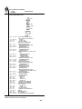
FAN BELT TENSION
BELT WIDTH
1/2"
11/16"
3/4"
7/8"
1"
It is absolutely necessary that the oil
put into the transmission be clean. Oil
must be handled in clean containers,
fillers, etc to prevent foreign material
from entering the transmission.
CAUTION: Containers that have been
used for anti-freeze (ethylene glycol)
should not be used for oil going into
any machinery.
The oil level in the reservoir must be maintained to
the "F" mark on the dipstick type indicator attached to
the filler cap.
By observing the operation of the
transmission and making a few
periodic checks, minor mechanical
problems can be kept from becoming
major overhaul.
If one of these conditions occur• Shifting feels odd.
• Transmission automatically upshifts or downshifts at irregular
intervals.
Notify your
personnel.
vehicle
13/32"
13/32"
7/16"
1/2"
9/16"
POWER STEERING PUMP OIL RESERVOIR
Only Dexron ® automatic transmission
fluid is recommended.
When the
ambient temperature is below - 10°F,
an auxiliary preheat is required. Raise
HOW
TO
KEEP
LITTLE
the temperature above -10°F before PROBLEMS FROM BECOMING
operating the transmission.
BIG PROBLEMS
KEEP OIL CLEAN
DEFLECTION
PER FT. OF SPAN
maintenance
MT17877
18
down to 34 degree F below zero.
permanent type)
MAINTENANCE
Power Steering Oil Reservoir Filter
(50-50 solution of
This factory-fill coolant solution is formulated to
withstand one full year of normal operation without
draining.
A replaceable type filter element is located in the
pump reservoir.
Remove reservoir cover and filter
element. Clean inside of reservoir with lint-free cloth.
Install new filter element and replace cover. Refer to the
lubrication instructions.
Be sure to check the anti-freeze protection level
before cold weather. I.H. Permanent-Type Anti-Freeze
may be added undiluted if protection below -20 degrees
F is required.
ALTERNATOR - Self-Rectifying (Precautions)
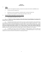
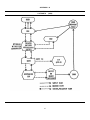
FILLING THE COOLING SYSTEM
Before connecting a fast charger, booster battery or
installing a new battery extreme caution must be used to
make sure that the ground polarities of the fast charger,
booster battery or alternator (when installing a battery)
are matched to the ground polarity of the vehicle battery.
Improper usage of fast charger, hook-up of booster
battery or installing battery can cause damage to the
electrical system or to the alternator.
To eliminate air being trapped within the engine or
heater, the following procedure should be followed when
filling the engine coolant system.
1. Fill cooling system until coolant reaches bottom
of radiator filler opening. Let stand approximately 5
minutes; recheck level.
NOTE: Do not attempt to polarize the alternator.
2. Set parking brake and start engine.
RADIATOR CAP
3. Allow engine to operate without radiator cap at a
fast idle until the engine reaches its normal operating
temperature.
The radiator cap is the pressure-sealing type.
Its
purpose is to maintain the cooling system under slight
pressure, increasing the boiling point of the cooling
solution and preventing loss of the solution due to
evaporation or overflow.
4. After engine reaches its normal operating
temperature, trapped air will be expelled from system.
CAUTION: When removing the pressure type
cap from the radiator perform the operation in two
steps. Loosen the cap slowly to its first notch
position, then pause a moment. This will avoid
possible scalding by hot water or steam. Then
continue to turn the cap to the left until you remove
it.
5. With engine still running, add sufficient coolant
to bring level to approximately one inch below bottom of
filler neck. Install radiator cap.
THERMOSTAT (Cooling System)
The thermostat is the nonadjustable type and is
incorporated in the cooling system for the purpose of
retarding or restricting circulation of water or coolant to
achieve rapid engine warm-up.
The thermostat is
located in the cylinder head water manifold at the water
outlet.
RADIATOR COOLANT LEVEL
Do not fill the radiator completely full. Maintain the
coolant level about one inch below the top of the radiator
upper tank to allow for coolant expansion.
If the coolant in the radiator should get extremely low
and the engine very hot, let the engine cool for
approximately 15 minutes before adding coolant; then,
with the engine running, add coolant slowly. Adding a
large quantity of cold water or coolant to a hot engine
may crack the cylinder head or crankcase.
Engine overheating and loss of coolant is sometimes
due to an inoperative thermostat.
ANTI-FREEZE
RADIATOR SHUTTERS (Automatic)
The cooling system of your new vehicle is filled at
the factory with I.H. Permanent-Type Anti-Freeze and
will protect the cooling system
Automatic
radiator
shutters
maintain
a
predetermined higher engine temperature without
interrupting the coolant flow. This results in greatly
increased engine efficiency and economy as well as
improved heater performance.
When this condition exists, check the thermostat
with an accurate high temperature thermometer by
submerging in hot water.
COOLING SYSTEM CLEANING
Once a year or more often, depending upon the type
of coolant used, the cooling system
19
MAINTENANCE
should be drained and thoroughly flushed.
particularly important before using anti-freeze.
Procedure for servicing the spin-on type water filter is as
follows:
This is
1. Remove water filter assembly by turning
counterclockwise with the hands or a suitable tool.
Clean filter mounting pad.
Unless the water in the cooling system is treated
with a corrosion preventive, rust and scale will eventually
clog up passages in the radiator and water jackets. This
condition is aggravated in some localities by formation of
insoluble salts from the water used.
2. Coat the gasket on the new filter with a film of
grease or oil.
3. Place the new filter in position on the center
tube. Hand tighten 1/2 to 3/4 of a turn after gasket first
contacts base of mounting pad. Do not overtighten.
IH cleaning solutions are available which have
proven very successful in removing accumulation of rust,
scale, sludge, and grease. This solution should be used
according to the recommendation on container.
4. Start engine and check for leaks.
NOTE: Do not use chemical mixtures to stop
radiator leaks except in an emergency. Never use
such solutions instead of needed radiator repair.
When draining the cleaning solution, disconnect
the radiator outlet hose, as large particles of sediment
will not pass through the drain. Also open the drain on
the right side of the crankcase toward the rear of diesel
engines. Drain plugs are located on the right and left
sides near the front on V-8 engines.
WATER FILTER (SPIN-ON TYPE)
If your vehicle is equipped with a cooling system
water filter, filter should be replaced every 10,000 miles
or as necessary to keep the cooling system free of
contaminants.
COLD WEATHER PREPARATION
If the truck is to be operated in temperatures of 32
degrees F, or lower, observe the following precautions:
ENGINE OIL
The intervals at which engine oil must be changed
depend upon the type and quality of oil used, and the
type and severity of the operation. Oil changing is
closely related to filter element and air cleaner cleaning
and changing.
Laboratory tests of used oils, by oil suppliers, will
assist in determining the advisable oil drain period.
AXLE AND TRANSMISSION
Severe cold weather may make it advisable to
change to a lighter grade lubricant in the transmission
and the rear axle differential. A lubricant of lighter
viscosity will provide better lubrication to the moving
parts.
20
MAINTENANCE
costly and troublesome in the long run than haphazard,
unplanned methods.
COOLING SYSTEM
Claims arising from loss and damage that occur
while the vehicle is in storage will not be considered for
reimbursement by the Warranty Processing Center.
For cold weather protection, use a 50-50 solution
permanent type which contains an effective rust
corrosion preventive.
As rapid stock turnover is desirable, sales efforts
should be centered on those vehicles that have been on
hand and in storage for the longest period of time.
Before adding the antifreeze, check the following:
1. Inspect all hoses.
Check for leaks.
Tighten all hose clamps.
Check your own arrangements against the
following suggestions and correct situations which create
unnecessary expense and selling problems.
2. Inspect the water pump for leaks.
Parking Area
3. Inspect the fan belt and adjust to proper tension.
If the belt is worn or oil-soaked, replace it.
Whenever possible, vehicles should be stored
indoors in a dry, well ventilated area and protected from
sunlight. When circumstances do not permit, definite
precautions must be taken \ to eliminate conditions
which would result in product deterioration, unwarranted
expense, and later customer dissatisfaction.
4. Position the vehicle so the engine is level. This
will permit all water to drain from the cooling system.
5. Remove the radiator filler cap and open the
radiator drain; also open the crankcase water drains and
thoroughly drain the cooling system. Then close both
drains and use a recognized cleaning solution, following
the manufacturer's instructions.
CAUTION:
A. Do not park near transformers or electrical
motors, as when the protection wax contained in the
tire compound cracks, ozone in the air will attack the
exposed area.
6. Leave the radiator filler cap off and run the
engine for about one-half hour or until the engine gets
hot. Then disconnect the radiator outlet hose to allow
the larger particles of sediment to pass through; also
open both drains. Drain and flush thoroughly with clean
water.
Close both drains and securely fasten the
radiator outlet hose.
B. Do not park near trees, or where high weeds
or grass exist. This will prevent damage from birds,
tree and week sap or insects which cause stain.
C. Do not park near railroad tracks, industrial
smoke areas, paint shops, or where street and road
splash could contact vehicle.
7. Put the required amount of antifreeze into the
cooling system. Add soft or rain water if available and
inspect the hose connections for leaks.
D. When the vehicle cannot be parked on a level
surface, block wheels.
Do not use calcium chloride or salt solutions.
Body-Cab
TRUCK STORAGE INSTRUCTIONS
A. If necessary wash vehicle. Washing should be
followed by wiping of horizontal surfaces to remove any
water. Never wash the vehicle in the direct rays of the
hot sun nor when the sheet metal is hot to the touch, as
this may cause streaks on the finish. Do not use hot
water or strong soaps or detergents or wipe off dirt when
the surface is dry as this will scratch the paint.
1. General Instructions.
2. Fourth Month Storage Service.
3. Once a Month Storage Service After Four
Months.
1. GENERAL INSTRUCTIONS
B. Avoid waxing or polishing new vehicles. With
the paint material used on present production IH
vehicles, it is definitely harmful to the life of the paint to
use any kind of polish on a new vehicle. Polishes and
combination cleaner and polish waxes all contain
abrasives which cut through the skin of the
Adequate protection and storage of new vehicles is
a strict responsibility of the dealer or branch.
The following procedures are to be used for storing
all vehicles. Satisfactory storage arrangements are less
21
MAINTENANCE
M. Disconnect battery(s) ground cable. This will
prevent accidental starting, or shorting of the electrical
system.
enamel film, thus exposing the pigment to ultra-violet
attack which accelerates chalking and dulling of the
paint.
N. To prevent fading of the interior trim when the
vehicle is exposed to the ultraviolet rays of the sun,
spray or apply a coating of Bon-Ami or similar substance
on the inside of the windshield and windows.
C. Carefully check the paint and touch up all
exposed primed or raw metal surfaces to prevent rust.
D. Clean and wax all chrome and stainless steel
metal parts with a thick coat of custom auto wax to
prevent discoloration from the elements. NOTE: After
each washing be sure that the chrome and bright metal
parts are rewaxed as necessary.
3. ONCE A MONTH STORAGE SERVICE AFTER
FOUR MONTHS.
A. Remove vertical exhaust stack covers.
B. Connect battery(s) ground cable.
2. FOURTH MONTH STORAGE SERVICE
The operations defined below should be performed
on all new vehicles which have been in storage four
months.
C. Start engine and operate at fast idle until normal
engine operating temperature is reached.
Operations To Be Performed
D. Operate air conditioner (if equipped) for a few
moments.
A. Start engine and operate at fast idle until normal
engine operating temperature is reached.
E. IMPORTANT:
Where vehicles are stored
outside, particularly along coastal areas, paint and bright
metal deterioration will be more rapid due to prevailing
salt water atmosphere and high humidity. For this
reason it may be necessary to wash the vehicle and wax
the chrome and stainless steel metal parts once a
month. This operation must be determined by the
branch or dealer.
B. Operate air conditioner (if equipped) for a few
moments.
C. Rinse wash vehicle.
D. Touch up any paint damage.
F. Check tire pressure visually.
E. Clean and wax bright metal.
G. Engage and disengage clutch and parking
brake.
F. Check battery water level and specific gravity.
NOTE: If gravity is under 1.225, recharge battery.
H. Disconnect battery(s) ground cable. This will
prevent accidental starting or shorting of the electrical
system.
G. Check radiator coolant level. Also check coolant
for adequate freeze protection.
H. Install fuel tank rust inhibitor kit No. 285 037
C91 (steel tanks only).
I. Install vertical exhaust stack covers.
I. Check to assure all tires are inflated (visually).
J. Drive vehicle to parking area. Refer to parking
area Cautions outlined under General Instructions.
K. Drain air brake reservoir(s), then close drain
cock.
L. Cover end of vertical exhaust stacks.
22
MAINTENANCE
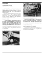
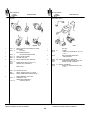
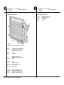
TIRES
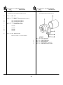
HEADLIGHT REMOVAL
Inflation pressures should be checked when tires are
cool, using an accurate tire pressure gauge. Check
pressures at regular intervals.
Bleeding the air from hot tires is dangerous and
should not be attempted. While the pressure will be
reduced, an increase in temperature of the tire will take
place as soon as driving is resumed and tire failure will
result.
1. Remove the headlight rim retaining screws and
remove the headlight rim.
2. Unhook the headlight retaining spring from the
headlight retainer.
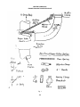
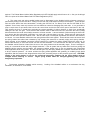
UNDERINFLATION
Too little air pressure increases deflection, causes
the tread to wipe and scuff over the road, results in extra
strain on the tire, and increases the chances for bruising.
PROPER INFLATION
3. Remove the sealed-beam unit from the
headlight and disconnect the three-way connector at the
rear. Hold the three-way connector firmly to avoid
damage to the wiring. Remove the headlight retainer
from the sealed-beam unit.
Maintaining the proper air pressure provides
maximum road contact and results in increased tire life.
OVERINFLATION
4. It is good practice to aim headlights for
maximum illumination for night driving and assure that
the headlight aiming does not conflict with existing laws
and regulations.
Overinflation reduces tire deflection and tire contact
area, causing the tire to ride on the crown, and results in
rapid wear in the center of the tread.
TIRE AND WHEEL BALANCE
Front wheel shimmy, wandering, and cupped tires
are caused by an out-of-balance condition of one or both
front tires. If the tires are changed because of a flat tire
or to equalize wear, it is advised that they be checked for
balance before operating the truck.
IMPORTANT
-
IMPORTANT
-
WHEN INSTALLING REAR WHEELS, BE SURE
HAND HOLE ON INSIDE WHEEL, IS OVER BRAKE
DRUM INSPECTION HOLE.
23
MAINTENANCE
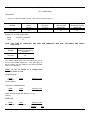
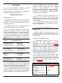
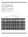
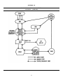
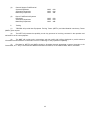
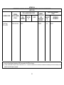
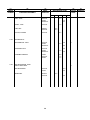
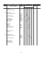
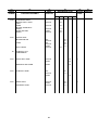
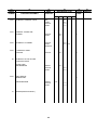
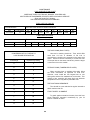
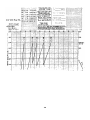
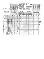
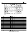
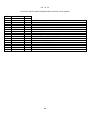
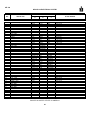
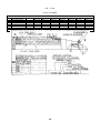
LOAD AND INFLATION CHART
WIDE BASE TIRES FOR TRUCKS, BUSSES, TRAILERS AND
MULTIPURPOSE PASSENGER VEHICLES USED IN HIGHWAY SERVICE
(Bias and Radial Ply Tubeless)
TIRE AND RIM ASSOCIATION STANDARD
TIRES USED AS SINGLES
Tire Identification
Tire Load Limits at Various Inflation Pressures
Size
Load Range
45
50
55
60
65
70
75
80
16.5 x 22.5
H
6590
7010
7410
7790
8170
8540
8890
9230
TIRES USED AS DUALS
Tire Identification
Tire Load Limits at Various Inflation Pressures
Size
Load Range
55
60
65
70
75
80
12.00 x 20
G
4930
5190
5440
5680
5910
6140
NOTE:
For sustained high speed driving over 60 mph, cold inflation pressures must be increased 10 psi
above those specified by the table for the load being carried (but not to exceed 100 psi). Where the 10
psi pressure adjustment for sustained high speed is limited by the maximum of 100 psi, speed must
be limited to 60 mph. (COLD INFLATION PRESSURES MUST NEVER EXCEED 100 PSI.)
TIRE MATCHING (DUAL TIRES)
Use care in matching dual tires. Tires which differ
more than 1/4 inch in diameter of 3/4 inch in
circumference should not be mounted on the same dual
wheel. Should it become necessary to mount two tires
of unequal size on the same dual wheel, place the larger
or less worn tire on the outside.
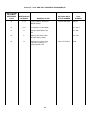
CONVERSION OF PLY RATING TO
LOAD RANGE DESIGNATION
Load Range
Replaces Ply Rating
A
2
B
4
C
6
D
8
E
10
F
12
G
14
H
16
J
18
L
20
M
22
N
24
TIRE MATCHING (TANDEM DRIVE AXLES)
When mounting tires on tandem drive axles, follow
the same instructions as specified for dual tires.
However, never install the four largest tires on one
driving axle and the four smallest tires on the other. This
method of tire mounting will cause high axle lubricant
temperatures which may lead to premature axle failure.
TIRE SWITCHING SEQUENCE
Tires should be cross switched at regular intervals to
attain maximum tire life.
FRONT WHEEL ALIGNMENT
To guard against excessive tire wear, have the front
wheel alignment inspected occasionally by your IH
Branch or Dealer for toe-in.
24
MAINTENANCE
BATTERY
camber, and axle caster.
WHEEL AND RIM MOUNTING NUTS
Disc Wheels
1. Mounting faces of the hub, wheel, and nut must
be free from dirt or excess paint. Mounting faces which
have been damaged from wear or abuse must be
repaired or replaced.
2. Right hand threads are used on the right side of
the vehicle and left hand threads on the left side.
Keep the batteries fully charged and check the
solution level at least every 15 days during hot weather
and 30 days in cold weather.
3. Tighten the wheel nuts alternately.
The solution in each cell should be 3/8" above the
separator plates, or to the indicator level. When the
solution is below this level, add distilled water, using a
clean syringe. Acid or electrolyte should never be added
except by skilled battery personnel.
4. Tighten the single wheel mounting stud nuts to
450-500 foot pounds torque.
5. On dual wheels loosen the outer nuts before
attempting to tighten the inner nuts. Tighten inner nuts
to 500 feet pounds torque and outer nuts to 450 foot
pounds torque.
Under no circumstances should any special battery
"dopes", solution, or powders be added to batteries.
NOTE: Always tighten the inner nuts 50 foot
pounds more than the outer nuts and never let the
outer nuts get below 400 foot pounds.
Test the specific gravity of the electrolyte in each cell
with a hydrometer at least once a month. A hydrometer
reading of 1.260 at 80 degrees F. indicates a full
charge. Never allow the battery to fall below 1.225
which indicates half charged. A discharged battery will
freeze at 20 degrees F. above zero. A fully charged
battery will withstand temperatures as low as 80 degrees
F. below zero.
It is good practice to repeatedly (daily) tighten the
wheel nuts during the first 500 miles of service on new
trucks and any time the wheels have been removed.
Regular inspection periods should be established to
assure keeping the nuts tight.
Battery cable terminals must be clean and tight.
Use hot water and common baking soda for removing
terminal corrosion and for cleaning the top of the battery.
Brighten the contact surface with steel wool, apply a light
coat of vaseline or chassis lubricant, and reassemble.
Be sure the terminals are clamped tightly and that the
battery is clamped securely in the battery box.
When working around the terminals and batteries
use extra care to avoid shorting. A good practice is to
insulate pliers and screwdrivers used with this system.
DO NOT CHECK BATTERY CONDITION BY
SHORTING (FLASHING) ACROSS TERMINALS.
CAUTION: Hydrogen gas is produced in the
normal operation of the battery.
Therefore, to
prevent a fire or dangerous explosion, it is
imperative that flames or sparks (that could be
caused by the use of jumper cables) be kept away
from the vent openings of the battery.
25
LUBRICATION
LUBRICATION DIAGRAM
26
MT-17880
LUBRICATION
Lubrication instructions in this manual
recommended mileage lubrication intervals.
10. Steering Column Slip Joint: Lubricate under low
pressure. Use IH 251H EP grease or equivalent NLGI
#2 multi-purpose lithium grease. NOTE: Too much
pressure will damage oil seals.
11. Steering Column Universal Joint and Pillar Block
Bearing (not shown): Lubricate under low pressure.
Use IH 251H EP grease or equivalent NLGI #2 multipurpose lithium grease. NOTE: Too much pressure
will damage oil seals.
12. Brake Camshafts and Slack Adjusters (Front
and Rear): Do not over-lubricate. Use IH 252 H EP
grease or equivalent NLGI #2 multipurpose lithium
grease. Slack adjusters without fittings or plugs require
no lubrication.
13. Rear Axles, Forward and Rear and Power
Divider: Operate truck; then let stand five minutes
before checking the lubricant level in forward rear axle.
Keep filled to plug level. Drain at first 3000 miles and
every 50,000 miles or twice a year thereafter. Use SP
type lubricant, SAE-90 viscosity year around, meeting
MIL-L-2105B specification and supplied by a reputable
refinery. (SP must not contain zinc.) For abnormally
high temperature, severe service (hot climate, off
highway operation where vehicle is in low speed, heavy
hauling for prolonged periods), use SAE-140. (Keep
axle vents clean and free from obstruction.) In new or
rebuilt axles, add gear lubricant to power divider (see
quantity specified) before initial running to insure proper
lubrication of pinion bearings. NOTE: Traction equalizer
axles, add 20 cc (2/3 ounce) of IH-LS additive for each
0.47 liter (1 pint) of SP lubricant used.
show
These mileages represent requirements for normal
services.
For severe service or unusual operating
conditions, these intervals should be reduced
accordingly.
LUBRICATION INSTRUCTIONS
DAILY
1. Diesel Engines: Crankcase oil level must be
maintained between the "H" (high) and "L" (low) marks
on dipstick. NOTE: Keep oil level as near the high level
mark as possible.
Cummins Diesel Engines: Refer to "Lubricant
and Fuel" following UNIT REFILL CAPACITIES for oil
specifications and viscosity.
AS REQUIRED
2. Battery: Add distilled water to indicator level.
Do not overfill.
3. Power Steering Pump Reservoir:
Keep
reservoir filled to indicator level with SAE 10W-30 engine
oil.
1600 to 3200 km (1000 to 2000 Miles)
4. Propeller Shaft Slip Joint: Under low pressure
force small amount of IH 251H EP grease or equivalent
NLGI #2 multi-purpose lithium grease into joint.
Excessive pressure and lubricant will damage oil seals.
5. Spring Shackles, Spring Pins and Packs:
Lubricate through fittings until old lubricant, dirt and
water are expelled.
Use IH 251H EP grease or
equivalent NLGI #2 multi-purpose lithium grease.
6. Pintle Hook: Lubricate with engine oil.
7. Drag Link Ball Joints: Lubricate through fittings
until old lubricant, dirt and water are expelled. Use IH
251H EP grease or equivalent NLGI #2 multi-purpose
lithium grease.
8. Tie Rod Ends:
( Lubricate through
( fittings until old
Cab Lock Levers:
( lubricant, dirt
(not shown on dia( and water are ex
gram)
( pelled. Use IH
251H EP grease or
equivalent NLGI #2
multi-purpose
lithium grease.
9. King Pin Bushings: Lubricate through fittings
until old lubricant, dirt and water are expelled. Use IH
251H EP grease or equivalent NLGI #2 multi-purpose
lithium grease.
Accelerator Linkage (not shown on diagram):
Lubricate linkage, pivot pins and sliding surfaces with
light engine oil.
Radiator Shutter and Linkage (not shown on
diagram): Vehicles equipped with automatic modulated
control radiator shutters (thermostat element mounted in
bottom tank of radiator), DO NOT OIL PINS AND
SLIDING SURFACES AT FREQUENT INTERVALS.
Vane bearings should be cleaned with light or
penetrating oil and blown out with air ONLY when
servicing complete shutter assembly. Do not oil Cadillac
shutters.
Door Latches and Striker Plates (not shown on
diagram): Lubricate with stick lubricant.
14. Transmission Remote Control:
Lubricate
linkage with light engine oil.
15. Transmission (Automatic):
Only Dexron
automatic transmission fluid is recommended. When the
ambient temperature is below -23 degrees C (-10
degrees F) an auxiliary preheat is required. Raise the
temperature above -23 degrees C (-10 degrees F)
before operating the transmission.
27
LUBRICATION
Oil element very lightly with SAE-30 oil to aid in
capturing dirt particles. Trucks operating under extreme
dusty conditions, service strainer as required.
Transmission (Auxiliary): Keep filled to plug level.
Drain and flush twice each year or every 16,000 km
(10,000 miles). Use straight mineral oil SAE-90 for
temperature -18 degrees C (O degrees F) and up. Use
SAE-80 for temperatures below -18 degrees C (O
degrees F). SPECIAL RECOMMENDATIONS: Where
temperature is consistently below -18 degrees C (O
degrees F) and where parked vehicles are exposed to
unusual cold for long periods, use SAE-75. Where
temperatures are consistently above 32 degrees C (90
degrees F) or unusually hot, use SAE-140 straight
mineral oil.
16,000 to 32,000 km (10,000 to 20,000 Miles)
15. Continued:
21. Fuel Filters (Engines):
Replaceable type
element. Open drain cocks on filter and allow fuel oil to
drain out. Close drain cock. Remove and discard
filtering element. Wash shell with clean fuel oil and
insert new element. Fill cavity between element and
shell two thirds full of clean oil. Install new gasket and
assemble. Remove filler plug at top of filter or strainer
and complete filling with clean fuel. Run engine and
check for leaks at all fuel tube connections.
Fuel Strainer and Fuel Filter: Replaceable type
element. Open drain cocks on filter and allow fuel oil to
drain out. Close drain cock. Remove and discard
filtering element. Wash shell with clean fuel oil and
insert new element. Fill cavity between element and
shell two thirds full of clean fuel. Install new gasket and
assemble. Remove filler plug at top of filter or strainer
and complete filling with clean fuel. Run engine and
check for leaks at all fuel tube connections.
4800 to 8000 km (3000 to 5000 Miles)
16.
Joints:
grease
grease.
seals.
Propeller Shaft and Steering Column Universal
Lubricate under low pressure. Use IH 251H EP
or equivalent NLGI #2 multi-purpose lithium
NOTE: Too much pressure will damage oil
4800 to 9500 km (3000 to 6000 Miles)
22. Oil Filter (Transmission): Change filter element
at transmission lubricant change interval once each year
or every 25,000 miles.
17. Engine Crankcase: Drain and refill (engine hot).
NOTE: More frequent oil changes are required
depending upon the rate of oil contamination caused
by extreme dusty conditions, multi-stop and cold
weather operation. Select oil viscosity grades from
chart.
Door Lock Cylinders (not shown on diagram): Twice
each year or every 20,000 miles, inject 3 or 4 drops of
lock oil through keyhole.
23. Power Steering Pump Filter Element: Every
32,000 km (20,000 miles) remove reservoir cover and
filter element. Clean inside of reservoir with a lint free
cloth. Install new filter element and replace cover.
NOTE: Trucks operating in dusty areas will require
changing the filter element more often.
24. Wheel Bearings (Front): OIL Keep hub filled to
proper level. Clean and inspect wheel bearing and
spindles. Refill with SAE-30 heavy duty engine oil or
rear axle gear lubricant.
Adjust wheel bearings.
CAUTION: Do not pre-load wheel bearing.
25. Wheel Bearings (Rear): GREASE Clean and
inspect wheel bearings and hubs. Repack with IH 251H
EP grease or equivalent NLGI #2 multi-purpose lithium
grease. Adjust bearings. NOTE: Do not mix different
type lubricants. Be certain to thoroughly clean all
old lubricant from bearings and hubs before
repacking.
18. Oil Filter Engine (Full Flow): Remove oil filter
body and element. Clean inside of filter body and install
new element. Operate engine a few minutes and check
filter for leaks.
NOTE:
More frequent element
changes are required depending on the rate of oil
contamination caused by extreme dusty conditions,
multi-stop and cold weather operation.
19. Oil Filter (Engine) (Auxiliary): Every 6000 miles
remove drain plug from bottom of oil filter and drain oil.
Remove oil filter cover, cartridge retaining nut and
cartridge. Clean inside of filter and install new cartridge.
Install cover and drain plug. Add an extra 14 quarts of
engine oil to crankcase to fill filter and cartridge. Start
engine and loosen vent plug in cover. Tighten vent plug
when oil appears at plug. Operate engine a few minutes
and check filter for leaks. NOTE: More frequent
cartridge changes are required depending on the
rate of oil contamination caused by extreme dusty
conditions, multi-stop and cold weather operation.
Window Regulator (not shown on diagram):
Remove door panel and lubricate regulator gear teeth,
pin and slide with IH 251H EP grease or equivalent NLGI
#2 multi-purpose grease.
20. Air Cleaner Strainer (Air Compressor): Remove
element from air cleaner. Replace element if necessary.
28
LUBRICATION
AT REASSEMBLY OR OVERHAUL
Cab Door Check (not shown on diagram): Lubricate
cab door check with IH 251H EP grease or equivalent
NLGI #2 multi-purpose grease.
29. Starting Motor: Lubricate
commutator
end
frame bushing and bushing to drive housing of all
cranking motors with a few drops of engine oil every 500
hours if oil cups or plugs are provided. DO NOT overlubricate. Most cranking motors are semi-permanently
lubricated and require lubrication only at time of engine
overhaul.
25. Continued:
Speedometer and Tachometer Head Oil Wick (not
shown on diagram): Twice each year or every 24,000 to
32,000 km (15,000 to 20,000 miles), place 1 or 2 drops
of 3-in-1 oil or its equivalent in the oil wick cup at rear of
head.
30. Alternator:
Bearings are prelubricated; no
periodic lubrication required. At reassembly or overhaul,
fill bearing reservoir one-quarter full with ball bearing
lubricant.
26. Parking Brake Cylinder:
Every 3 months or
32,000 km (20,000 miles) add 59 cc (2 ounces) of light
engine oil to the brake cylinder through the air inlet.
31. Brake Shoe Anchor Pins and Cams: Do not
over-lubricate.
Coat with IH 2511 EP grease or
equivalent NLGI #2 multi-purpose lithium grease at
assembly.
80,000 km (50,000 miles)
27. Rear Axle:
Drain at 80,000 km (50,000
miles) or twice a year. Use SP type lubricant (SAE-90
viscosity)
year
around,
meeting
MIL-L-2105B
specification and supplied by a reputable refiner. (SP
must not contain zinc.) For abnormally high temperature,
severe service (hot climate, off highway operation where
vehicle is in low speed, heavy hauling for prolonged
periods) use SAE-140. NOTE: Traction equalizer axles
add 20 cc (2/3 ounce) of IH-LS additive for each .47 liter
(1 pint) of SP lubricant used.
32. Water Pump and Fan Hub: At engine overhaul,
disassemble, clean and pack water pump and fan hub
bearings 1/2 to 2/3 full of grease. Use a multi-purpose
industrial grease. If equipped with fittings or plugs
lubricate with a "shot" (tablespoonful) of grease every
20,000 to 25,000 miles.
240,000 km (150,000 Miles)
Or As Required
28. Air Cleaner: Daily inspection of air cleaner dust
cup should be made if dust conditions warrant. Do not
allow dust deposits to build up past a 2" level in cup.
Replace element.
For servicing under 240,000 km (150,000 miles)
observe the following:
Air Pressure Cleaning: Compressed air can be used
to blow out the element from the clean air side out.
Washing Procedure: Filter element can be washed
with any good non-sudsing, household detergent. Use
warm water 49 degrees 60 degrees C (120 degrees 140
degrees F). Flush filter with gentle stream until drain
water is clean. Air dry element before using. ALSO
INSPECT after every cleaning for damage or rupture.
Wipe all internal parts clean before reassembling.
Replace gasket regularly.
29
UNIT REFILL CAPACITIES
(U.S. MEASURES)
CRANKCASE
Engine oil capacities listed in quarts. (See note for special oil pans.)
ENGINE
DRY ENGINE
WITH
FILTER
DRY ENGINE
WITHOUT
FILTER
WET ENGINE
WITH FILTER
SERVICED
WET ENGINE
WITHOUT FILTER
SERVICED
NTC 290
24
--
23
19
ENGINE OIL FILTER - AUXILIARY
CODE
12814
CAPACITY-QUARTS
14
NOTE: FOR TYPE OF LUBRICANT AND FUEL SEE LUBRICANT AND FUEL FOLLOWING UNIT REFILL
CAPACITIES
ENGINE
COOLING SYSTEM
CAPACITY (QUARTS)
(APPROX.)
NTC-290
56
The cooling system should be filled within one inch of
the top of the radiator upper tank. Then run engine for
twenty minutes and refill radiator to the above indicated
level for safe operation.
NOTE: Do not use soluble oil in radiator when
corrosion resistor is used.
TRANSMISSION
Model
T-475 (IH)
HT-750 (Allison)
Code
13475
Capacity, Pints
64
AUXILIARY TRANSMISSION
Model
AT-538
Code
13538
Capacity, Pints
12
Power Steering System with Reservoir 15 qts.
(Approx.)
REAR AXLE
Model
RA-3-U-14368
Code
Tandem Drive
Capacity, Pints
Double Reduction
Forward
Rear
30
28
30
OPERATION
AIR SUSPENSION SEAT
Back Angle
The back rest angle has three (3) positions to
accommodate the driver's preference.
The "Air Viking" seat can be adjusted to each
driver's weight and size.
An easy-to-operate push-pull air valve regulates the
seat to the most comfortable position and weight
adjustment.
Ride Level Indicator
The indicator located inside the left panel provides
positive assurance that the seat is properly adjusted for
the driver's weight.
1. If there is too much air pressure, the indicator (1)
will be forward of the panel edge.
2. If insufficient air exists, the indicator (2) will
remain behind panel edge.
3. Adjust air pressure until indicator (3) is even with
the panel edge.
ADJUSTMENTS
Fore-Aft
The seat assembly moves forward or rearward four
(4") inches along ball bearing slides to suit length of the
driver's legs.
31
OPERATION
for optimum service life during initial 100 hours or 3000
mi. (4827 km) of service by:
1.
Operating as much as possible in half to
three-quarter throttle or load range.
2. Avoiding operation for long periods at engine
idle speeds, or at maximum horsepower levels in excess
of five minutes.
3. Developing the habit of watching engine
instruments closely during operation and letting up on
throttle if oil temperature reaches 250 deg. F (121 deg.
C) or coolant temperature exceeds 190 deg. F (88 deg.
C).
LUBRICATION
4. Operating with a power requirement that allows
acceleration to governed speed when conditions require
more power.
Lubricate the air suspension seat at locations shown
using IH 251H EP grease or equivalent NLGI #2 multipurpose lithium grease.
5. Checking oil level at each 300 mi. (483 km) or
10 hours during the break-in period.
PRE-STARTING INSTRUCTIONS FIRST TIME
PRIMING THE FUEL SYSTEM
1. Fill fuel filter with clean No. 2 diesel fuel oil
meeting the specifications outlined in Section 3.
a. With PT (type G) fuel pump, fill pump through
plug next to tachometer drive with clean fuel.
b. With PT (type G) VS fuel pump, remove suction
line and wet gear pump gears with clean fuel.
2. Check and fill fuel tanks.
ENGINE OPERATING INSTRUCTIONS
3. If injector and valve or other adjustments have
been disturbed by any maintenance work, check to be
sure they have been properly adjusted before starting
the engine.
The engine operator must assume responsibility of
engine care while engine is being operated. There are
comparatively few rules which operator must observe to
get best service from a Cummins Diesel.
PRIMING THE LUBRICATING SYSTEM
NEW AND REBUILT ENGINE BREAK-IN
NOTE: On turbocharged engines, remove oil
inlet line from the turbocharger and prelubricate
bearing by adding 2 to 3 oz. (50 to 60 cc) of clean
lubricating oil. Reconnect oil supply line.
Cummins engines are run-in on dynamometers
before being shipped from the factory and are ready to
be put to work in applications such as emergency fire
trucks.
1. Fill crankcase to "L" (low) mark on dipstick. See
Lubricating Oil Specifications, Section 3.
In other applications, the engine can be put to work, but
the operator has an opportunity to establish conditions
32
OPERATION
2. Remove plug from head of lubricating oil filter
housing (Fig's. 1-1 and 1-2) or filter can to prime
system.
Caution: Do not prime engine lubricating system
from by-pass filter.
3. Connect a hand-or motor-driven priming pump
line from source of clean lubricating oil to plug boss in
housing.
CHECK AIR CONNECTIONS
Check air connections to compressor and air
equipment, as used, and to air cleaners and air
crossovers to assure all are secured.
CHECK ENGINE COOLANT SUPPLY
1. Remove radiator cap and check engine coolant
supply. Add coolant as needed to completely fill system.
See Section 3 for coolant specifications.
2. Make visual check for leaks and open water filter
shut-off valves.
4. Prime until a 30 psi (2.1 kg/sq cm) minimum
pressure is obtained.
5. Crank engine at least 15 seconds (with fuel
shut-off valve closed or disconnected to prevent
starting), while maintaining external oil pressure at a
minimum of 15 psi (1.1 kg/sq cm).
6. Remove external oil supply and replace plug in
lubricating oil filter housing, torque 15 to 20 ft-lbs (2.1 to
2.8 kg m).
STARTING THE ENGINE
Starting requires only that clean air and fuel be
supplied to the combustion chamber in proper quantities
at the correct time.
NORMAL STARTING PROCEDURE
Caution: Clean area of any lubricating oil spilled
while priming or filling crankcase.
If fuel system is equipped with overspeed stop, push
"Reset" button before attempting to start engine.
7. Fill crankcase to "H" (high) mark on dipstick with
oil meeting specifications, listed in Section 3. No change
in oil viscosity or type is needed for new or newly rebuilt
engines.
1. Set throttle for idle speed.
Caution: Protect the turbocharger during the startup by not opening throttle or accelerating above
1000 RPM until normal engine idle speed oil
pressure registers on gauge.
A dipstick oil gauge is located on the side of the
engine. Fig. 1-3. The dipstick has an "H" (high) (1) and
"L" (low) (2) level mark to indicate lubricating oil supply.
The dipstick must be kept with the oil pan, or engine,
with which it was originally supplied. Cummins oil pans
differ in capacity with different type installations and oil
pan part numbers.
2. Disengage driven unit or make sure gears are in
neutral.
3. Open manual fuel shut-down valve, if engine is
so equipped. Electric shut-down valves operate as
switch is turned on.
33
OPERATION
4. Pull the compressions release (if so equipped).
5. Press starter button or turn switch-key to "start"
position.
Caution: To prevent permanent cranking motor
damage, do not crank engine for more than 30
seconds continuously. If engine does not fire within
first 30 seconds, wait one to two minutes before
recranking.
6. A manual override knob provided on the forward
end of the electric shut-down valve allows the valve to
be opened in case of electric power failure. To use,
open by turning fully clockwise; return to run position
after electric repair.
7. After three or four seconds of cranking, close the
compression release (if so equipped) and continue to
crank until the engine fires.
To use the preheater for cold starting:
1. Set throttle in idle position. Do not accelerate
engine during the starting procedure.
2. Turn glow plug toggle switch to "ON" position.
Red indicator light must be on.
3. After red light has been on for 20 seconds, start
cranking the engine. As soon as engine begins rotating,
operate the preheater priming pump to maintain 80 to
100 psi (5.6 to 7.0 kg/sq cm) fuel pressure. Use of
primer before the 20-second interval will wet glow plug
and prevent heating.
Caution: After engine has run for a few minutes,
shut it down and allow time for oil to drain back into
pan. Check engine oil level again; add oil as
necessary to bring oil level to "H" mark on dipstick.
The drop in oil level is due to absorption by the oil
filter and filling of the oil cooler. Never operate the
engine with oil level below the low level mark or
above the high level mark.
NOTE: On engines equipped with an oil pressure
safety switch, the fuel by-pass switch must be in
"start" position before operating priming pump.
Hold the fuel by-pass switch in "start" position until
engine oil pressure reaches 7 to 10 psi (0.5 to 0.7
kg/sq cm); then, move to "run" position.
COLD-WEATHER STARTING
To aid in starting engine when temperature is 50
deg. F (10 deg. C) or below, an intake air preheater is
available. Preheater equipment consists of a handpriming pump to pump fuel into intake manifold, a glow
plug which is electrically heated by battery and a switch
to turn on glow plug. Fuel burns in the intake manifold
and heats intake air. See Fig's. 1-4 and 1-5.
4. If engine does not start within 30 seconds, stop
cranking. Wait one to two minutes and repeat cranking
operation.
5. After engine starts, pump primer slowly to keep
engine idling smoothly. In cold weather this may require
4 to 5 minutes or longer.
Do not accelerate engine.
6. When the engine has warmed up so it does not
falter between primer strokes, stop pumping. Close and
lock primer. Turn off glow plug toggle switch. (Red
indicator light will go out).
Caution: Do not use ether in conjunction with the
preheater. To do so could result in a fire.
34
OPERATION
GOVERNED SPEEDS
All Cummins engines are equipped with governors
to prevent speeds in excess of maximum or
predetermined lower speed rating, except when pushed
by load downhill, etc.
The governor has two functions: First, it provides
the exact amount of fuel needed for idling when the
throttle is in idling position. Second, it overrides the
throttle and shuts off fuel if engine rpm exceeds the
maximum rated speed.
Speeds listed in Table 1-2 are for engines rated at
maximum rpm and fuel rate; many engines are set at
other values due to equipment being powered or loads
applied to equipment and engine.
FAILURE TO START
1. If the engine gives no indication of starting
during the first three full strokes of the preheater pump,
touch-check the intake manifold for heat. If there is no
heat, check electric wiring. If wiring is all right, remove
1/8 inch pipe plug (1, Fig. 1-5) from manifold near glow
plug and carefully check for flame while a helper
performs the preceding Steps 2, 3 and 4.
2. If no flame is observed, close glow plug manual
switch for 15 seconds and observe glow plug through
1/8 inch pipe plug hole. The glow plug should be white
hot; if not, connect wiring to a 6 or 12-volt (as used)
source and check amperage; it should be 30 to 32
(minimum). If glow plug is all right, check manual switch
and resistor (if used) and replace if necessary.
USE THE TACHOMETER
Rated engine speed is the rpm attained at full load.
Governed engine speed is the highest rpm a properly
adjusted governor will allow the engine to turn, no load.
Governed engine speed must never be exceeded on
downgrades or any other condition in which the load
drives the engine.
OIL TEMPERATURE GAUGE
The oil temperature gauge normally should read
between 180 deg. F (82 deg. C) and 225 deg. F (115
deg. C) for best lubrication. Under full load conditions, a
temperature of 250 deg. F (121 deg. C) for a short
period is not to be considered cause for alarm.
ENGINE WARM-UP
When the engine is started, it takes a while to get
the lubricating oil fim re-established between shafts and
bearings and between pistons and liners. The most
favorable clearances between moving parts are obtained
only after all engine parts reach normal operating
temperature. Avoid seizing pistons in liners and running
dry shafts in dry bearings by bringing the engine up to
operating speed gradually as it warms up.
Caution: Any sudden increase in oil temperature
which is not caused by load increase is a warning of
possible mechanical failure and should be
investigated at once.
During warm-up period, apply load gradually until oil
temperature reaches 140 deg. F (60 deg. C). While oil
is cold it does not do a good job of lubricating.
Continuous operation with oil temperatures much below
140 deg.
F (60 deg.
C) increases likelihood of
crankcase dilution and acids in the lubricating oil which
quickly accelerate engine wear.
On some emergency equipment (such as fire
engines) warm-up may not be necessary due to
equipment being housed inside a heated building.
ENGINE SPEEDS
WATER TEMPERATURE GAUGE
IDLE SPEEDS
A water temperature of 165 to 195 deg. F (74 to 91
deg. C) is the best assurance that cylinder liners are
heated to the proper temperature to support good
combustion and that working parts of the engine have
expanded
In most applications engine idle speeds are 580 to
650 rpm; however, the parasitic load may require a
slightly higher value to smooth cut operation.
35
evenly to the most favorable oil clearances.
"Engine Warm-up."
OPERATION
See
ENGINE EXHAUST OBSERVATION
The engine exhaust is a good indicator of engine
operation and performance. A smoky exhaust may be
due to a poor grade of fuel, dirty air cleaner, overfueling,
or poor mechanical conditions.
When water temperature is too low, the cylinder
walls retard heating of air during compression and delay
ignition.
This causes incomplete combustion,
detonation, excessive exhaust smoke and high fuel
consumption.
If engine exhaust is smoky, corrective action should
be taken.
Overheating
problems
require
mechanical
correction. It may be caused by loose water pump belts,
a clogged cooling system, or insufficient radiator
capacity.
Report cases of overheating to the
Maintenance Department for correction. 200 deg. F (93
deg. C) maximum engine coolant temperature should
not be exceeded.
ATTENTION OPERATOR
Cummins Diesel Engines have been built by
Cummins to comply with the requirements of the Federal
(U.S.) Clean Air Act. Proper Maintenance of the Engine,
which is the responsibility of the owner/operator, is
essential to keep emission levels low.
Keep thermostats in the engine summer and winter,
avoid long periods of idling, and take necessary steps to
keep water temperatures up to a minimum of 165 deg. F
(74 deg. C). If necessary in cold weather, use radiator
shutters or cover a part of the radiator to prevent
overcooling. (Refer to "Cold-Weather Operation.")
Once the engine is placed in service the
responsibility for meeting state and local regulations
must necessarily be with the owner/operator.
Observation of good operating practices, regular
maintenance and proper adjustments are factors which
will help stay within the regulations.
OIL PRESSURE GAUGE
The oil pressure gauge indicates any drop in
lubricating oil pressure or mechanical malfunction in the
lubricating oil system. The operator should note loss of
oil pressure immediately and shut down the engine
before the bearings are ruined.
Normal Operating Pressures at 225 deg.
deg. C) are:
Engine
Series
MAXIMUM HORSEPOWER REQUIREMENTS
Maximum horsepower is attained only at rated
engine rpm. Whenever engine rpm is pulled down by
overload, horsepower is lost and continues to be lost as
long as the engine continues to lose rpm. When full
horsepower is needed, operate engine as near rated
rpm as possible. This rule applies to all applications
(except Power-Torque Engines).
F (107
Table 1-2: Oil Pressure PSI (kg/sq cm)
Idle
Rated
Speed
Speed
One rule sums up all rules for proper operation to
give the power needed and best performance from the
equipment:
ALWAYS OPERATE SO POWER
REQUIREMENT WILL ALLOW THE ENGINE TO
ACCELERATE TO, OR MAINTAIN, GOVERNED RPM
WHEN ADVANCING TO FULL THROTTLE.
NH-NT SUPER 250
5/29 (9.4/1.71)
40/75 (2.8/5.3)
For record purposes these readings are more
accurate and reliable when taken immediately after an
oil change.
When more power is required, bring engine speed
near the governor. This will produce the additional
horsepower needed.
NOTE: Individual engines may vary from above
normal pressures. Observe and record pressures
when engine is new to serve as a guide for
indication of progressive engine condition. (High oil
pressure during start-up is not cause for
SHIFT TO A LOWER GEAR WHEN THE LOAD PULLS
DOWN ENGINE RPM
The practice of shifting gears next to safety
observance is a most important phase of good engine
operation.
The shift point differs from unit to unit depending
upon engine rated speed, torque peak point, and
transmission or gear splits
36
OPERATION
available; therefore, it is not always possible to state
exactly at which speed to shift unless all the variable
facts are known. A good rule is "shift down at the same
engine speed the tachometer indicated immediately after
shifting up." On a steep grade, start down-shift before
the engine actually pulls down to shifting speed,
because the truck will lose speed while shifting gears.
EXHAUST BRAKE
So called because closing of a valve in the exhaust
system retains compressions pressures within the
exhaust manifolding and engine cylinders to utilize these
pressures to reduce speed. Compression braking is
most efficient when engine is permitted to turn at same
speeds as for efficient power and may be used as much
and as often as possible.
Failure to shift down at the right time, or a delayed
down-shift will result in the engine failing to reach full
power, and make another down-shift necessary.
JACOBS ENGINE BRAKE
When approaching a hill, open throttle smoothly to
start the up-grade at full power, then shift down as soon
as the engine has dropped to shifting speed. Do not
wait until the engine is below shifting speed. Less gear
shifts will be required and average road speed will be
higher if this is done smoothly.
This braking system converts the engine into a
power absorbing air compressor using a master slave
piston arrangement to open engine exhaust valves near
top of engine compression stroke releasing pressures to
exhaust. The effect being a net energy loss since work
done during compression is not returned during the
expansion process.
DOWNHILL OPERATION
The operator selects a gear which will provide a
balance between engine speed and road speed. If
engine exceeds maximum rated rpm for a designed road
speed, a lower gear can be selected, or intermittent use
can be made of vehicle service brakes. Selection of a
lower gear will generally allow complete control of
vehicle by the brake leaving the service brakes in
reserve for emergency stops.
The Cummins Diesel is effective as a brake on
downhill grades, but care must be exercised not to
overspeed the engine going downhill. The governor has
no control over engine speed when it is being pushed by
the loaded vehicle.
Never turn off the switch key while going downhill. With
the engine still in gear, fuel pressure will build up against
the shut-down valve and may prevent it from opening
when the switch key is turned on.
USE BRAKE AS NEEDED
EXCESSIVE ENGINE SPEEDS
TO
HIGH-ALTITUDE OPERATION
Engines lose horsepower when operated at high
altitude because the air is too thin to burn as much fuel
as at sea level. This loss is about 3 percent for each
1000 ft. (304.8 m) altitude above sea level for a
naturally aspirated engine. Most turbocharged engines
are rated for higher altitudes than naturally aspirated
engines. (See Engine Specification Tables at front of
this manual.) An engine will have a smoky exhaust at
high altitude unless a lower gear is used so the engine
will not demand full-fuel from the fuel system unless the
engine is altitude compensated by the use of a
turbocharger. Shift gears as needed to avoid exhaust
smoke.
PREVENT
Use a combination of brakes and gears to keep vehicle
under control at all times, and to KEEP ENGINE SPEED
BELOW RATED GOVERNED RPM.
AUXILIARY BRAKING SYSTEM
Some trucks are equipped with auxiliary braking
equipment which utilize the engine as a braking device
to reduce wear on the normal truck brake system.
CUMMINS ENGINE COMPANY, INC. WARRANTY
DOES NOT COVER ENGINE DAMAGE RESULTING
FROM USE OF AUXILIARY BRAKING SYSTEMS
SINCE SUCH DAMAGE CAN BE CAUSED BY
IMPROPER APPLICATION, LACK OF MAINTENANCE,
INCORRECT USE OR MALFUNCTION OF SUCH
BRAKES.
37
OPERATION
electric shut-down valve, or by turning the manual shutdown valve knob. Turning off the switch key which
controls the electric shut-down valve always stops the
engine unless override button on shut-down valve has
been locked in open position. If manual override on
electric shut-down valve is being used, turn button full
counterclockwise to stop engine. Refer to "Normal
Starting Procedure," Page 1-2.
Valve cannot be
reopened by switch key until after engine comes to
complete stop.
CAUTION:
NEVER LEAVE SWITCH KEY OR
OVERRIDE BUTTON IN VALVE OPEN OR IN RUN
POSITION WHEN ENGINE IS NOT RUNNING. WITH
OVERHEAD TANKS THIS WOULD ALLOW FUEL TO
DRAIN INTO CYLINDERS, CAUSING HYDRAULIC
LOCK.
ENGINE SHUT-DOWN
DO NOT USE THE COMPRESSION RELEASE LEVER
TO STOP THE ENGINE
IDLE ENGINE A FEW MINUTES BEFORE SHUTDOWN
Some engines are equipped with a compression
release lever. Pulling this lever lifts the intake or exhaust
(depending on engine model) valve push tubes and
opens the valves. The push tubes are lifted off their
sockets and extensive wear on the balls and sockets will
result from using the compression release to stop the
engine.
It is important to idle an engine 3 to 5 minutes before
shutting it down to allow lubricating oil and water to carry
heat away from the combustion chamber, bearings,
shafts, etc.
This is especially important with
turbocharged engines.
The turbocharger contains bearings and seals that
are subject to the high heat of combustion exhaust
gases. While the engine is running, this heat is carried
away by oil circulation, but if the engine is stopped
suddenly, the turbocharger temperature may rise as
much as 100 deg. F (47 deg. C). The results of
extreme heat may be seized bearings or loose oil seals.
The compression release lever can be used as an
aid in cranking, before starting, or while making injector
and valve adjustment, but not i to stop the engine.
STOP ENGINE IMMEDIATELY IF ANY PARTS FAIL
Practically all failures give some warning to the
operator before the parts fail and ruin the engine. Many
engines are saved because alert operators heed
warning signs (sudden drop in oil pressure, unusual
noises, etc.) and immediately shut down the engine. A
delay of ten seconds after a bearing failure causes a
knock, may result in a ruined crankshaft or allow a block
to be ruined by a broken connecting rod.
DO NOT IDLE ENGINE FOR EXCESSIVELY LONG
PERIODS
Long periods of idling are not good for an engine
because operating temperatures drop so low the fuel
may not burn completely. This will cause carbon to clog
the injector spray holes and piston rings.
If engine coolant temperature becomes too low, raw
fuel will wash lubricating oil off cylinder walls and dilute
crankcase oil so all moving parts of the engine will suffer
from poor lubrication.
COLD-WEATHER PROTECTION
1. For cold-weather operation, use of permanenttype ethylene glycol-base antifreeze with rust inhibitor
additives is recommended. See Section 3.
If the engine is not being used, shut it down.
2. To drain cylinder block and head on an Inline 855
Series Engine, open petcock in thermostat housing and
remove drain plug in rear of oil cooler cover or at rear of
block.
TURN SWITCH KEY TO "OFF" POSITION TO SHUT
DOWN THE ENGINE
The engine can be shut-down completely by turning
off the switch key on installations equipped with an
38
OPERATION
some under moderately dusty conditions and others
under severely dusty or dirty conditions; each type of
operation must be analyzed as the maintenance
schedule is established.
OPERATOR'S DAILY REPORT
MAKE A DAILY REPORT OF ENGINE OPERATION TO
THE MAINTENANCE DEPARTMENT
Hours of operation, miles (kilometers), or calendar
period as shown on Page 2-2 are convenient units of
measurement, and should be used to set up the
maintenance schedule interval basis. These periods, as
stated, are based on average operating conditions.
The engine must be maintained in top mechanical
condition if the operator is to get optimum satisfaction
from its use.
Engine adjustments, etc., are the work of the
Maintenance Department. However, the Maintenance
Department needs daily running reports from the
operator to make necessary adjustments in the time
allotted between runs and to make provisions for more
extensive maintenance work as the reports indicate the
necessity.
EXTENDING THE MAINTENANCE SCHEDULE
Any change in the established maintenance
schedule should be preceded by a complete reanalysis
of the operation. A lubricating oil analysis should be the
major factor used in establishing the original
maintenance schedule; it should be studied before
making any change in or extending the schedule
periods. In extremely dirty and under severe operating
conditions, the scheduled maintenance period may even
need reducing. Again the operation should be reanalyzed and a lubricating oil analysis should be made.
Extending or reducing the schedule period should be
done only after a complete study; basically, it should be
the same as used in establishing the original
maintenance schedule period.
Comparison and intelligent interpretation of the daily
report along with a practical follow-up action will
eliminate practically all road failures and emergency
repairs.
Report to the Maintenance Department any of the
following conditions:
1.
2.
3.
4.
5.
6.
7.
Low lubricating oil pressure.
Low power.
Abnormal water or oil temperature.
Unusual engine noise.
Excessive smoke.
Excessive use of coolant, fuel or lubricating oil.
Any fuel, coolant or lubricating oil leaks.
USING THE SUGGESTED SCHEDULE CHECK SHEET
The maintenance schedule check sheet is designed
as a guide until adequate experience is obtained to
establish a schedule to meet a specific operation.
A detailed list of component checks is provided
through several check periods; also a suggested
schedule basis is given for hours of operation, calendar
of time or miles (kilometers) driven.
MAINTENANCE
ENGINE MAINTENANCE SCHEDULE
A maintenance schedule should be established
using the check sheet as a guide; the result will be a
maintenance program to fit a specific operation.
Preventive maintenance performed on schedule is
the easiest, as well as the least expensive type of
maintenance. It permits the Maintenance Department to
do work on schedule, rather than at inconvenient hours.
The check sheet shown can be reproduced by any
printer so the forms may be available for use. The
person making each check can then indicate directly on
the sheet that the operation has been completed. When
a complete column (under A, B, C, etc.) of checks is
indicated, the engine will be ready for additional service
until the next check is due.
Accessories must have a place in the maintenance
schedule the same as the basic engine, for an accessory
failure may put the entire engine out of operation.
Consult accessory manufacturer for maintenance
recommendations.
STORAGE FOR ENGINES OUT OF SERVICE
A GOOD MAINTENANCE SCHEDULE DEPENDS ON
ENGINE APPLICATION
If an engine remains out of service for three or four
weeks (maximum six months) and
Actual operating environment of the engine must
govern the establishment of the maintenance schedule.
Some engines operate under rather clean conditions,
39
MAINTENANCE
its use is not immediately forthcoming,
precautions should be taken to prevent rust.
meet the classification will not provide adequate
protection (varnish and ring sticking) for engines
operated in certain applications.
For example,
turbocharged engines require the additional protection
provided by the CD classification. Engines operated in
stop and go service require the additional protection
provided by the SC classification.
special
Contact the nearest Cummins Distributor for information
concerning engine storage procedures.
LUBRICATION AND FUEL
3. A sulfated as h limit has been placed on all
lubricating oils for Cummins engines because past
experience has shown that high ash oils may produce
harmful deposits on valves that can progress to guttering
and valve burning.
4. Completely ashless oils or high ash content oils,
are not recommended for use in gas engines; a range of
ash content is specified.
LUBRICATING OIL
Lubricating oil is used in Cummins engines to
lubricate moving parts, provide internal cooling and keep
the engine clean by suspending contaminants until
removed by the oil filters.
Lubricating oil also acts as a combustion seal and
protects internal parts from rust and corrosion.
5. SD or SE may be substituted for SC.
The use of quality lubricating oil, combined with
appropriate lubricating oil, drain and filter change
intervals, is an important factor in extending engine life.
Cummins Engine Company, Inc. does not recommend
any specific brand of lubricating oil. The responsibility
for meeting the specifications, quality and performance
of lubricating oils must necessarily rest with the oil
supplier.
BREAK IN OILS
TABLE 3-1: OIL RECOMMENDATIONS
1. Multigraded lubricating oils may be used in
applications
with
wide
variations
in
ambient
temperatures if they meet the appropriate performance
specifications and ash content limits shown in Table 3-1.
Multigraded oils are generally produced by adding
viscosity index improver additives to a low viscosity base
stock to retard thinning effects at operating
temperatures.
Poor quality multigraded oils use a
viscosity index improver additive which has a tendency
to lose its effectiveness after a short period of use in a
high speed engine. These oils should be avoided.
2. Oils which meet the low temperature SAE
viscosity standard (O deg F (-18 deg C) carry a suffix
"W". Oils that meet the high temperature viscosity SAE
standard 210 deg F (99 deg C) as well as the low
temperature carry both viscosity ratings example 2020W. See Table 3-2.
LIGHT SERVICE ONLY
(STOP-AND-GO)
ALL DIESEL MODELS
NATURALLY
ASPIRATED
DIESEL MODELS
AP1 Class CC/SC 2/5
1.85% Maximum
Sulfated Ash Content 3
AP1 Class CC 1
1.85% Maximum
Sulfated Ash Content 3
TURBOCHARGED
DIESEL
MODELS
ALL NATURAL
GAS MODELS
ALL SERVICE
AP1 Class CC/CD 2
1.85% Maximum
Sulfated Ash Content 3
AP1 Class CC
03 to .85%
Sulfated Ash Content 4
Special "Break-In" lubricating oils are not
recommended for new or rebuilt Cummins Engines. Use
the same lubricating oil as will be used for the normal
engine operation.
VISCOSITY RECOMMENDATIONS
1. AP1 classification CC and CD quality oils as
used in turbocharged engines and AP1 classification
CC/SC quality oils as used for stop-and-go service are
satisfactory for use in naturally aspirated engines.
2. AP1 classification CC/SC and CC/CD indicate
that the oil must be blended to the quality level required
by both specifications. The range of oil quality permitted
by the CC classification is so broad that some oils that
TABLE 3-2: OPERATING TEMPERATURES VS VISCOSITY
AMBIENT TEMPERATURES
VISCOSITY
-10 deg. F (-23 deg. C) and
below
-10 to 30 deg. F (-23 to
-1 deg. C)
20 to 60 deg. F (-7 to
16 deg. C)
40 deg. F (4 deg. C) and
above
40
See Table 3-3.
10W
20-20W
30
ARCTIC OPERATIONS
For operation in areas where the ambient temperature is
consistently below -10 deg. F (-23 deg. C) and there is
no provision for keeping engines warm during
shutdowns, the lubricating oil should meet the
requirements in Table 3-3.
Due to extreme operating conditions, oil change intervals
should be carefully evaluated paying particular attention
to viscosity changes and total base number decrease.
Oil designed to meet MIL-L-10295-A, which is void, and
SAE 5W oils should not be used.
TABLE 3-3: ARCTIC OIL RECOMMENDATIONS
PARAMETER
(TEST METHOD)
SPECIFICATIONS
Performance
Quality Level
AP1 class CC/SC
API class CC/CD
SAE Viscosity Grade
10W-20, 10W-30, 10W-40
Viscosity -30 deg. F
(ASTM D-445)
10,000 Centistokes
Maximum
Pour Point
(ASTM D-97)
At least 10 deg. F (6
deg. C) below lowest
expected ambient temperature
1.85 wt. % Maximum
Ash, sulfated
(ASTM D-874)
41
42
MAINTENANCE
ATTENTION OWNER
Your Cummins Diesel Engine has been built by
Cummins to comply with the requirements of the Federal
(U.S.) Clean Air Act. Proper Maintenance of the Engine,
which is your responsibility, is essential to keep emission
levels low. This Section sets forth the maintenance
schedule which you should follow.
TO
PROVE
THAT
YOU
HAVE
PROPERLY
MAINTAINED THE ENGINE YOU SHOULD RETAIN
RECORDS, SUCH AS WORK ORDERS -AND
RECEIPTS;
SHOWING
THAT
SCHEDULED
MAINTENANCE HAS BEEN PERFORMED.
The maintenance record form on this page is for your
convenience.
Maintenance Performance Record
Engine Serial No._________________
Owner Name ____________________
Interval Basis
Mileage
Check
6,000
12,000
18,000
24,000
30,000
36,000
42,000
48,000
54,000
60,000
66,000
72,000
78,000
84,000
90,000
96,000
102,000
A,
A,
A,
A,
A,
A,
A,
A,
A,
A,
A,
A,
A,
A,
A,
A,
A,
B
B
B
B
B, C
B
B
B
B
B, C
B
B
B
B
B, C, D
B
B
Mileage
Check
10,000
20,000
30,000
40,000
A,
A,
A,
A,
B
B
B
B
50,000
60,000
70,000
80,000
90,000
A,
A,
A,
A,
A,
B, C
B
B
B
B
100,000
110,000
120,000
130,000
140,000
150,000
A,
A,
A,
A,
A,
A,
B, C
B
B
B
B
B, C, D
Other
Engine Model ____________________________
Equipment Name/Number __________________
Date
43
Actual
Mileage
Distributor/Dealer
Location/Shop
Authorized
Signature
MAINTENANCE
'A' MAINTENANCE CHECKS
CHECK LEAKS AND CORRECT
Check for evidence of external air, coolant or oil
leakage. Tighten capscrews, fittings, connections or
replace gaskets as necessary to correct. Check oil
dipstick and filler tube caps. Fig. 2-1. See that they are
tightened securely.
If there are indications of air leaks on suction side of
fuel pump, check for air leaks by placing ST-998 Sight
Gauge (1, Fig. 2-2) in the line between fuel filter(s) or
fuel tank and pump. Bubbles or "milky" appearance
indicates an air leak. Find and correct.
CHECK OIL BATH CLEANER OIL LEVEL
ENGINE OIL LEVEL
Daily check oil level in oil bath air cleaner to be sure
oil level in oil cup is at indicated mark. To remove oil
cup, loosen wing nuts. During wet weather and in winter
months, excessive moisture in air cleaner oil sometimes
causes cleaner to become flooded and results in oil pullover or plugging of the bottom air cleaner screen. Add
or change oil as necessary.
1. Check oil level with dipstick oil gauge located on
the engine. For accurate readings, oil level should not
be checked until oil has settled into pan after engine
shut-down. Keep dipstick with the engine and oil pan
with which it was originally furnished. Keep oil level as
near "H" (high) mark as possible.
CHECK COMPLETELY FOR DAMAGE
CAUTION: NEVER OPERATE THE ENGINE WITH OIL
LEVEL BELOW THE "L" (LOW) MARK OR ABOVE THE
"H" (HIGH)MARK.
Visually check fuel system, aneroid (if used), etc. for
misadjustment or tampering, check all systems and
connections for leaks or damage.
2. Add oil as necessary of the same quality and brand
as already in the engine. See Section 3.
44
DUMP BODY OPERATING INSTRUCTIONS
To operate dump body, proceed in the following manner: Bring vehicle to halt, set brakes, put main transmission
into first or any drive gear. Switch dash PTO lever to on position red light will indicate in gear. Move main
transmission shift lever to neutral. Hoist is now ready to be operated. Lift safety latch, located along side of pump
valve lever, move pump valve lever to raise position. Main valve is spring loaded, and must be held in raise or
lower position; if released will return to a hold or neutral position. When unit reaches it's maximum dump angle, it
will automatically pull the control valve to a neutral position.
It is suggested that unit be operated not to exceed 1500 engine rpm's. If you desire to spread or move when
dumping, proceed same as outlined above. Move transmission lever to first gear only, and proceed as slowly as
possible, not to exceed the 1500 engine rpm's.
OPERATION OF AIR BLEEDER VALVE (use only when needed)
Located at top of cylinder is an air bleeder valve. With body raised to raise position, and with safety props put into
sockets, bleeder valve may then be opened to bleed off air in hydraulic system. It is suggested that you use a
pair of hand pliers to open and close thumb pet cock. Due to the vibration of diesel engine, if this is tightened with
bare hands, it sometimes has a tendency to vibrate open, causing an oil leakage. It is, therefore, suggested that
pet cock be snugged with pliers. Use hydraulic oil (Gulf 562 or approved equal). When you check hydraulic oil,
the sight gauge should have approximately one to two inches of oil showing when hoist is in raised position.
When hoist is in down or lower position, sight gauge should show full.
45
LUBRICATION CHART
NO.
1
2
3
4
5
6
7
8
DESCRIPTION
Cylinder
Tail Gate Pins (2)
Body Hinges (2)
Universal Joint
Spline
Universal Joint
Oil Tank Sight Gage
*Oil Reservoir
LUBRICATION FREQUENCY
Monthly*
“
“
Semi-Monthly*
“
“
“
“
Check Daily
Maintain Clean & Full
NOTE: To lubricate universal Joint (4), remove
cover plate under floor mat, (2 Screws) right of
drivers' seat.
*Minimum Requirement.
* Gulf 562 Hydraulic Oil
THIELE, INCORPORATED
WINDBER, PA
15963
PHONE: 814-467-4504
A-1368
46
47
INTERNATIONAL F-5070 6X4 CCE
RECOMMENDED TIE-DOWN POINTS
FORWARD: 1. FRONT TOWING LOOP. (FRAME TIME)
2. FRONT AXLE “I”-BEAM AT SPRING PAD-BOTH SIDES.
REARWARD:3. FRONT AXLE “I”-BEAM AT SPRING PAD-BOTH SIDES.
4. TRAILING REAR AXLE GUIDE BLOCK.
5. PINTLE HOOK. (FRAME TIE)
SIDEWISE:
6. THROUGH WEB OF WHEEL DISC, ANY OR ALL WHEELS.
48
INTERNATIONAL F-5070 6X4 CCE
CABLE SLING LIFT DIAGRAM
NOTE: PLATFORM SLING OR RAMP LOADING IS RECOMMENDED
(F) FRONT TOWING LOOP.
(R) REAR CHAIN TO BE PLACED ABOVE BODY LONGITUDE MEMBERS
49
50
REPEAT STEPS 3, 4, 5 and 6 (see steps 3B, 4B, 5B
and 6B, illustrated in panels to right) except this time
hold the left wheel against the stops and rotate the right
wheel (Steps 4B & 6B).
NOTES ON TESTING:
IF PROPERLY INSTALLED, the rotating (or overturning)
wheel should cam out easily by hand and rotate freely in
both directions and may produce a light indexing or
clicking sound.
WITH THE STANDARD-TYPE NoSPIN, the clicking or
indexing noise is normal and quite prominent as the
driven clutch alternately disengages from the spider and
then reindexes with the spider during the time it is
rotating.
WITH THE SILENT-TYPE NoSPIN, however, any light
indexing noises will be heard and possibly none at all.
The rotating wheel should cam out easily by hand,
should rotate freely in both directions and not reindex
until pressure is relaxed or the direction of rotation
reversed. If you do hear repeated loud indexing or
clicking sounds when checking a silent type NoSPIN,
one of the holdout ring and clutch assemblies may not
be properly assembled to the spider. (If a NoSPIN is
disassembled for any reason, be sure to see the Service
Manual for proper reassembly.)
IF EITHER WHEEL (of either type NoSPIN) DOES NOT
ROTATE OR CAM FREELY IN BOTH DIRECTIONS,
recheck each step in the installation procedure. Also,
check both hand and foot brakes for possible drag
caused by improper adjustment. Check again to be sure
that all thrust washers have been removed.
51
NEW MOTOR VEHICLE WARRANTY
FLEETSTAR SERIES AND LARGER
International Harvester Company warrants to the first user purchaser of each new International motor vehicle that it is free
from defects in material and workmanship under normal use and service, its obligation under this warranty being limited to
repairing or replacing, as the Company may elect, any part or parts thereof, including all equipment or trace accessories
(except tires and tubes and diesel engines not manufactured by the Company as these items are warranted separately by
their respective manufacturers) supplied by the International Harvester Company, which shall be returned to the seller's
place of business, or if the first user purchaser is in transit or has moved, to the most convenient International Truck
Dealer authorized to handle motor vehicles of the model covered by this warranty, with transportation charges prepaid,
and as to which examination shall disclose to the Company's satisfaction to have been thus defective, provided that such
part or parts shall be so returned not later than twelve (12) months after delivery of such vehicle to the first user
purchaser, and that at the time of such return, the said vehicle shall not have been operated in excess of fifty thousand
(50,000) miles, or, if the engine is also used as a power source for other than propelling the vehicle, the engine shall not
have been used or operated in excess of three thousand (3,000) hours of operation. Such defective part or parts will be
repaired or replaced on a pro-rata basis to the first user purchaser at the seller's place of business or if the first user
purchaser is in transit or has moved, to the most convenient International Truck Dealer authorized to handle motor
vehicles of the model covered by this warranty. The amount of prorated credit allowable for repairing or replacing any
such defective part including the cost of installation shall be a percentage of the servicing location's price of the parts and
labor charges to the first user purchaser, such amount to be determined by using the percentage indicated in the following
chart which applies to the greatest period of service:
MILES, MONTHS AND HOURS OF SERVICE, WHICHEVER IS GREATEST
Miles
0-12,000
12,001-20,000
20,001-30,000
30,001-40,000
40,001-50,000
Over 50,000
Months
Hours
12
12
12
12
12
Over 12
0 - 360
361 - 600
601 - 900
901 - 1,200
1,201 - 1,500
Over 1,500
Percentage of Part
and Labor Price
Allowable to Purchaser
100%
80%
60%
40%
20%
0%
This warranty shall not apply (1) to normal maintenance services or adjustments, including but not limited to, fuel system
cleaning, wheel alignment and balancing, engine tune-up, brake inspection or adjustment, nor to the replacement of spark
plugs, ignition points, condensers, lubricants and filters when such replacements or adjustments are made as part of any
such normal maintenance service, (2) to any vehicle which shall have been repaired or altered outside of a Company
authorized service center in any way so as, in the Company's Judgment, to affect adversely its stability or reliability, nor
which has been subject to misuse, negligence or accident, nor to any vehicle which shall have been operated at a speed
exceeding the factory rated speed, or loaded beyond the factory rated load capacity, (3) to any vehicle on which the
odometer has been disconnected or the mileage reading has been altered and the vehicle's actual mileage cannot be
readily determined, or (4) to any minor service adjustment or repair requiring less than twenty-five ($25.00) parts and
labor to complete provided the vehicle had been operated in excess of 12,000 miles.
FIVE STAR WARRANTY ON MAJOR COMPONENTS
International Harvester Company also warrants to the first user purchaser that the following listed components purchased
as original equipment on a new International motor vehicle, are free from defects in material and workmanship under
normal use and service for twenty-four (24) months from date of delivery to the first user purchaser or one hundred
thousand (100,000) miles of operation, or, if the engine is also used as a power source for other than propelling the
vehicle, until it has been used or operated for three-thousand (3,000) hours of operation, whichever first occurs:
Basic engine (from crankshaft pulley to and including flywheel and water pump, including fuel injection pump,
turbocharger, injectors, but excluding all other fuel, cooling, electrical, and filtration system components, and all
other attaching accessories, and also excluding Detroit Diesel, Cummins and Caterpillar engines)
52
Main transmission, auxiliary transmission and transfer case less controls and attachments. Rear axle housing,
differential, power divider and non-driving rear axle (less wheel ends, axle shafts, controls and attachments).
Main frame.
Front axle "I" beam, front drive axle housings and differential (less outer ends).
International Harvester Company's obligation under this extended warranty shall be limited to allowing credit to the first
user purchaser on a pro-rata basis, for any parts which shall be returned to the seller's place of business, or if the first
user purchaser is in transit or has moved, to the most convenient International Truck Dealer authorized to handle motor
vehicles of the model covered by this warranty with transportation charges prepaid and as to which examination shall
disclose to the Company's satisfaction to have been thus defective. The amount of prorated credit allowable for repairing
or replacing any such defective part including the cost of installation shall be a percentage of the servicing location's price
of the parts and labor charges to the first user purchaser, such amount to be determined by using the percentage
indicated in the following chart which applies to the greatest period of service.
MILES, MONTHS AND HOURS OF SERVICE, WHICHEVER IS GREATEST
Gasoline Engine and all other Warranted Components---
Miles
Months
Hours
Percentage of Part
and Labor Price
Allowable to Purchaser
12,001-25,000
25,001-50,000
50,001-75,000
75,001-100,000
Over 100,000
More than 12, but less than 15
15 or more, but less than 18
18 or more, but less than 21
21st through 24th month
Beyond 24th month
361 - 800
801 - 1,500
1,501 - 2,200
2,201 - 3,000
Over 3,000
80%
60%
40%
20%
0%
IH Diesel Engine Only---
Miles
12,001- 50,000
50,001-100,000
Over 100,000
Months
More than 12, thru 24th
More than 12, thru 24th
Beyond 24th Month
Hours
361 - 1,500
1,501 - 3,000
Over 3,000
Percentage of
Parts Price
Allow. to Purch.
100%
100%
0%
Percentage of
Labor Price
Allow. to Purch.
100%
50%
0%
This warranty shall not apply (1) to normal maintenance service or adjustments; (2) to any vehicle which shall have been
repaired or altered outside of a Company authorized service center in any way so as, in the Company's judgment, to
affect adversely its stability or reliability, nor which has been subject to misuse, negligence or accident, nor to any vehicle
which shall have been operated at a speed exceeding the factory rated speed, or loaded beyond the factory rated load
capacity; or (3) to any vehicle on which the odometer has been disconnected or the mileage reading has been altered and
the vehicle's actual mileage cannot be readily determined.
THESE WARRANTIES ARE IN LIEU OF ALL OTHER WARRANTIES, EXPRESSED OR IMPLIED (OTHER THAN THE
COMPANY'S EMISSION CONTROL SYSTEMS WARRANTY) INCLUDING WITHOUT LIMITATION WARRANTIES OF
MERCHANTABILITY AND FITNESS FOR PARTICULAR PURPOSE, ALL OTHER REPRESENTATIONS TO THE FIRST
USER PURCHASER, AND ALL OTHER OBLIGATIONS OR LIABILITIES, INCLUDING LIABILITY FOR INCIDENTAL
AND CONSEQUENTIAL DAMAGES, ON THE PART OF THE COMPANY OR THE SELLER. No person is authorized to
give any other warranties or to assume any other liability on the Company's behalf unless made or assumed in writing by
the Company, and no person is authorized to give any warranties or to assume any liabilities on the seller's behalf unless
made or assumed in writing by the seller.
International Harvester Company
53
WARRANTY
PLEASE KEEP THIS PORTION OF THE WARRANTY
CARD
DETROIT AUTOMOTIVE
Should your NoSPIN require replacement due to
any of the circumstances covered by our Warranty on
the reverse side of this card, you may use either of the
following methods to receive immediate satisfaction:
return the complete differential, along with this card to
your nearest authorized NoSPIN Distributor, or write for
a Returned Material Data Form, fill it out and include the
form when you ship the unit directly to the factory, freight
prepaid and insured. All replacement merchandise will
be shipped to you freight collect. Sorry, we are not
responsible for labor charges incurred for removing or
installing.
Each new NoSPIN differential or new parts for
same are warranted by Detroit Automotive to be free
from defects in material and workmanship under normal
recommended use and service for same period (of time,
mileage or hours of use) as the other axle parts are
warranted by the axle manufacturer provided failure is
not caused by wear to or failure of other axle parts. The
Company's obligation under this warranty is limited to
making good at its factory any NoSPIN differential
assembly or parts thereof which shall be returned to it,
and which Company's examination shall disclose to its
satisfaction to have been thus defective.
MODEL ___________ DATE PURCHASED__________
YOUR NAME__________________________________
ADDRESS____________________________________
CITY__________________ STATE______ ZIP_______
DEALER'S NAME______________________________
ADDRESS____________________________________
CITY__________________ STATE______ ZIP_______
This warranty shall not apply to any unit which
has been subject to misuse, negligence or accident, or
which has been repaired or altered outside the
Company's factory in any way which would affect its
stability or reliability.
When an adjustment is sought, by reason of the
above warranty, claim must be made in writing on the
standard Returned Material Data Form which is
furnished upon request. All information requested on the
form must be received by Detroit Automotive before
returned material can be accepted. The entire NoSPIN
assembly or parts thereof should then be returned
prepaid, for analysis of the reported failure.
Strict
compliance with these requirements is necessary for
proper consideration of each warranty claim.
Detroit Automotive, 11445 Stephens Drive, Warren,
Michigan 48090
IMPORTANT:
RETURN THIS PORTION OF THE WARRANTY CARD.
In order for your warranty to be valid, this portion of the
warranty card must be accurately filled out and returned
to the factory no later than 14 days after the date of
purchase. Failure to comply will forfeit all warranty
privileges.
THIS WARRANTY SHALL BE EXPRESSLY IN
LIEU OF ALL OTHER WARRANTIES, EXPRESS OR
IMPLIED, INCLUDING THE WARRANTIES OR
FITNESS AND MERCHANTABILITY.
NoSPIN MODEL NUMBER_______________________
DATE NoSPIN INSTALLED_______________________
AT SPEEDOMETER READING OF___________MILES
VEHICLE (Make, Model and Serial Number) TO
WHICH NoSPIN WAS ADAPTED__________________
_____________________________________________
MAXIMUM GROSS VEHICLE WEIGHTS:
Chassis__________ Body_________ Payload________
DISTRIBUTOR or DEALER FROM WHOM NoSPIN
WAS PURCHASED
NAME________________________________________
ADDRESS____________________________________
CITY and STATE____________________ ZIP________
VEHICLE OWNER______________________________
(Corporation or Individual)
OWNER'S ADDRESS___________________________
OWNER'S SIGNATURE_________________________
DATE________________________________________
Detach and return to Detroit Automotive.
54
CUMMINS WARRANTY
satisfaction of Cummins to have been defective and that
is returned, with transportation charges prepaid, to the
Cummins factory in Columbus, Indiana, or to a
Distributor or Dealer authorized by Cummins to perform
warranty repairs.
100,000 MILES, 3,600 HOURS, TWO YEARS
This warranty applies to highway engines and
marine main propulsion engines marketed for use in the
United States or Canada under the trademark
"Cummins".
None of the warranties stated herein apply to (i)
any engine that shall have been subject to
overspeeding, misuse, negligence, or accident, (ii) any
engine that shall have been repaired or altered by
anyone who is not an authorized Cummins Distributor or
Dealer in such a way that, in the judgment of Cummins,
its performance and reliability are adversely affected, (iii)
any part of an engine improperly applied or installed, (iv)
failures in any way resulting from use of parts not
manufactured or approved by Cum-ins, or (v) normal
maintenance services including, but not limited to,
engine tune-up and the repair or replacement of filters
and belts.
Cummins engines are warranted to be free from
defects in workmanship and material, under normal use
and service, for two years or 100,000 miles or 3,600
hours of operation, whichever shall occur first, from the
date of delivery to the first purchaser, but subject to the
following conditions.
Until the engine shall have
achieved 10,000 miles or 1,800 hours of operation,
whichever shall occur first, from the date of delivery to
the first purchaser, Cummins will bear reasonable labor
costs required to repair or replace any part found by it to
be defective as stated below, provided the repairs or
replacements are made by Cummins at its plant in
Columbus, Indiana, or by an authorized Distributor or
Dealer at the place of business of such Distributor or
Dealer.
Thereafter, and for the remainder of this
warranty, Cummins, at its sole option, may pay a portion
of such labor costs. This warranty does not include
engine removal and reinstallation expense.
Cummins shall not be liable for loss of time to
the user while the engine or other equipment is out of
commission.
Starters, generators, transmissions, clutches,
radiators, and other accessory items not manufactured
by Cummins are warranted by their respective
manufacturers, and are not warranted by Cummins.
EMISSION WARRANTY
There are no warranties, express or implied,
including warranties of merchantability or fitness for a
particular purpose, by Cummins or any Distributor or
Dealer, regarding Cummins engines (as defined above)
except the warranties specified herein. No person is
authorized to bind Cummins for any such other warranty.
In addition to the foregoing, Cummins warrants
to the ultimate purchaser and each subsequent
purchaser that each engine which is manufactured on or
after January 1, 1972, and which is in a vehicle designed
for transporting persons or property on a street or
highway, is designed, built and equipped so as to
conform at the time of sale by Cummins with all U.S.
Federal emission standards applicable at the time of
manufacture and that is free from defects in materials
and workmanship which would cause it not to meet
these standards within the period of five (5) years,
100,000 miles, or 3,000 hours of operation, whichever
occurs first, as measured from the date of delivery of the
engine to the ultimate purchaser. Failures, other than
those resulting from defects in materials or
workmanship, which arise solely as a result of owner
abuse and/or lack of proper maintenance are not
covered by this warranty.
NOTE:
The responsibility of Cummins under these
warranties is limited to repairing or, at its option,
replacing, subject to the provisions set forth above, any
part that, upon examination is disclosed to the
55
HYCO, INC.
CLAIMS, WARRANTIES, DEFECTIVE MERCHANDISE
We warrant the merchandise furnished by us to
be free from defect in material and workmanship. No
other warranty, express or implied, whether of fitness,
merchantability or of any other kind, shall exist, all such
warranties being waived by Buyer. Upon receipt of
notice of any claim by the Buyer for defects in
workmanship or material, we shall have the option, to be
exercised immediately, either of inspecting any allegedly
defective merchandise in the Buyer's hands or of
requesting its return to us. We will, at our option either
repair, replace or give Buyer proper credit for
merchandise determined by us to be defective. Such
repair, replacement, or credit shall constitute our sole
obligation under this warranty, and we shall not be liable
for damages or losses resulting directly or indirectly from
the use, or resale by Buyer, of defective merchandise,
nor shall we be liable in any way with respect to
merchandise which has been further processed. In the
event any liability shall be imposed on us by law for our
negligence, if any, in the production or delivery of the
items covered by this Agreement, the damages
recoverable in such case by Buyer, or anyone claiming
through Buyer, shall in no event exceed damages
sustained by Buyer on account (1) of bodily injuries, and
(2) physical injury to or destruction of property. In no
event shall we be liable for loss by Buyer, its customers
or the users of its products, of the use of any equipment,
physically injured or destroyed or for any loss of revenue
or profits resulting from damage to such equipment.
56
PART TWO
REPAIR PARTS INFORMATION
AND
SUPPLEMENTAL MAINTENANCE INSTRUCTIONS
USER MAINTENANCE SUPPORT PLAN
FOR
TRUCK, DUMP, 20 TON, 6 X 4, ON-OFF
HIGHWAY, 71000 GVW, CCE
NSN 3805-00-192-7249
TABLE OF CONTENTS
SECTION
Paragraph
I
1-1
1-2
1-3
APPENDIX
1-A
1-B
1-C
1-D
SECTION
II
Paragraph
2-1
2-2
2-3
2-4
2-5
2-6
2-7
2-8
2-9
2-10
2-11
2-12
2-13
2-14
2-15
2-16
2-17
2-18
2-20
INTRODUCTION
Page No.
Scope
Milstrip Requisition Identification
and Controls
Maintenance Forms and Records
Flow of Requisition and Material,
CCE Parts (FSN)
Flow of Requisition and Material,
CCE Parts (Non-FSN)
Non-FSN, MILSTRIP Requisition for CCE,
Sample Format
NSN-MILSTRIP Requisition for CCE,
Sample Format
1
1-2
3
4
5
6
7
MAINTENANCE SUPPORT DATA
Purpose
Description
Supporting Data
Procurement Status
Condition of Employment
Maintenance Concept
Using Organization
Support Organization
Support Equipment .
Repair Parts and Support
Personnel and Training
The Army Maintenance Management System (TAMMS)
Facilities
Technical Assistance
Reliability and Maintainability
Requirements
Warranty
Equipment Improvement Recommendations
(EIRs)
Destruction to Prevent Enemy Use
Shipment and Storage
i
8
8-9
9
10
10
10-12
12-13
13
13
13-16
16-17
18
18
18
19
19
19
19
19
Page No.
2-21
2-22
2-23
2-24
APPENDIX
2-A
2-B
2-C
2-D
2-E
2-F
2-G
2-H
2-I
2-J
2-K
2-L
2-M
2-N
Manufacturer's Field Campaigns and
Modification
Basic Issue Item List
Maintenance and Operating Supply List
Supplement Operating Maintenance and
Repair Parts Instructions
Supporting Data for Major and Secondary
Maintenance Allocation Chart (MAC)
Overhaul and/or Rebuild of CCE End
Items
Deleted
CCE Manufacturer Field Campaigns and
Modification Procedures
Basic Issue Item List and Items Troop
Installed or Authorized List
Maintenance and Operating Supply List
Preventive Maintenance Checks and Services
MERADCOM, Information Package
Revision No. 175 Special Parts Catalog
Warranty
Color Coding
PLL and ASL
Special Tools
ii
19
20
20
20
21
22-49
50
51
52
53-57
58
60-75.
76-204
205-220
221
222
224-226
227
SECTION I
INTRODUCTION
1-1.
SCOPE
The instructions in this supplemental operating, maintenance and repair parts instructions (SOMARPI) are for:
1-2.
a.
The user of the 20 Ton Dump Truck.
b.
Maintenance personnel responsible for maintaining and/or re pairing the Dump Truck.
c.
Supply personnel responsible for requisitioning and stockage of repair parts.
MILSTRIP REQUISITION IDENTIFICATION AND CONTROL
a.
Parts Requisition Identification and Control
(1)
A combination of Project and Weapon System Codes will be used for identification and controls of CCE
parts requisitions. Three (3) CCE Project Codes and a unique Army Weapon System Designator Code (WSDC) are
assigned to the CCE Dump Truck.
(2)
The purpose and intended use of the CCE Project Code is to identify manufacturer's part numbered items
to the Defense Construction Supply Center (DCSC) for the action DCSC will take in support of the CCE Plan. A CCE
Project Code will be used on all non-NSN requisitions and routed to DCSC. The CCE Project Code will have a. two-fold
meaning: (1) to identify the requisition to a specific CCE end item, and (2) to identify the routing of parts shipments either
by the Direct Support System (DSS) procedures, or by non-DSS procedures. National Stock Numbered (NSN) items
identified in the initial recommended Prescribed Load List and Authorized Stockage List (PLL/ASL) as well as non-stocked
NSN items will use the standard supply system and DSS assigned codes when applicable, on the requisition.
(3)
The WSDC will be used on all parts requisitions (NSN or non-NSN) submitted for support and will be used
in conjunction with the Logistics Intelligence File (LIF) in accumulation of Demand/Consumption, Life Cycle Costing
Analysis and to provide and overview of the CCE Plan for reporting and analysis.
1
b.
Codes.
(1)
CCE Project Code.
CODE DEFINITION
XDX
(USAREUR)
Indicates the requisition is in support of CCE and designates part
shipments to the East Coast Consolidation/Containerization Point
(New Cumberland Army Depot).
XDL
(USARPAC)
Indicates the requisition is in support of CCE and designates parts
shipments to the West Coast Consolidation/Containerization Point
(Sharpe Army Depot).
XDO
(CONUS)
(USARAL)
(USARSO)
Indicates the requisition is in support of CCE but will be treated as
non-DSS. Parts shipments will be made directly from Depot/Vendor to
requisitioners.
(2)
WEAPON SYSTEM DESIGNATOR CODE (WSDC)
"7X" is the assigned WSDC for the Dump Truck.
(3)
DISTRIBUTION CODE
Code "F" will be cited in Card Column (CC) 54 for all CONUS only requisitions.
All OCONUS will cite the applicable code as cited in AR 725-50.
c.
MILSTRIP Requisition Card Column (CC Entries.)
(1)
NSN Requisitions: See Appendix 1-D for CC entries.
(2)
Non-NSN Requisitions: See Appendix 1-C for CC entries.
d.
Requisitioning and Flow of Requisitions.
2
1-3.
(1)
NSN Requisitions: See Paragraph 2-10 titled "Repair Parts and Support" and Appendix 1-A.
(2)
Non-NSN Requisitions: See paragraph 2-10 titled "Repair Parts and Support" and Appendix 1-B.
MAINTENANCE FORMS AND RECORDS
DA Forms and procedures used for the equipment Maintenance Records will be those prescribed in section II,
paragraph 2-12 of this SOMARPI.
3
APPENDIX 1-A
FLOW OF REQUISITIONS AND MATERIEL
CCE PARTS
(NSN)
4
APPENDIX 1-B
FLOW OF REQUISITIONS AND MATERIEL
CCE PARTS
(NON-NSN)
5
APPENDIX 1-C
NON-NSN SAMPLE FORMAT
MILSTRIP REQUISITION FOR CCE
CARD COLUMN
1-3
Document Identifier Code
4-6
Routing Identifier Code
7
8-22
23-22
25-29
30-43
44
45-50
51
52-53
54-56
57-59
60-61
62-64
65-66
67-69
70-80
MANDATORY ENTRY
FOR CCE
DESCRIPTION OF DATA
A∅B - CONUS
A∅2 - Overseas
Always S9C
Media/Status Code
Part Number
Unit of Issue
Quantity
Document Number
Demand Code
Supplementary Address
Signal Code
Fund Code
Distribution Code CC-54
CC-55-56
Project Code
Priority Code
Required Delivery Date
Advice Code
Blank
Blank
6
“F” For CONUS
Weapon System Code
CCE (DSS) Code
APPENDIX 1-D
NSN SAMPLE FORMAT
MILSTRIP REQUISITION FOR CCE
CARD COLUMN
1-3
4-6
7
8-22
23-24
25-29
30-43
44
45-50
51
52-53
54-56
57-59
60-61
62-64
65-66
67-69
70-80
MANDATORY ENTRY
FOR CCE
DESCRIPTION OF DATA
Document Identifier Code
A∅A-CONUS
A∅1-Overseas
Routing Identifier Code
Media/Status Code
FSN
Unit of Issue
Quantity
-Document Number
Demand Code
Supplementary Address
Signal Code
Fund Code
Distribution Code
CC-54
CC-55-56
Project Code
Priority Code
Required Delivery Date
Advice Code
Blank
Blank
7
"F" For CONUS
Weapon System Code
SECTION II
MAINTENANCE SUPPORT DATA
MSP No. 5-3805-254
2-1.
February 1974
PURPOSE
The Dump Truck is a 20 ton on-off highway, 71000 Gross Vehicle Weight Rating (GVWR) and is to be used for
transporting materials for the construction/rehabilitation of roads, airfields, ports, beach and marine POL facilities worldwide.
2-2.
DESCRIPTION
a.
The Dump Truck is a 20 ton, 6 x 4, 71000 GVWR on-off highway model with a 12 cubic yard struck (water
level) capacity rear dump body on a conventional. commercial design and heavy duty constructed chassis. The dump
truck will carry a payload of 40000 pounds. It has at GVWR, a geared high speed capability of 40 mph minimum and a
low speed and torque capability to ascend, stop and restart on a 30 percent grade. The dump body is an extra heavyduty contractor's type, engine exhaust heated with a diverter valve, double action offset top hinge manual control tailgate,
front telescopic type hoist system, with a hydraulic control lock and manual safety strut, a gear type hydraulic pump and a
25 micron type filter. The front tire and rim assembly differ in size and configuration. Spares (front and rear) are furnished
as Prescribed Load List (PLL) items and as an assembled component.
b.
It will perform:
(1)
Short haul dumping cycles on secondary roads of under 3 miles for at least 10 hours without refueling.
(2)
Long haul dumping cycles on secondary roads and sustained average high speeds of 40 mph for a
minimum of 200 miles without refueling.
(3)
It will provide a balanced axle weight distribution At GVWR without any axle exceeding its rated load or
26,500 pounds, whichever is lower.
8
(4)
The operator of the vehicle conducts the operation of the dump body and tailgate from within the cab.
c.
Dimensions.
The dimensions of the Dump Truck are as follows:
Overall length
Overall width
Overall Height
Wheelbase
Bumper to back of cab
Cab to axle
Interior size of cab
Axleweight
319 inches
101 inches
125 inches
184 inches
114 inches
120 inches
69 inches X 57 inches
Front: 12,700 lb.; Rear: 18,300 lb
(5)
Operational and maintenance procedures are covered in the manufacturer's manuals overpacked with the
equipment. The category of maintenance for the dump truck will be in accordance with Maintenance Allocation Chart
(MAC). (See Appendix 2-B of the SOMARPI) Refer to paragraph 2-10 of this SOMARPI for requisitioning of repair parts
and support. The intended uses are as follows:
(a)
Intended Use.
The dump truck is primarily intended for use in transporting materials for the construction/rehabilitation of roads,
airfields, ports, beach and marine POL facilities world-wide. It is capable of providing rapid transport of capacity payloads
in mud, sand, snow and off-road terrain, with and without payload, up to the limit of traction. The equipment that may be
serviced by the dump truck are:
Concrete Pavers
Asphalt Spreaders
Chip Spreaders
Rock Crushers
Conveyers
Storage Bins
Asphalt Pug Mills
Motorized Bucket Loaders, 2-1/2 thru 6 cubic yard sizes
Powered excavators up to 2 cubic yard size
2-3.
SUPPORTING DATA
See Appendix 2-A.
9
2-4.
PROCUREMENT STATUS
a.
This is a multi-year (5 year) procurement.
b.
The procurement was awarded under contract DSA 700-72-C-9235.
c.
Quantity procured for FY 72-140 each and 140 for each succeeding 5 fiscal year. A total of 700 dump
trucks.
2-5.
CONDITIONS OF EMPLOYMENT
a.
The dump truck is capable of being operated, stored and used in wet-warm, wet-hot, intermediate hot-dry
and cold climatic conditions.
b.
Turn around cycle for the dump truck is:
(1)
Short hauls (3 miles) 1 hour.
(2)
Long hauls (200 miles) 8 hours.
c.
The Department of the Army (DA) approved mission profile is 12000 miles per year with daily usage or 8 10 hour shifts.
d.
Perform variable dumping cycles involving transport of payload materials; the act of loading, payload
hauling, dumping, and returning empty constitute each dumping cycle.
e.
Dump in a fixed location; i.e., stockpiling.
f.
Dump during slow forward travel in a controlled uniform spreading lift; i.e., road bad spreading.
g.
Provide clean-body-dumping of loose, aggregate materials.
h.
Dump on longitudinal grades, side slopes and uneven ground normally encountered at earthmoving
construction job dumping sites.
2-6.
MAINTENANCE CONCEPT
a.
The introduction of the CCE dump truck will not introduce any new requirements for special consideration.
The existing Organizational, Direct and General Support maintenance organizations will be utilized for support of the
dump truck.
10
b.
Nature and Extent of Maintenance
(1)
Authorized Maintenance
(a)
The DSU and GSU maintenance will be accomplished before evacuation of items to the next higher
maintenance functions of lower categories. Maintenance units may exceed their authorized scopes and functions when
authorized by the next higher maintenance support commander.
(b)
The maintenance burden categories are as follows:
1.
Organizational Maintenance - 25%
2.
Direct Support Maintenance - 50%
3.
General Support Maintenance - 25%
4.
Depot Maintenance - Only for complete overhaul or rebuild.
(2)
Operator/Crew Maintenance
Operator/crew maintenance consists of daily checks, servicing and adjustments to obtain and maintain a specific
mission profile. Repair by Operator/crew is limited to minor adjustments which do not require disassembly.
(3)
Organizational Maintenance
Organizational Maintenance will be accomplished by adjusting or replacing accessible parts, assemblies and
modules (an item assembly, or component, which is designed to be handled as a single unit to facilitate supply and/or
maintenance) which do not require disassembly, special tools, or test equipment.
(4)
Direct Support Maintenance
Direct Support Maintenance will:
(a)
Provide quick response to "on equipment" repairs consisting of complete adjustments and replacement of
designated parts, assemblies and modules to return the end item to operation ready status.
11
(b)
Perform "off equipment" repair to designated assembled module and by replacing special kits and
authorized piece parts.
(5)
General Support Maintenance
General Support Maintenance will repair and return to the Supply System designated assembled modules which
overflow from or exceed the capability of direct support maintenance. General Support Maintenance will perform limited
piece part repair and overhaul of selected major assemblies or components.
(6)
Depot Maintenance
(a)
Depot Maintenance will overhaul items of equipment, assemblies and components for return to supply
stock in accordance with normal Army Maintenance procedures.
(b)
The government may enter into an overhaul and/or rebuild contract with the truck manufacturer when
determined to be more economical or feasible (see Appendix 2-C).
(c)
Maintenance Expenditure Limit is 65% throughout its life expectancy of 12 years.
(d)
Mission essentiality:
None
(e)
2-7.
Maintenance Allocation Chart
See Appendix 2-B
USING ORGANIZATIONS
TABLES OF ORGANIZATION AND EQUIPMENT
BASIS OF ISSUE
5-054D
Engineer Light Equipment Company
9
5-058G
Engineer Light Equipment Company
9
5-114D
Engineer Construction Support Company
4
5-114G
Engineer Construction Support Company
4
5-115E
Engineer Construction Battalion
25
5-115G
Engineer Construction Battalion
25
5-117D
Engineer Equipment Maintenance Company
12
7
TABLES OF ORGANIZATION AND EQUIPMENT
BASIS OF ISSUE
5-117E
Engineer Equipment Maintenance Company
7
5-117G
Engineer Equipment Maintenance Company
7
5-118D
Engineer Construction Company
6
5-118G
Engineer Construction Company
6
5-124D
Engineer Dump Truck Company
42
5-124G
Engineer Dump Truck Company
42
5-124H
Engineer Dump Truck Company
42
2-8.
SUPPORT ORGANIZATION AND EQUIPMENT
TABLES OF ORGANIZATION AND EQUIPMENT
BASIS OF ISSUE
5-114D
Engineer Construction Support Company
4
5-114G
Engineer Construction Support Company
4
5-117D
Engineer Equipment and Maintenance Company
7
5-117E
Engineer Equipment and Maintenance Company
7
5-117G
Engineer Equipment and Maintenance Company
7
2-9.
SUPPORT EQUIPMENT
No support equipment required.
2-10.
REPAIR PARTS AND SUPPORT
a.
Parts Support.
Supply support and management in general will follow the current standard military system. Initial issues of the
Prescribed Load List (PLL) and Authorized Stockage List (ASL) will be shipped concurrently with the end item to overseas
destinations. Parts must be requisitioned as required for end items delivered in CONUS.
NOTE: A copy of the PLL and ASL lists are overpacked with the manuals.
13
(1)
The PLL represents a 15 day initial supply of repair parts required at organizational level for support. of
the dump truck.
(2)
The ASL represents an initial 45 day supply of repair parts required at direct and general support levels.
This direct support supply will also be used to replenish the PLL.
(3)
The initial PLL/ASL list contains the recommended list of parts to support a quantity of end items
operating 8 hours per day, 5 days per week.
(4)
Manufacturers Part Number/National Stock Number (MPN/NSN) Cross-reference will be broadcastthrough the Army Master Data File (AMDF).
(5)
Replenishment of PLL/ASL items and other identified NSN items will be by BSN through the existing
military supply system by managing activities having Federal Supply Class responsibility as follows:
(a)
Organizational
Each using organization will stock the PLL stockage based upon the number of assigned dump trucks. This
stockage must provide for 15 days consumption and must contain only those items required to perform the organization
functions authorized in the MAC. This stockage will be replenished on a demand basis from the supporting DSU. The
using organization is authorized to request parts not contained in this stockage list that are required to perform
maintenance authorized in accordance with the MAC.
(b)
Direct Support Unit (DSU)
Each using organization authorized to perform direct support maintenance and/or each separate DSU will provide
for 45 days consumption and must contain only those items required to perform the direct support functions authorized in
the MAC. This stockage will contain a provision for re-supply of any user PLL for each of the using organizations. The
ASL will be replenished on a demand basis by the supporting depot for those items with NSNs and by Defense
Construction Supply Center (DCSC) for those dump truck parts identified by MPNs. All requisitions will be routed through
the Defense Automatic Addressing System (DAAS) for routing the NSN or
14
non-SN requisitions to the appropriate source of supply. The DSU is authorized to request parts not contained in this
stockage list that are required to perform Direct Support functions authorized in accordance with the MAC.
(c)
General Support Unit (GSU)
In each theater of deployment there will be at least one GSU designated by the Theater Commander to support
the CCE dump truck. This unit will provide for 45 days consumption and must contain only those items required to
perform the general support functions authorized in the MAC. This stockage will not contain a provision to re-supply any
Organizational PLL or Direct Support ASL. The ASL will be replenished on a demand basis by the supporting depot for
those items with NSNs and by DCSC for those dump truck parts identified by Manufacturers Part Numbers (MPNs). All
requisitions will be routed through the DAAS for routing the NSN or non-NSN requisitions to the appropriate source of
supply. The GSU is authorized to request parts not contained in this stockage list that is required to perform general
support functions authorized in accordance with the MAC.
b.
Requisition of Repair Parts
(1)
The organizational units will requisition from DSU by NSN or by manufacturer's code and part number.
(2)
The DSU will fill the requisition from stock on hand, or if stock is not on hand, prepare a MILSTRIP
requisition (in accordance with paragraph 1-2 of this UMSP and AR 725-50). Insure that the CCE project code (if nonFSN), the WDSC, the Routing Identifier Code (always S9C if non-FSN) and the Distribution Code are included in the
requisition. The requisition will be forwarded to the Theater Materiel Management Center (TMMC) for control and funding
purposes.
NOTE: If the manufacturer's code and part number will not fit in the available card columns 8 through 22 of the
A02/AOB requisitions, prepare an A05/AOE (Exception Data) requisition and mail to DCSC (S9C).
(3)
General Support Requisitioning: The GSU will prepare and submit requisitions in the same manner as
cited for DSU above.
15
(4)
The TMMC will forward the requisitions to Defense Automatic Address System (DAAS). After an edit
review of the DLSC file by DAAS to determine if an SSN has been assigned, non-NSN requisitions will be forwarded to
DCSC, and those having an NSN will be forwarded to the appropriate supply managing activity. Further, DAAS will
provide images of requisitions to LCO-P for the LIF. This action is triggered in DAAS by the distribution code entered in
CC54 of the requisition. To insure all CCE requisitions are recorded in the LIF at LCO-P, all CONUS requisitions
submitted in support of CCE must have an "F" entered in CC54 or the requisition. Overseas requisitions should have the
appropriate distribution code entered (as required by MILSTRIP procedures, AR 725-50).
(5)
Except for local purchased items and A05/AOE (Long Part Number) requisitions, all requisitions
submitted by both CONUS and OCONUS will be routed through DAAS. The CCE Project Code entered in CC57-59 of
the A02/AOB requisition will preclude the need for exception data and allow the processing of non-NSN requisitions at
DCSC.
(6)
The CCE Project Code will identify the requisition to a specific CCE end item, and will be used by DCSC
to identify the end item contractor for processing procurement actions.
c.
Class II, IV and V material. There are no class II, IV and V material involved on the CCE dump truck.
d.
Care and Preservation. There are no special requirements for care and preservation on the dump truck.
e.
Depot Level Inventory of Repair Parts. The Depot Level Inventory of CCE dump truck parts peculiar are
stocked in CONUS depots only.
2-11.
PERSONNEL AND TRAINING
a.
MOS Requirements
(1)
Operator: Motor Transport Operator MOS 64C
(2)
Organizational:
Wheeled Vehicle Mechanic
Welder
MOS 62B
MOS 44C
Direct Support: Fuel/Electrical
Systems Repairman
Automotive Repairman
Metal Body Repairman
MOS 63G
MOS 62H
MOS 44B
(3)
16
(4)
(5)
b.
General Support: Fuel/Electrical
Systems Repairman
Automotive Repairman
Metal Body Repairman
MOS
MOS
MOS
63G
63H
44B
Depot: Fuel/Electrical Systems
Repairman
Automotive Repairman
Metal Body Repairman
MOS
MOS
MOS
63G
63H
44B
Training
(1)
TARCOM will provide New Equipment Training Teams (NETTs) and New Material Introductory Teams
(NMITs) upon request.
(a)
The NETT will possess the capability to train key personnel of receiving command in the operation and
maintenance of the new equipment.
(b)
The NMIT will provide major commanders and their staffs with briefings designed to provide advance
information that will assist the commander's concern in obtaining an early operational capability.
(2)
Requests for NETTS and NMITs should be forwarded through appropriate command channels to the
Commander, U.S. Army Tank-Automotive Materiel Readiness Command, ATTN: DRSTA-MVB, Warren, MI 48090.
17
2-12.
TAMMS
The Army Maintenance Management System (TAMMS) applies as follows:
2-13.
(a)
Army Equipment Log Book Binder NSN 7510-00-889-3494.
(b)
Case, Maintenance and Operational Manuals, NSN 7520-00-559-5618.
(c)
DA Form 2407, Maintenance Request.
(d)
DA Form 2408, Equipment Log Book Assembly (Records).
(e)
DA Form 2408-1, Equipment Daily or Monthly Log.
(f)
DA Form 2408-5, Equipment Modification Record.
(g)
DA Form 2408-9, Equipment Control Record.
(h)
DA Form 2408-10, Equipment Component Register.
(i)
DA Form 2408-14, Uncorrected Fault Record.
(j)
DA Form 2409, Equipment Maintenance Log (Consolidated).
FACILITIES
No special maintenance facilities are required for the truck.
2-14.
LOGISTICS ASSISTANCE (AR 700-4)
US Army Tank-Automotive Materiel Readiness Command's Field Maintenance Technicians stationed at CONUS and
OCONUS installations are available to furnish on-site training and/or technical assistance. When training or technical
assistance is required, contract the appropriate Logistics Assistance Office (LAO) listed in Appendix B, AR 700-4.
18
2-15.
RELIABILITY AND MAINTAINABILITY REQUIREMENTS
Reliability and maintainability requirements are the manufacturers prime requisite for this item of equipment.
2-16.
WARRANTY
The contractor warrants for one year after delivery, all supplies furnished under the contract. All assemblies and
components warranties are cited in the equipment publications. Failure of this defective components, parts or assemblies
covered by the manufacturer's warranty are to be processed under the warranty claims action published in TM 38-750,
paragraph 3-7.4.2.
2-17.
EQUIPMENT IMPROVEMENT RECOMMENDATIONS (EIRs)
Submit EIRs in accordance with instructions contained in TM 38-750.
2-18.
DESTRUCTION TO PREVENT ENEMY USE
Refer to TM 750-244-3, Procedures for Destruction of Equipment to Prevent Enemy Use.
2-19.
2-20.
FIRE PROTECTION
a.
A hand operated fire extinguisher is to be installed at the discretion of the Commanding Officer.
b.
For usage refer to TB 5-4200-200-10, Hand Portable Fire Extinguisher approved for army users.
SHIPMENT AND STORAGE
a.
and Storage.
b.
2-21.
Shipment and Storage. See TB 740-97-2, Preservation of USAMEC Mechanical Equipment for Shipment
Administrative Storage. See TM 740-90-1 for Administrative Storage of Equipment.
MANUFACTURER'S FIELD COMPAIGNS AND MODIFICATIONS
Modification of the dump truck will be applied by the dump truck manufacturer after the US Government approval
of the field campaign or modification plan (See Appendix 2-E).
19
2-22.
BASIC ISSUE ITEM LIST AND ITEMS TROOP INSTALLED OR AUTHORIZED LIST
See Appendix 2-F of this SOMARPI.
2-23.
MAINTENANCE AND OPERATING SUPPLY LIST
See Appendix 2-G of this SOMARPI.
2-24.
SUPPLEMENTAL OPERATING MAINTENANCE AND REPAIR PARTS INSTRUCTIONS
A manual that furnishes the user a procedure for evaluating the readiness condition of the equipment to perform
its primary mission, with normal maintenance support (See Appendix 2-H of this SOMARPI).
20
NOMENCLATURE
Truck, Dump
20 Ton (CCE)
APPENDIX 2-A
SUPPORTING DATA FOR MAJOR AND SECONDARY END ITEMS AND MULTI-USE COMPONENTS
(AMC 715-50)
OPERATIONAL READINESS
TYPE CLASSIFICATION STATUS
AGENCY
FLOAT
FEDERAL
RESPONSIBLE
STOCK NUMBER
ITEM
ACTION
DATE
FOR
QUANTITY
REFERENCE
(FSN) (1)
NUMBER
(2)
LOGISTICAL
OR
DOCUMENTS
SUPPORT
%
3805-00-192-7249
Z93567
TARCOM
5%
SB 5-83
(1) Insert the Federal Supply Classification (FSC) code number if the FSN is not known.
(2) If current classification of required items is other than STD-A. Sufficient information will be included to indicate the availability at the time of delivery of the
materiel for which the plan is prepared.
21
APPENDIX 2-B
SECTION I - INTRODUCTION
MAINTENANCE ALLOCATION CHART
TRUCK, DUMP, 20 TON (CCE)
1.
GENERAL:
a. This section will provide a general explanation of all maintenance and repair functions authorized at various
maintenance levels.
b. Section II designates overall responsibility for the performance of maintenance functions on the identified end
item or component and the work measurement time required to perform the functions by the designated maintenance
level. The implementation of the maintenance functions upon the end item or component will be consistent with the
assigned maintenance function.
c. Section III lists the special tools and test equipment required for each maintenance function as referenced in
Section II.
d. Section IV contains supplemental instructions, explanatory notes, and/or illustrations required for particular
maintenance functions.
2.
EXPLANATION OF COLUMNS IN SECTION II:
a. GROUP NUMBER COLUMN 1. The functional group is a standardized system to index material for ready
identification. The basic or two digit code identifies the major assembly and the next two digits identify the sub-assembly
and/or part with in the assembly. (See TB-750-93-1) Functional Group Codes 01 Engine through code 99 parts peculiar.
b. FUNCTIONAL GROUP COLUMN 2.
assembly group.
This column contains a brief description of the components of each
c. MAINTENANCE FUNCTIONS COLUMN 3. This column lists the various maintenance functions (A thru K) and
will indicate the lowest maintenance category authorized to perform these functions. The symbol designations for the
various maintenance categories are as follows:
C
O
F
H
D
-
Operator or crew
Organizational maintenance
Direct support maintenance
General support maintenance
Depot maintenance
22
The maintenance functions are defined as follows:
A - INSPECT. To determine serviceability of an item by comparing its physical, mechanical and electrical
characteristics with manufacturer standards.
B - TEST. To, verify serviceability and to detect electrical or mechanical failure by use of test equipment.
C - SERVICE. To clean, to preserve, to charge, and to add fuel lubricants, cooling agents and air. If it is
desired that elements such as painting and lubricating be defined separately, they maybe so listed.
D - ADJUST. To rectify to the extent necessary to bring into proper operating range.
E - ALIGN. To adjust specified variable elements of an item to bring to optimum performance.
F - CALIBRATE. To determine the corrections to be made in the readings of instruments or test equipment
used in precise measurement. Consists of the comparison of two instruments, one of which is a certified standard of
known accuracy, to detect and adjust any discrepancy in the accuracy of the instrument being compared with the certified
standard.
G - INSTALL. To set up for use in an operational environment such as an emplacement, site or vehicle.
H - REPLACE. To replace unserviceable items with serviceable like items.
I - REPAIR. Those maintenance operations necessary to restore an item to serviceable condition through
correction of material damage or specific failure. Repair may be accomplished at each category of maintenance.
J - OVERHAUL. That maintenance effort (service/action) necessary to restore an item to a completely
serviceable/ operational condition as prescribed by maintenance standards (i.e., DMWR) in appropriate technical
publications. Overhaul is normally the highest degree of maintenance performed by the Army. Overhaul does not
normally return an item to like new condition.
23
K - REBUILD. The highest degree of material maintenance. Rebuild consists of restoring equipment as
nearly as possible to new condition in accordance with original manufacturer's standards. Rebuild is performed only when
required by operational considerations or other paramount factors and then only at depot maintenance category. Rebuild
reduces to zero the hours or miles the equipment, or component thereof, has been in use.
d. TOOLS AND EQUIPMENT COLUMN 4. This column is provided for referencing by code the special tools and
test equipment (Section III) required to perform the maintenance functions (Section II).
e. REMARKS COLUMN 5. This column is provided for referencing by code remarks (Section IV) pertinent to the
maintenance functions, and recoverability of items.
3.
EXPLANATION OF COLUMN IN SECTION III:
a. REFERENCE CODE. This column consists of a number and a letter separated by a dash. The number
references the T&TE requirements column on the MAC. The letter represents the specific maintenance function the item
is to be used with. The letter is representative of column A through K on the MAC.
b. MAINTENANCE CATEGORY. This column shows the lowest level of maintenance authorized to use the special
tool or test equipment.
c. NOMENCLATURE. This column lists the name and identification of the tool or test equipment.
d. TOOL NUMBER. This column list the manufacturer's code and part number, or Federal Stock Number of tools
and test equipment.
4.
EXPLANATION OF COLUMN IN SECTION IV
a. REFERENCE CODE. This column consists of two letters separated by a dash, both of which are referenced to
section II. The first letter references column 5 and the second letter references a maintenance function, column 3, A
through K.
EXCEPTION: Code a-D denotes a recoverable item/assembly that is to be returned to depot for overhaul or rebuild when
unserviceable economically repairable.
b. REMARKS. This column lists information pertinent to the maintenance function being performed as indicated on
the MAC, SECTION II.
24
Section II. MAINTENANCE ALLOCATION CHART
(1)
GROUP
NUMBER
(2)
COMPONENT/ASSEMBLY
(3)
MAINT
FUNCTION
(4)
MAINTENANCE LEVEL
C
01
0100
0101
F
H
D
ENGINE
ENGINE 99048-85
TEST
SERVICE
REPLACE
REPAIR
OVERHAUL
ENGINE MOUNTS
REPLACE
CYLINDER BLOCK
REPLACE
OVERHAUL
CYLINDER HEAD
TACOBS BREAK
0102
O
(5)
TOOLS &
EQUIP
REPLACE
OVERHAUL
1.5
.8
1.10.12
13.
6.0
8.0
79.0
4.0
24.0
60.0
2.0
3.0
CRANKSHAFT
REPLACE
6.0
MAIN BEARINGS
REPLACE
6.0
25
1.14
11.
(6)
REMARKS
(1)
GROUP
NUMBER
(2)
COMPONENT/ASSEMBLY
(3)
MAINT
FUNCTION
(4)
MAINTENANCE LEVEL
C
0103
0104
0105
0106
O
F
FLY WHEELHOUSING
REPLACE
REPAIR
4.0
4.0
FLEX PLATE
REPLACE
3.0
PISTONS RINGS AND
CONNECTING RODS
REPLACE
VALVES
ADJUST
REPLACE
CAMSHAFT
INSPECT
REPLACE
TIMING GEARS
REPLACE
ENGINE LUBRICATION
SYSTEM
OIL PAN
OIL PUMP
H
(5)
TOOLS &
EQUIP
D
1.
8.0
1.0
2.0
1.2
1.15.
8.0
7.0
3.5
1.
REPLACE
REPAIR
6.0
7.0
TEST
REPLACE
OVERHAUL
1.0
OIL COOLER AND
FILTER
SERVICE
REPLACE
ENGINE OIL FILTER
REPLACE
26
1.0
2.0
1.0
1.0
1.0
(6)
REMARKS
(1)
GROUP
NUMBER
(2)
COMPONENT/ASSEMBLY
(3)
MAINT
FUNCTION
(4)
MAINTENANCE LEVEL
C
0108
0109
03
0301
0302
MANIFOLDS, IN TAKE
AND EXHUAST
REPLACE
REPAIR
ACCESSORY DRIVE
GEAR
REPLACE
F
H
1.0
1.
2.0
3.0
FUEL SYSTEM
FUEL INJECTOR
FUEL PUMP
TEST ·
REPLACE
REPAIR
1.0
TEST
REPLACE
REPAIR
1.0
AIR CLEANER
SERVICE
REPLACE
0305
TURBO CHARGER
REPLACE
OVERHAUL
0306
TANKS
REPLACE
REPAIR
0309
FUEL FILTERS
SERVICE
REPLACE
GLOWPLUG AND
PRIMER PUMP
D
1.
0304
0311
O
(5)
TOOLS &
EQUIP
TEST
REPLACE
27
1.0
1.5.6.
7.8.
16.
1.0
1.0
1.
1.0
1.0
.5
1.
1.0
3.0
1.
1.
1.0
1.0
.1
1.
.5
.5
1.0
1.
(6)
REMARKS
(1)
GROUP
NUMBER
(2)
COMPONENT/ASSEMBLY
(3)
MAINT
FUNCTION
(4)
MAINTENANCE LEVEL
C
0312
04
0401
05
0501
ACCELERATOR
O
REPLACE
F
.5
MUFFLER AND
PIPES
1.
REPLACE
2.0
COOLING SYSTEM
RADIATOR
1
SERVICE
TEST
REPLACE
REPAIR
.2
.5
2.0
REPLACE
1.0
0503
THERMOSTAT
TEST
REPLACE
1.0
1.0
0504
WATER PUMP
OVERHAUL
REPLACE
1.5
FAM
REPLACE
1.0
BEARINGS, SHAFT
& PULLEY
SERVICE
REPLACE
0.2
BLADE AND GUARD
REPLACE
REPAIR
0.5
0.3
BELT, FAN DRIVE C
ADJUST
REPLACE
0.2
0.3
REPLACE
0.3
WATER FILTER
ELEMENT
1.
1.
3.0
SHROUD
0508
D
1.
EXHUAST SYSTEM
0502
0505
H
(5)
TOOLS &
EQUIP
1.
2.0
1.9.12.
1.0
1.
28
(6)
REMARKS
(1)
GROUP
NUMBER
(2)
COMPONENT/ASSEMBLY
(3)
MAINT
FUNCTION
(4)
MAINTENANCE LEVEL
C
06
0601
F
H
D
ELECTRICAL SYSTEM
ALTERNATOR w/REGULATOR
BELT DRIVE
0603
O
(5)
TOOLS &
EQUIP
STARTING MOTOR
MOTOR STARTING
TEST
ADJUST
REPLACE
REPAIR
OVERHAUL
0.2
0.2
1.0
ADJUST
REPLACE
0.2
0.3
TEST
REPLACE
REPAIR
OVERHAUL
0.2
0.5
1.5
2.0
1.
1.3
2.0
BUSHES
REPLACE
SOLENOID
TEST
REPLACE
REPAIR
0.2
TEST
REPLACE
0.2
0.5
0606
ENGINE SAFETY
CONTROLS
0607
INSTRUMENT OR ENGINE
CONTROL PANEL
SWITCHES GAGES
METERS AND LIGHTS
1.
0.8
0.5
1.0
1.
1.
PLACE
29
0.5
(6)
REMARKS
(1)
GROUP
NUMBER
(2)
COMPONENT/ASSEMBLY
(3)
MAINT
FUNCTION
(4)
MAINTENANCE LEVEL
C
0608
BULBS AND FUSES
REPLACE
0.5
WIRING PANEL
REPLACE
REPAIR
0.3
0.5
REPLACE
REPAIR
0.5
1.0
REPLACE
0.5
PLACE
REPAIR
1.2
0.5
LAMPS
REPLACE
0.5
DOME AND MARKER
REPLACE
REPAIR
0.5
0.2
TEST
REPLACE
0.2
0.3
REPLACE
0.3
TEST
SERVICE
REPLACE
0.2
0.4
0.5
REPLACE
REPAIR
0.3
0.5
MISCELLANEOUS ITEMS
TURN SIGNAL ASSY
SWITCHES, TERMINALBLOCKS CIRCUIT
BREAKERS
0609
0610
0611
0612
O
LIGHTS
HEAD, TAIL, SIGNAL
SENDING UNITS AND
WARNING SWITCHES
HORN
HORN, BUTTON AND RELAY
BATTERIES, STORAGE
BATTERIES
CABLES
F
H
(5)
TOOLS &
EQUIP
D
1.
1.
1.
1.
30
1.
(6)
REMARKS
(1)
GROUP
NUMBER
(2)
COMPONENT/ASSEMBLY
(3)
MAINT
FUNCTION
(4)
MAINTENANCE LEVEL
C
BOX BATTERY
07
0700
1.0
0.5
SERVICE
REPLACE
REPAIR
OVERHAUL
0.2
F
H
D
TRANSMISSION
TRANSMISSION ASSY. (AUTO)
TRANSMISSION
0701
O
REPLACE
REPAIR
(5)
TOOLS &
EQUIP
1.
5.0
6.0
16.0
GEARS, SHAFTS
REPLACE
6.0
CLUTCHES, BANDS
BEARING, SEALS
OIL FILTER, INTERVAL
OIL FILTER, REMOTE
REPLACE
REPLACE
REPLACE
SERVICE
REPLACE
REPAIR
2.0
3.0
0.5
0.5
0.5
ELEMENT
REPLACE
0.5
BREATHER
SERVICE
REPLACE
0.2
0.2
FLYWHEEL
REPLACE
REPAIR
2.0
1.5
RING GEAR
REPLACE
1.5
31
2.0
1.
(6)
REMARKS
(1)
GROUP
NUMBER
(2)
COMPONENT/ASSEMBLY
(3)
MAINT
FUNCTION
(4)
MAINTENANCE LEVEL
C
HOSES, PIPES, FITTINGS
0708
0700
0704
F
H
D
0.8
1.0
TORQUE CONVERTER ASSY
TORQUE CONVERTER
REPLACE
2.0
BEARING, SEALS
REPLACE
2.5
PUMP, TURBINE
REPLACE
1.5
LOCK-UP CLUTCH
REPLACE
1.0
TRANSMISSION ASSY (AUX)
TRANSMISSION
0701
REPLACE
REPAIR
O
(5)
TOOLS &
EQUIP
1.
SERVICE
REPLACE
REPAIR
OVERHAUL
0.2
3.0
3.0
6.5
GEARS, SHAFTS
REPLACE
3.0
BEARING, SEALS
REPLACE
2.5
COVER, FORKS
REPLACE
REPAIR
CONTROLS, LINKAGE
1.
INSPECT
REPLACE
32
1.0
1.
1.0
0.2
0.6
1.
(6)
REMARKS
(1)
GROUP
NUMBER
(2)
COMPONENT/ASSEMBLY
(3)
MAINT
FUNCTION
(4)
MAINTENANCE LEVEL
C
09
0900
H
D
PROPELLER SHAFTS
UNIVERSAL JOINTS
1000
F
PROPELLER. SHAFTS
SHAFT ASSY, PROPELLER
10
O
(5)
TOOLS &
EQUIP
REPLACE
REPAIR
INSPECT
REPLACE
2.5
2.5
1.
0.1
2.5
FRONT AXLE
FRONT AXLE ASSY
KNUCKLE, SPINDLE
REPLACE
REPAIR
5.0
1.
8.0
REPLACE
REPAIR
3.5
8.0
KING PIN AND
BUSHING
REPLACE
3.5
ARM, STEERING
TIE ROD
ADJUST
REPLACE
11
REAR AXLE
1100
AXLE ASSY
1.0
1.5
1.
33
(6)
REMARKS
(1)
GROUP
NUMBER
(2)
COMPONENT/ASSEMBLY
(3)
MAINT
FUNCTION
(4)
MAINTENANCE LEVEL
C
AXLE ASSY
1102
F
REPLACE
REPAIR
OVERHAUL
5.0
SHAFT, AXLE
REPLACE
1.5
VENT AIR
SERVICE
REPLACE
PLUGS, COVERS
REPLACE
0.5
REPLACE
REPAIR
OVERHAUL
2.0
REPLACE
REPAIR
OVERHAUL
1.5
ADJUST
REPLACE
REPAIR
0.8
1.5
1.5
H
D
7.5
10.5
0.2
0.3
DIFFERENTIAL
DIFFERENTIAL ASSY
INTERAXLE DIFF
CHAMBER AIRSHIFT
1108
O
(5)
TOOLS &
EQUIP
5.0
1.
6.0
2.5
4.0
WALKING BEAMS, STUB
AXLES AND PARTS
1.
WALKING BEAM
REPLACE
REPAIR
BUSHINGS
INSPECT
REPLACE
34
16.0
3.0
0.2
3.0
(6)
REMARKS
(1)
GROUP
NUMBER
(2)
COMPONENT/ASSEMBLY
(3)
MAINT
FUNCTION
(4)
MAINTENANCE LEVEL
C
12
1201
D
1.
ADJUST
REPLACE
0.1
1.0
REPLACE
REPAIR
1.5
1.0
SERVICE BRAKE
BRAKE SHOE ASSY
1.
REPLACE
REPAIR
1.0
3.0
MECHANICAL BRAKE
CONTROLS
ADJUSTER, SLACK
120E
H
HAND BRAKES
BRAKE DRUM
1206
F
BRAKES
BRAKE SHOES
1202
O
(5)
TOOLS &
EQUIP
1.
ADJUST
REPLACE
0.3
1.5
AIR BRAKE SYSTEM
1.
BRAKE CHAMBERS
REPLACE
REPAIR
VALVE, TREADLE
TEST
REPLACE
1.5
2.0
0.1
1.5
VALVE, HAND BRAKE
REPLACE
0.5
VALVE, CONTROL, CHECK
REPLACE
0.5
HOSELINES, FITTINGS
REPLACE
35
1.0
(6)
REMARKS
(1)
GROUP
NUMBER
(2)
COMPONENT/ASSEMBLY
(3)
MAINT
FUNCTION
(4)
MAINTENANCE LEVEL
C
1209
1311
H
D
1.
REPLACE
REPAIR
OVERHAUL
2.0
1.5
GOVERNOR
ADJUST(
REPLACE
0.3
1.0
AIR INTAKE CLEANER
ADJUST
REPLACE
4.0
0.2
0.5
WHEELS & DRUMS
WHEEL ASSEMBLY
HUB ASSY, FRONT
1311
F
AIR COMPRESSOR
AIR COMPRESSOR ASSY
13
O
(5)
TOOLS &
EQUIP
1.
REPLACE
REPAIR
2.0
DRUMS, SERVICE BRAKE
SERVICE
REPLACE
0.1
0.6
BEARINGS, SEALS
ADJUST
REPLACE
1.5
4.0
DISC WHEEL, REAR
REPLACE
1.0
HUB ASSY, REAR
REPLACE
REPAIR
2.0
REPLACE
0.5
RING, LOCK
3.0
1.
3.5
TIRES
TIRES, FRONT
TIRES, REAR
1.
SERVICE
REPLACE
0.1
SERVICE
REPLACE
0.1
36
2.0
2.0
(6)
REMARKS
(1)
GROUP
NUMBER
(2)
COMPONENT/ASSEMBLY
(3)
MAINT
FUNCTION
(4)
MAINTENANCE LEVEL
C
14
1401
1407
F
H
STEERING
D
1.
MECHANICAL STEERING
GEAR ASSY.
STEERING WHEEL
REPLACE
1.0
TIE RODS, DRAGLINK
REPLACE
REPAIR
0.5
1.0
POWER STEERING
GEAR ASSY
STEERING GEAR ASSY
1410
O
(5)
TOOLS &
EQUIP
1.
SERVICE
ADJUST
REPLACE
REPAIR
0.2
1.5
3.0
5.0
HYDRAULIC PUMP
PUMP ASSY
1.
REPLACE
REPAIR
0.2
SHAFT OIL SEAL
REPLACE
0.8
BELT, DRIVE
ADJUST
REPLACE
PULLEY
REPLACE
37
2.5
0.2
0.5
0.5
(6)
REMARKS
(1)
GROUP
NUMBER
(2)
COMPONENT/ASSEMBLY
(3)
MAINT
FUNCTION
(4)
MAINTENANCE LEVEL
C
1411
1413
1501
1503
1601
H
D
1.
HOSE ASSEMBLIES
REPLACE
0.8
LINES, FITTINGS
REPLACE
REPAIR
0.5
1.0
TANKS, RESERVOIRS
1.
SERVICE
REPLACE
0.2
1.0
FRAME
FRAME ASSEMBLY
1.
FRAME
REPAIR
BUMPER, FRONT
REPLACE
REPAIR
8.0
2.0
2.5
REAR TOWING PIN
TOWING EYE, PINTLE
16
F
HOSES, LINES, FITTINGS
RESERVOIR, POWER
STEER
35
O
(5)
TOOLS &
EQUIP
1.
REPLACE
REPAIR
2.0
1.5
SPRINGS AND
SHOCK ABSORBERS
SPRINGS
1.
SPRING ASSY, FRONT
REPLACE
3.0
SPRING ASSY, REAR
REPLACE
6.0
38
(6)
REMARKS
(1)
GROUP
NUMBER
(2)
COMPONENT/ASSEMBLY
(3)
MAINT
FUNCTION
(4)
MAINTENANCE LEVEL
C
1604
1801
1802
F
H
TORQUE, RADIUS AND
STABALIZER RODS
ROD ASSY, TORQUE
18
O
(5)
TOOLS &
EQUIP
D
1.
REPLACE
2.0
BODY CAB, HOOD, HULL
CAB, HOOD, HULL ASSY
1.
CAB ASSY
REPLACE
REPAIR
HOOD, SIDE PANELS,
VENTILATORS
REPLACE
REPAIR
DOOR ASSY
REPLACE
REPAIR
8.0
6.0
1.5
1.5
2.0
3.0
FENDERS, WINDSHIELD,
GLASS
1.
FENDERS
REPLACE
REPAIR
4.0
5.0
WINDSHIELD GLASS
REPLACE
2.5
DOOR AND WINDOW GLASS
REPLACE
1.0
39
(6)
REMARKS
1)
GROUP
NUMBER
(2)
COMPONENT/ASSEMBLY
(3)
MAINT
FUNCTION
(4)
MAINTENANCE LEVEL
C
1805
1806
FLOORS
FLOOR BOARD, INSERTS
SEATS, MATS'
SEAT ASSY PASSENGER
CUSHION & BACK
SEAT ASSY, DRIVER
CYLINDER, AIR
SHOCK ABSORBER
BELT, SAFETY
MAT, FLOOR
1810
20
2004
DUMP BODY
BODY
TAILGATE
HINGES, PINS, LOCKS
ROCK EJECTORS
F
H
D
1.
REPLACE
1.0
REPLACE
REPAIR.
REPLACE
REPAIR
ADJUST
REPLACE
REPAIR
REPLACE
REPLACE
REPLACE
REPLACE
0.5
1.0
0.2
1.0
1.0
0.1
1.0
2.0
0.5
0.5
0.3
0.2
1.
REPAIR
REPAIR
2.5
1.5
REPLACE
REPAIR
2.0
0.5
REPLACE
REPAIR
OVERHAUL
REPLACE
2.0
1.0
HOIST AND POWER
TAKE-OFF
POWER TAKE-OFF
POWER TAKE-OFF ASSY
SHAFT AND GEARS
22
O
(5)
TOOLS &
EQUIP
1.
MISCELLANEOUS
CHASSIS AND
ACCESSORY ITEMS
3.0
2.0
1.
40
(6)
REMARKS
(1)
GROUP
NUMBER
(2)
COMPONENT/ASSEMBLY
(3)
MAINT
FUNCTION
(4)
MAINTENANCE LEVEL
C
2204
2207
ACCESSORY ITEMS
MIRROR, ASSY, .REAR
VIEW
HORN
MOTOR, WINDSHIELD
WIPER
BLADE AND ARM,
WIPER
HEATER ASSY
MOTOR AND FAN
CORE
DUCT HOSES
20
2001
2001
2001
O
REPLACE
0.2
REPLACE
0.5
REPLACE
ADJUST
REPLACE
1.0
0.2
0.2
F
H
(5)
TOOLS &
EQUIP
D
1.
TEST
REPLACE
TEST
REPLACE
REPAIR
REPLACE
0.3
0.5
0.5
0.5
1.0
0.5
HYDRAULIC LIFT
COMPONENTS
HOIST ASSY, DUMP
REPLACE
REPAIR
4.0
2.0
BRACKETS AND FRAME
REPAIR
3.0
HYDRAULIC PUMP
TEST
REPLACE
REPAIR
0.5
1.0
REPLACE
REPAIR
REPLACE
0.5
0.5
1.0
DRIVE SHAFT
UNIVERSAL JOINT
41
1.
1.5
1.
(6)
REMARKS
(1)
GROUP
NUMBER
(2)
COMPONENT/ASSEMBLY
(3)
MAINT
FUNCTION
(4)
MAINTENANCE LEVEL
C
2001
HYDRAULIC CONTROL VALVE
2001
CONTROL LEVERS AND
LINKAGE
2001
2001
20
HYDRAULIC CYLINDER
HYDRAULIC LINEST
FITTINGS
H
D
0.5
0.5
1.0
1.5
REPLACE
REPAIR
0.5
0.5
REPLACE
REPAIR
OVERHAUL
1.
2.0
2.0
REPLACE
0.5
5.5
1.
1.
SERVICE
REPLACE
REPAIR
0.2
2.0
3.0
AIR TANKS OR
RESERVOIRS
AIR RESERVOIRS
47
TEST
ADJUST
REPLACE
REPAIR
F
HYDRAULIC FLUID, AIR AND
VACUUM SYSTEM
LIQUID TANK
OR RESERVOIR
2001
O
(5)
TOOLS &
EQUIP
1.
SERVICE
REPLACE
REPAIR
GAGES (NON ELECTRICAL)
42
0.2
1.0
1.0
(6)
REMARKS
(1)
GROUP
NUMBER
(2)
COMPONENT/ASSEMBLY
(3)
MAINT
FUNCTION
(4)
MAINTENANCE LEVEL
C
4700
4701
O
INSTRUMENTS (SPEED AND
DISTANCE
F
H
(5)
TOOLS &
EQUIP
D
1.
SPEEDOMETER
REPLACE
1.0
TACHOMETER
REPLACE
1.0
DRIVE CABLES
REPLACE
0.5
43
(6)
REMARKS
Section III. TOOL AND TEST EQUIPMENT REQUIREMENTS
TOOL OR TEST
EQUIPMENT
REFERENCE
CODE
MAINTENANCE
CATEGORY
12.
F, H
Torque Wrench, 2500 Ft lb
Model PD2501
13.
H, D
Compression Test Adapter
PLT-521-8
14.
H
Cylinder Head Water Test
Kit
PLT-508
15.
F
Spring Load Tester Valve
& Clutch Spring Tester
PLT-100
16.
H
Adapter for Pressure Teating Valve Housing to Injection Nozzle Lines
NOMENCLATURE
44
NATIONAL/NATO
STOCK NUMBER
5120-00-482-2543
Part of PLT-365-2
TOOL
NUMBER
Y81747
4092
TOOL OR TEST
EQUIPMENT
REFERENCE
CODE
MAINTENANCE
CATEGORY
1.
NOMENCLATURE
NATIONAL/NATO
STOCK NUMBER
TOOL
NUMBER
Unless otherwise noted, all maintenance
functions can be accomplished with the tools
contained in the following common tool sets
F, H
Shop Equip Contact Maint
Truck Mounted
4940-00-294-9518
LIN
T10138
F, H
Shop Equip Gen Purp Repair
Semitrir MTD
4940-00-287-4894
LIN
T10549
F, H
Shop Equip Org Repair
Light Truck MTD
4940-00-294-9516
LIN
T13152
F, H
Pool Kit Automotive Fuel
and Elec Sys Repair
4910-00-754-0655
LIN
W32456
O, F, H
Pool Kit Auto Maint: ORG
Maint Common #1
4910-00-754-0654
LIN
W32593
F, H
Pool Kit Auto Maint: ORG
Maint Common #2
4910-00-754-0650
LIN
W32730
O, F, H
Tool Kit Auto Mech: Light
Weight
5180-00-177-7033
LIN
W33004
F, H
Tool Kit Master Mech:
Equip Maint & Repair
5180-00-699-5273
LIN
W45060
F, H
Wrench Set Socket: 3/4"
Drive Hex Type
5130-00-357-5135
LIN
Y75239
F, H
Wrench Torque: 3/4" Drive
100-500 lb Capacity
5120-00-542-5577
LIN
Y84966
F, H
Shop Eqp Fuel & Elec
Sys Engine
4910-00-754-0714
T30414
F, H
Shop Set Fuel & Elec Sys
Supp No. 2
4910-00-390-7775
T30688
F, H
Test Set DSL Inj
4910-00-317-8265
V73742
45
TOOL OR TEST
EQUIPMENT
REFERENCE
CODE
MAINTENANCE
CATEGORY
NOMENCLATURE
NATIONAL/NATO
STOCK NUMBER
TOOL
NUMBER
F, H
Shop Eqp Auto Maint & Rpr
Org Suppl No. 1 Less Power
4910-00-754-0653
W32867
F, H
Shop Eqp Machine Shop
3740-00-754-0708
T15644
F, H
Tool Kit Machinist
5280-00-511-1950
W44512
F, H
Shop Eqp Welding
3740-00-357-7268
T16714
F, H
Tool Kit Body and Fender
Repair
5180-00-754-0643
W33680
F, H
Multimeter
6625-00-999-7465
M80242
2.
H
Conn Rd Bushing Removal
and installing Tool
PLT-544-1
3.
F
Vibration Damper Hub with
Wear Sleeve & Damper
PLT-542
4.
H
PLT-518
5.
H
Crank Shaft Gear Nut
Torque Wrench Adapter
Injector Sleeve Puller
6.
H
PLT-507-4
7.
H
Injector Sleeve Bottom
Tool
Injector Rolling Sleeve
8.
H
Injector Sleeve Reamer and
Guide Bushing
PLT-507-2
9.
F
Fan Drive Pulley Puller
PLT-506
10.
H
Cyl Sleeve Puller
PLT-502-3
11.
H
Rear Crank Shaft Oil Seal
PLT-513-7A
46/48
PLT-507-3
PLT-507-1
Section IV. REMARKS
REFERENCE
CODE
REMARKS
A-B
Test includes operation and compression
B-K
Rebuild of crankshaft includes chrome plating and
grinding.
C-I
Repair of Connecting rods includes alignment.
D-B
Test includes on vehicle test.
D-D
Adjust includes rotating adjustment cap
E-I
Repair of Starter includes replacement of brushes
and Solenoid only.
F-I
Repair includes replacing ring gear.
G-I
Repair includes replacing shaft seals only
H-I
Repair includes replacing packing only.
R-D
Return to depot for maintenance when unserviceable
economically repairable.
49
APPENDIX 2-C
OVERHAUL AND/OR REBUILD OF CCE ITEM
50
APPENDIX 2-D
DELETED
51
APPENDIX 2-E
CCE MANUFACTURER FIELD CAMPAIGNS AND MODIFICATION PROCEDURES
52
APPENDIX 2-F
BASIC ISSUE ITEM LIST AND ITEMS
TROOP INSTALLED OR AUTHORIZED
SECTION I INTRODUCTION
1.
SCOPE
This appendix list basic issue items, items troop installed or authorized which accompany the CCE Dump Truck,
and required by the crew/operator for operation, installation, or operators maintenance.
2.
GENERAL
This basic issue items, items troop installed or authorized list is divided into the following sections:
a. BASIC ISSUE ITEMS LIST-SECTION II. A list, in alphabetical sequence, of items which are furnished with, and
which must be turned in with the end item.
b. ITEMS TROOP INSTALLED OR AUTHORIZED LIST-SECTION III. A list, in alphabetical sequence of items
which at the descretion of the unit commander may accompany the end item, but are NOT subject to be turned in with the
end item.
3.
EXPLANATION OF COLUMNS
The following provides an explanation of columns in the tabular list of Basic Issue Items, Section II, and Items Troop
Installed or Authorized, Section III.
a. SOURCE, MAINTENANNCE, AND RECOVERABILITY CODE(S)(SMR): The SMR code is a five letter
code composed of three parts consisting of a two (2) position source code, a two position maintenance code and a one
(1) position recoverability code.
(1) SOURCE CODE (1st and 2nd position). The source code indicates the manner of acquiring support items
for maintenance, repair, or overhaul of end items. The source code is as follows:
CODE
PF
DEFINITION
Support Equipment which will not be stocked but which
will be centrally procured on demand.
53
(2) MAINTENANCE CODES (3rd and 4th position). The maintenance code entered in the 3rd position
indicates the lowest maintenance level authorized to replace the item. The maintenance code entered in the 4th position
indicates whether the item is to be repaired and identifies the lowest maintenance level with the capability to perform
complete repair. The maintenance codes are as follows:
CODE
O
Z
DEFINITION
Item is removed or replaced at organizational
level (3rd position)
Non-repairable - No repairs authorized (4th
position)
(3) RECOVERABILITY CODE (5th position).
unserviceable items.
CODE
Z
The recoverability code indicates the disposition action on
DEFINITION
Non-repairable item. When unserviceable, condemn
and dispose of at the level indicated in position
three (3).
b. NATIONAL STOCK NUMBER. This column indicates the National Stock Number assigned to the item and will be
used for requisitioning purposes.
c. DESCRIPTION.
required.
This column indicates the Federal Item Name and any additional description of the item
d. UNIT OF MEASURE (U/M). A 2 character alphabetic abbreviation indicating the amount or quantity of the item
upon which the allowances are based, e.g., ft, ea, pr, etc.
e. QUANITY FURNISHED WITH EQUIPMENT (BIIL only). This column indicates the quantity of an item furnished
with the equipment.
f. QUANITY AUTHORIZED (Items Troop Installed or Authorized Only).
item authorized to be used with the equipment.
This column indicates the quantity of the
g. ILLUSTRATION (BIIL only). This column is divided as follows:
(1) FIGURE NUMBER. Indicates the figure number of the illustration in which the item is shown.
(2) ITEM NUMBER. Indicates the callout number used to reference the item in the illustration.
NOTE: Paragraphs 4 to be used if applicable.
54
(4)
SPECIAL INFORMATION. Identification of the usable on codes included in column 3 of this publication are:
CODE
None
USED ON
None
55
SECTION II. BASIC ISSUE ITEMS LIST
(1)
(2)
(3)
(4)
(5)
(6)
SMR
NATIONAL STOCK
DESCRIPTION
UNIT
ILLUSTRATION
CODE
NUMBER
QTY
FURN
WITH
EQUIP
REF NO.& MFR
USABLE
CODE ON CODE
NONE FOR THE DUMP TRUCK
56
OF
MEAS
(A)
FIG
NO.
(B)
ITEM
NO.
SECTION III. ITEMS TROOP INSTALLED OR AUTHORIZED LIST
(1)
(2)
(3)
(4)
(5)
SMR
CODE
FEDERAL STOCK
NUMBER
DESCRIPTION
UNIT
OF
MEAS
QTY AUTH
REF NO. & MFR
CODE
USABLE
ON CODE
PFOZZ
7510-889-3454
Binder, Log Book
MIL-B-43064 (81349)
EA
1
PFOZZ
7520-559-9618
Case, Cotton Duck
MIL-B-11743 (81349)
EA
1
PFOZZ
Wrench, Lug
58607R1 (31007)
EA
1
PFOZZ
Handle, Lug Wrench
27718HC (31007)
EA
1
57
APPENDIX 2-G
MAINTENANCE AND OPERATING SUPPLY LIST (CCE)
NOMENCLATURE
TRUCK, DUMP, 20 TON
MANUFACTURER
INTERNATIONAL HARVESTER COMPANY
SERIAL NUMBER RANGE
CGB13638 through DGB16067 (Non-consecutive)
(1)
(2)
(3)
COMPONENT
APPLICATION
MFG. PART NO.
AND
FSCM
Engine
DESCRIPTION
DATE
14 February 1974
(4)
QUANTITY
REQUIRED
F/INITIAL
OPERATION
(5)
QUANTITY
REQUIRED
F/8 HRS
OPERATION
Oil, Iubricating
55 Gallon Drum
MIL L2104
OE/HD030
9150-191-2772
OE/HD010
9150-698-2382
Dexron Type A 1 Qt
9150-657-4959
Dexron Type A 5 Gal
9150-577-5844
GO 90 5 gal
MIL L2105
12 Pints
See note (2)
le
Forward-Rear
9150-577-5844
GO 90 5 Gal
MIL L2105
30 Pints
See note (2)
Rear-Rear
9150-577-5844
GO 90 5 Gal
MIL L2105
28 Pints
See note (2)
Power Steering
9150-246-7923
OE/HDO 10W30 5 Gal
MIL L2104
15 Qts
See note (2)
Front Wheels
9150-188-9859
OE/HDO 30
MIL L2104
2 Qts
See note (2)
Transmission
Auxiliary
REMARKS
(1) Includes quantity of oil
to fill engine oil system as
follows:
24 quarts - Crankcase
14 quarts - Oil Filter
9150-188-9859
Transmission
Automatic
(6)
38 Qts
See note (1)
32 Qts
See note (2)
(2) Refer to lubrication diagram and instructions in commercial operators manual for
application and replenishment intervals.
(3) Tank Capacity
58
(4) Radiator Capacity equals
56 quarts, antifreeze =28 quarts
Water
=28 quarts
Commercial Permanent
Type Ethylene-Glycol
Anti-freeze may be used.
(5) Refer to Federal Supply
Catalog C9100-IL for requisitioning information.
Chassis
9150-190-0905
Grease-Automotive and
Artillery-Multipurpose
Grease, 5 lb Can GAA
1 1/2 lb
See Note (2)
Dump Hoist
Reservoir
9150-985-7232
Lube Oil, Hydraulic and
Light Turbine, 5 gallon.
OHA Mil L17672 Symbol
2075TH
33 Gallon
See Note (2)
Fuel system
9140-286-5294
Diesel Fuel #2
DF 2 Regular, Bulk
Spec W-F-800
100 Gallon
70 Gallon
See note (3)
Antifreeze: Ethylene
Glycol Fed Spec O-A-548
1 Gallon Can
55 Gallon Drum
28 Quarts
See Note (4)
Radiator
6850-243-1992
6850-644-1409
59
APPENDIX 2-H
PREVENTIVE MAINTENANCE CHECKS AND SERVICE
FOR
TRUCK, DUMP 20 TON, 6X4,
ON-OFF HlGHWAY, DIESEL POWERED, 71000 GVW
INTERNATIONAL HARVESTER COMPANY MODEL F-5070
COMMERCIAL CONSTRUCTION EQUIPMENT (CCE)
Paragraph
SECTION
I.
GENERAL
2-6
II.
DUMP TRUCK EVALUATION PROCEDURE
60
2-6-1
SECTION I.
PREVENTIVE MAINTENANCE CHECKS AND SERVICES
2-6.
General:
To insure that the distributor is ready for operation at all times, it must be inspected systematically so that defects may be
discovered and corrected before they result in serious damage or failure. Table 2 contains a tabulated listing of
preventive maintenance checks and services to be performed by organizational maintenance personnel. All deficiencies
and shortcomings will be recorded as well as the corrective action taken on DA Form 2404 at the earliest possible
opportunity.
2-6-1.
Organizational Preventive Maintenance Checks and Services:
a. The item numbers of Table 2 indicate the sequence of the PMCS. Perform at the intervals shown below:
(1) Do your (Q) PREVENTIVE MAINTENANCE once each 3 months.
(2) Do your (S) PREVENTIVE MAINTENANCE twice a year, on each 6 months.
(3) Do your (A) PREVENTIVE MAINTENANCE once each year.
(4) Do your (B) PREVENTIVE MAINTENANCE once each two year.
(5) Do your (H) PREVENTIVE MAINTENANCE at the hour interval listed.
(6) Do your (MI) PREVENTIVE MAINTENANCE when the mileage of the vehicle reaches the amount listed.
b. If something doesn't work, troubleshoot it with the instructions in this manual Ai notify your supervisor.
c. Always do your preventive maintenance in the same order, so it gets to be a habit. Once you've had some
practice you'll spot anything wrong in a hurry.
d. If anything looks wrong and you can't fix it, write it down on your DA Form 2404. If you find something seriously
wrong, report it to direct support as soon as possible.
(1) Keep it clean: Dirt, grease, oil, and debris only get in the way and may cover up a serious problem. Clean
as you work and as needed. Use dry cleaning solvent (SD-2) to clean metal surfaces. Use soap and water when you
clean rubber or plastic material.
61
WARNING
Dry cleaning solvent SD-2, used to clean parts is potentially dangerous to
personnel and property. Do not use near open flame or excessive heat. Flash
point of solvent is 138°F.
(2) Bolts, nuts, and screws: Check that they are not loose, missing, bent, or broken. You can't try them all with
a tool, of course, but look for chipped paint, bare metal, or rust around bolt heads. Tighten any that you find loose.
(3) Welds: Look for loose or chipped paint, rust, or gaps where parts are welded together. If you find a bad.
weld, report it to direct support.
(4) Electric wire's and connectors: Look for cracked or broken insulation, bare wires, and loose or broken
connectors. Tighten loose connections and make sure the wires are in good condition.
(5) Hoses and fluid lines: Look for wear, damage, and leaks. Make sure clamps and fittings are tight. Wet
spots show leaks, of course, but a stain around a fitting or connector can mean a leak. If a leak comes from a loose fitting
or connector, tighten it. If something is broken or worn out, either correct it or report it to direct support (refer to MAC
chart).
e. It is necessary for you to know how fluid leaks affect the status of your equipment. The following are definitions of
the types/classes of leakage you need to know to be able to determine the status of your equipment. Learn and be
familiar with them and REMEMBER When in doubt, notify your supervisor!
Leakage definitions for Organization PMCS.
62
CLASS I
Seepage of fluid (as indicated by wetness or discoloration) not great enough to form drops.
CLASS II
Leakage of fluid great enough to form drops but not enough to cause drops to drip from the item being
checked/inspected.
CLASS III
Leakage of fluid great enough to form drops that fall from the item being checked/inspected.
ORGANIZATIONAL PREVENTIVE MAINTENANCE CHECKS AND SERVICES
Truck, Dump, 20 Ton,.F5070
Q-QUARTERLY
ITEM NO
S-SEMIANNUALLY
INTERVAL
Q
S
A
B
H
M
A-ANNUALLY
B-BIENNIALLY
H-HOURS
M-MILES
ITEM TO BE INSPECTED
PROCEDURE: CHECK FOR AN HAVE REPAIRED, FILLED, OR ADJUSTED AS NEEDED
PERFORM ALL OPERATOR PMCS FIRST
NOTE
PERFORM OPERATOR/CREW PMCS PRIOR TO OR IN CONJUNCTION WITH ORGANIZATIONAL PMCS.
1
COOLING SYSTEM
•
a. Check radiator for damage or obstruction. Remove any debris which
would restrict air flow.
•
b. Inspect hoses and lines for evidence of leaks, abrasions, kinked or
restricted areas and insecure mountings.
•
•
•
2
c. Drain and flush radiator and engine.
d. Check antifreeze protection (REF TB 750-651).
e. Check water pump, hoses and pipes for leaks.
BATTERIES
•
a. Check for obvious defects, such as cracked case, burnt, broken, or loose
battery terminals.
•
b. Check battery compartment for corrosion.
•
c. Clean filler cap vent holes.
•
d. Check specific gravity of electrolyte in each cell (REF TM 9-6140-200-14).
63
ORGANIZATIONAL PREVENTIVE MAINTENANCE CHECKS AND SERVICES
Truck, Dump, 20 Ton,.F5070
Q-QUARTERLY
ITEM NO
INTERVAL
Q
3
S-SEMIANNUALLY
S
A
•
B
H
A-ANNUALLY
B-BIENNIALLY
H-HOURS
ITEM TO BE INSPECTED
PROCEDURE: CHECK FOR AN HAVE REPAIRED, FILLED, OR ADJUSTED AS NEEDED
PERFORM ALL OPERATOR PMCS FIRST
M
AIR RESERVOIRS
Inspect tanks, lines and fittings for leaks or damage.
4
V-BELTS AND PULLEYS
•
a. Replace badly worn, frayed or deteriorated belts.
•
b. Check for loose or damaged pulleys.
•
c. Check belt tension. Correct adjustment is 3/4 inch deflection midway
between pulleys.
•
5
FUEL FILTERS
Remove and clean body shells and replace filter elements.
6
•
DRIVE SHAFTS AND UNIVERSAL JOINTS
Inspect for loose mounting, wear or damage. Replace if damaged.
7
•
ENGINE
Check oil cooler for leaks and secure mounting.
8
•
M-MILES
AXLES, BODY AND CHASSIS COMPONENTS
Check for loose axle mounting u-bolt nuts, body mounting brackets and chassis
components (See torque charts in service manuals).
64
•
9
EXHAUST SYSTEM
Check to assure that all joints on muffler and exhaust pipes are tight and
free of leaks.
•
10
ELECTRICAL
Check wiring for loose, cracked or broken wires, replace if necessary.
•
11
STEERING
Check tie-rod ends, drag link and clamp bolts for looseness.
12
•
HYDRAULIC SYSTEM
Check hydraulic reservoir and lines for leaks.
13
•
TRANSMISSION
Drain and flush.
65
PREVENTIVE MAINTENANCE CHECKS AND SERVICES
Maintenance Forms and Records
Every mission begins and ends with the paperwork. There isn't much of it, but you have to keep it up. The forms and
records you fill out-have several uses.
They are a permanent record of the services, repairs, and modifications made on your vehicle. They are reports to
organizational maintenance and to your commander. And they are a checklist for you when you want to know what is
wrong with the vehicle after its last use, and whether those faults have been fixed.
For the information you need on forms and records, see TM 38-750.
Preventive Maintenance Checks and Services
1.
Do your (B) PREVENTIVE MAINTENANCE Just before you operate the vehicle. Pay attention to the CAUTIONS
and WARNINGS.
2.
Do your (D) of PREVENTIVE MAINTENANCE while the equipment and/or its component systems are in operation.
3.
Do your (A) PREVENTIVE MAINTENANCE right after operating the vehicle. Pay attention to the CAUTIONS and
WARNINGS.
4.
Do your (W) PREVENTIVE MAINTENANCE weekly.
5.
Do your (M) PREVENTIVE MAINTENANCE once a month.
6.
If something doesn't work, troubleshoot it with the instructions in this manual and notify your supervisor.
7.
Always do your PREVENTIVE MAINTENANCE in the same order so it gets to be a habit. Once you've had some
practice, you'll spot anything wrong in a hurry.
8.
If anything looks wrong and you can't fix it, write it on your DA Form 2404. If you find something seriously wrong,
report it to organizational maintenance RIGHT NOW.
9.
When you do your PREVENTIVE MAINTENANCE, take along the tools you need to make all the checks. You
always-need a rag or two.
A - Keep it clean: Dirt, grease, oil, and debris only get in the way and may cover up a serious problem. Clean as you
work and as needed. Use dry cleaning solvent (SD-2) on all metal surfaces. Use soap and water when you clean rubber
or plastic material.
WARNING
Dry cleaning solvent, used to clean parts is potentially dangerous to personnel and
property. Do not use near open flame or excessive heat. Flash point of solvent is
138°F.
66
B - Bolts, nuts, and screws: Check them all for obvious looseness, missing, bent or broken condition. You can't try them
all with a tool, of course, but look for chipped paint, bare metal, or rust around bolt heads. If you find one you think is
loose, tighten it, or report it to organizational maintenance if you can't tighten it.
C - Welds: Look for loose or chipped paint, rust, or gaps where parts are welded together. If you find a bad weld, report it
to organizational maintenance.
D - Electric wires and connectors: Look for cracked or broken insulation, bare wires, and loose or broken connectors.
Tighten loose connectors and make sure the wires are in good shape.
E - Hoses and fluid lines: Look for wear, damage, and leaks, and make sure clamps and fittings are tight. Wet spots
show leaks, of course. But a stain around a fitting or. connector can mean a leak. If a leak comes from a loose fitting or
connector, tighten it. If something is broken or worn out, report it to organizational maintenance.
10. It is necessary for you to know how fluid leakage affects the status of your vehicle. The following are definitions of
the types/classes of leakage an operator or crew member needs to know to be able to determine the status of his/her
.vehicle. Learn, then be familiar with them and REMEMBER WHEN IN DOUBT, NOTIFY YOUR SUPERVISOR!
Leakage Definitions for Crew/Operator PMCS
Class I
Seepage of fluid (as indicated by wetness or discoloration) not great enough to form drops.
Class II
Leakage of fluid great enough to form drops but not enough to cause drops to drip from item
being checked/inspected.
Class III
Leakage of fluid great enough to form drops that fall from the item being checked/inspected.
CAUTION
EQUIPMENT OPERATION IS ALLOWABLE WITH MINOR LEAKAGES (CLASS I OR
II). OF COURSE, CONSIDERATION MUST BE GIVEN TO THE FLUID CAPACITY IN
THE ITEM/SYSTEM BEING CHECKED/INSPECTED. WHEN IN DOUBT, NOTIFY
YOUR SUPERVISOR.
67
SECTION II OPERATOR, CREW PREVENTIVE MAINTENANCE CHECKS AND SERVICES
B-BEFORE
ITEM
NO.
INTERVAL
B
D
A
W
M
D-DURING
A-AFTER
W-WEEKLY
M-MONTHLY
ITEM TO BE INSPECTED
PROCEDURE: CHECK FOR AND HAVE REPAIRED, FILLED OR
ADJUSTED AS NEEDED
EQUIPMENT IS NOT READY/
AVAILABLE IF:
NOTE
Perform weekly as well as before PMC's if:
a. You are the assigned drive but have not operated the vehicle
since the last weekly.
b. You are operating the vehicle for the first time.
Make the Following walk around checks.
EXTERIOR OF VEHICLE
•
a. Check tires for uneven wear, cuts, cracks, imbedded foreign
objects and improper inflation.
•
b. Check for proper inflation (See load and inflation chart on
next page).
Tire has cuts or abrasions
which would result in tire
failure during operation. On
or more tires missing or
unserviceable.
NOTE
Use the lowest possible tire pressure to do the job. Also see page
of information package in this SOMARPI.
•
c. Check for evidence of leakage (oil, fuel, hydraulic fluid or
coolant) on or under vehicle.
•
d. Check for obvious body, cab, undercarriage and component
damage, loose or missing parts.
68
Class III leaks or any fuel
leakage.
MAlNTENANCE
LOAD AND INFLATION CHART
WIDE BASE TIRES FOR TRUCKS, BUSSES, TRAILERS AND
MULTIPURPOSE PASSENGER VEHICLES USED IN HIGHWAY SERVICE
(Bias and Radial Ply Tubeless)
TIRE AND RIM ASSOCIATION STANDARD
TIRES USED AS SINGLES
Tire identification
Tire Load Limits at Various Inflation Pressures
Size
Load Range
45
50
55
60
65
70
75
80
16.3 x 22.5
H
6590
701
7410
7790
8170
8540
8890
9230
TIRES USED AS DUALS
Tire identification
Tire Load Limits at Various Inflation Pressures
Size
Load Range
55
60
65
70
75
80
12.00 x 20
G
4930
5190
5440
5680
5910
6140
TIRE MATCHING (DUAL TIRES)
Use care in matching dual tires. Tires, which differ
more than 1/4 inch in diameter of 3/4 inch in
circumference, should not be mounted on the same dual
wheel. Should it become necessary to mount two tires
of unequal size on the same dual wheel, place the larger
or less worn tire on the outside.
CONVERSION OF PLY RATING TO
LOAD RANGE DESIGNATION
Load Range
Replaces Ply Rating
A
2
B
4
TIRE MATCHING (TANDEM DRIVE AXLES)
C
6
D
8
E
10
When mounting tires on tandem drive axles, follow
the same instructions as specified for dual tires.
However, never install the four largest tires on one
driving axle and the four smallest tires on the other. This
method of tire mounting will cause high axle lubricant
temperatures which may lead to premature axle
F
12
G
14
H
16
J
18
L
20
M
22
N
24
TIRE SWITCHING SEQUENCE
Tires should be cross switched at regular intervals to
attain maximum tire life.
FRONT WHEEL ALIGNMENT
To guard against excessive tire wear, have the front
wheel alignment inspected occasionally by your IH
Branch or Dealer for toe-in.
69
SECTION II OPERATOR CREW PREVENTIVE MAINTENANCE CHECKS AND SERVICES
Truck, Dump, 20 Ton F5070
B-BEFORE
ITEM
NO.
INTERVAL
B
D
A
W
M
D-DURING
A-AFTER
W-WEEKLY
M-MONTHLY
ITEM TO BE INSPECTED
PROCEDURE: CHECK FOR AND HAVE REPAIRED, FILLED OR
ADJUSTED AS NEEDED
(Exterior of Vehicle Contd)
e. Check condition of :
•
(1) Windshield and windows.
•
(2) Windshield wiper arms and blades.
•
(3) Mirrors.
•
(4) Operation of doors.
•
(5) Visually check lights for broken lens; accumulation of
foreign materials detracting from visibility.
(6) Check lights for proper operation.
2
BATTERIES
•
a. Inspect for cracks and leaks.
•
b. Check level of electrolyte. Maintain level to the split ring.
NOTE
Use distilled water if electrolyte is not available; In freezing temperatures run the engine for 15 minutes to allow added water to mix
with electrolyte.
70
EQUIPMENT IS NOT READY/
AVAILABLE IF:
(Exterior of Vehicle Contd)
WARNING
Do not smoke or allow open flame in the vicinity while checking or
filling battery. The battery generates hydrogen, a highly explosive
gas.
3
•
ENGINE
Check engine oil. Oil level should be between the L (low) and H (high)
level.
NOTE
Do not over fill.
COOLING SYSTEM
•
•
a. Check coolant level in radiator. Maintain coolant level to
about 1 inch below the top of the radiator upper tank.
•
b. Check radiator core for obstructions that would restrict
air flow.
AIR CLEANER
Check air cleaner restriction gauge. When red flag reaches top of
gauge, replace element. Reset indicator by pushing reset button.
71
SECTION II OPERATOR CREW PREVENTIVE MAINTENANCE CHECKS AND SERVICES
Truck, Dump, 20 Ton F5070
B-BEFORE
ITEM
NO.
INTERVAL
B
D
A
W
6
M
D-DURING
A-AFTER
W-WEEKLY
M-MONTHLY
ITEM TO BE INSPECTED
PROCEDURE: CHECK FOR AND HAVE REPAIRED, FILLED OR
ADJUSTED AS NEEDED
INSTRUMENTS
With engine running, check the gage readings. Gages should read in
normal operating ranges as follows:
•
(1) Engine oil pressure
30-70 PSI
•
(2) Engine oil temperature
180°-225°F
•
(3) Water temperature
165°-195°F
•
(4) Air pressure
60 PSI MIN
•
7
•
Pressure/temperature gages
within ranges specified.
V-BELTS
Check all belts for looseness, frayed condition or deterioration.
8
EQUIPMENT IS NOT READY/
AVAILABLE IF:
AIR RESEVOR(S)
Drain moisture and sediment.
72
Belt(s) missing or broken.
ORGANIZATIONAL PREVENTIVE MAINTENANCE CHECKS AND SERVICES
Q-QUARTERLY
ITEM NO
S-SEMIANNUALLY
INTERVAL
Q
S
A
B
H
M
A-ANNUALLY
B-BIENNIALLY
H-HOURS
M-MILES
ITEM TO BE INSPECTED
PROCEDURE: CHECK FOR AN HAVE REPAIRED, FILLED, OR ADJUSTED AS NEEDED
PERFORM ALL OPERATOR PMCS FIRST
NOTE
PERFORM OPERATOR/CREW PMCS PRIOR TO OR IN CONJUNCTION WITH ORGANIZATIONAL PMCS.
1
COOLING SYSTEM
•
a. Check radiator for damage or obstruction. Remove any debris which would
restrict air flow.
•
b. Inspect hoses and lines for evidence of leaks, abrasions, kinked or
restricted areas and insecure mountings.
•
•
•
2
c. Drain and flush radiator and engine.
d. Check antifreeze protection (REF.TB 750-651).
e. Check water pump, hoses and pipes for leaks.
BATTERIES
•
a. Check for obvious defects, such as cracked case, burnt, broken or loose
battery terminals.
•
b. Check-battery compartment for corrosion.
•
c. Clean filler cap vent holes.
•
d. Check specific gravity of electrolyte in each cell (REF TM 9-6140-200-14)
73
ORGANIZATIONAL PREVENTIVE MAINTENANCE CHECKS AND SERVICES
Truck, Dump, 20 Ton, F5070
S-SEMIANNUALLY
A-ANNUALLY
B-BIENNIALLY
H-HOURS
Q-QUARTERLY
ITEM NO
INTERVAL
Q
3
S
A
•
B
H
ITEM TO BE INSPECTED
PROCEDURE: CHECK FOR AN HAVE REPAIRED, FILLED, OR ADJUSTED AS NEEDED
PERFORM ALL OPERATOR PMCS FIRST
M
AIR RESERVOIRS
Inspect tanks, lines and fittings for leaks or damage.
4
V-BELTS AND PULLEYS
•
a. Replace badly worn, frayed or deteriorated belts.
•
b. Check for loose or damaged pulleys.
•
c. Check belt tension. Correct adjustment is 3/4 inch deflection midway
between pulleys.
•
5
FUEL FILTERS
Remove and clean body shells and replace filter elements.
6
•
DRIVE SHAFTS AND UNIVERSAL JOINTS
Inspect for loose mounting, wear or damage. Replace if damaged.
7
•
ENGINE
Check oil cooler for leaks and secure mounting.
8
•
M-MILES
AXLES, BODY AND CHASSIS COMPONENTS
Check for loose axle mounting u-bolt nuts, body mounting brackets and chassis
components (See torque charts In service manuals).
74
•
9
EXHAUST SYSTEM
Check to assure that all joints on muffler and exhaust pipes are tight and free
of leaks.
•
10
ELECTRICAL
Check wiring for loose, cracked or broken wires, replace if necessary.
•
11
STEERING
Check tie-rod ends, drag link and clamp bolts for looseness.
12
•
HYDRAULIC SYSTEM
Check hydraulic reservoir and lines for leaks.
13
•
TRANSMISSION
Drain and flush.
75
APPENDIX 2-I
INFORMATION PACKAGE
FOR
CCE-IHC PAYSTAR F5070, 6 X 4
71,000 GVWR DUMP TRUCK, 20 TON
76
INDEX
SUBJECT
PAGE
Maintenance Contracts
80
Vehicle Diagrams and Dimensions
81-84
Foot Print Data
85-86
General Vehicle Specifications
87-91
Vehicle Classification
92
Payload Volume/Soil Density
93-94
Payload Density Table c Varying Volumes
95
Payload Weight vs. GVW Diagram
96
General Engine Description
97
General Description Main and Auxiliary Transmissions
98-99
Shift Charts
100-101
Gear Speeds Table
102
Tire Operation Guidelines
103-104
Tire Overheat Zones Diagram
105
Information on Brake Systems
106-107
Information on Heated Dump Body
108-109
Information on Tire Inflation Methods
110-112
Information on Servicing Air Cleaner
113
Twelve Commandments of Dump Trucking
114-115
Bleeding the Dump Hoist Cylinder
116-118
Information on Cab Protector
119-120
Suggestion Regarding Maintenance Struts on Body
121-122
Leakage Tolerance on Exhaust System
123-125
77
II
PAGE
Vehicle Modifications for Hot Asphalt Handling
124,126
Tire Valve Stem Extension Breakage
127
Fluids for Main and Auxiliary Transmissions
128
Transporting of Troops in Dump Trucks
129
PTO Operation
130-132
Air Brake Drier Instructions
133
Information on Front and Rear Brake Adjustments
134
Information on Heated Dump Body System
135-137
Information concerning Reflectors on Dump Body
138
Information on Hoist Filter and Reservoir
139,141
Alternator and Battery Concerns
140,142-143
PTO Overspeeding Problem
144-147
Chafing of Hose and Wiring
148-149
Towing of Disabled Army Commercial Vehicles
150-152
Modifications on Hoist Filter Mount
153-159
Use of Regrooved, Recap and Retread Tires
160
Dumping Recommendations
161-166
On-Vehicle-Equipment Mounting and Placement
167-170
Getting CCE Dump Trucks Stuck
171-175
Hoist Cylinder and Bleeder Valve Recommendations
176-179
Truck Body Mounts
180-182
Flexing And Vibration of Truck Components
183-184
Tail Light and License Plate Recommendations
185-186
Reverse Polarity Circuit Breaker
187
78
III
PAGE
Steering Geometry and Front
188-189
Auxiliary Mirrors for Blind Spots
190-196
Driving Vehicles Over Obstacles
197-198
Hoist Cylinder Shims Recommendations
199
Local Purchase of CCE-IHC Dumper Parts
200
The Art of Dumping Payload without Damage
201-202
Construction Equipment and their Stress Cracks
203-204
79
CCE-IHC paystar, F5070, 6 X 4 Dump Truck, 71,00O GVWR, 20 Ton
MAINTENANCE CONTACTS
November 1979
TARCOM Maint.
Commander
TARCOM
ATTN: DRSTA-MVB
Warren, MI 48090
Tel. AV 273-3383/3358/3375
Project Engr.
Commander
MERADCOM
ATTN: DRDME-HK
Ft. Belvoir, VA 22060
Tel. AV 354-2193
80
Truck, Dump, 20-Ton, 6 x 4, On Off Highway, 71,000 GVWR (CCE)
International Harvester Paystar F 5070 w/ Thiele Body
Scale 1/40
81
Curb Side
Scale 1/40
82
Road Side
Scale 1/40
83
Front & Rear Views
Scale 1/40
84
Tire Foot Print Data
No Scale.
85
CCE-IHC Dump Truck Footprint Data
Feature
Front
Rear
Loading@ Ground
18000- lb.
53,000 lb.
w/ 71,000 GVWR
(First Article Test Report, 16 Feb 74 w/corrections).
Loading @ Ground
12,700 lb.
w/ 31,000, Curb Wt.
(First Article Test Report, 16 Feb 74 w/corrections).
Tires, Size & LR/PR):
16.5-22.5, LRH (16PR)
12.00-20, LRG (14PR)
Tire Quantity & Tread
2 ea. WB Singles/Traction
8 ea. ML Duals/Rock
Inflation
80 psi
80 psi
Axles:
Dead, Stear Type
Live, Dbl-Red. Type
Track Centerline
77 in.
75 in.
Inside Dim.
60 in.
46 in.
Outside Dim.
96 in.
104 in.
@ GVWR
66.7 psi
67.6 psi
@ Curb Weight
47.0 psi
23.3 psi
18,300 lb.
Ground Contact Pressures
Vehicle Classification
@ GVWR
Class 40
@ Curb Weight
Class 14
Ç Ο
MERADCOM
Ft. Belvoir, VA
19 July 1976
86
Compiled by INC.
January 14, 1974
CONTRACT DSA 700-72-C-9235
IH F-5070 DUMP TRUCK (CCE)
Identity of equipment as requested during First Article Evaluation Meeting of December 17, 18 and 19, 1973.
Page
Spec.
8
Specification
Requirement
*Hoist
Comments
Reservoir - 32.7 Gal. Capacity
*Filter - 25 Micron - Marvel Engrg. Co.
"TB" Series, "T" Type
sag. 265201-0000
Element 576366-5125
Peabody Galion, Model 200
*Pump -' Gear
*Relief Valve - In Control Valve
(Gresen Mfg. Co. Control
Valve, Model WP-3; 40 GPM)
*Cylinder
Peebody Galion, Model 84140 B
[Hyco
]
Engine
Turbo, 820 Cu. in. - NTC-290 Cummins
855 Cu.In. 290 GR HP 2100;
265 Net HP
*Filter (s)'- Full Flow Cummins 158139
& By Pass Fleetguard 750
*Oil Cooler - Std. W/Engine
Cummins 210832
*Tanks - 100 Gal. - Dual 50, RH
IHC 50 Gal. Tandem
*Fuel Filter - 4 Qt. Cummins
Cumimins 15616A
*Turbocharger - VT .50 Cummins
Cummins 204495
*Shutters - Auto. Modulated
*Air Cleaner - Multi-stage
Evans Products Co. Par: 1E232
Canadian Fram, 900 Cfm C242093
87
Page
Spcc:
Specification
Requirement
Comments
*Exhaust - Vertical Stack,
Bright Metal,
Guarded
12
Muffler is Donaldson Co.
Part #MTM10-0038
Transmission
*5-Speed Auto.
Allison 5SPD, Model HT7SOCRD.
*3-Speed Aux. - Spicer 8031R
*Morse Control
Morse Controls D66683
*Dump PTO
Chelsea, Model 26DDP, air operate
*Filter
AC Spark Plug Type PM-13-5
*Exchanger - Standard
Cummins 101783
*Press Gauge
Allison Div. of Detroit Diesel
Part #6838452
12
Drive Shafts
*Heavy duty - 1700-1800, Spicer
12
Front Axle
*H.D. Non-Driving - Timken, Model FL-901
*Oil Wheel Seals - Chicago Rawhide Part 0521933
12
Rear Tandem Axle
*H.D. Driving
Rockwell Std., Model STDD (Tander:
*Carrier Type - Double Red, Rockwell Std.
*Interwheel Differentials
Detroit model 350-10 (2 Req'd)
*Remote Lock Out (Inter-axle)
Bendix Corp. 228729
88
.Spec.
Requirement
13
Tires
Comments
Front 16.5-22.5
16.5-22.5
Hard Rock Lug-16 Ply }RL-16 Goodyear, Hwy. Duty Road Lug
Rear 12.00x20
12.00x20
Hard Rock Lug - 14 Ply HRL-14 Goodyear, Hard Rock Lug
20x8.0 Rims
20 x 8.0
13
Suspension
*Front-leaf - IH-Leaf 18,000#
*Rear-Tandem-Beam - Hendrickson Steel Spring, RT500
Cap. 55,000#
14
Steering
Power - Sheppard H1-292 - Dual Power Units
*9 Qt. Reservoir
14
16
Deluxe Products 328250
Brakes - Air
*12 CFM Comp. - Standard
Bendix-Westinghouse 284959
*Alc. Evap. - Alc. Evap.
Bendix-Westinghouse 279406
*Drier - Drier
Bendix-Westinghouse 284947
*Drains, Auto.
Bendix-Westinghouse DV-2
*FW Limiting - FT; Limiting
Wagner AD-73373
*Rr Quick Release - Rr Quick Release
Powers Controls N-20824
*Air Gauge-Buzzer Light - Standard
AC Spark Plug 6461087
Cole-Hersee PL519-101
*Emerg. Brake - IHC Piggy Back
HMGM
Type 30
Electrical - 12 Volt
*4-6V 160 AMP - 4-6V 208 A
Prestolite 26-2471-C
*75 A Alternator - 80 A Alternator
Delco 1100080 (27 SI)
89
Specification
Requirement
*Rev. Polarity Prot. - Rev. Pol. Prot.
Comments
Spencer Thermo Co. SK6364
*Starter-to Eng. - Standard
Delco 1114112
*Neutral Starter Sw - Standard
Allison 6835004
*Eng Run Inh. Sw. - Eng. Run Inh. Sw.
Delco-Remy 1114238
Chassis - Cab
*Rear Tow Pintle - Yes
Holland Hitch 400B - 12 Ton Cap
*Air' Wipers - Standard
Sprague Devices Inc. GS-1434
Access Hole and Cover
IH, In Cab Floor, Cover #IH-520157-C1
*W/S Washers - Air - Air W/S Wash.
Sprague - Devices Inc. - SPRA-KLEER
*2 W.C. Mirrors - 2 W.C. Mirrors
Beach Mfg. Co. 516284,5-C91 (IH#)
*1 Air Horn - 1 Air Horn
Grover Prod. 1700
*4-way Seat - Air Bostrom
Bostrom Air Viking 43346-001
30,000 BTU Heat/Def. - 42,000 BTU Heat
IR Blend-Air, Integral With Cab
*Speedometer - Standard
Stewart-Warner ES-550-CL
*Tachomater - Standard
Stewart-Warner ES-551-ADP
*Emerg. Eng. Stop
Kysor 33000
*B.U. Alarm
Body Co; furnished
*Exh. Brake - Jacobs Brake
Model #25B
90
91
Vehicle Classification Data
The CCE-IHC 20 ton Dump Truck has the following bridge structure
classifications:
Empty
Class 14
At 71,000 GVWR
Class 40
Keep the front grill, bridge class number at "40", unless you are convoying the truck, empty.
92
Payload Volume/Soil Density Relationship
CCE-IHC Dump Truck is limited physically to 71,000 lb. GVWR. Heaped CCEIHC Dump Truck payload at 15 cy:
Payload
Curb Wt
GVW
@3000 lb/cy
45,000 lb.
31,000 lb.
76,000 lb.
(Overload by 5000 lb.)
@2600 lb/cy
39,000 lb.
31,000 lb.
70,000 lb.
@2200 lb/cy
33, 000 lb.
31, 000 lb.
64,000 lb.
Struck CCE-IHC Dump Truck payload at 12 cy (level-off body by dragging bucket
across top of load at body side height):
Payload
Curb Wt
GVW
@.3000 lb/cy
36,000 lb.
31,000 lb.
67,000 lb.
@2600 Ib/cy
31,200 lb.
31,000 lb.
62,200 lb.
@2200 lb/cy
26,400 lb.
31,000 lb.
57,400 lb.
Therefore, to avoid overloads, (1) determine the weight of 1 cubic foot of payload aggregate at X lb., (2) multiply by 27 to
get the approximate weight per cubic yard, (3) read the GVW of the truck and payload, and (4) compare with the lowest
capability of the route to be traveled. This determines whether the CCE-IHC Dump Truck haul is to be run at heaped
capacity or at struck capacity.
93
CCE Dump Truck Soil Density Chart; Pounds of Payload Weight
Cu. Yd
of
Payload
3000
lb/CY
2900
lb/CY
2800
lb/CY
2700
lb/CY
2600
lb/CY
2500
lb/CY
2400
lb/CY
Ave Earth
Per Sae
2370
lb/CY
20
60,000
58000
56000
54000
52000
50000
48000
47400
46000
44000
47500
45600
45030
43700
41800
19
18
17
2300
lb/CY
2200
lb/CY
48600
46800
45000
43200
42660
41400
39600
49300
47600
45900
44200
442500
40800
40290
39100
31400
16
48000
46400
44800
43200
41600
40000
38400
37920
36800
35200
15
45000
43500
42000
40500
39000
37500
36000
35550
34500
33000
14
42000
40600
39200
37800
36400
35000
33600
33180
32200
30800
13
39000
37700
36400
35100
33800
32500
31200
q30810
29900
28600
12
36000
34800
33600
32400
31200
30000
28800
28440
27600
26400
11
33000
31900
30800
29700
28600
27500
26400
26070
25300
24200
10
30000
29000
28000
27000
26000
25000
24000
23700
23000
22000
9
27000
26100
25200
24300
23400
22500
21600
21330
20700
19800
8
24000
23200
22400
21600
20800
20000
19200
18960
18400
17600
7
21000
20300
19600
18900
18200
17500
16800
16590
16100
15400
6
18000
17400
16800
16200
15600
15000
14400
14220
13800
13200
7
21000
20300
19600
18900
18200
17500
16800
16590
16100
15400
6
18000
17400
16800
16200
15600
15000
14400
14220
13800
13200
5
15000
14500
14000
13500
13000
12500
12000
11850
11500
11000
4
12000
11600
11200
10800
10400
10000
9600
9480
9200
8800
3
9000
8700
8400
8100
7800
7500
7200
7110
6900
6600
2
6000
5800
5600
5400
5200
5000
4800
4740
4600
4400
1
3000
2900
2800
2700
2600
2500
2400
2370
2300
2200
94
MERADCOM
95
MERADCOM
18 July 76
96
Engine
You have a trucker's diesel engine. It's the 335 diesel dorated down to 290 HP for long life. When you start It, let her
idle, moderately, to warm-up. Don't beat it at governed 2100 RPM, just to quiet the noisy low air pressure buzzer, until
you're given the cylinders, pistons, and turbo charger time to adjust to engine running temperature - about 2- to 5minutes, at least. Do the same when you shut her down - let her Idle to cool-off.
Your engine is equipped with a warning system for high cool and temperature and low oil pressure. Don't let it scare
you, if it goes off. Merely pull over to the side of the road, activate your hazard warning lamps, check your gages and
trouble-shoot the truck, Correction of the problem will turn OFF the warning system.
97
Powershift Transmission and Aux Box
Double-clutching, three or four times just to make it look hard, is OUT on your new CCE.-LHC Dump Truck. Like the
Owner-Operator Professional Truckers, you've got a powershift main and three range aux box to get power or speed. The
S speed main provides you flexibility for load hauling In each of the three, aux box ranges. These are (1) Underdrive for
slugging It out off-road up to 10 mph; (2) Directdrive for heavy hauling up to 32 mph; and (3) Overdrive for light hauling
and coming home empty up to 42 mph.
The main transmission is the powershift type, like other earthmoving equipment, however, you also have automatic
range shifting, similar to your car. Even though the torque converter has a big, engine-cooled, heat exchanger on top of
the engine, prolonged stalling or heavy operation of the main transmission, out f torque converter look-up, can cause over
hedting and the transmission high-temperature light to come on. If you do overheat, shift to neutral and cool things down
by speeding up the engine. Never shut her off and let her cook, except when low fluid pressure also occurs. To keep
from overheating, look at your tach and keep those engine RPM's up by shifting the aux box to match your terrain
conditions. This main transmission is a trucker's type, not a passenger car type, so keep checking the dip stick for fluid,
like it says in the manual. For towing other vehicles, use the torque converter and first gear in the main and directdrive in
the aux box. This will avoid blowing the "safety fuse" - your U-joints. Your high engine torque times converter stall, times
first gear, times
98
"Underdrive", and times the rear tandem double-reduction ratios could and will
cause something to give. Use your power wisely.
Don't shi[t your aux box on the run. Come to a stop first and then select the aux box range that will do your job. Keep
with that ratio until you stop again. The aux box is a heavy duty type and is not Intended as a splitter transmission. Don't
complicate It and round-off gear teeth!
99
100
101
CCE - IHC Paystar F5070 Dump Truck
Cummins NTC290, Allison HT750 CRD & Spicer R8031R Plus R-Std STDD.
Main
Gears
Aux Box
Main
Ratios
Aux
OAG Ratio
@ 8.31:1
Max Road Speed
2100
RPM
Overdrive
5th
4th
3rd
2nd
1st
Stall
OD
@
0.75
to
1
1.00
1.24
1.55
1.89
3.19
7.02
x
0.75
“
“
“
“
“
6.23
7.73
9.66
11.78
19.88
43.74
41.9
33.7
27.0
22.1
13.1
0
5th
4th
3rd
2nd
1st
DD
@
1.00
to
1
1.00
1.24
1.55
1.89
3.19
x
1.00
“
“
“
“
10.30
12.88
15.71
58.32
31.4
25.3
20.3
16.6
0
5th
4th
3rd
2nd
1st
Stall
UD
@
2.38
to
1
1.00
1.24
1.55
1.89
3.19
7.02
x
2.38
“
“
“
“
“
19.78
24.53
30.66
37.38
63.10
138.82
13.2
10.6
8.5
7.0
4.1
0
Rev
Rev
Rev
OD
DD
UD
7.97
7.97
7.97
49.65
66.23
157.65
5.3
3.9
1.6
Direct Drive
Undr. Drive
Reverse
0.75
1.00
2.38
102
Tires and Wheels
The CCE-IHC Dump Trucks are equipped with ML (Mining and Logging) type tires. These are not highway tires. As
explained In the Tire and Rim Yearbook' (and repeated In the Engineering Data Books at your friendly local tire dealer),
ML tires need to be treated kindly in "Intermittent Service". High heat in each ML tires shoulder is the potential problem,
so- On hot days, with a heavy, heaped payload, over 50 miles one way travel:
-
run in "Underdrive" or "Directdrive" aux box ranges (NOT IN "OVERDRIVE") to keep speed down.
-
use "Overdrlve" range for coming back empty, only.
-
cruise along up to 30 mph, when on paved road; tires heat-up on paved highways more than on gravel or soil
roadways.
-
during Before-Operation-Service and only if the tires are cold and have not bean run, check your tire pressure all 10 of
'em including the inner duals. When you're satisfied that the only contacts you have with the ground, your tires, are
adequately Inflated and in-balance, within a few psi, then you're able to safely put your trust and 71,000 pounds on these
10 tires.
103
To eliminate all ML-tire heat restrictions:
-
cruise at speeds up to 28 nmph, maximum; up to 1900 RPM in 5th, Directdrive (travel distance is unlimited, at
maximum loading and this speed).
running in cold weather, at night, and during rain eliminates the heating. problems
-
reduce payload weight - keep total dump truck weight below 64,000 pounds gross.
104
105
Braking Systems
Brake systems provided are Service Brakes, Emergency Brakes, Parking Brakes and Retarder Brakes, You're familiar
with the service brakes operated by the foot treadle. In an emergency, the. emergency brake system can be applied
manually by pulling the yellow, diamond shaped knob with the right hand. When you pull it, though, expect a "dynamite
brake application", since the springs in each rear chamber release and lock the rear tandem.
With lowering of air
pressure through leaks or a broken hose, the emergency brake system will also apply. While the emergency brake
system is intended, by the U. S. Department of Transportation (DOT) to stop the truck, be careful that your truck doesn't
stop all of the traffic behind you! Get use to these emergency brakes, before you have an emergency Know how to apply
and release with a good air supply and, how to do it without. sufficient air pressure charge.
The Parking Brake System is also operated by pulling out the yellow, diamond shaped knob. At a halt, pull the knob
and-all of the wheels on the rear tandem are mechanically spring applied so you can walk away from the truck, empty or
loaded, on grades up through 30%.
Over in the upper left hand corner of the dash is a little, toggle switch. This is to turn-on the engine-retarder brake
system. This Ls your "Take Brake." You can leave your Jake Brake on all the time, leave it off all the time, or switch it on
and off, as you desire. With the lake Brake on, the truck operates normally
-
no change -, except when you take your foot completely off of the accelerator, while the truck is traveling at speed.
With the Jake Brake switched on, you can
106
charge an up-grade at wide open throttle, cruise over the crest at part throttle, and then control your speed down hill by
working the accelerator between Idle and part throttle, as determined by the grade steepness. The Jake Brake retards
the truck by completely fouling-up the valve train and opening the intake valve near top-dead-center of the "power stroke".
The engine becomes an air compressor, driven by the truck's speed and moment um. The Jake Brake provides you with
about 3/4 of the horsepower, for slowing down, that the Cummins provides, for wide-open-throttle acceleration.
For
safety, an immediate change from full engine braking to full acceleration is available by merely depressing the accelerator
treadle. The Jake Brake switches to normal engine idle at stops, preventing engine stalls. You have to use the service
brake to stop the truck. The Jake Brake Is excellent in stop-and-go traffic, in hilly terrain, and on long down grades. The
Jake Brake provides safe, controlled dynamic braking, prevents engine overcooling by adding heat, saves service brakes
for stopping, and greatly increases mileage between brake reline jobs.
107
Dec 73
CCE-IHC Dump Truck's Heated Body
Forward:
The suggestor recommends that the engine-exhaust-heated body on the CCEIHC 20 Ton Dump Truck is merely a niceto-have feature and deleting this requirement would save the Government quite a sum of tax money.
a. It is recommended that the suggestion to delete the heated body on the CCE Dump Truck not be accepted.
b. The Suggestor is in error in the belief that the heated body is only useful with hot asphalt mix in cold weather.
Commercial users have cited the following advantages for a heated body that will save much more than its initial first cost
in lower maintenance over the truck's life time.
(1) The prime advantage of the heated body is to reduce sticking of the payload material to the body. Common
practive, learned by even the inexperienced drivers, is to suddenly "jump" the truck forward with the body fully hoisted and
then slam on the brakes to dislodge any stuck material. Going forward swings the tailgate rearward and the sudden stop
slams the tailgate into the body with sufficient shock to dislodge most materials. Repetition insures dumping of the whole
load. Damage shows up in metal fatigue, broken welds, buckled plates, peened and cocked pivot pins, and damaged
corner posts. With the heated body, even wet sand, clay and loam payloads slide out easily on the dry bed surface.
These factors are important in all environmental conditions; tropic, temperate and arctic.
(2) The heated body prevents freezing of payloads to the bed in cold weather. This admittedly is a function of
below-freezing-temperatures, length of hauls, and risk of occurrences during the life of the truck. Commercial users
advocate the heated body as a form of insurance. Most geographical areas above 350 latitude (e.g. North Carolina,
Missouri, and New Mexico) have periods of freezing weather that affect dump truck service. Commercial users can stop
operations and so can the US Army in time of peace. During an emergency, the US Army's mission is more important
than weather stoppages or a $300 savings on a $30,000 dump truck, one percent of the purchase price.
(3) The heated body provides for hauling of hot asphalt mixes for medium distances without the need for dump
bed lower insulations of lumber and for shorter distances without the need for tarpaulin covers on top.
c. The Suggestor cites the safety hazards of a heated body. The CCE dump truck , following the commercial
practice of the knowledgable commercial dump truck users, requires that the exhaust system be fitted with a manually
operated diverter valve box. This box provides the user with the choice
108
of sending the heated exhaust gases either through the body, to provide body heat, or through the vertical, alongpabrexhaust-stack, same as a conventional truck. Thus, when the conditions and situation requires a heated body, the
body can be heated. When a heated body is not needed, flip the diverter valve and the exhaust gases are routed out the
stack pipe. In addition, it should be noted that while the exhaust gases out of the diesel engine are 900°F to 1100°F, the
5 inch diameter exhaust tubing in the airstream under the truck is cooled somewhat by the time it reaches the body. Upon
entering the body, the approximately 7000 pounds of steel and the even heat distribution paths under the 1/4 inch thick
steel plate floor guarantee that the engine exhaust gases will not cause an over-heating problem. The body has too great
a mass and heat surface area in the truck's moving airstream for over-heating to be a problem. Further, the exhaust
gases enter the body on the curb side and the driver's access ladder is on the opposite, road side.
d. The use of a heavy tarpaulin is needed for hot asphalt mix, however, legislation has been passed in a number of
states requiring a tarpaulin be in place and secured over all trucks loaded with loose payloads. Users report that climbing
up on the box and dragging a tarpaulin over the load is far too expensive in worn and torn tarpaulins and in accident costs
from driver falls. Commercial users buy a properly engineered tarpaulin cover and emplacement assembly, cranked into
both cover and retract position by the driver, all while standing firmly on the ground along side of his truck. Again, the
initial cost is higher, but the overall costs and problems are lower, resulting in a substantial net savings.
e. The Suggestor's interest in reduction of hazards and in realizing a savings of the CCE dump truck is very much
appreciated. In this instance, with the selective type body heating system, the advantages of being able to heat the body
when and as needed are considered to be well worth the 1% cost increase on each truck.
109
Tire Inflation Mose
Feb 1975
Suggestion 1-7-7
4. Reasons for Action Taken or Recommended.
a. This suggestion recommends that the CCE-IHC Paystar F5070, 20 Ton Dump Truck, 6x4, 71,000 GVWR, be
equipped with an air brake pressure connection and a hose with inflation chuck for tire inflation in the field.
b. The Military Design M-Series 2 1/2, 5, and 10 Ton truck fleet have an air hose, quick-disconnect on the fire wall
for the purpose of tire inflation in the field. The 830-B and 290-M Medium Rubber Tired Tractors are equipped with an air
brake gladhand and a hose with inflation gage and chuck for the same purpose.
c. The suggestion is partially approved, based on the needs of in-field tire inflation by each using unit. It is believed
that a complete CCE-IHC dump truck retrofit would not be appropriate at this time, since the cost of an MWO and its
across the truck fleet implementation could far exceed the cost of daily tire pressure checks that are required by "Before
Service" PM. The risk of tire loss and tire fires resulting is not sufficient to warrant retrofitting each CCE-IHC Dump Truck,
except on a using unit evaluation basis, as determined by each dump truck user.
110
Feb 1975
SUGGESTED
CCE-IHC Pavstar F5070 On-Board Tire Inflation Methods
1. The following guidance is presented for those users that require tire inflation capability in the field.
a. Concern for safety and Department of Transportation Federal Motor Vehicle Safety Regulations require that all
auxiliary systems using air brake pressure must be safe-guarded to prevent loss of air lower than that pressure at which
effective, legal brake stopping ability is still available.
b. As a result, the air brake pressure take-off selection is limited to the two following methods:
Method 1. From the First (Wet) Air Brake Reservoir:
(a) Remove an unused plug from the reservoir and add a new pressure protection valve same as used in the
line to the air operated PTO assembly for the dump body hoist pump. The new pressure protection valve should be
bracket mounted to a rigid. member of the truck to prevent vibration. Do not install the valve in such a position that water
can enter the openings, freeze, and cause the valve to be inoperative. Orient the valve so that water will drain out.
Downstream of the pressure protection valve, install a shut-off cock and an emergency type air brake gladhand with dust
cover (per SAE 1318 preferred or, optionally MS 35746). This will provide the on-vehicle parts to connect the tire inflation
hose assembly.
(b) Obtain the same tire inflation hose, gage, and chuck assembly as on the 830-B and 290-M Medium, Rubber
Tired, 4x4 Tractors. This assembly consists of a mating gladhand a length of air hose, an inflation gage, and a captive
chained double chuck assembly compatible with both truck and bus valve stem and large bore earthmover valve stem.
(c) Connect all the on-vehicle components with the same reuseable swivel fittings and minimum 5/8 inch size
flexible hose as used on the dump truck's brake system (SAE 10ORS fittings and SAE J1402, type D, Class II, hose).
(d) A hose bracket can be fabricated from metal strapping and sheet metal and installed in the cab, either
behind the 5 driver's or the passenger's seats, for in-cab storage of the tire inflation hose and chuck assembly.
(e) This system would provide sufficient compressed air capacity for servicing the CCE-IHC dump truck as
well as other engineer vehicles in the field.
111
(f) This system is also applicable to the 25 Ton Truck, Mounted Hydraulic Crane and other vehicles,
commercial or modified commercial, in troop units.
Method 2. From the Body Hoist PTO Pressure Protection Valve:
(a) Locate the dump body hoist PTO pressure protection valve under the cab. Tracing the system air flow, as
verified by the valve markings, determine the outlet or downstream port.
(b) Install a T-fitting, a shut-off cock, and a gladhand to the PTO pressure protection valve outlet. Plumb with
reuseable fittings and flexible hose.
(c) The tire inflation hose, gage, and chuck of the Medium 4x4 Tractor is also applicable for use of this method.
c. Users intending to implement this -suggestion are cautioned not to use the Military Design truck fleet quickdisconnect fittings in lieu of the SAE J318 air brake gladhand. The air brake gladhand has a much greater air flow
capacity and is a readily available, industry standardized part.
d. Of the two methods (Method 1 or Method 2) described in lb., Method 1 should be considered much more
favorable than Method 2. The CCE dump truck has a heavy duty brake system, including a water-cooled, engine
lubricated, gear-driven 12 CFM air compressor, that will facilitate tire inflation use without overheating. The take-off from
the first (wet) air brake reservoir will provide the volume of air necessary to inflate not only the CCE dump truck tires, but
also the tires of earthmoving and construction equipment at the same Job sites where the CCE dump truck is operating.
Method 2 (using the take-off from the hoist PTO circuit) may be lower in initial cost (since a new pressure protection valve
is not required) but it has the major disadvantage of a low air volume due to line restrictions and an unacceptably long
inflation time to inflate large size tires.
e. As a bonus, the Method 1 tire inflator may also be used to recharge all components of the CCE dump truck's air
brake system by slave air pressure hose from another vehicle having air pressure.
112
Oct 1975
A CLEAN Dump Truck Air Cleaner Insures Good Breaking
To insure precleaned air, the CCE Dump Truck's air intake to the air brake compressor is piped into the engine's
intake manifold, downstream of the dry type air cleaner. So long as you perform your PM servicing of the air cleaner
element, you will provide sufficient volume of good clean air for both the engine and the brake system. Keep an eye on
the instrument panel air cleaner restriction gage and on the air brake reservoir pressure gage. The air cleaner restriction
gage tells how much air both engine and brakes are going to get while the reservoir pressure gage tells how much air
brake pressure you have left. A dirty air cleaner will starve both the engine and the brake system for air. With a clean air
cleaner element, you'll avoid a smoking engine exhaust and avoid actuating the low air pressure buzzer during repeated
braking. So, if you see smoke out the exhaust and the cab gets too noisy, merely clean or renew the air cleaner element
to get back to normal.
113
Sep 1976
THE TWELVE COMMANDMENTS OF DUMP TRUCKING
1. Thou shalt NOT dump while on unlevel ground having one set of tires more than 4-inches higher than thy other set, for
surely one day thy load will hang-up on the low side and thy dump truck will fall down beside thee. Great oaths and sworn
statements as to how many times thou hast dumped thy load in worst places shall be to no purpose for dump truck
buddies will forsake thee, thy motor pool officer will bring forth a statement of charges, and thy prospects for future driving
anything bigger than a wheelbarrow with leather gloves will be much in doubt.
2. Thou shalt be darn sure that thy PTO and thy hydraulic pump are NOT engaged whilst thy travel upon the road or
highways. The view of 12-miles of power and telephone cable draped gracefully around thy cab protector and hoist
cylinder is not pleasing to responsible authorities and, further, the sight of thy dump body resting firmly propped as a third
pier of a two pier bridge doth stir them to such great anger that thou art compelled to dwell in their guardhouse for many
days and many nights and to be deprived of feminine companionship, strong drink, Saturday football, and all pay and
allowances during that time.
3. Thou shalt NOT permit another rig to dump whilst alongside thine, not to thy left and not to thy right, lest the dump
truck driver be lacking in skill and upset his truck on top of thine. The humor of such an occurrence may elicit smiles and
boisterous laughter from thy buddies but will not be apparent to thy sergeant and should only be reported unto him after
determining that in neither hand does he hold a tire billy or other blunt instrument.
4. Thou shalt be certain that thy hydraulic system and thy hydraulic system's hoses are in good condition at all times lest
a hydraulic system malfunction or a worn hose blow out at a time whilst thou tryest to dump a 40,000 pound load, 30 miles
from the motor pool in 15 degree windy weather and thou findest it necessary to unload it 10-pounds at a time with a
shovel, hand operated, long handle, M1A7.
5. Thou shalt permit filling of thy dump body only up to within 6 inches of the top of thy sides or thy side-boards and,
further, thou shalt NOT allow rocks, gravel, sand, or any other commodity to spill from thy vehicle lest they cut a tire or
bash in the windshield of the Provost Marshal behind thee. A calamity of that nature may cause thee and thy dump truck
to be considered a hazard to the motoring public in general and Provost Marshals in particular and thee to be considered
unfit to fill out dump truck trip tickets, carry a dump truck license in thy chaindrive wallet, or other emblems of thy dump
truck driving profession.
114
6.
Thou shalt NOT permit dozers or loaders to make any contact with thy dump truck, neither from the front, nor from
the rear, nor from either side, for the appearance of thy truck will be much the worse after such contact, thy motor pool
sergeant will rant and rave, and thy combined depot maintenance shop rascals will make thee and thy outfit, pay dearly. in
both downtime and money to correct the damages.
7.
Thou shalt become wise in the nature of the commodities that thou haulest. If a load of lime or cement is allowed to
get wet, it will stay in thy dump bed forever; if a load of wet sticky clay is dumped, prevail on thy buddy to observe that thy
load is not hanging up in thy dump body, else thou may return with a load on.
8.
Thy tires shall be checked for adequate pressure daily, and tire valve caps kept tight, and tires whacked with a club
every time thou stoppest, lest thy first knowledge of a flat is when thy buddy drives along side of thee and waves, blows
his air horns, and points meaningless gestures toward thy rear tandems, saying "Dum Dum Dump, Thou Art On Fire!"
9.
Thou shalt drive thy dump truck as if it were an arm of thyself and neither lug thy engine or over-rev thy engine, and
never crash shift thy aux box on-the-run, and avoid rocks and potholes that may be strewn in thy path to test thy ability. If
the time is cometh when thou must take thy truck through the valley of rough going, provide her with tender loving care at
the first opportunity for truly thou art a professional dump truck driver.
10. Thou shalt NOT use ether and glow plugs at the same time else thy intake manifold shall verily depart from thy
engine. In freezing weather divert thy exhaust through thy dump body for a little heat goeth a long way to prevent freezing
of thy load to thy body.
11. When thou dumpeth hot asphalt in a paver hopper, have thy paver operator signal thee to keep the hopper loaded,
neither too full nor too empty. When thy body is hoisted too high and thou overloadeth the hopper, hot asphalt will rise up
and heap hot coals upon thy tail, taillamps, mud flaps and even thy brake chambers.
12. Blessed are the careful and wise dump truck drivers for they generally remain drivers of big dump trucks and seldom
revert to pushing wheelbarrows. Thy shalt respect, honor, and obey thy dump truck and her wiley ways. Thou shalt
consort with other dump truck operators and in the telling of tall tales, gleen from them their dump trucking secrets. Thou
shalt practice the art of dump trucking common sense to perfect thy profession. Verily, then it will be said that he who
heeds and obeys all these commandments and covets his dump truck is a dump truck driver and not a dumb, truck driver.
115
Sep ‘76
Suggestion 76-D-256
CCE-IHC Paystar F5070
20 Ton Dump Truck, 6x4, 71,000 GVWR
Method of Bleeding of Dump Hoist Cylinder
76-D-256
16. SUGGESTION NUMBER
15. SUBJECT OF SUGGESTION (Enter if Items 10B is “X’d”)
(Enter if Item 10B is “X’d)
17. DESCRIPTION (Describe the Current Situation and your Suggestion for Change or improvement. Include where and how it can
be used, and identify estimated tangible/intangible benefits which would result from adoption.)
The present method of bleeding the hoist cylinder is:
1. Raise dump body high enough to expose hoist bleed access hole, located at the front center of truck body, to gain
access to the hoist bleed valve.
2. Personnel then climb onto the engine hood and lay across the roof of the cab, reach through the access hole, then
with pliers gradually loosen the air valve to bleed off trapped air.
Danger exists with this method. If, during this, operation, the truck body should accidentally fall, the person’s body could
be pierced by the body target located at the forward end of the cab protector. This concealed danger to personnel could
be eliminated by providing a hoist bleed access hole with cover plate located on the front box (hoist housing). Old access
hole should be covered to prevent use. Now to bleed the hoist, personnel would stand inside the dump body, remove the
bleed hole cover plate, and the body would then be raised and the trapped air bled off. This new method of bleeding the
hoist cylinder would eliminate the possibility of serious injury by the dump body target if the dump body should
accidentally fall when bleeding the hoist cylinder.
116
Sep ‘76
Suggestion 76-D-256
4.
Reasons for Action Taken or Recommended.
a. The suggestion recommends that the hoist cylinder bleed valve be accessible from inside of the dump body
through access plates rather than from the front of the body while personnel lay on the roof of the cab of the CCE-IHC
Paystar F5070 20 Ton Dump Truck, 6x4, 71,000 GVWR. There is no easy, safe method of bleeding air out of the hoist
cylinder.
b. The present frontal approach has the danger of the mechanic getting hit by the dump body target or the cab
protector, if he neglects to use the maintenance safety struts and a long 4x4 minimum size timber located near the body
pivot pins, so that the body's descent must stop prior to danger.
c. The suggested in-body approach can be even more dangerous. The mechanic has no handholds or step surface
available while the body is being raised. Such steps and grab handles would be soon rendered useless as a result of
aggregate wear and destruction by rocks. The mechanic could slip and fall from the doghouse to the tailgate, a distance
of 16 feet. In addition, removal of the bleedhole cover plate would be a major problem. In the dump body, users have
had very poor experience in any attempts to have fasteners, that are exposed to aggregate and rocks, remain removable
after periods of use. Capscrews become banged and worn and flush-type fasteners are deformed and can not be
removed.
d. Removal of the body target is not a solution. The body target is the only visual means by which the driver is sure
the dump body is seated on the chassis and remains seated on the chassis during travel.
117
118
Sep ‘76
Suggestion 76-D-254
CCE-IHC Paystar F5070
Dump Truck, 6x4, 71,000 GVWR
Cab Protector
76-D-254
15. SUBJECT OF SUGGESTION (Enter if Items 10B is “X’d”)
16. SUGGESTION NUMBER
(Enter if Item 10B is “X’d)
17. DESCRIPTION (Describe the Current Situation and your Suggestion for Change or improvement. Include where and how it can
be used, and identify estimated tangible/intangible benefits which would result from adoption.)
The present design of the cab protector has the surface plate designed with corrugation running across; i.e., horizontal to
the truck line. This condition traps water and causes rust. This unsatisfactory condition can be eliminated and still retain
cab protector strength by making the surface plate flat then provide 3 Each - 2-3/4 x 1” U channels running longitudinally.
Channels would be welded all around to the front lip then staggered welded to the surface plate. This configuration is
currently being used on numerous commercial dump trucks.
119
Sep ‘76
Suggestion 726 -D-254
4.
Reasons for Action Taken or Recommended.
a. The suggestion advocated a design change for the sheet metal and reinforcing members on the CCE-IHC
Paystar F5070 20 Ton Dump Truck, 6x4, 71,000 GVWR. This truck is primarily a working tool, the same as a bulldozer.
The surface interior of the truck body (including its cab protector) can be compared to the surface face of the dozer blade,
since both are in contact with abrasive earth and aggregate. Both surfaces become devoid of any paint, both surfaces
become rusty, and both surfaces should be kept clean to the best practicability of using troops. The metal thickness are
sufficient to give a life-time of service without failure due to rusting. The trapped water does not of itself cause rust. It is
the combination of both oxygen and moisture that rusts steel when it is exposed and unable to be protected.
b. The suggestion neglects the fact that with the reinforcement across the cab protector, it did not deform when
loaded with 2200 lbs. of aggregate. The reinforcement adequately tied together the cab protector ends and thus met the
load carrying criteria of 2000 lb. minimum. With the reinforcement longitudinally only, retesting would be required to prove
the adequacy of the redesign. It is conceded that the suggested configuration for the cab protector may be employed on
numerous other commercial dump trucks, however, they may not be as large a cab protector as on the CCE dump truck
and many commercial users do not specify that the cab protector be load bearing. Test data is still the only way to verify
body design and integrity.
120
Sep ‘76
CCE - IHC Paystar F5070
Dump Truck, 6x4, 71,000 GVWR
Dump Body OSHA Maintenance Struts.
FR-286-76
Supports-20 Ton Dump Truck, Model 5070
15. SUBJECT OF SUGGESTION (Enter if Items 10B is “X’d”)
16. SUGGESTION NUMBER
(Enter if Item 10B is “X’d)
17. DESCRIPTION (Describe the Current Situation and your Suggestion for Change or improvement. Include where and how it can
be used, and identify estimated tangible/intangible benefits which would result from adoption.)
I suggest that a 1/8 inch cable be attached to the dump bed supports and through the under portion of the bed of the
new 20 ton dump trucks, model 5070, to allow the supports to be raised without the driver crawling under the dump,
bed. Present practice of supporting the dump beds in the raised position overnight means that the operator must
raise the bed to full height, get out of the cab and under the raised dump bed, and raise and lock the dump bed
supports in position so the bed can then be lowered. It is only natural that the operator leaves the engine running
while doing this. The vibrations caused by an idling diesel engine are sufficient to cause the dump lever to fall to the
lowering position, or in case of a hydraulic failure, the weight of the dump bed would crush the operator between the
bed and the dual wheels.
SUGGESTION FINISHED? Refer to Instruction Numbers 2 & 3 on reverse side of this set.
NEED MORE SPACE? Reverse entire set. Pull out ling carbons. Reverse and reinsert long carbons. Continue under Item 16.
DA FORM 1045
REPLACES EDITION OF 1 AUG 67, WHICH IS OBSOLETE.
1 Sep 72
COPY 1
121
Sep ‘76
Suggestion FR-286-76
4.
Reasons for action taken or recommended.
a. The suggestion advocated the attachment of a cable to the dump truck body's OSHA maintenance struts on the
sides of the CCE-IHC, 71,000 GVWR Dump Truck. This truck is primarily a working tool, the same as a bulldozer. The
interior of the dump body can be compared to the face of the dozer blade, since both are in contact with abrasive earth.
Both surfaces become devoid of any paint, both surfaces become rusty, and, to the best ability of user troops, both should
be kept clean. The dozer blade must be lowered to the ground for safety when parked. The dump body should likewise
be lowered to the chassis for safety when parked. The dozer blade cylinders are hard chrome plated end, as such, are
impervious to corrosion. However, the dump body hoist cylinder has thin chrome plate and, therefore, should be fully
lowered to protect it from rust that will cut the packing glands of the telescopic tubes. The safety aspect includes the
possibility that, in an abnormally high wind gust, the dump body could act as a sail of a boat and tip the truck over.
Therefore, do not use the safety maintenance struts to hoist the CCE dump truck body when parked. These struts are
required by OSHA (49 CFR 1926) for safe maintenance operations requiring mechanics to work under the hoisted body.
Don't worry about inside body rust. The metal thickness is sufficient to give a life-tine of service without rusting out. It has
8-gage sheet metal for the cab protector, sides, and tail gate and 1/4 inch plate on the floor.
b. The dump hoist lever is of the dead man type, in that it is spring loaded into the "Hold" position. It takes a force to
overcome the resistance of the centering return springs on the hoist valve to engage "Lower" or "Hoist" positions. The
lever also has a neutral hold lock to prevent lever movement from hold. The dump body hydraulic hoist system has safeguards to prevent other than a split cylinder or blown packing gland from causing. the dump body to fall in case of a
hydraulic failure. On the cylinder is a pilot operated valve that locks the hydraulic oil inside of the cylinder under all
conditions, except when the control valve over-pressurizes the locking springs of the ports to raise or lower the cylinder.
Therefore, the possibility of the dump body coming down by itself would only occur in a freak accident. The hydraulic
system is as safe as practicable.
122
21 Sep ‘76
CCE-IHC 20 Ton Dump Truck Exhaust System Leakage Tolerance.
1. Complaints have been received from Army, field user units regarding exhaust system leakage of the CCE-IHC
Paystar F5070 Dump Truck. Being a commercial heavy truck, the exhaust system was required to be in conformance
with the Department of Transportation's Federal Motor Carrier Safety Regulations (49 CFR 393.83). The CCE Dump
Truck met these requirements for the first production model and subsequent production dump trucks should also be in
compliance.
2. Field tests by safety personnel at one user unit at Fort Meade have made safety checks of exhaust gases in the cab
of the dump trucks that were leaking and determined that the quantity of leakage was below the allowable safety level and
was not considered harmful in the cases tested. Diesel engine exhaust gases are relatively low in carbon monoxide
content and, when the truck is moving, the closed cab is slightly pressurized with fresh air from the (1) front cowl air
scoop.
3. The commercial criteria for the CCE-IHC dump truck and other heavy trucks is that no exhaust gas leakage be
permitted at exhaust pipe connections forward of the rear of the cab, after a break-in period allowance for those
connections that have been taken apart for maintenance.
4. The maximum carbon monoxide (CO) contamination inside of the cab with a leaking exhaust system is considered to
be when the CO content of 50 parts per million (ppm) is reached. The method of test for CO contamination is
standardized for all vehicles by the Society of Automotive Engineers in the SAE Handbook, SAE 3989 - "Carbon
Monoxide Concentration Test Procedure."
5. Any exhaust system leakage that causes the truck to exceed the legal noise level limits, both in-cab and drive-by,
shall not be permitted.
6. For the commercial heavy truck users, the DOT Bureau of Motor Carrier (BMC) safety inspectors "write-up" the inservice trucks of these users for any exhaust plumbing leakage that occurs below and forward of the rear outside wall of
the truck cab. The BMC inspectors recognize that flexible section joints will initially leak when first put in service, however
after break-in, the diesel engine's carbon black will soon plug up pin-hole type leaks. The fact that carbon black is present
means that the connection has been leaking in the past. BMC inspectors are instructed to see the leak point and to feel
the exhaust gases with the engine running prior to declaring the vehicle "out-of-service" (deadlined) for under cab
leakage. Exhaust gas leakage rearward of the cab is "written up, " but should not deadline the truck.
123
Sep ‘76
CCE-IHC 20 Ton Dump Truck Hot Asphalt Handling Mission
1. Information from field user units -state that the CCE-IHC Paystar F5070 Dump Truck, 6x4, 71,000 GVWR, has had
damage to its rear combination lamps and splash guards when dumping hot asphalt into asphalt paver hoppers.
2. The user further reports that, to correct this situation, they fabricated "U" type, splash guard brackets and fastened
them to the underside of the dump bed to hold the splash guards up away from the asphalt mix during dumping. The rear
combination lamps were inverted and raised. An extension shield was fabricated and added to the bottom rear portion of
the dump bed to prevent the asphalt mix from falling in between the paver hopper and the rear of the truck.
3. Similar modifications to those made by the reporting user unit are fabricated on the dump trucks used by commercial
asphalt paving contractors.
4. Those using units whose mission includes handling hot asphalt mix for pavers could fabricate splash guard holders,
raise the rear combination lamps up higher, and add a bolt-on type spill pan extension as necessary, following commercial
practice of local paving contractors in their local area. Sheet metal deflectors below the rear combination lamps can be
used to deflect the asphalt mix back into the hopper. Some pavers use captive chained alligator battery clamps to hold
the splash guards out of the way of the asphalt mix.
5. Both the dump truck driver and the asphalt paver operator need to coordinate their signals to smoothly and easily
dump the CCE dump truck's payload into the hopper with as constant a mix flow as possible. The CCE dump truck's
payload is about 3-times the volume of the previous M51 GI dump truck, so the driver has to take it very easy with his
dumping rate. If he does not, the mix will overload the paver's hopper. The force of the hot asphalt mix, trying to leave
the dump body, will cause the mix to flow forward and up in between the rear of the dump body and the front of the
hopper. Here, the hot mix will remain long enough to cause damage to the lamps, splash guards, brake chambers, and
o
other parts that cannot withstand the 400 F, heat. Hot asphalt mix acts like a thick liquid. With the dump body raised too
high, the weight of the mix still in the body tends to have a squirting effect on the mix in the hopper. While the 16 1/2 foot
long body has a lower center of gravity for roading stability, this same feature results in a large force downward on the
asphalt mix when the body is being raised during dumping. The paver operator, in addition to following his paver guide
marker, keeping his lane thickness even and speed under control, must now direct the truck driver's rate of feed into the
hopper to keep it filled, neither short of mix nor overloaded.
124
7. Commercial heavy truck exhaust system plumbing is designed in segments to provide ease of maintenance and lower
segment replacement costs for the user. Two types of connecter clamps are commercially available; the V-bolt clamp,
such as furnished on the CCE dump truck, and, optionally, a double bolted sleeve clamp, spanning either side of the pipe
joint. Both the V-bolt and the sleeve clamps require periodic tightening of nuts to maintain the connections gas light. At
each connection, both connecting pipe sections must be round, without dents, dings, and other damage that may have
occurred in shipping and handling prior to installation. Any damage in the coupling area will result in leakage and require
rework to correct. Overtightening and possible stripping of the clamp's threads will not correct poorly fitted pipes.
125
6. The rear combination lamps are furnished of the best lamp materials commercially available. These lenses and lamp
bodies are molded of poly-carbonate plastic (Lexan, same as specified on the military design combination lamps). This
o
o
poly-carbonate plastic warps from heat at approximately 280 F and melts at approximately 470 F. Therefore, more heat
resistant materials are not commercially available, with the exception of glass. Glass lenses are totally unacceptable (and
obsolete) because of breakage.
7. The rear combination lamps are in compliance with the DOT Federal Motor Vehicle Safety Standards (49 CFR
571.108) and are imprinted with the SAE function compliance code letters SAE-IST. The rear combination lamps are
located within the DOT height limits of not less than 15 inches and not more than 72 inches. The splash guards and
installation also comply with the contract requirements.
8. Considering the amount of hot asphalt paving operations performed by user units in the field, it is not recommended
that all CCE dump trucks be modified to incorporate splash guard brackets, spill pan extensions, and guarding and
relocating the rear combination lamps. Instead, it is recommended that those user units be fully informed of the
modification information available and implement the modification as required. It is recognized that driver and operator
familiarization of both the dump truck and the paver will not solve the damage problems.
126
Nov '76
Breakage of Dual Tandem Valve Stem Extensions
1. The inner duals on the CCE-IHC 20 Ton Dump Truck are equipped with valve stem extensions, since the offset of the
disc wheels with 12.00-20 ML (Mining and Logging) tires will not allow clearance in the wheel's hand hole to remove the
valve cap, check the tire pressure, and inflate the tire with the available length of valve stem in the tube. The valve stem
extension serves the purpose of bringing the tube's valve stem outboard, where the tire can be routinely serviced without
removal of the outer dual As is stated in the manual, the CCE dump truck's tire inflation is very important to obtain
reasonable tire life and prevent possible tire fires from under inflation. Therefore, these extensions should receive
maximum care and attention.
2. The tube's valve stem is brass and the valve extensions are brass. There have been reports that the extensions were
originally installed far too tight. Inspect the trucks and replace those extensions having stripped threads or crushed
mating surfaces. When reinstalling the extensions on the valve stem, be aware that the brass metal is soft. Tighten only
to the point that the extension is secure and air tight without damaging threads or the tubing barrels. Do not forget to
always reinstall the valve caps to keep the air in the tires and exclude dirt from the valve core seats.
3. Normally, rocks between the tires won't do much more than bend these soft metal extensions. Prolonged spinning of
the rear tandem in mud and in brush could cause breakage. Part of the PM servicing of the truck should be to insure that
the valve stem extensions are functional, because if the truck user is unable to check and inflate the inner duals, the result
will be running on under-inflated tires. The truck's only contact with the ground is through its 10 tires and they have to
carry their portion of the 65,000 to 70,000 pounds of loaded truck. These valve stem extensions, then, are certainly one
area in which "ZERO DEFECTS" need to be practiced,
4. Do not take the "easy way" out and leave both the extensions and the valve caps off, figuring the inner duals can be
checked and inflated by pushing the chuck on the wide-open valve stem of the tube. Dirt will get lodged in the valve core
seat and result in a leaker with continual, under-inflation. The inner dual is the bad place to have a leaker and a worse
place to have a tire fire that could destroy the truck.
127
Nov 1976
CCE-IHC Paystar F5070 20 Ton Dump Truck. Main Powershift Transmission
Fluid for Allison HT750CRD; Auxiliary 3 Speed Transmission Fluid for Spicer
R8031 R
The one-and-only transmission fluid for your CCE Dump's MAIN BOX is that ATF-DEXRON FLUID, like it says in the
IHC Manuals.
The Automatic Transmission Fluid (ATF) comes to you as follows:
By the Quart
By the 5 Gal. Container
NSN 9150-00-698-2382.
NSN 9150-00-657-4959.
The 3 Speed AUX BOX uses 10 W 30 engine oil, like it says in the IHC Manuals, or OE30.
128
Dec 1976
TRANSPORTING OF TROOPS IN DUMP TRUCKS
For many years throughout history most armies have transported troops in and on their trucks, cargo, stakes, dumps
and all other body styles that are available.
With the introduction of the CCE-IHC 20 Ton Dump Truck, this method of transporting troops should be either
discontinued or employed only on an emergency basis with extreme caution to avoid injury and criticism. The current
emphasis is on safety. As a result of accidents to civilian personnel in the back of trucks, the local and federal
Governments since 1957 have been enforcing the requirements of Title 49, Code of Federal Regulations 398.5,
controlling transportation of passengers in motor vehicles. The Federal Regulations require a specific seat for each
passenger.
The military design, M -Series, 2 1/2 and 5 Ton trucks are intended for transport of both cargo and personnel. Folding
seats are provided and the tailgate steps facilitate climbing in and out.
The CCE-IHC 20 Ton Dump Truck, just like other commercial dump trucks, is designed and intended for loading, hauling
and dumping of aggregate. These trucks are not suitable for transporting personnel. Except in an extreme emergency,
transporting personnel in a commercial dump truck is an unacceptable hazard because of the following:
a. The rear tandem is too stiff and the rear tire inflation is too high to provide any ride quality; passengers may be
thrown from the dump bed.
b. The inside of the dump bed is smooth insuring ready flow of agqregates; passengers have no handholds to
prevent injuries.
c. Except for one small ladder on the front road side of the bed there is no safe way for personnel to climb into and
out of the 60 inch high dump body.
129
Nov 1976
CCE DUMP TRUCK PTO OPERATION
1. There is a report of breakage of the PTO-to-hoist pump drive shaft on the CCE-IHC Paystar F5070, 20-Ton Dump
Truck. These shafts are highly susceptible to damage by both commercial and military users, therefore, the proper PTO
method of engagement, as cited in the manuals and expanded herein, must be emphasized. Otherwise, when the PTO
drive shafts are under heavy loads, such as the dumping cycles, they will shear and deadline the truck.
2.
Operators must be cautioned to do the following, in operating the hoist system:
a.
b.
knob.
c.
Idle the engine.
Step on and hold the service brake treadle or pull out the emergency parking brake, yellow diamond shaped
Shift the powershift transmission into any gear, stalling the torque convertor.
d. Switch "ON" the PTO air control lever to engage the sliding PTO driven gear to the transmission drive gear. The
red PTO lamp will come "ON", indicating that the PTO has shifted into gear with the transmission. If it doesn't, see step
"e" and "f" below. (Caution, don't speed up the engine yet and don't move the hoist control from its locked, neutral
location).
e. Ease off and reapply the brakes to rotate the transmission gears, thus making sure that the pressurized PTO air
cylinder shifts the PTO driven gear into full mesh with the transmission driving gear (and that the two gears are NOT just
tooth-to-tooth contact, waiting to mesh).
f. Shift the powershift transmission into " N" (neutral) and listen to the sound of the engine and pump being
underload. Shift the transmission back into gear, if the noise feedback indicates gear clashing from the PTO and
transmission gears. Repeat as often as needed to insure gear engagement and get the red light "ON".
g. Then and only then should you first move the hoist control valve lever from neutral (don't forget to release the
safety lock) and accelerate the engine for hoist operation. The manual suggests that you not exceed 1500 engine RPM,
but this engine RPM should be an operator's mandatory
130
limit, not merely suggested. With the PTO being driven at approximately 3 times engine speed, any PTO and pump
overspeeding will damage these components. With the PTO mounted at the eleven o'clock position on the transmission,
overspeeding damage to the PTO usually will require an overhaul to a very expensive automatic transmission, that would
otherwise last the life of the truck. Carefully watch the tach and get use to the 1500 RPM engine sound limit.
h. When operating in cold weather, usually defined as colder than 400F, let the PTO and hoist pump circulate the oil
with the engine at or a little above idle RPM to ease the load on the hoist hydraulic system and to warm up the system.
Leave the hoist control valve in neutral during warm up and don't race the engine.
i. Upon completion of hoist operation always move the hoist control to neutral and lock it. Most important, switch
the PTO air control valve to "OFF', disengaging the PTO drive. Never transport away from the dumping site or travel
down the road with the PTO engaged.
3. Adherence to the operation in 2 above is intended to ease the shock loading of PTO engagement and reduce PTO
drive shaft breakage. Operator impatience, over a period of time; is the indirect cause of hoist drive shaft breakage. In
the CCE-IHC dump truck, the PTO driven gears have a mechanical connection to the pump all of the time. There is no
gradual application of power. Upon PTO engagement and upon rotation of the transmission gear train, the hoist pump
must either turn or some part of its drive train fail. The PTO shaft breakage factors are as follows:
a. “PTO tooth-to-tooth gear hanging” and subsequent slamming engagement, when gears begin to rotate (brakes
released or transmission shifted into neutral) .
b.
PTO overspeed as a result of operation in the range of from 1500 to 2100 RPM engine speed.
c.
PTO engagement on the run (at any speed) without benefit of stopping the transmission drive gear rotation.
d.
Cold starting of the hydraulic pump having the hydraulic oil partially solidified from the cold weather.
131
e. Mechanical areas including poor welds, soft or cut woodruff keys, sloppy splines and U-joint bearings, and missed
or inadequate lubrication, based on PTO usage.
f.
With the PTO engaged, rapid acceleration of the engine.
g.
Any and all combinations of the above.
4. The above rationale points to the wisdom of the commercial dump truck users in advocating that, for dump truck
applications, the PTO should be of the "hot shift" type, be equipped with a PTO controlled engine speed governor system,
and the hydraulic pump should be integrally bolted onto the PTO. The hot shift PTO, as opposed to the current, sliding
gear PTO, provides the benefits of having a constantly engaged driven gear, a multiple plate hydraulic clutch pack which
slips during engagement, and an integrally mounted hydraulic pump without need of driveshaft, U-joints, or slip joint.
While the hot shift PTO and pump features cost more in first cost initially, the result is a much higher truck availability and
reliability and a reduction in the overall cost during the truck's life. The driver merely engages and disengages the PTO
without any specific operational procedure to memorize. The optional engine RPM speed governor permits engine
operation only in the safe range whenever the PTO is engaged.
132
Jan 1977
BRAKE SYSTEM AIR DRIER TLC INSTRUCTIONS
The CCE-IHC Dump Truck has an air brake system drier installed on the road side frame rail near the rear of the cab.
The air drier is plumbed between the air compressor and the first wet brake reservoir, as close to the reservoir as
possible. The air drier is of the desiccant (moisture absorbent crystals) type that removes and traps liquid contaminants,
airborne water vapor, and carbon particles and has an automatic spitter valve at the bottom to exhaust the collected liquid
waste. The air drier is purposely in an area of air flow, when the truck is in motion. Since the cooling effect of the airflow
is important to the life of the replaceable, desiccant crystals, make certain that the air flow is not interrupted by excess
mud, dirt, and dust. Also watch for excess buildup of paint on the housing which could interfere with proper transfer of
heated compressor air to the much cooler ambient air flow. The air drier, in concert with the wet and dry reservoir
automatic spitter valves, functions to keep moisture, compressor engine oil, and carbon particles out of the air system's
valves, brake chambers, and wiper motors. The air drier will keep the rest of the air system as maintenance free as
possible. A telltale sign that the air drier needs PM servicing is when the automatic spitter valve on the air reservoir under
the steps begins to exhaust excess moisture and sludge. This moisture and sludge should have been exhausted by the
air drier's spitter valve.
Periodically bleed the air system of all air pressure at the bottom, open the drier housing, and inspect and replace the
desiccant crystals inside the canister.
133
Jan ‘77
Brake Adjustments, Front vs Rear
On the CCE-IHC Dump Truck, the rear tandem, S-cam, foundation brakes require manual adjustment to the slack
adjusters, while the front axle wedge brakes have automatic adjusters built-in. With this set-up, commercial users report
the likelihood of brake unbalance of the foundation brakes unless the rear tandem is readjusted at relatively short mileage
or unless automatic rear slack adjusters are substituted on all tandem chambers. What happens is that the front brakes
keep automatically readjusting at short mileage as the front brake linings wear and the rear tandem does less and less
work as the tandem linings wear. Soon the front brakes end up doing most of the stopping of the truck. Also, front brake
lining wear is further accelerated with even shorter mileage between automatic readjustment cycles. Unbalance between
front and rear axles causes front axle lockups on slippery roads and gravel and could result in an accident. You're also
going to go through many sets of front linings.
It is very important to keep the front and rear brakes doing their portion of the stopping power for the truck, based on the
loaded front and rear axles weights. When loaded and after a few brake stops, cautiously feel the brake drums, all 6 of
them, and see if they are all about the same temperature. Also, watch for any front axle lockup or swerving tendencies.
Have a couple buddies check your rear tandem slack adjusters very often for correct angle settings. As you make a
gradual brake application from the cab, your buddies should observe that all 4 of the push-rods of the brake chambers
come out at about the same time, that they evenly push out at the same rate of speed, and that they all stop in the fully
applied position with the push-rod and the slack adjuster making a nice, 90° angle. This means that the rear tandem is
o
doing its share of the stopping job. If the push-rod over travels, so that the chamber side has an angle of less than 90 ,
then your front brakes are doing a lot of stopping work and the rear tandem is going along for the ride. Readjust the rear
tandem as soon as possible to insure safe, balanced brakes!
134
Feb 1977
Rev A. July 1977
Heated Dump Body
1. Field users of the CCE IHC Dump Trucks have reported that cargo fires have occurred when transporting combustible
material in the dump trucks for long distances. Users should be aware that the CCE -IHC Dump Truck is intended
primarily for use as a dump truck in the same role as Its commercial counterpart. The truck will haul earth, sand, gravel,
asphalt paving mix, and rock and do a good job. While it can transport snow, leaves, refuse, and barracks bags, these
are not the normal payloads of an on-off road dump! The truck's suspension is too stiff for transporting light payloads
economically. In prolonged use, the truck will beat itself apart through vibration and cause high maintenance costs.
2. The CCE dump also has peculiar characteristics with combustible payloads In the bed. If the engine exhaust diverter
valve is routing the exhaust through the dump bed (instead of out the vertical stack pipe), combustible payloads (such as
leaves and barracks bags) can build up enough heat at the surface of the bed, to catch the payload on fire near the end of
prolonged travel. Even if you position the diverter valve to route the exhaust gases through the stack pipe, watch it! The
diverter valve is spring loaded. The spring is relatively weak and the payload will not deflect the springs and tires when
traveling over rough pavement. The result is the vibrations and shocks may overcome the diverter valve spring and
alternately send the exhaust gases through dump body and the exhaust stack at random.
3. For both combustible payloads, construction material payloads, and aggregates, you should decide where you want
the diverter valve positioned and then secure the valve in a positive manner in that position to insure that it stays put.
Heavy wire and screen door or other types of springs with hooks or alligator clamps are suggested to keep the valve from
flapping. Remember, the load of laundry you burn up may include your own.
4. The diverter flipper and valve body are made of 1/4-inch plate and designed to work freely with large clearances.
Close tolerances to achieve a perfect fit are not practical in this engine-exhaust-gas environment. Close tolerances would
result in binding and an inoperative diverter valve, caused by heat warpage of the parts and carbon buildup. Field user
complaints that the diverter valve does not properly seal off the dump bed from the exhaust gases and heat are not valid
for dump trucks. Cargo trucks are available to users and should be used to transport combustible materials.
135
5. For those users who need a stronger keeper to hold the diverter valve flipper in each position, the following solution is
offered. Leave the existing spring between the handle and its fixed welded bolt on the valve body. Install a new auxiliary
spring (of the screen door type) on the eye of the flipper handle (see Fig. 1). Use an S-clip to secure the eye to the spring
wire. On the free end of the spring, add a heavy duty, spring loaded, alligator, clamp of the type used in electrical work.
An alligator clamp 2 to 4 inches long should do it. The exhaust clamp at the diverter valve stack pipe to muffler junction
makes a good place to anchor the battery clamp. Orient the muffler clamp so that the nuts aim rearward. Fabricate an
auxiliary spring clamp bracket from heavy sheet metal to provide an anchor point for the alligator clamp. Since the
exhaust system is subjected to a lot of vibration, the spring clamp bracket layout should include wings on the sides and a
folded-over, jaw-filler on the bottom to prevent the alligator clamp from sliding off of the bracket. Check the. auxiliary
spring tension in both the "through stack" and "through body" flipper positions. You want somewhere between 10- to 25pounds of tension on the spring to hold the flipper valve in its setting. If the spring is too loose, cut off a number of coils
and, with needle nose pliers, form a new loop in the wire.
136
HEATED DUMP BODY
ENGINE EXHAUST DIVERTER VALVE
Fig. 1
137
Feb 1977
DUMP BODY AND FRONT END REFLECTORS
When looking at the back end of your CCE-IHC 20 Ton Dump Truck, please look carefully and see if some of the
truck's decorations are missing. When it left the manufacturer, the truck dump body had two red reflectors pasted on the
tailgate facing rearward and two more reflectors pasted on the body corner posts, one facing each side. As mounted,
these reflectors are subject to damage and loss from both the material that you haul and from the tailgate being slammed
against the body during dumping. These reflectors are necessary to show other drivers that your truck is in front of them
during the hours of darkness. Be sure you have all the reflectors in working condition and keep these good people off
your tailgate.
To keep the replacement, rear facing reflectors working, relocate them into a better protected location on the upper
metal part of the splash guard bracket. This bracket is recessed up under the dump body forward of the rear floor lip and
tailgate.. The bracket will also protect the reflector from the shock of banging the tailgate. In lieu of the paste-on,
replacement reflectors, two horizontal, size 9/32 inch holes ( 3 -15/16 inches apart on-centers) should be drilled to permit
installing( by bolts and nuts) either commercial reflectors or the Military MS35387 reflectors, same as is used on GI trucks.
For added safety, as a commander approved option, user units may wish to follow the GI truck lead and install two
additional, MS35387, amber reflectors on the front fenders of the dump truck, facing forward. These reflectors should be
located in the upper, outside fender corners to prevent the grill guards from obstructing the light source and the reflected
light. Secure the reflectors with' bolts and nuts.
138
Apr 1977
HOIST SYSTEM HYDRAULIC OIL FILTER AND RESERVOIR
Users of the CCE-IHC, Paystar F5070, 20 Ton Dump Truck have been experiencing failures of the reservoir inlet pipe and
oil filter support bracket. These items provide the mounting for the return line oil filter. The method of mounting and
weight of the filter and its hose, cantilevered out from the reservoir, imposes too much load on the pipe and bracket to
withstand the shock and vibration of dump truck service.
The pipe and support bracket can be reinforced to support the oil filter or the oil filter can be relocated onto the truck frame
to alleviate the problem.
To support the oil filter in its existing location, fillet weld vertical gussets of the triangular type, between the pipe and the
lower reservoir head sheet. Weld one gusset on the inner side pipe radius and one on the outer side pipe radius to stiffen
the pipe primarily from up and down vibration and secondarily from transverse horizontal vibration. One, single gusset,
under the pipe, won't provide sufficient side-to-side support for the heavy oil filter, so twin parallel gussets are needed.
Next reinforce the old or make a new support bracket for anchoring the oil filter housing to the reservoir tank. Since the
truck frame and the reservoir do not vibrate together, do not mount this bracket to the frame or to the frame mount of the
reservoir. Instead, weld the support bracket to the top of the reservoir tank head sheet and bolt the oil filter housing to the
bracket. Near the oil filter end of the bracket, intentionally add vertical gussets so that mechanics cannot use the oil filter
as a step surface to support their weight.
To relocate the oil filter to a new location, be sure to choose a place and method that will not interfere with the air flow
around the frame mounted air drier for the air brake system. This air drier is just ahead of the hoist reservoir and needs
all the air flow it can get to cool the hot, compressed air from the air brake compressor and take out the moisture before
the flow into the first air reservoir. Obstructions and brackets near the air drier will cause it to run hot and increase truck
air brake maintenance. Also keep in mind, the fact that sharp hose bends and 90P fittings in a hydraulic
139
May ‘77
ALTERNATOR CHARGING AND DEAD BATTERY RELATIONSHIP
1. Reports from the users have indicated that some CCE-IHC 20 Ton Dump Trucks are experiencing a problem in
keeping the batteries in sufficient state of charge to start the engine in the morning. The CCE Dump Truck is equipped
with a Cummins NTC 290 Diesel, a high torque 12-volt starter motor, an 80 amp capacity SAE J180 alternator, and 4
each, 6-volt batteries in series-parallel arrangement. These component ratings are commercially matched to start this
engine and maintain charged batteries in heavy duty commercial dump truck service.
2. The Cummins Diesel with 855 cubic inch displacement demands a large quantity of electrical power from the batteries
to start. The colder the weather, the more power that is required. The starter current draws nearly 900 amperes from the
two 12-volt pairs of 6-volt batteries. After engine start, the state of charge of the batteries tells the alternator how much of
its 80 amp capacity the alternator needs to produce to replace the quantity (amps) of electricity used in starting. The
many factors involved in recharging the batteries include interrelationship of alternator output, engine speed, time of
recharge, and condition of wiring at each connector including frame grounds. Table 1 illustrates the dead battery
problems.
3. For normal service involving sufficient truck operational time, the alternator is sized and the batteries have the
capacity to maintain the truck operational. For abnormal service where the truck is only exercised occasionally, the
batteries should be connected to a portable battery charger as needed to maintain a fully charged condition.
a. Alternators: Higher capacity alternators can be substituted. Any alternator meeting SAE J180, double lug, single
wire, will be interchangeable with the present 80 amp alternator; select from 90 and 103 amp ratings, however, running
time of recharging will still be a major factor in keeping the batteries charged. Substituting a 103 amp alternator for the
present 80 amp alternator will result in only a slight decrease in time needed for recharging the batteries. The present
engine to alternator pulley speed ratio is 2.8:1. This provides a 5900 maximum alternator RPM at 2100 engine governed
RPM. For long life and maintenance-free alternator operation, do not repulley this or any alternator to exceed the
maximum of 6000 alternator RPM at engine governed RPM.
140
restrict oil flow, so relocate the oil filter in a location where gentle hose bends and, at the maximum, 450 fittings can be
used. A location inside of the frame should be evaluated.
Construct a short, heavy L-bracket to match and hold the oil filter head with the least distance possible from the frame.
The L-bracket should have at least two heavy triangular vertical gussets between the legs to provide strength. Remember
the bracket has to support not only the filter filled with oil but the weights of the connecting hose lines, the bend forces of
the hose lines and the forces exerted by the oil pressure flowing through these bends which want to straighten them out.
Now, add to this the vibration of a washboard roadway and the chuckholes encountered by the truck when empty.
141
May 1977
CONTINUOUSLY CONNECTED VOLTMETER INSTRUMENT PANEL
GAGE AND DEAD BATTERIES
1. An EIR has been received on the CCE-IHC 20 Ton Dump Truck, Paystar F5070, which attributes dead battery
conditions to the truck manufacturer's commercial practice of connecting the voltmeter to a "hot" terminal thus providing a
continuous operating gage with no means of shutoff. The gage operation is not wired through the ignition switch.
2. With the voltmeter alone discharging the 4-battery pack on the CCE-IHC Dump Truck, the fully charged batteries
would be dead in a 9 1/2 month time period. The voltmeter current consumption pulls about six hundredths of an amperehour from the 416 ampere-hours of the battery pack. It is apparent that the voltmeter is not the immediate cause of the
batteries going dead.
3. Regardless of the vehicle, the major cause of batteries going dead is the combination of electrical leakage across the
top of dirty batteries and insufficient vehicle alternator charge and operating time. The publications of the battery and
truck manufacturers (for commercial users) and of TMs and PS Magazine (for Army users) tell the story on cleaning,
servicing and charging of batteries.
4. The reason that the truck manufacturer wires the voltmeter directly to a "hot" battery terminal with no disconnect is to
insure that the voltmeter's correct reading is available to the driver before the engine start is attempted. By reading the
voltmeter immediately upon getting into the truck, the driver is able to check the condition of his batteries without any
external charge or discharge causing reading errors. The various makes and models of voltmeters all have a dampening
fluid in them to prevent needle vibration. As a result, it takes time for the voltmeter needle to move up from the off
indication to the battery condition. Turning the ignition switch to the " on" position could cause enough of a battery
discharge to reflect low battery charge state reading. Reading the voltmeter after operation also creates an error,
because the alternator, during charging, puts a surface charge on the battery plates. Readings after operation make the
batteries look to be in good condition even though they may need attention..
142
5. The EIR suggested moving the live, voltmeter wire No. 27 of the circuit breaker panel from its present, continuously
'hot" terminal and reconnecting with wire No. 14B, the top terminal of the magnetic switch. This change will function to
disconnect the voltmeter from the system, whenever the ignition switch is "OFF". With this change in voltmeter wiring,
users lose the battery condition indication before starting. The alternator charge indication is not affected. The EIR stated
the local IHC dealer concurred in the change and said that it would have no ill effects on the truck's electrical system.
This is true in part. With this change in voltmeter wiring the primary purpose of the voltmeter, to indicate the correct range
(voltage) of alternator charging of the electrical system, is not affected. The change does result in the users losing the
before operation battery condition indication and the ability to take action to service those low charge batteries before they
fail to start the truck. This presumes that the drivers look at and interpret the voltmeter readings before they start the
engine or otherwise drain the batteries.
143
3 June 1977
PTO OVERSPEEDING PROBLEM
1. Field users are reporting that the CCE-IHC 20 Ton Dump Truck PTO, for the dump body hydraulic hoist system, is
being damaged by overspeeding of the engine during the hoist cycle. The PTO and the dump body manufacturers warn
that the engine foot throttle should be depressed only far enough to reach 1500 RPM engine speed while dumping. The
engine is governed at 2100 RPM (about 2350 RPM during no load overrun). Therefore, it is in the hands of the dump
truck operator as to whether or not he operates his CCE-IHC dump truck so as to not damage the PTO and hoist pump.
2. Overspeeding of the PTO driven components has been a commercial user problem for many years. These users
employ two principal methods of achieving limited engine speed for PTO operation as follows:
a. Marking Method: Label the tachometer dial at the maximum recommended engine speed of the PTO/pump
component supplier with the words "MAX PTO" and then mark with a red colored band on the tachometer bezel from this
engine speed limit on up to the maximum engine speed reading of the tachometer. (For the CCE- IHC dump truck
application, the label would be applied near the 1500 RPM reading of the dial and the red band would be applied between
1500 RPM through 2100 RPM).
b.
Governor Method: Install a Manual Variable Speed (MVS) PTO governor on the engine fuel pump control lever.
The marking method works satisfactory for some users. Its simplicity of application on the truck is the
major benefit. The major disadvantage lies in the fact that some drivers don't observe the engine speed limit for PTO
operation and overspeed damage to PTO components still occur. The Marking Method (see Figure 1) involves applying
the words, "PTO MAX" on strips of self-adhesive, red tape and after cleaning, sticking this label at the maximum
recommended engine speed limit of the tachometer. The tachometer bezel is then painted with red paint from this limit
around to the maximum engine speed reading. The users train the drivers not to operate the engine in the red band of the
tachometer, whenever the PTO is engaged. This labeling and banding has proven more satisfactory than a separate
decal on the instrument panel. Some drivers ignore the markings and still overspeed the PTO System.
144
The governor method eliminates the PTO overspeed problems. The main advantage lies in the fact that the driver
cannot physically overspeed the components, since the engine -RPM is limited during PTO operation mode. This method
does require the addition of a few components to the truck. For the CCE-IHC dump truck application with the air operated
PTO system, the added parts include only a new air line and an air cylinder and mounting hardware. The governor
method involves adding a Manual Variable Speed (MVS) Governor (see Figure 2) on the engine throttle control lever at
the engine fuel rump and preventing speeding of the engine in excess of the recommended speed setting. The Army's
CCE-IHC dump truck is equipped with an air control in the cab for driver engagement of the PTO. This air control
furnishes air for the PTO shift air cylinder. The MVS governor is added by (1) installing a T-fitting in the PTO air line
between the PTO dash control and the PTO shift air cylinder, (2) running an added air line over to the engines fuel pump
rack control, and (3) adding a small air cylinder with adjustable mount to stop the fuel control lever. The mechanic sets
the air cylinder to restrict the fuel pump lever arc to a maximum of 1500 RPM with air pressure supplied when the PTO
control is "ON" and insures there is no lever arc travel interference when the PTO control is "OFF". A return spring in the
air cylinder automatically retracts the piston, allowing unrestricted, full travel of the fuel pump control lever. The normal
size of the air cylinder used is the 4 inch length having a 1 inch diameter piston.
145
Figure 1. Tachometer PTO Markings
MERADCOM
2 JUNE, 1977
146
Figure 2. Manual Variable Speed PTO Governor
MERADCOM
2 JUNE, 1977
147
10 June 1977
CHAFING OF HOSE AND WIRING
1.
Users are reporting cases where the various hose lines and electrical harnesses are rubbing on each other and
chafing against other components of the CCE-IHC 20 Ton Dump Truck. This also occurs on other vehicles.
2.
Users can reduce the effects of rubbing and chafing by protecting, securing, and rerouting the lines.
accompanying guidance is recommended in the following order preference:
The
a. Protection of lines: Many commercial users advocate protection of these lines, especially in locales where the
lines must remain flexible. The protection method also reduces the mechanic's time necessary for component
maintenance. Examine each vehicle for potential trouble spots. For those areas where there is a risk of rubbing or
chafing occurring, cut and slit a length of scrapped garden hose or heavier scrapped water hose. Install the slit hose over
the lines for protection. Secure the hose with screw type hose clamps, one fastening each end. Check this protection on
a 6 month or a yearly basis and replace the worn hose with more scrap hose, when necessary. This method won't affect
the maintenance of the line being protected nor increase the time to replace nearby components. The added scrap hose
continues to rub and is sacrificed without complicating the vehicle with added brackets, holders, or other components that
get in the way of future maintenance. Another trick is to use the hose as a continuous bracket, since the hose and line is
usually stiffer than the original line was alone. Commercial users occasionally provide U-shaped brackets to aim the
stiffer hose and line assembly out of the way of damage. The bracket is fastened to the vehicle and the line leg of the Ubracket aimed in the desired path. The screw type hose clamp secures the hose assembly to the bracket in the aimed
path.
b. Securing lines: Brackets are good, but there are a number of tricks -of-the-trade necessary to prevent the
brackets from causing more problems-than they are worth'., The purpose of a bracket is to
148
clamp and secure a line out of harm's way. Make sure that the bracket will hold the line away from the danger and-not in
the path of future trouble. Next, make sure that the bracket won't chafe the line (wrap metal brackets with a plastic sleeve
or double overlay wraps of plastic tape). Prevent all relative motion between the bracket and the line being protected.
Brackets can chew into these lines to the same degree as the original object. Don't fasten brackets onto components that
could result in new maintenance problems, such as the following:
(1) Watch attaching brackets under the heads of torqued cap screws that could cause gaskets to leak.
(2) Watch bracket attachment to a "blind component" that is easily removed, but could cause the whole chassis
wiring harness to be broken because the protecting bracket could not be seen until after removal.
(3) Don't drill bracket mounting holes in any of the vehicle structural members, especially truck frame rails.
These highly stressed components must remain free of holes that concentrate the stress forces of sever operation.
c. Rerouting lines: Rerouting of lines is sometimes necessary to solve a problem installation. On all vehicles, the
safest place for routing of lines is on the upper, inner side of channel and framing members, away from moving and
articulating components and out of the mud, debris, and road splash areas. The prime candidate lines in need of
rerouting are the chassis-to-body interface lines, added after the chassis was completed. Other candidates include lines
relocated in error during maintenance and lines subject to damage as a result of the abnormal vehicle usage that was not
intended by the vehicle manufacturer. Rerouting of lines is tricky and requires a trained eye to evaluate all possibilities.
Before any relocation attempt, obtain a length of scrap line and make a trial installation temporarily securing the line in the
new location. Review the installation for other hidden hazards and ask other personnel to review the rerouted line path for
you. Then when you are sure the path is the best, change the line to the new location. If longer or shorter lines are
required, remember to measure the length needed twice and cut the new length once!
149
14 June 1977
TOWING OF DISABLED ARMY COMMERCIAL VEHICLES
1.
Field users are reporting major problems in towing of commercial, vehicles that are inoperative. This problem is
especially true in recovery of disabled CCE-IHC 20 Ton Dump Trucks and CCE-P&H 25 Ton Hydraulic Cranes. The
users report that the M-Series Military 5 Ton, 6 x 6, Medium Wrecker Trucks (M62, M543, M816 or M819 Models)
experience serious towing, steering, and braking hazards during attempts of recovery of these heavy commercial
vehicles. Even more problems can be expected in the future as an increasing number and variations of commercial
vehicles are assigned to troop users.
2.
Commercial users have the same problems and are using many ways to solve it. These methods include low bed
semitrailer recovery, commercial-type-wrecker recovery, and tow bar recovery. In addition, the towing vehicle used in the
latter two methods must always be greater in actual weight than the vehicle being towed. Commercially, the disabled
vehicle's actual weight should not exceed 45% of the towing vehicle's actual weight. Following this rule, only a fully
loaded CCE-IHC 20 Ton Dump Truck, at 71,000 lb GVWR, should use a tow bar to tow an empty CCE Dump Truck at
32,000 lb curb weight. However, it is quite often that a wrecker is dispatched to the site of the disabled vehicle without
knowledge of its actual weight. For this reason, commercial wrecker-crane firms, which service the trucking industry,
maintain a fleet of light, medium, and heavy wrecker trucks necessary to accomplish any job. They have also found it to
be less costly to respond with a larger wrecker than might be needed to avoid damage to equipment and excessive
recovery time. Commercial users send service trucks and mechanics to the disabled vehicle to correct electrical, fuel, and
tire problems. The tractor-trailer and wrecker are reserved only for cases of engine failures, drive train failures, and
accidents.
3.
Preparation of disabled vehicle for recovery.
a. The tractor-trailer method of recovery involves the least preparation, only requiring that the vehicle be dragged or
pushed on the low bed semitrailer and adequately secured. The disabled vehicle must be chained down to the semitrailer
D-rings with come-a-longs at the vehicle's front end, rear end, and axle-suspension assemblies. Do not depend solely on
the vehicle's locked spring brakes and weight to keep the vehicle on the semitrailer. All semitrailer payloads must be tied
down with sufficient number of attachment having the sum of the ratings that will equal or exceed the weight of the
150
payload. The Federal Motor Vehicle Safety Regulations (49 CFR 393.85) apply and tell how to do it. See your local-legal
office for copies of the United States Code of Federal Regulations (CFR).
b. The power train and spring applied brakes must be disengaged on the disabled vehicle whenever recovery is
performed by towing from the front end. Towing from the rear end on the dead front axle is the exception. Those vehicles
with aux boxes behind the main transmission, including the CCE-IHC 20 Ton Dump Truck and the CCE-P&H 25 Ton
Hydraulic Truck Crane, need only have the aux box shifted into neutral to disengage the power train. It is a good idea to
wrap a couple turns of rope around the aux box cab control lever and tie the ends of the rope to fixed items in the 'cab.
This secures the lever in neutral and precludes the remote possibility of towing vibration or shock from accidentally
shifting the aux box into gear. Those vehicles with transfer cases or without an aux box must have the axle U-joint(s)
disconnected and the loose drive shaft(s) secured to a frame member. A second method of disconnecting the drive train
is to remove the drive axle shafts, wrap them in a clean cloth, and stow them in the cab. Trailer axle hub caps must be
bolted onto the hub to prevent entrance of dirt. Sets of trailer caps or metal plate equivalents are carried in the wrecker's
tool boxes. On most disabled vehicles the rear spring brakes have been applied. These vehicles cannot be moved until
the spring brakes have either been released by fully charging the reservoirs or manually caging each spring chamber.
Slave charging of the disabled commercial vehicle reservoirs to release the parking brakes should be used only for
tractor-trailer recovery to move the vehicle onto the low bed semitrailer. For hoist and tow and tow bar recovery, either
the disabled vehicle must be hoisted from the rear or the spring brakes must be manually caged. There is a danger in
towing of a commercial vehicle with fully charged reservoirs. If the air system has any leaks and if the driver guiding the
disabled vehicle uses the service brakes, the emergency-parking system may go into an automatic and uncontrolled
brake application while being towed. On older vehicles (pre-121), the spring brakes will "dynamite" somewhere about 45
to 60 psi reservoir pressure. On newer vehicles the spring brake application will gradually (or suddenly) begin brake
application after the reservoir has dropped below 90 psi with increasing torque as the pressure goes lower. CAUTION:
Caging of the spring brakes is only for the occasional emergency situation and the spring brakes must be
uncaged before returning to service. Caged spring brakes make the emergency-parking brake system
dangerously inoperative.
4.
Truck-tractor semitrailer disabled vehicle recovery.
semitrailer, as cited above, is the safest,
Loading of the disabled vehicle on a truck-tractor low boy
151
5.
Tow bar recovery. Towing of a disabled vehicle by another vehicle, without raising an end of the disabled vehicle
off the ground and transferring weight to the towing vehicle, can not be recommended, except in cases of emergency and
then only for short distances of 1 mile or less. Speeds must be kept under 20 mph. Even slower speeds are necessary
on curves, turns, and maneuvers. Also remember, only one of the vehicles has braking, so the combined stopping
distances are at least 4 times as great.
152
June ‘77
Suggestion 222-C-77
CCE - IHC Paystar F5070
20 Ton Dump Truck, 6x4, 71,000 GVWR
Hydraulic Hoist Filter Mount
20-TON DUMP TRUCK, RELOCATION OF HOIST FILTER ASSEMBLY
222-C-77
14. SUBJECT OF SUGGESTION
15. SUGGESTION NUMBER
16. DESCRIPTION (Describe the Current Situation and your Suggestion for Change or improvement. Include where and how it can
be used, and identify estimated tangible/intangible benefits which would result from adoption.)
There is an inherent defect in the 20 Ton Dump Hoist Hydraulic Filter attachment
where it mounts on the hydraulic tank. The constant vibration while the vehicle is
in operation fatigues the metal where the fitting is welded to the tank causing oil
to leak out. The present reinforcing bracket is not adequate to prevent this failure
from recurring.
The attached sketch shows our idea of an improved system where the filter is L
mounted separate, avoiding further damage and leakage.
This fix has been successfully applied to all 16 ea 20 Ton Dump Trucks received
at
and operated by the
Engineer Bn. No further problems are
anticipated. EIR submitted, attached sketch submitted as follow up to EIR.
SUGGESTION FINISHED? Refer to Instruction Numbers 2 & 3 on reverse side of this set.
NEED MORE SPACE? Reverse entire set. Pull out ling carbons. Reverse and reinsert long carbons. Continue under Item 16.
DA FORM 1045
REPLACES EDITION OF 1 AUG 67, WHICH IS OBSOLETE.
1 SEP. 72
COPY 1
153
Hoist Filter
Support Bracket
For 20 Ton Dump Truck
NSN 3805-00-192-7249.
SKETCH 1
154
Scale 1/4“ = 1”
Sug. # 222-C-77
SKETCH 2
155
June ‘1977
HOIST FILTER MOUNT
SUGGESTION 222-C-77
a. The suggestion advocates relocating and securing the dump body hoist, hydraulic oil filter of the CCE-IHC 20 Ton
Dump Truck. Presently the filter is mounted on a pipe nipple welded on the front head sheet of the hydraulic reservoir
tank and is further braced to the tank by a cantilever bracket also welded to the front head sheet. Dump truck vibration
fatigues the head sheet metal, where the nipple is welded to the tank, and the resultant cracks cause oil leakage. The
suggestion recommends relocation of the filter from the hydraulic tank mount to a larger, sturdier bracket mount on the
cab-frame bracket and provides a new, flexible, hydraulic hose line between the new filter location and the hydraulic tank
inlet nipple.
156
DA Form 2440, Suggestion Title: Truck, 20 Ton Dump, Relocation of Hoist Filter Assembly, 222-C-77
b. The suggested relocation of Hoist Filter Assembly has been installed by an IHC truck dealer in the state of, while
the dump trucks were under warranty. It is reported that 16 trucks have had their hoist hydraulic filters relocated, following
the suggestion's procedure.
c. The suggestion, as presented, cannot be fully approved for the following reasons:
(1) The new hydraulic oil filter bracket creates a safety hazard by impeding the relatively cool air flow past the
brake system air drier. The bracket would be installed in front of the air dryer and cause stagnant air or vortex type air
flow. The air drier must have unrestricted air flow past the housing to permit the desiccant crystals to absorb airborne
water vapor from the compressed air of the brake system. Overflow of water vapor into the airbrake system is a serious
safety hazard for an airbrake truck of this 71,000 GVWR weight class. Compressed air from the air compressor is
approximately 175 through 400°F in temperature and the relative coolness of the air drier in ambient air stream, allows the
drier to absorb the water vapor from the compressed air. Commercial users report the major cause of inoperative air
dryers and of resulting increases in brake maintenance are attributed to blocked air flow pas t the air drier. At slow
speeds, the engine fan blast also contributes to keeping the air drier relatively cooler than the compressed air from the air
compressor.
(2) The weight of the hydraulic filter, including oil, and the hydraulic oil dynamic force through the curved hose
lines dictate that any hoist filter bracketing must be designed with the minimum possible, cantilevered distance from the
bracket mounting points. The 12 inch, cantilevered mounting distance of the 16 inch long hoist filter support bracket is far
too great for maintenance free bracket life. In addition, the cab rear mount cross member bolts must not be used to
mount accessories of this nature, since these rear of cab cross member bolts are intended for the cab dynamic forces and
not for user added accessories. Any added loading, especially heavy cantilevered loading imposed by the hoist filter,
could result in damage to the mounts and the cab. The only acceptable user accessory attachment practice is mounting
of components onto the frame members of the chassis and as close to the frame as configuration permits.
157
DA Form 2440, Suggestion Title: Truck, 20 Ton Dump, Relocation of Hoist Filter Assembly,. 222-C-77
(3) The hoist filter housing orientation, the additional 90° fitting installed on the filter outlet part, and the
additional 45° fitting installed on the tank nipple result in an unacceptable installation and flow restriction for the hoist
system's flow and volume. Any added restriction of oil flow on the downstream side of the hydraulic filter that increases
back pressure in the line to the hydraulic reservoir could result in a safety hazard (exceed the burst strength of the filter
housing), collapse the filter element, or, at the least, seriously degrade the filter's operation. The hydraulic hose line
bends are also critical. The bend radius must never be smaller (sharper) than the minimum bend radius allowed by SAE
J517 for SAE 100R2 hose. For 1 1/4 inch size hose involved, the bend radius must be greater than 16 1/2 inches and
should be as straight as the installation layout will permit.
d. The hydraulic hoist filter and reservoir tank problems have been previously evaluated and answered for EIR Case
No. DE37-4301, Sep 76. The solutions were as follows:
“The pipe and support bracket can be reinforced to support the oil filter the oil filter can be relocated onto the truck
frame to alleviate the problem.
To support the oil filter in its existing location, fillet weld vertical gussets k of the triangular type, between the pipe and
the lower reservoir head sheet. Weld one gusset on the inner side pipe radius and one on the outer side pipe radius to
stiffen the pipe primarily from up and down vibration and secondarily from transverse horizontal vibration. One, single
gusset, under the pipe, won't provide sufficient side-to-side support for the heavy oil filter, so twin parallel gussets are
needed. Next reinforce the old or make a new support bracket for anchoring the oil filter housing to the reservoir tank.
Since the truck frame and the reservoir do not vibrate together, do not mount this bracket to the truck's frame or to the
frame mount of the reservoir. Instead, weld the support bracket to the top of the reservoir tank head sheet and bolt the oil
filter housing to the bracket. Near the oil filter end of the bracket, intentionally add vertical gussets so that mechanics
cannot use the oil filter as a step surface to support their weight.
To relocate the oil filter to a new location, be sure to choose a place and method that will not interfere with the air flow
around the frame mounted air drier for the air brake system. This air drier is just ahead of the hoist reservoir and needs
all the air flow it can get to cool the hot, compressed air from the air brake compressor and take out the moisture before
the flow into the first air reservoir. Obstructions and brackets near the air drier will cause it to run hot and increase truck
air brake
158
DA Form 2440, Suggest ion Title: Truck, 20 Ton Dump, Relocation of Hoist Filter Assembly, 2222-C-77
maintenance. Also keep in mind, the fact that sharp hose bends and 90° fittings in a hydraulic restrict oil flow, so relocate
the oil filter in a location where gentle hose bends and, at the maximum, 45° fittings can be used. -A location inside of the
frame should be evaluated.
Construct a short, heavy L-bracket to match and hold the oil filter head with the least distance possible from the
frame. The L-bracket should have at least two heavy triangular vertical gussets between the legs to provide strength.
Remember the bracket has to support not only the filter filled with oil, but the weights of the connecting hose lines, the
bend forces of the hose lines and the forces exerted by the oil pressure flowing through these bends which want to
straighten them out. Now, add to this the vibration of a washboard roadway and the chuckholes encountered by the truck
when empty."
e. The correct method for drivers and mechanics to gain access to the hydraulic hoist system components behind
the cab is as follows:
(1) Hoist dump body and disengage the OSHA Maintenance Struts on each side. Place the free end of the
struts into the truck frame boxes, while lowering the body. For added safety, now, place a minimum 4'x 4 timber wedged
into the junction between the dump body rails and the subframe rails.
(2) The easiest method for personnel to gain access to behind the cab components is to begin with the right
foot on the bottom box step and right hand on the cab grab rail. Next, place the left foot on the top of the buttery box and
add the left hand on the cab grab rail. Now, let go of the grab rail with the right hand and swing from the side of the cab to
rear of the cab, landing with the right foot on the top of the dump body subframe top flange.
(3) The above system of mounting avoids the necessity for personnel to step on the hoist filter support bracket
to gain access to the behind cab hydraulic components. Use of the support bracket as a step will contribute .o cracking
and leaking of the hoist filter return pipe nipple at the hydraulic reservoir tank.
159
October 1979
Use of Regrooved, Recap and Retread Tires on the IHC 20 Ton (CCE) Dump Truck
US Army Mobility Equipment Research and Development Command, Fort Belvoir, Virginia 22060
1.
The front tires on the CCE-IHC 20 Ton Dump Truck should be replaced either with a pair of new tires or a pair of
recapped tires when they become so worn that they are no longer safe for steering the truck on a slippery surface.
Regrooving of "Regroovable" marked front tires on this size truck-is not recommended, since the tread depth of the
regrooving operation cannot compare favorably with the recap tire tread depth. In addition, the practice of sipping (tread
cuts) on front tires of this size is not recommended.
2.
The BMCS (Bureau of Motor Carrier Safety) does allow truck users to-install properly recapped tires on these front
axles. The BMCS inspectors will attach an "Out of Service" sticker on these trucks having front axle "tire tread depths
measuring 4/32 inches or less" (1/8 in. or 3/2 mm).
3.
The CCE-IHC dump truck uses the deep traction lug feature of the front tires for directional control in steering the
truck. For this reason, dump trucks that are operated with worn front tires have only two tires with marginal tractive ability
trying to counter-act the forces of eight rear tires determined to go straight ahead. Per DOT, tires are considered to be
worn out when 1/8-inch or less tread remains. Dump truck drivers find that long before reaching this legal level of wear,
there is just not enough steering side-thrust to maneuver the trucks. Therefore, it is technically recommended that new or
recapped front tires be installed when the front tire tread becomes less than 1/4-inch for predominately highway travel, or
1/2-inch for predominately unpaved road travel.
160
July 1977
DUMPING ON LONGITUDINAL GRADES AND SIDE SLOPES
1.
Field users are concerned regarding the stability of the CCE-IHC, Paystar F5070, 71,000 GVWR Dump Truck, while
dumping the payload on side slopes.
2.
Dump truck-drivers and dump site spotter personnel must use extreme caution in spotting any truck of the size of
the CCE Dump, since tipping over of dump trucks is one of the inherent problems of dump trucking.
3.
The following maximum, practical working grades and slopes may be relatively safe under ideal conditions on the
job site:
a. Longitudinal Grade Dumping with Loaded body raised:
Working Angle Range ..........................................................................0 to 4%.
Height Range of Front Axle above Rear Tandem ....................................0 to 8 inches.
b. Side Slope Dumping with loaded body raised:
Working Angle Range ..........................................................................0 to 4%.
Height Range of One Set of Duals above the Other.................................0 to 3 inches.
c. Note: The above values are for stationary dumping, only, with the emergency-parking brakes applied, yellow
diamond knob. Reduce range in half for moving truck dumping.
4.
Exceeding the following maximum grades and slopes will result in a tip-over accident with the CCE-IHC Dump
Truck:
a. Longitudinal Grade Dumping with loaded body raised:
Max. Tipping Angle ..............................................................................13%.
Max. Height of Front Axle above Rear Tandem .....................................19 inches.
b. Side Slope Dumping with loaded body raised:
Max. Tipping Angle .............................................................................14%.
Max. Height of One Set of Duals above the Other ..................................7 inches.
c. Note: The above valves are the unstable, tip-over values, where the truck begins to go over.
161
5.
From the actual practice point of view, there is much, much more to dump trucking and tip-overs, than the above
figures show. Some of the factors that result in tip-over trouble are discussed in the following paragraphs.
6.
The Dumping Site Factor.
a. Fill areas. On embankment type fills, you should stay away from the crest and sides of the fill embankment with
any heavy, dump truck. A heavy crawler bulldozer should be kept on the fill (1) to push the payloads of the dump trucks
over the embankment, (2) to clean up the area of rocks, rubble, and soft spots, and (3) compact the fill area and provide a
continuing firm, level fill surface for the dump trucks to safely dump their payloads. During the dumping cycle, the payload
in the dump body, although diminishing as it spills through the tailgate, puts a brief, abnormally high loading on the rear
axles and tires. Although the fill area looks firm, if there is a soft spot under the surface and one side of the tandem sinks
down more than 7 inches, your dump truck can tip-over on the low side. Backing-up too close to the-edge of the fill, in
order to dump with the least handling of the payload, is also dangerous. If the rear tandem drops more than 19-inches
below the front axle, your dump truck can tip-over backwards down the embankment. On lift-type fills, where dump trucks
are dumping and spreading their payloads on the run, maintain each lift In a smooth, compacted condition with motor
graders and compaction equipment. The dump body, hoisted to its maximum raised position, is unstable and needs a
smooth, rut-free fill area to complete this last part of the payload spreading operation without the risk of a tip-over. Speed
can also contribute to a tip-over condition. The spotters and drivers at the dump area must slow the trucks down,
especially if they observes the dump body swaying in excess of 12-inches during the part of the run at maximum hoist
angle. This is also a sign that more leveling with the grader and more compaction of the fill lift surface is needed. Faster
lift compaction may be gained by routing loaded dump truck traffic over one half of a wide fill, while spreading on the
return run, in lieu of running the trucks empty back over the fill after spreading and turn around. Each loaded dump truck
should be directed by the dump site spotter to follow the previous truck's path, except off-set the distance of the rear dual
tandems, to provide even compaction across the fill. Your loaded dump truck rear dual tandems, with the flat hard rock
tread tires, do an excellent job of compacting fill when the traffic is spaced properly.
162
b. Aggregate Stockpile Areas. The remote stockpiling of sand, gravel, and rock is a common dump truck operation,
but it should not be attempted with dump trucks alone. A scoop loader is necessary to keep the dumping area level and
clean for heavy truck dumping. Ruts and humps of spilled aggregates can lead to tip-over problems. Keep the dump
area clean and level.
c. Road and Runway Building Areas. Spreading operations, using heavy dump trucks, on trails, haul roads, and air
strip runways, has factors similar to the lift type fill operations in "a" above. Initially, the first few trucks spreading over
rough surfaces had best do their spreading in reverse gear (if practical) with assistance of the dump site spotter. By
having your heavy dump truck run over and compact its own aggregate lift, a much firmer dumping surface for the
following trucks will provided. The dump truck's speed, rate of dump body spread, and guidance of the spotter must be
coordinated to result in a smoother lift without leaving humps and piles of aggregate, where the truck's motion stopped for
a moment. In spreading trails in hilly terrain, either begin dumping at the top of the hill and bulldoze the payload down hill
or, if the hill isn't over 15%, the driver may be able to spread his payload with the truck facing down-hill. Spreading with
the tailgate downhill could result in a tip-over backwards, especially if the brakes are applied rolling downhill or if the
power is applied climbing uphill.
7.
Dump Truck Working Angles. Very, very few trained people can tell the differences of dump sites having a level to
7% side slope or a level to 6% longitudinal grade. Also, you don't know what weight the soil will bear with the heavy dump
truck's dual rear tandem on it. If one side sinks down, you're in possible trouble from a tip-over. Spotters should pick
dump areas that look the best and that have been compacted firmly. During the dump cycle both the spotter and the
dump truck driver must be observant and look for the first sign of a tip-over. To the spotter, this would be the tell-tail
sideways movement of the top of the cab protector. To the driver, this would be a seat-of-the-pants feeling of the truck
shifting toward the left or the right. The truck driver has control of the rate of dump body hoist. As the dump body leaves
the truck, an engine speed of not more than 1500 RPM is okay, but as the bed get higher, ease up on the accelerator
treadle to 1000 RPM and 800 RPM while the payload slides out of the bed. The dump truck bed will hoist to make angle
of 50° with the frame, however, most of payloads will begin sliding out at 35°angles and should be all out by 40°t o
45°angles. The spotter should observe when the payload begins to slide and
163
tell the driver to hold the angle he's got. If and only if a portion of the payload hanges-up, should the driver be signaled to
continue hoisting the bed and discharge the hung payload. By keeping the angles of dump body hoisting only to that
necessary to dump the payload clean, a lot of instability of the CCE-IHC dump truck can be avoided. You've got a 50°
angle capability, but, if you only need 35° for a clean dump, don't spend the time increase the tip-over hazard by going
that extra 15°up to 50°. Stop at 35°and get back on your way to pick-up another load that much sooner.
8.
Tip-Overs by Dumping on Tree-Lined Trails: Be very careful in any dumping operations performed near trees.
While dumping, interference of the cab protector and dump body with tree limbs can cause a side--ways force that can
result in tipping the truck over on its side or, if spreading, tipping backward onto the tailgate. With the dump body hoisted
high, very little force is needed to unbalance the truck both loaded and empty.
9.
Hung Payloads in the Body: Wet payloads will often stick to the front and upper sides of the dump body, especially
if the heated body diverter valve is positioned to send the exhaust gases through the vertical muffler and stack pipe
instead of though the dump body. Any sizable amount of payload sticking to the front of a hoisted dump body is a
potential tip-over hazard. When the stuck payload is off to one side or the other, it is especially dangerous. Many tipovers occur when drivers attempt to dislodge the hung-up payload by throwing the truck in gear, accelerating forward, and
make a panic stop. This is intended to cause the tail gate to swing out and slam against the body and break loose the
hung-up payload. With the body high in the air, the jerks and jolts get the body and hang payload swaying and over
turning of the truck and the hung-up payload is likely. Even if, by luck, the truck doesn't tip-over, slamming of the tailgate
into the rear body posts results in cracked welds, bent and jammed tailgate rods and catches, deformed body posts, and
deformed tailgates. Don't slam tailgates. Tipping the truck over on its side is an improper and costly way of dumping
stuck payloads. If the payload won't easily slide out at the 50° dump angle-, you must lower the bed to the frame, get into
the bed, and loosen-up the payload with a hand-operated shovel. Then, try dumping again. When hauling material s that
are wet and have a tendency to stick to the body, flip your engine exhaust diverter valve to the body heat position and
leave it there (wire it in place, if your over-center spring is weak). The exhaust gas heat warms the metal surface of the
body so that wet material next to the dump body metal has a chance to dry out and won't stick to the dump body while
dumping. For the prevention of tip-overs, using the heated body is good insurance in all climates and weather-cold
region, temperate, and tropical.
164
July 1977
DUMP BODY TARGET ON DUMP TRUCKS
1.
The ;CE-IHC Paystar F5070, 71,000 GVWR Dump Truck is equipped with a dump body target extending down from
the front cab protector into the driver's line of vision through the windshield. The dump truck driver is continuously
assured that his truck is alright by keeping this dump body target in sight and motionless at all times, except when
dumping the body. Any upward movement or absence of the dump body target tells the driver he must stop the truck and
find out the reason. If the dump body accidentally begins to rise off of the chassis, the movement of the target is intended
to attract the attention of the driver. The dump body can self-hoist during travel of the truck under situations where (1) the
hoist PTO has been left engaged and (2) the hoist lever was not in its HOLD position with the neutral lock engaged.
2.
A dump truck, traveling with the hoist slowly raising the dump body, is a serious safety hazard. The dump body is
exposed to telephone lines, power lines, overpasses, and other overhead obstacles. If the truck is loaded, its payload will
be spread onto the roadway. Since the CCE dump truck height is 126-inches, only a small amount of body rise exceeds
the legal limit of 162-inches and the interstate highways overpass clearance of 192-inches (16 ft).
3.
A suggestion has been received from the field that a rubber strap with a little weight on the end of it be substituted
for the current CCE-IHC Dump Truck's steel-rod-and-washer, dump body target. The suggestor's experience in dumping
the body in back areas, having interference with trees, has resulted in the body target becoming bent by tree limbs. Upon
lowering the dump body to travel position, the deformed body target causes damage to the top of the cab and windshield.
The rubber strap approach would save money in windshield replacement and cab repairs.
4.
The suggestion cannot be approved. The suggestion would be satisfactory, if the body target were only intended
for use while the dump truck was stationary. As explained in paragraph 1 above, however, the body target must be seen
by the driver at all times, except when the dump body hoist is in operation and the body is actually dumping. This means
that, while traveling on the road, seeing the dump body target is a necessary safety factor for the driver. Headwinds,
while the truck is moving, cause most flexible dump body targets to either bend out of the driver's line of sight or else
vibrate and move to the extent that the movement of dump body target has no meaning to the driver. To the driver, a
fixed, stationary target would not catch his attention until it began moving upward. On the other hand, a wind whipped
target could be ignored. and the dump body could hoist without catching the driver's .notice until too late. .
165
5.
The fact that the CCE Dump Truck body is being hoisted to, dump its payloads in forested areas, also requires
words of caution. At maximum dump angle, the top of the cab protector is about 19 feet above the ground. With a rear
tandem tire width of only about 4 1/2 feet from the truck's center, there is a good likelihood that the same tree limbs that
damage the dump body target could deflect the dump body. This could result in bent hoist cylinders, cracked body welds,
and elongated rear pivots. Dump bodies and mounts are not intended to withstand lateral forces in this size truck. Also,
the trees could tip-over the truck on its side. Damaged dump body targets indicate that the dumping area needs careful
evaluation by the driver and the dump site NCO to insure that the truck can be safely dumped without much more serious
problems occurring. The dumping site for these heavy dump trucks must be free of overhead obstructions or the dumping
height limited. The use of dozers, loaders, and graders is recommended to move the payload under those forested areas
that restrict dumping heights of the CCE dump truck to a limit that is too low to discharge the payload.
6.
Driver's should also be aware that flipping the engine exhaust deflector valve so that the exhaust gasses heat the
dump body, under all weather conditions, will result in the need for a lesser dump body hoist angle and provide easy
dumping of any material. The heated body dries the material next to the metal surface of the body. This dry material will
normally slide out of the dump body at about a 35° dump angle, instead of the maximum 50° dump angle needed with
wetter material.
166
July 1977
PLACEMENT AND MOUNTING OF ON-VEHICLE-EQUIPMENT (OVE)
1.
The users of Commercial Construction Equipment (CCE) and other commercial vehicles have been inquiring as to
the location and mounting of on-vehicle equipment (OVE). The OVE included fire extinguishers, disabled vehicle warning
kits (triangle, reflectors, and flares), first aid kits, decon kits, rifle brackets, pioneer tool kits, fuel and water cans, and
similar equipment to be carried on each vehicle.
2.
Commercial users have standardized on the in-cab placement of commercial type equipment through use of a
Regular Common Carrier Conference (RCCC) Recommended Practice (RP) (see Enclosure 1). The enclosed RCCC
RP-403, "Placement of Safety Equipment", provides both manufacturers and users with guidelines for the installation of
the OVE items.
3.
Information pertaining to the installation and use of fire extinguishers on Army equipment is contained in the
following Army regulations. Consult the following:
-AR 420-90, paragraph 3-6
-AR 385-17
-AR 385-55, Chapter 5
There is also guidance in the Federal Motor Carrier Safety Regulations (FMCSR) which can be adapted for OVE items by
users of commercial equipment. Your local legal office usually has or has access to the US Code of Federal Regulations.
The FMCSR are covered under Title 49 CFR 393.95, see Emergency Equipment.
4.
In-cab or in-compartment OVE item installation guidance:
a. Using the actual OVE item, or a cardboard mock-up of the item, make a trial installation and consider the
following points:
(1) Check for interference and hazards caused by the item to people getting into and alighting from the cab or
operation's compartment. There must be enough clearance so that both small, short people and big, tall people would not
be exposed to a dangerous fall. Mountings of the OVE item are intended to be only of sufficient strength to hold the item.
Therefore, do not position the item in such a manner that it can be used as a handhold to assist people getting in or out.
167
(2) Check for interference and hazards caused by the item to any of the equipment operating controls. Maintain a
clearance of at least 2-inches from any control lever travel path and at least twice this clearance for control hand grip and
foot pedal areas.
(3) Check seat adjustment and travel for any interference with the OVE item.
(4) Check the OVE item to make sure that it is accessible for removal and replacement from its mounting bracket.
Also position the emergency items, such as fire extinguishers, so that they can be readily used by excited people under
emergency conditions.
(5) Some decontamination Kits, which resemble a fire extinguisher, contain flammable decontaminates that must not
be used on fire. Therefore, position these decon kits away from ready access and label them so, in an emergency,
people won't use the decon kit on a fire.
b. Having determined the best position for the OVE item, the next step is to inspect the cab or operator's
compartment for installation problems, structural rigidity of the mounting areas, and ease of securing the OVE item. Make
sure to consider the following points:
(1) Go over the cab or compartment, both inside and outside, looking for potential installation problems. Get help on
this procedure, since two heads are better than one at evaluating all of the possible problems. Look at the wiring,
plumbing, structural members and panels, access to the mount fasteners (especially tool clearances), interference with
vehicle components, and future maintenance problems.
(2) Reinforcement of cab or compartment mounting panels should be considered. A 3-to 15-pound item, laid down
lengthwise, usually needs only flat washers to reinforce the panels. However, items standing on end and heavier items
normally call for reinforce plates on the outside of the panels to spread the loading caused by shock and vibration. When
in doubt about the panel strength, go ahead and add reinforcing plates of a size that will spread the loading of the OVE
item over an area that won't damage the cab or compartment panel. Occasionally, the item will need to be mounted on a
fiber glass or plastic panel. These panels are strong and flexible, but have a tendency to crack, so special care is needed.
On both sides of the mount on a plastic panel, spread the loading with soft rubber donuts or pads; provide a flexible,
clamping action. Use prevailing torque lock nuts, only, to hold everything together. Ordinary nuts will loosen up.
168
(3) Securely fasten the item in place. In the following order, stack the bolt, a flat washer, the OVE item, the cab, or
compartment panel, a flat washer, and a nut. To this stack, add appropriate spacers-i.e. sections of pipe, etc through
insulation, floor mats, and other soft material to give the necessary solid fastening to mount. Don't rely on sheet metal
screws to mount items securely. Sheet metal screws don't withstand shock and vibration, except in light usage, such as
passenger cars. The use of a prevailing torque lock nut on each mounting bolt is excellent means of insurance to install
the OVE item only once, and not keep reinstalling the mount, on a continuous basis, as the mount fasteners loosen and
are lost.
(4) For vehicles with Roll-Over-Protection (ROPS) and Falling-Object-Protection (FOPS), do not drill mounting holes
in any structural members. Instead, use wrap around brackets and similar devices for installing the OVE items, without
the need to weaken these protective members.
5.
Exterior OVE item installation guidance:
As was recommended with in-cab and in-compartment OVE item mounting, make a trial installation using the actual item
or a cardboard mock-up. Then think out the following points:
Check the position for
-protection from weathering, snow and ice damage, and road splash damage,
-possible front end, rear end, and side-swipe damage (must not extend beyond the vehicle),
-hazardous use by people as a handhold or step,
-structural rigidity of the proposed mounting members (position items as close to the center of the vehicle as
practical; adding extra weight to cantilever members results in fatigue failures),
-access to people who are standing on the ground when practical (climbing is dangerous, especially with one hand
holding the OVE item).
169
RP-403
PLACEMENT OF SAFETY EQUIPMENT
Scope
3.
The subject safety equipment shall In no way
Interfere with other equipment or controls in the cab or
with the operation of the vehicle.
The purpose of this recommended practice Is to
.establish guidelines for the vehicle manufacturer to
determine a satisfactory location for the placement of
safety equipment in each one of their model truck cabs
4.
The location of the fire extinguisher and warning
triangles should be no higher than the driver's waist
when seated or 15 Inches above the H point.
Safety Equipment
5.
The designated attachment point for each piece of
safety equipment must have sufficient strength to
prevent cab damage.
Safety equipment is defined as that equipment,
(tire extinguisher and warning triangles) meeting BMCS
standards.
6.
The designated area for each safety item must be
indicated by the manufacturer In the operator's manual
so that safety equipment can be mounted at a later date
by the operator and its placement will comply with all the
above guidelines.
1
The amount of space required shall be determined
by the size of the largest three-triangle package
commercially available, and a 10 bc fire extinguisher.
2
Fire extinguishers must be located within arm's
reach of the driver when he is seated in a belted
position. (If a common location can be established to
satisfy the foregoing recommendation, it is also desir
able to have the fire extinguisher within reach of a man
standing on the ground.)
7.
Mounting bracketry should be heavy duty to
adequately support the safety equipment throughout
the life of the vehicle.
April 1975
RP 403
170
GETTING CCE DUMP TRUCKS STUCK
1.
A few users of the CCE-IHC, Paystar F5070, 71000 GVWR Dump Trucks have complained about getting stuck in
soft ground, especially where other Military Design trucks can go through.
2.
As far as soft ground is concerned, the CCE-IHC, Dump truck is a whole new ball game. The CCE-IHC 6 X 4
Dumper is almost twice the loaded weight of the M-Series 6 X 6 Dumpers it replaces. With its 71,000 lb fully loaded gross
vehicle weight rating (GVWR), the CCE-IHC Dumper can get stuck and stuck badly in some areas, while in other areas it
will go right on through. The difference is traction on the rear tires. The heavy weight of about 50,000 lb on the CCE
Dumper's rear tandem results in breaking through soft ground until firm hardbottom soil condition can be found. The
heavily loaded tandem squeezes the soft ground out of the way. The squeezing continues until it reaches the firm
hardbottom, but if the hardbottom is deeper than 3 or 4 feet or, worse, there isn't any hardbottom, then, buddy, your stuck!
3.
The much lighter, all-wheel drive, M-Series Trucks can chew their way out of some mighty bad situations. The
lighter loading and tires provide some flotation on soft soils and the NDCC tire lugs, when not filled smooth with mud,
shear the sticky soil to provide forward and reverse traction. This truck's main transmission, transfer case, and driving
front and rear axles provide low gearing and all-wheels pulling. On the other hand, the loaded CCE Dump Truck, or any
other heavy truck in this class, can't depend on these methods of getting out of sticky situations. The CCE Dumper can
walk through those and worse situations having a hardbottom for traction. The big diesel provides abundant power and
the engine-drive-train match provides the deep, "gramma" gearing through the shock-absorbing torque converter, power
shift main and aux box transmissions, and the deep, double reduction rear end with 3-each, lock-up differentials. That's
part of your CCE Dumpers Off Road features. The CCE Dumper is equipped with a dead axle at the front with oversized
wide base front tires to result in front end floatation and to provide low drag and low mud build-up in soft ground. The dual
rear tandem is where the loaded dump truck's weight is and that is where the engine power is directed, just like the
commercial users. The rear tandem has the weight to squeeze soft, plastic soil out of its way and to compact what's left,
down to harder, firm soil underneath those 8-tires that receive the power. The tires apply enough pressure so that the tire
to soil interface adhesion is often stronger than the soil to soil bond. As a result, the tear tires provide traction and don't
spin until the soil, itself, breaks away and shears, a few inches or so underneath all rear tandem tires, all at once. The 3,
lock-up differentials won't let any tire spin until all tires spin-out.
171
4.
This breakaway of the soil underneath the tires is why the CCE Dumper gets so badly stuck, if loss of traction
occurs and the rear tires spin out. Don't try to blast out by spinning tires. You'll only dig in deeper and tear up a heavy
truck that has exceeded its operating limit. With spinning of the tires, sheet of good compacted soil, that has had the
moisture squeezed out of it, are sheared and moved rearward out from under the tires. It's like having a number of rugs
pulled out from under you and down you go!
5.
The CCE-IHC Dump Truck is a commercial ON-OFF ROAD type of heavy truck. The term "on-off road" indicates
that the truck has comprise components that are good on-road and that are good off-road. The CCE Dumper's mission is
to haul large payloads on earthmoving Jobs. For best use of these trucks, the haul roads selected should be in good
condition and should be maintained with a smooth, solid, rubble-free surface which will allow 30 mph minimum speeds.
Regardless of any truck's potential speed capability, a construction haul road having 2-to -3 mph soft spots causes traffic
bottlenecks, interrupts ton-per day production, and drastically increase truck maintenance. To keep production high,
decrease truck deadline ratios , and reduce driver fatigue, maintain your haul roads. Clean out soft soil and fill with
crushed, rock and then use your motor grader to keep the road smooth and clean of debris. Also, use the water
distributor to keep the dust down and improve driving safety. Truck accidents are non-productive.
6.
Any truck sooner or later will become stuck (immobilized). The CCE Dumper, because of its heavy loaded weight,
tends to either go through soft spots or get badly STUCK. There is nothing much in between these extremes The
following operational points are offered:
a. Before traversing soft areas:
Stop the truck. While stopped, engage your rear tandem interaxle differential lock-up on top of the dash, shift
your aux box into either Direct-Drive or Under-Drive range, and finally shift your main powershift transmission into
1-2 or 1-2-3 range. Use higher gearing for soupy stuff and lower gearing for thicker gummy stuff.
172
b.
Traversing soft areas:
Now, start up the truck, build up your momentum and hit the soft area. Keep an imaginary, "soft shelled egg"
between your foot and the accelerator treadle to apply sufficient engine power to maintain momentum, but ease off
on power, by feathering the accelerator, if the rear tandem breaks loose and spins. The aux boxe's Direct-Drive will
be best in all but the most severe cases. With a loaded dump truck, you can count on the combination of
momentum and maximum traction (lust on the borderline of spinning out) to get you and your truck with payload
through. On the return haul with an empty dump truck, your weight is reduced by more than half. All you're got
going for you is momentum and very, very little traction. Your options are (1) avoid soft areas (2) chain up your rear
tandem duals, (3) get stuck and get pulled through with other vehicles, or (4) work on the haul road and eliminate
the soft area. Don't try blasting through because of the danger of tearing up yourself, the truck, and the surrounding
area. Without traction you're got very little directional control and soft spot ruts can throw you and your truck.
c.
Chaining up the Drive Wheels.
If there is any question of your not getting your dumper through a soft area, think about putting chains on your
drivers (driving tires, that is). It is much easier and much less messy to install chains BEFORE getting stuck than
after your tandem are buried deep in heavy, sticky mud. Experience will teach you whether you need to install dual
tire chains, covering inner and outer duals, or install only single tire chains on the outer duals. Often, single tire
chains around the outer duals of the forward tandem axle, only, will provide the right amount of traction needed on
slippery, wet grass and greasy, clay slopes. Then, for logging trails through the woods, you may need to dual tire
chain all drive wheels on both drive tandem axles. Chains have to be installed tightly to do any good, so install
them on hard ground, drive a couple hundred feet, and retighten them to take out all slack.
d.
Getting Un stuck.
(1)
Inching Out:
Now, what do you do if you are stuck, Immobilized, and can't move? Go find that "soft shelled egg" again and put it
on the accelerator. Select neutral in your main PS transmission and Under-Drive range in your aux box. Next, with
the engine at idle, select 1-2 main transmission gears and very gradually push down on that imaginary egg on top of
the accelerator to build up engine RPM. If the rear tandems spin-out, you've broken the egg, exceeded the shear
strength of the soil under the tires, dropped the truck in deeper by an inch or two, and created higher hills of soil that
the tires are going to have to climb over, or through, in order to get un-stuck.
173
(2)
Rocking out.
These heavy trucks sometimes can be self extracted from soft area by rocking them out. Do not allow wheels to
spin! Shift the main power shift transmission between 1-2 gear and reverse gear slowly, Just matching the fore and
after movement of the truck. Starting with the engine idling, try it by very gradually increase accelerator pressure
with each rocking cycle. Do not attempt to return to idle each time, but keep the accelerator setting steady through
each cycle, as you shift from forward to reverse. The torque converter and PS transmission clutch packs smooth
the torque reversals so the wheels should not spin. As soon as the truck gains enough momentum plus traction
combination, if conditions are right, you'll be able to get out of the soft spot. Remember that, in using the torque
convertor and the clutch packs during rocking, you are creating a lot of heat. Keep an eye on those engine and
transmission temperature gages and if, after a number of tries, you see these temperatures going up (especially if
the PS transmission temperature exceeds 250° F), then stop rocking immediately and shift the main PS into neutral,
speed up the engine RPM to read about 1500 to 1900, and let things cool back down. If conditions for self
extraction aren't right and the soft spot is way too deep, then further steps are necessary.
(3)
Brute Force:
Again, what do you do if you're really, truly stuck, immobilized, can't move and you have proved it? There are many
steps to be taken under these conditions. Put one foot in front of the other and go for outside help! Make sure the
help you get has the capacity and the footing (drawbar pull on suitable soil conditions) to pull from 25 to 100% of the
weight of your stuck truck. Only in exceptionally easy cases will the Army field expedient methods be able to
extract heavy trucks of the CCE-IHC Dump Truck class. You can forget any ideas of connecting a team of trucks in
tandem or tridem or calling out companies of men to push and play tug-of-war. You'll need some real heavy artillery
to do this man size job. The CCE dump truck, like most commercial on-off-road heavy
174
trucks, has a front, forged eye tow hook, built to pull the truck with a straight-ahead, horizontal force equal to the GVWR
on the truck's name plate. Use this front tow eye to pull the truck through forward. At the rear, the CCE IHC Dump has a
pintle hook that is reinforced into the frame rails. Don't use anything else than these to pull the truck out front and rear.
Unload the truck before trying recovery, if you have any idea that these two recovery devices could fail during towing out.
Irresistible forces and immovable objects have been known to tear up even the stoutest dump trucks. In pulling the truck
out observe the following:
- Make sure the chain (s) or cables (s) are securely attached to each vehicle.
- Get everybody out of the whip-range of the chain or cable, if it breaks.
- Have one buddy off to the side, directing, by hand signals, the retrieval operation of the tow vehicle and the dump truck.
- Without jerks, take up the slack in the line and have both vehicles smoothly apply power, simultaneously. If any one's
wheels or crawler tracks spin, stop immediately.
- Lastly, try coordinated rocking while keeping the line as taunt as possible, Coordinated rocking is tricky. Both operators
must follow their buddy-off-to-the-side's direction and his signals must coincide with the natural rocking motion. Take it
real easy on the accelerators of both vehicles. (If possible, dry run the coordinated rocking methods to get them down
pat, before you have to use it to get out of a soft spot).
- When all else fails, finally resort to digging out by loader, dozer, or hand shovels; or jack the truck up and lay a corduroy
roadway of heavy trees sections (brush won't do it) under the wheels; or rig and bodily lift your stuck dumper out, using
a 20 - or 25 - ton truck mounted crane; or smile cheerfully while you sign the Statement of Charges for 1 CCE Dump
Truck that both the Motor Pool Officer and Sargent hand you and vow never again, during your remaining 10 year truck
reimbursement time left in the Army, to drive a heavy truck into a soft area you can't get out of.
175
August 1977
DUMP HOIST CYLINDER AIR BLEEDER VALVE
1. A user from the field has submitted an EIR on the dump hoist cylinder air bleeder valve of the CCE-IHC Paystar
F5070, 71,000 GVWR Dump Truck. The user complained that it was much too easy to strip the threads on the air bleeder
valve cap at the top of the dump body telescopic hoist cylinder, enclosed within the dog house. Pliers had to be used to
get the cap tight enough so the valve would not leak. The user also recommended substituting a 90 degree twist handle,
radiator drain type, brass pet cock in the 1/8 inch NPT, cylinder boss, in lieu of the existing bleeder valve. The reasoning
was that the pet cock would make it so much easier for personnel to bleed the air trapped in the hoist cylinder with only a
quarter turn of the handle.
2. Air gets trapped in the top of the hydraulic hoist cylinder and causes spongy, jerky, uncontrolled dump body hoist
operation. This air compresses like a spring. When the friction of the packing of the three stage telescopic hoist cylinder
is overcome, the body pops up and then binds again, until pressure build-up repeats the "up and hold" cycling. Dump
body decent to the truck frame occurs in a series of starts and stops, until it slams against the truck frame. Since air is
compressible and hydraulic oil is not, dump truck users must get all of the entrapped air out of the hydraulic components
for smooth dumping operations. To get the air out a bleeder valve is installed at the hydraulic system's highest point, the
top of the body hoist cylinder.
3. Naturally, bleeding this entrapped air out of the hydraulic system is a must, but even more important is keeping the air
out of the hydraulic system in the first place. This entrapped air gets into the hydraulic system from the suction side of the
pump and from the hydraulic reservoir oil tank. Limit the source of air, first.
4. In covering the suction side of the hydraulic pump, inspect the reservoir tank-to-pump lines and components to make
sure that they are air tight. Because of normal outside air pressure (14 psi) and the vacuum of the hoist pump, this
suction line will allow air from outside the system to slip past the tiniest opening, one that would not leak oil out of the
opening. To check this source of hydraulic system air, you should do the following:
176
a. Clean the dirt off of all component and lines between t hoist pump and the reservoir.
b. Start the engine, engage the engine-driven PTO, shift both the main and the auxiliary box transmissions into
neutral, pull the diamond shaped yellow knob to set the truck's emergency/parking brakes, open the hoods to get rid of
some of the engine fan air blast.
c. Equip your buddy with a creeper, a trouble light, a mirror, a pump type oil can with OE or SAE -10, -20, or -30
weight oil, and send him under the truck, As you hoist the dump body by speeding up the engine to about 1000 to 1500
RPM and move the hoist control lever to "HOIST" position, have your buddy squirt oil around each connection of the
components and potential source of air leakage from the hydraulic reservoir to and including the hydraulic hoist pump.
With the body going up, have your buddy look for telltale signs of the squirted oil, on the outside, being sucked into
leaking joints, instead of normally dripping around the outside of tightly sealed joints. Use the mirror and trouble light to
check the top and sides of all connections and components.
d. Tighten those leaks that can be corrected by tightening. Repair or replace those components where leaks cannot
be stopped by tightening. Rather than tightening to the point of stripping threads, disassemble, clean, and repair parts
that further tightening might damage. Be especially wary of tubing and nipples having deformed surfaces, bends, and
scratches.
5. Next, air can get into the hydraulic system through oil being churned and foaming in the hydraulic reservoir, so watch
your operation during your dump trucking jobs. Don't be in such a hurry to dump your load that you exceed 1500 RPM
engine speed, exceed the lowest dump angle needed to clean the body, or let the body back down in an uncontrolled,
almost freefall manner. All these actions foam the hydraulic oil and will cause someone having to get up on top of your
nice clean cab with their muddy shoes and bleed oil all over your truck to get the air out. Commercial dump truckers say
you won't have to bleed the hoist cylinder more than one or two times a year, if you keep a tight suction line and operate
your dump cycle slow enough so you do not get air/oil foam into your dump hoist hydraulic system.
177
6. Hydraulic pet cocks are available for replacement of the hoist cylinder air bleeder valve, however, do not trust just any
old pet cock. Radiator and air brake type, low pressure pet cocks can deadline your truck with a leak or could be
dangerous with a blow out. A hydraulic pet cock, having a minimum rated capacity of 2000 psi and featuring o-ring seals
and a 90 degree twist handle-with open and closed dentent positions, would be acceptable. The run-of-the-mill brass pet
cock bodies usually withstand 3000 psi pressures, however, leather seals are questionable and quality control of the
inexpensive pet cocks are uncertain. These pet cocks are not designed for high pressure hydraulic use.
7. The CCE-IHC Dump Truck is equipped with a hydraulic system having a 1200 psi relief valve setting. Spike hydraulic
pressures may reach about 2000 psi. Ignoring friction in the system, hoisting the body should require about 90 psi,
empty, and should require about 600 psi, loaded. Near the 50 degree maximum body hoist angle, the hoist control safety
cable should pull back the in-cab hoist control from "HOIST" to "HOLD" control valve position. As a result, the hoist
pressure should normally not exceed the pressure of 600 to 900 psi needed to hoist the load. Before the hoist reaches
the limit of travel and causes the oil to spill over the relief valve, relieving pressure, the properly adjust hoist control cable
should automatically stop further hoisting of the body. With everything normal and correctly adjusted there is a low risk
that the dump truck hydraulic system would damage the radiator or air brake system pet cocks, however, with some slight
misalignment or unusual loadings, a 2000 psi peak hydraulic pressure could occur and put your truck out of commission.
178
August 1978
179
October 1977
TRUCK BODY MOUNTS
Truck users have been questioning the mounting of bodies on heavy trucks. The following body mounting guidance is
offered:
Truck frames are built to be both stiff, in that they resist bending, twisting, parallelogramming, and flexible, in that they
allow bending and twisting as the wheels and axles follow the road and terrain. Although this stiffness and flexibility may
seem to be a contradiction, the metal suppliers and truck manufacturers work together on the users problem to get the
most flexibility (within the limits the metal allows) to carry the truck and its loads without damage for the life of the truck. A
truck frame that is too stiff, without flexibility, will crack. A truck frame that is too flexible will be overstressed, become
bent out of shape, and finally crack.
Bodies, to be mounted on heavy trucks, are normally rigid or very stiff and mounted on sub-frames for support.
This leads us to the task of mating a relatively flexible member, the truck frame behind the cab, to a relatively rigid
member, the truck body.
Since a truck frame that is too stiff will crack, means must be provided between the body and the frame to allow the
frame to flex as it is supposed to do, while carrying and securing the rigid body on the truck.
Components used in mounting a body on a truck frame include the following:
a. Breaker strips between the tops of the truck frame and the bottom of the body for flexing.
b. Shear bolts with brackets provided on each side of the truck to prevent shifting.
c. Twin studs or U-bolts provided along each side from rear to near the front of the body to provide clamping.
d. The plates bridging the U-bolts or twin studs to spread the loadings.
e. Internal braces installed in the truck frame channels to prevent crushing of the frame rails.
180
Breaker strips are needed between the upper frame rail flange and the lower body subframe to allow the frame to flex
and the body to remain rigid. The breaker strips are the width of the frame flange and extend from the rear of the body to
the front of the body subframe. Breaker strips are normally of elastomer (rubber type) material, although the older
practice of using wood breaker strips is still continuing. To provide frame flex, the front end of the breaker strips clear the
frame flanges by about 1-inch (25. 4 mm) and, by tapering down, gradually comes in contact with the frame some 18
inches (470 mm) as they run rearward. This downward tapering of the breaker strips allows the truck frame to bend and
twist during travel without the body subframe restricting and concentrating a frame cracking, high load at the front of the
body.
Shear bolts and brackets are located on each side near the rear suspension and running gear. An upper L-bracket is
bolted or welded to the body sub frame and a lower L-bracket is bolted to the heat treated frame. The two legs of these
brackets are then secured with bolts. These bolts locate the body on the frame and prevent fore-and-aft slipping and
side-to-side slipping of the body on the frame. It is true, there is no way these bolts will locate the body. They will only
hold if the twin studs or U-bolts are tight and doing their major share of body clamping. Shear bolts which have sheared
off and a shifted body indicate that the twin studs or U-bolts are loose.
Twin studs or U-bolts are spaced along the sides of the truck, clamping the body subframe onto the breaker strips and
then onto the truck frame rails. The quantity used on each side and the diameter of the rod use depends on the body and
payload being secured. The minimum diameter of each twin stud or U-bolt should not be less than 9/16-inch (14.3 mm)
for heavy truck applications. The quantity should not be less than 3 or 4 assemblies per frame rail. Two tie plates are
used on each twin stud, one on top and one on the bottom. The U-bolt uses one. To prevent deformity the tie plates
should be not less than 1/2 - inch (12.7 mm) thick metal and sized to spread the bearing load over the bottom of the frame
rail and the top of the subframe. There should be enough metal outboard of the two bolt holes edges so that at least twice
the bolt hole diameter distance is provided to any edge of the tie plate. The twin studs or U-bolts should be secured with
large, flat, hardened steel washers on the tie plates and prevailing torque type nuts on top of the washers, locking the
assembly. These nuts must be correctly torqued to the twin stud or U-bolt manufacturers recommended torque readings,
using either a known accurate torque wrench or the turn-of-the-nut method of tightening. Retorque these nuts at 100
miles, 1,000 miles, and 6 months of use after the truck has been put into service. After the first year, an annual check of
body mounting is necessary.
181
The front twin stud or U-bolt must be positioned rearward of the front of the body approximately 18 to 24 inches (460
to 610 mm) to avoid clamping on the breaker strip taper and to allow the front end of the body subframe to spread its load
over a large section of the truck frame without a stress concentration.
J-bolts must never be used to secure a heavy truck body. The 3-bolt clamping strength is dangerously inadequate to
withstand truck operation. The J-bolt clamping force is cantilevered outboard from the frame. When the frame rails flex,
each frame rail twists, the J-bolts loosen, and the body could shift or come off of the truck.
Unless frame rail reinforcing blocks are located between the upper and lower flanges of the frame rail, the tightening
down of the twin studs or U-bolts will crush the frame initially and continue frame deformity with the truck in use. Frame
reinforcing blocks of either wood or rigid elastomer (plastic) material must be furnished at each twin stud or U-bolt
location. These blocks must be a close fit, within a 1/8 inch (3.2 mm)flange tolerance, inside of the truck frame channel,
near the web between the flanges. Since the frame twists and flexs, these blocks must be secured in their position to
prevent fore or aft shifting. The blocks should be either equipped with vertical grooves or with top and bottom keeper
straps over the inner stud or U-bolt rod. These means keep the block from working out from under the twin stud or U-bolt.
On the Military Design Tactical Trucks, a special front body mount is employed. To accommodate tactical crosscountry travel, the normal front twin stud or U-bolt has been replaced with a much more flexible method. Outboard, upper
and lower, L-brackets, secured with spring loaded bolts and nuts, provide a proportion of the clamping force necessary to
hold down the body on the frame. In addition, the springs expand and contract over rough ground much more than a solid
rod could permit. This more flexible body mount greatly prolongs the life of the truck frame in this extra severe operation
environment.
182
FLEXING AND VIBRATION OF TRUCK COMPONENTS
19 Oct 77
1. Field users are submitting a number of EIR's and Suggestions to install brackets and braces to prevent components
from failing, leaking, rubbing, or some other malfunction. The function of a bracket or a brace is to hold, to support, and to
prevent relative movement. These items do this by transmitting forces from one component to another. The key to
installing correct brackets and braces is to know why you're wanting a bracket or a brace and to know how it relates to the
rest of the components.
2. Remember how uncomfortable it was to rest your weary head up against the side window when traveling in a car. The
car seat, supporting your body[ and the side of the car, supporting your head, hid different manners of flexing and
vibration (different in frequency, direction, and amount of movement). Therefore, you had to either lay your head down on
the seat or add a wadded-up coat between your head and the side of the car to take a nap. Your body and your head had
to either vibrate together in the same manner or your head had to be dampened and supported to be comfortable.
3. Now, let's apply this idea to heavy trucks and equipment having large, heavy components installed on the main frame,
cab or operator's compartment, and body. The wheels and axles bob up and down, following the irregularities in the road
or terrain. Tires and suspension dampen these vibrations and shocks transmitted to the main frame. Next, the main
frame receives and further dampens vibrations through frame flexing and twisting and the mass of the frame. Finally, the
mounts of large components further dampen and reduce the road shocks and vibrations by flexing slightly. So you see,
almost everything mounted on a heavy truck or equipment has its own vibrating manner. These all differ from each other,
too. You must either add brackets and braces to components having manners that vibrate alike or add means to allow
movement and flexing without breaking-up during vibration differences. This is the same as either resting your head on
the car seat or wadding-up a coat or other absorbing means between your head and the side of the car to take a nap.
Your head, truck radiators, dump hoist oil filters, fire extinguishers, and many similar parts are in the same situation when
it comes to mounting and bracing under conditions of vibration.
183
4. On the CCE-IHC 20 Ton Dump Truck, the hydraulic oil filter for the dump body hoist system has been rigidly fastened
by the return pipe connection to the hydraulic oil reservoir. Further, the filter is bolted to a plate and strap-mount welded
to the headsheet of the reservoir. Therefore, like your head and body, the hoist filter and reservoir must vibrate in a
manner that is the same. The filter housing cannot be braced into the truck frame since the frame and reservoir do not
vibrate in the identical manner.
5. Since the hoist system hydraulic oil filter is solidly mounted on the hoist oil reservoir by a rigid return pipe connection,
the filter must move identical to the reservoir only. The truck frame flexes and vibrates in an different manner than the
heavy hoist reservoir. The function of all braces are to "hold". Braces also transfer their holding forces. Now then, by
adding filter braces into the truck frame, you would actually be trying to hold the reservoir from moving with respect to the
truck frame. Since the large reservoir mounts can't stop this difference, small braces won't either. The movement
restriction of the filter from the added braces would try to, first, steady the filter and then, second, pass the forces on into
the rigid return pipe connection and then, third, steady the forward end of the reservoir. The leaking was caused by the
movement between the filter and the reservoir in the first place, so any added braces that move differently than the
reservoir would make the problem worse. The solution is to steady the filter on the reservoir so it vibrates as a unit and
not differently.
184
CCE-IHC 20 Ton Dump Truck Combination Stop-Tail Lights
and License Plate.
1. Users of the CCE-IHC, Paystar F5070, 20 Ton Dump Truck have been experiencing failures of the combination stoptail lights and license plate because of their present location. Users have stated that the current location of the lights and
license plate is too low. When the truck is used to service a paving machine or to dump material on a stockpile, the
license plate and both lights hit the paving machine or the stockpile causing the license plate to be bent or broken and the
lights to be smashed. This leaves the truck without stop-tail lights and could cause a rear end collision.
2. To correct and prevent the situation above, it is recommended that the combination stop-tail lights and license plate be
relocated. Attached are three (3) photographs depicting the combination lights and license plate relocated.
3. Remove all fasteners holding the lights and its mounting bracket at original location. Remove the license plate if
attached to either light. Remove all electrical connections at the two lights. Invert the lights and position as shown on the
attached photographs (No's 1 and 3). Using the light bracket(s) as a template, mark two holes (bottom two) to be drilled
through the rear cross member to anchor the lights. Drill the four (4) mounting holes in the rear cross member using a
5/16 inch diameter drill bit. Re-rout the electrical connections as can be seen on the attached photographs. Connect the
electrical leads to the two (2) lights. Use the original fasteners or use 4-each new 1/4" x 1-1/8" (min) capscrews with
lockwashers to mount the lights.
4. Mount the license plate at the left rear mud flap location (see attached photograph number 2). Anchor the license plate
to the angle iron supporting the mud flap by drilling two 1/4 inch holes (evenly spaced) through the plate and the angle
iron. Using 3/16 inch capscrews with lockwashers anchor the license plate.
185
Source-PS Mag.
186
DRDME-HK
SUGGESTION TITLE: Reverse Polarity Circuit Breaker
4.
a. The suggestion proposes removal of the truck's hot lead to the electrical loads from the starter's battery terminal
and reconnecting all truck electrical needs, through the reverse polarity circuit breaker, to the downstream side of this
circuit breaker. Thus, in case the circuit breaker manually or automatically is tripped with the engine running, the sudden
load disconnect would not cause the alternator to run-away and burn-up.
b. The suggestion cannot be approved for the following reasons:
(1) With the connections following the suggestion, the tripping of the circuit breaker would not insure that the
alternator would not run-away. As reconnected, the alternator would feed its electrical energy to the truck loads. During
after-dark operations, this might work to protect the alternator from trouble by having the alternator feed its energy to the
lights. However, during daytime operations, the normal electrical load (consisting of electrical gages) is insufficient to
prevent a run-away alternator. The same alternator burn-up troubles would occur with the suggestor's hook-up as is
occurring with the original hook-up.
(2) The appearance and location of the reverse polarity circuit breaker contributes to the problem. The circuit breaker
looks like an ordinary, household, toggle light switch, which has been laid on its side. This switch is mounted in plain
view, under the center of the dash panel in the cab and is accessible to anyone who wants to try it and see what it does.
It can also be tripped by personnel, swapping driver and co-driver seats, by brushing against the exposed toggle when
they negotiate the obstructed paths. Many alternator diodes could be saved by relocating the circuit breaker to an
inconspicuous position underneath the dash. The relocating should be out of the way of ready access and with the toggle
out of sight.
187
Steering Geometry and Front Tire Wear Characteristics.
1. Users of the CCE-IHC 20 Ton Dump Truck, F50 70, -have been complaining about excessive front tire wear and the
accompanying low tread mileage. The CCE-IHC Dumper is equipped with a heavy 18,000 pound, Model FL 901 Rockwell
Standard front axle, riding on 16.5 by 22.5, wide base, .traction lug tires. Twin, frame mounted, Sheppard power steering
gear boxes are used for steering. Because of the construction truck design having the set-back front axle, the weight
imposed on the front axle always remains relatively high. The front axle weight varies between 13,000 pounds at curb
weight-to 18,000 pounds at maximum gross vehicle weight rating (GVWR). As a result, the front axle design is a series of
compromises. The space taken up by hub bearings and brakes prevents the kingpins from being ideally located. The
angles between the spindle, the steering arm, and the tie rod are all compromised from the ideal Ackermann steering setup. The wide base tires, the high loadings, and the steering geometry cause the inside front tire to scuff during turns from
side-slipping. Then, while turning, the weight of the truck transfers from the inner tire to the outer tire. As a result, the
tread of the inside tire is worn off at a high rate. The sharper the turn or the greater the speed, the greater the tire wear.
In addition, there are only 2-tires at the front giving directional guidance., to the 8-tires aimed straight ahead in the rear.
The on-off-road features of the rear tandem also contribute to front tire wear. When the truck rounds a corner, the outer
rear dual tandem tires free-wheel, while the inner rear dual tandem tires provide all the tractive effort to propel the truck.
This is due to the ratcheting effect of the Detroit No-Spin, traction-type differentials in both the front and the rear tandem
axles. As a result, the rear dual tandem provides a lot of resistance to steering around corners and both front tires see
this in the form of wear. The wide base, traction lug tires provide both floation and improved steering traction for off-road
operations. These tires carry heavy loads at a lower air pressure inflation. They provide the driver a much safer, less
fatiguing ride and impart less shock and vibration to the truck.
2. Good front tire mileage, as obtained with highway trucks, cannot be achieved with a good, on-off road dump truck.
Considering the on-off road features, front tire mileage of 8,000 to 25,000 miles is a normal range-for this type of heavy
truck. Individual truck tire tread life depends, of course, on actual use and will vary widely.
188
3. Tire tread design, whether traction lug or highway rib tread, makes little difference in tire mileage. The other wear
factors far overshadow the minor difference between rubber pads and voids of traction lug and rib tread design. Traction
lug tread design was selected for the CCE Dumper because it does provide more steer-ability over off-road terrain than
does a rib tread. The rib tread may be better for those users traveling predominately on pavement who are willing to
accept the poor steering response when off-road conditions are encountered.
4. The following operational points are offered to users to assist in getting the best possible front tire mileage:
_____ Accurately check the trucks front end alignment; check at six month intervals.
_____ Be very accurate in setting the front end alignment; follow manual; adjustments are critical and drastically affect
tire wear.
_____ Maintain correct tire pressures for your loads and your operations; don't bleed air from the front tires to obtain a
softer ride.
_____ Keep the payload in the dump body level front to rear; maneuver slowly at loading and dumping sites; maintain
haul roads in good repair between these sites.
_____ Turn the front wheels only when the truck is moving; don't turn the steering wheel when stopped; in
maneuvering, rock the truck back and forth when steering.
_____ Keep the interaxle differential of the rear tandem UNLOCKED; Before going into soft terrain, stop and lock this
differential and, as soon as possible, unlock it again.
189
Mar 1978
Blind Spot Auxiliary Truck Mirrors
1. An EIR has been submitted from a field user recommending that a "school-bus-type", front, cross-view mirror and
bracket assembly be installed on the front roadside of the CCE-IHC Paystar F5070, 71,000 GVWR, Dump Truck. The
mirror is to reduce the driver's blind spot caused by the high hoods of conventional trucks. It is a mixed blessing to add
the suggested cross-view mirror on the front of conventional cab trucks. They are fine while working and useless when
they don't. Those mirrors, when properly mounted, aimed correctly, not covered by dirt, dust, frost, or ice and
undamaged, will allow the driver to spot trouble in his forward blind spot. This leaves only the right hand side and the rear
blind spots for driver concern. The right hand west coast mirror covers some of the curbside rearward of the truck. With
some trucks, a special right hand door traffic window provides the driver with added visibility of the right curb area. Truck
manufacturer and commercial truck users are installing a right hand safety mirror, positioned horizontally above the
passengers door. In this position, the mirror glass is aimed downward. This curbside door safety mirror covers the blind
spots on the righthand side missed by the vertical curbside west coast mirror and the narrow right door traffic window.
2. The installation of these blind spot auxiliary truck mirrors on trucks, truck-tractors, and construction equipment should
be decided by each local user fleet. Especially since different users of trucks and equipment operate in a variety of
circumstances, the installation of these mirrors should not be on a fleetwide basis. If you are operating in congested
areas with a lot of people causing high accident risks, get local authority to install the mirrors and prevent accidents before
they occur. If you are operating out in the boondocks, where the risk of truck blind spots is not serious and where brush
and trails could damage your auxiliary exterior mirrors, don't install them. They'll just get knocked off and be a constant
source of maintenance.
3. In addition, don't limit the application of these mirrors only to the CCE-IHC 20 ton dump truck. These mirrors are a
safety factor for consideration on the M911 Oshkosh C-HET truck tractor, the M915 Series of AMC-CCC Family of trucks
and all other military and commercial trucks having driver visibility problems.
190
4. Installing Front, Cross-View Mirror.
The front, cross-view mirror is located in the driver's view on the roadside of the truck and aimed to cover the immediate,
front of the vehicle and the front curbside. The parts you'll need for a crossview mirror are a medium size mirror head, a
three-legged bracket assembly and means of fastening to the truck. The standard rectangular 5 by 7 inch (125 by 180
mm) mirror head, including MS53015, Dash 1 for military users, is your best choice. The large west coast mirrors will
cause a driver blind spot in the on-coming traffic lane while the smaller round mirrors are too small for use on long nose
conventional trucks, although they may be alright on short nose conventional trucks. Remember, a cross-view mirror is
no good, if the driver can't see and recognize the Image of the person or obstacle in his way. Have a mechanic hold the
mirror head up into the driver's lower vision. Select the truck's best available and most protected mounting. The grill
guard is normally best, fender next best, and front bumper the least satisfactory. Locate the head over on the left side
and directly above a vertical surface of the mirror mounting member. Measure from the mirror head stud down t6 the
mounting member. To provide the mirror with maximum stability, use a 3-legged bracket system. The legs may be in
accordance with MS 51383, if they are long enough, or fabricate the legs from minimum 3/4-inch(19 mm) thinwall steel
electrical conduit. Flatten the mirror end and drill to accept the mirror head stud for all 3-legs. Although each installation
maybe slightly different, the mounting of the mirror to the grill guard should cover the fender and bumper mount methods,
also. As a rule-of-thumb, try to get the legs to be secured for 1/3 distance to the truck for every 2/3 distance measured
from the truck to the mirror head; have 1-inch (25 mm)on the truck for every 2 inch (50 mm) of leg holding the mirror. On
the grill guard, position one leg on the front and one leg on the rear of a vertical grill guard up-right. Run the third leg at
about a 450 to 600 angle over toward the center of the truck to a horizontal or vertical member of same grill-guard. Note
mount all legs to only one item of the truck. For example, fasten all the legs to the grill guard only and do not install any
legs over to a fender, radiator shell or any other truck part. When any bracket is mounted
191
on two parts of the truck, vibration differences will soon cause fatigue and result in failure of the bracket. The grill guard
installation, on trucks such as the CCE-IHC 20 ton dump truck, is easily made by using worm type, hose clamps intended
for the cooling system. These clamps provide both leg adjustment, positive securement, and facilitate mirror removal for
extended off-road truck use. Combing a large radiator hose clamp with one or two smaller heater hose clamps should go
around most types of grill guards and mirror legs. Spread at least 2 each sets of hose clamps as far apart as possible on
the secured legs to provide maximum rigidity and support the mirror.
5. Installing Right side Safety Mirror
The right side safety mirror is located above the passengers door on the curbside of the truck and aimed to provide the
driver with a view of the ground on the curb side. The parts you'll need for a right hand door safety mirror include a
standard 16 by 6 inch west coast mirror head such as MS 53015, Dash 2, (without the spottier part)a loop -type mirror
bracket with door mounts above the window and an adjustable 3rd leg bracket with door mount under the window. With
the passenger window open, use several C-clamps and temporarily secure the west coast mirror assembly to the
passenger door. Align the mirror so that the mirror head is horizontal with the mirror glass facing downward, parallel with
the ground. Now, angle the mirror towards the driver so that the edge of the truck is just barely visible in the upper edge
of the mirror and the upper edge of the mirror is just barely below the top of the window opening. This aiming should
result in good front, center and rear curbside coverage of the blind spots of the truck and truck-tractor. With a slight
cocking of the mirror toward the rear it will also provide the best visibility for construction equipment end items. Readjust
the vertical curbside west coast, rear view mirror to make the right hand door safety mirror have the minimum, possible
blind spot for driver's rearward vision. Close-in adjustment of the horizontal safety mirror will cause the least interference
in the curbside rear view mirror visibility. To make a permanent installation of the right hand safety mirror, use the mirror
brackets door mounts as templates and where they are C-clamped into final position mark and drill holes.
192
TYPICAL CROSS-VIEW MIRROR
INSTALLATION
MERHDCOM
27 Mar '78
193
Door reinforcement plates are normally needed, so have these plates made-up beforehand, using the dour mounts as
patterns. The reinforcement plates are normally 1/8 to 3/16 (3.1 to 4.1 mm) steel straps having mating holes drilled and
tapped for the cap screws used to fasten the mirror door mounts. On the front and rear of each reinforcing plate drill and
tap 2-each smaller screw holes to fasten the reinforcing plate onto the door permanently thus allowing removal of the
mirror door mount without loss of the reinforcing plate.
194
195
TYPICAL RIGHT-HAND SAFETY MIRROR
INSTALLATION
MERADCOM
29 Mar '78
196
April 1978
DRIVING VEHICLES OVER OBSTACLES
1. A number of Equipment Improvement Recommendations (LIR's) and Suggestions have been submitted from field
users of the CGE-IHC, Faystar F5070, 6x4, Dump Truck to better the truck's ground clearance and reduce damage due to
off-road operation. Changes are recommended to obtain more underbelly clearances and to substitute flexible
components for the rigid components to reduce obstacle damage. Except in rare instances where vehicle manufacturers
cause problems, changes to the CCE-IHC dump truck or to other vehicular equipment are usually of no benefit and may
often cause other, more serious problems. Users must rely on the manufacturer's compromised design, component
availability, design clearances and your driver professionalism to prevent serious damage to the vehicle's vital underbelly
parts.
2. Professional drivers learn when and how to drive over obstacles. Get a stack of scrap wood 1x4's, 2x4's, and 4x4's,
and may be some short logs. Now then, take your stack of scrap wood and your vehicle out to a nice, big, level field
having plenty of space for you to turn around. Park the vehicle and stack up the wood, first under the lowest axle
clearance and then, later, under the highest axle clearance between the banjo and the spring seats. Now, negotiate these
stacks of wood with your truck without touching the wood. With the help of a buddy, test your judgment of various heights
of the stacks, as to whether or not your vehicle can clear the wood stack. While you are turning around, have your buddy
either do nothing or add a block of wood in the stack. Next, before you drive over it, you must guess and write down your
truck's "Go" or "No Go" ability. Then, see how good you are by going over the wood stack to "prove" or "improve" your
judgment. Repeat these exercises on uneven ground so you will be ready for judgment in the real world conditions.
3. When you have to negotiate an off-road course with obstacles, tackle only those obstacles your previous experience
tells you your truck will clear without hang-up. With the weight of your CCE dumper, no underneath component made will
take these kinds of loads without tearing up something. Obstacles that are too big to clear must be moved out of the
truck's path or a new path selected. This same heavy weight of your CCE dumper can be an advantage in those cases
where you need to move obstacles. You can move a lot of obstacles out of your path by wrapping a logging chain around
the obstacle and around the front bumper tow eye. Get everyone in the clear and get a helper in your rear mirrors to aid
in backing. Shift to direct-drive or to under-drive in your Aux Box and, using reverse in the main transmission, back up
slowly, dragging each of your obstacles out of your path. Keep an eye on your torque converter temperature gage and
warning light and never let the converter get too hot. Also, keep your tandem in lock-up and never let your rear tandem
tires spin-out. If necessary, use tire chains to keep from spinning. -In selecting a new path around obstacles, do not cut
your maneuvers too short so that damage is done on your tanks, mud flaps, or side walls and tread of the rear tandem
tires. A punctured fuel tank is just as serious in the boondocks as a punctured oil pan or a bent tie-rod.
197
4. Don't expend your energy in redesigning your vehicles to fit the larger of the tree stumps, boulders, and other
obstacles in your offroad path. Instead, test your vehicle -and know how big an obstacle you and your vehicle can go
over,; how to correctly drive over it to avoid any damage and, finally, how to improve your professional driving skill to keep
your truck rolling and producing. Mother Nature and man design the wide variety of obstacles in the path of you and your
vehicle. The vehicle designer and manufacturer decided the best ground clearance and the best center-of-gravity height
to prevent tip overs. Now,, it is only in the hands of you, the driver, to match the vehicle with the correct height range of
obstacles. If your judgment is. good, you are a winner, but if your judgment is poor, there goes your vehicle and -there
goes your driver professional rating (i.e., your E-5 stripes).
5. For example, a user of the CCE-IHC Dump Truck has modified one truck to increase the clearance height of the front
axle tie-rod by, eight inches (203 mm). This was accomplished by (a) switching the rear spindle arms from right to left and
vice versa, (b) adding one inch (25.4 mm) high front spring spacer blocks between the spring and the axle spring seat
including longer U-bolts, and (c) reorienting the truck's tie-rod on top of the spindle arms to provide the additional eightinch (203 mm) clearance. These changes cause the axle and wheels to remain the same as before, moved the tie-rod
upward about eight inches and moved all other components of the truck upward one inch (25.4 mm), pivoting about the
rear tandem suspension trunnion shaft. However, the tie-rod is already located above the lowest part of the front axle Ibeam. The tie-rod is already in a well-protected position in that any obstacle that would bend the tie-rod, as a result of
forward travel, would have to bend the heavy, 18,000 pound capacity front axle prior to any contact with the tie-rod. A
second reason that such modification could be nonproductive deals with the disturbance of the truck's steering geometry.
The steering geometry of the front axle is mutually tailored for the truck by the axle manufacturer's and truck
manufacturer's design. The steering gear drag links from the frame mounted gear boxes to the upper spindle arms should
be and are just about parallel with the truck frame. As a result, the truck's roll and pitch with flexible front suspension has
little effect on truck's usual handling characteristics. The addition of even the one-inch (25.4 mm) more of drop on the
right and the left drag links will result in increased or dangerous wander of the front steering wheels. Although the
steering wheel is held straight ahead, the action of the front suspension and the dropped drag links will result in
unpredictable self-steering of the truck.
6. Some vehicles, such as track-type crawler tractors, rubber tire 4x4 tractors, and the five- and the 20-ton 4x4 Rough
Terrain Cranes, have belly pans that are designed to bottom-out and support the vehicles weight over a single small area.
The weight penalty and the complex maintenance accessibility limit belly pans to the type of construction and earthmoving
equipment where they can be considered to cost less in problems than do the repairs and the hours of downtime.
198
May 1978
DUMP BODY HOIST CYLINDER SHIMS
1. A user of the CCE-IHC, 20-ton 6x4 Dump Truck has submitted an EIR suggesting the use of shims on the hoist
cylinder packings, like the commercial users do, to prevent the heavy leakage of the packings. The use of shims with the
packing cannot be recommended. The leakage of oil from around the packings of the hoist cylinder stages is normal and
is necessary to self-clean the cylinder from contamination and to prevent rust. Any cost savings attributable to use of
shims, in lieu of waiting for replacement with new packing, will be grossly overshadowed by the higher cost of new
cylinders. Overtight packing caused by shim adjustment will cause cylinder rust, wear, and scoring. Overtight packing will
also contribute to binding of the hoist in the raised-dump-body position.
2. Shims are being made available for those knowledgeable users who have the know-how and the need to retard hoist
cylinder packings oil flow. Shims must never be employed by users to prevent "truck inspection gigs resulting from hoist
cylinder leakage".
3. The shims should be made available for abnormal circumstances where wear or other hoist cylinder problems cause
the normal packing to malfunction on one or more telescopic stages. Under these circumstances, the shims may prevent
cylinder replacement and should be authorized for local procurement based on the advice of knowledgeable personnel,
military or commercial.
199
May 1978
LOCAL PURCHASE OF CCE-IHC DUMPER PARTS
Many users of the CCE-IHC Paystar F5070 Dump Truck are having a time locally going out and purchasing parts for the
truck on local purchase authority. Usually your friendly-lHC truck dealer has a lot of parts for your IHC Paystar F5070
truck. Nevertheless, when he is out-of-stock or has other problems look to your friendly US Army Ordnance dealer and,
then, any and all other truck and heavy equipment dealers to supply your parts. The only major components that are
strictly International Harvester manufactured on your IHC truck are the cab sheet metal and front end grill guard and sheet
metal. In all heavy truck lines (and in some construction equipment lines) most components are purchased. Very few
heavy truck parts are made by the truck manufacturer. This means that the dealers stock and sell these component
replacement parts which are offered by the heavy truck manufacturers. Excluding exceptions you cannot get Ford parts
at your friendly Chevy dealer for passenger cars and light trucks. However, in heavy trucks, your Chevy dealer and all
other dealers have heavy truck parts for each others heavy trucks!
So, regardless of the make and model of your heavy truck, when you cannot get the parts you need from your brand's
dealers go on over to his competitor across the street and pick-up your heavy truck parts. First, do your homework before
you go over, though. While the component manufacturer's part number remains the same for a component, the part
numbers of each particular component will, of courses be totally different from one brand of truck to another, Track down
the component manufacturer's part number so the competitor can find the right part bin under his brand of truck's part
number. Don't assume or trust his cross-index of part numbers, if you need the exact, quality, replacement part.
This same concept also applies to heavy trailers and some items of CCE construction equipment. Scout around and find
out for your vehicles what parts you have and where you can find and get replacements when your vehicle brand's dealer
is temporarily in a bind.
200
Sep 1978
THE ART OF DUMPING PAYLOAD WITHOUT DAMAGE
Dump truck drivers must become a very special breed of driver. In addition to know-how in transporting your payloads,
you have to know a lot of tricks of the trade of loading and dumping.
The users of the CCE-IHC Dump Trucks have been complaining of damage to rear air brake lines and damage to the rear
axles' aluminum brake chamber housings. Here is guidance on how to avoid a lot of these problems and how to operate
your trucks to prevent rear axle brake damage.
Since the CCE-IHC Dump Trucks have a higher gross vehicle weight rating (GVWR) than most other vehicles, and about
60 percent higher than the replaced N-Series Dump Truck, the brakes on the CCE-IHC dumps must have high stopping
power and high parking power. To achieve this power, these heavy trucks have large, type 30 brake chambers with
heavy coiled springs at each wheel brake. Thus, when the loaded truck is parked, all four rear tandem wheels are locked
tightly to hold the 71,000 GVWR. While lighter trucks can get by with only two, spring brake chambers on the forward
tandem, heavy trucks need to be equipped with four spring chambers. Both rear tandem axle chambers stick out
rearward beyond the tires and are subject to getting damaged during backing and dumping of payloads.
TARCOM EIR Case No. DE37-1208-01 notes that users are troubled with breaking the air line fittings (the service brake
application air line and the emergency parking brake air line) off the rear air brake chambers when backing the dump
truck. The air brake lines and fittings on both the front as well as the rear tandem axles should be attached in the upper
half of the chamber cans and on the side next to the truck frame. This is the most protected, safe position to prevent
damage. To position the air lines, locate the service brake chamber clamp, clean the area, and loosen (but don't remove)
the clamp. Then, rotate the spring brake housing of the air chamber so that the fittings and lines do not protrude
downward. Finally, test drive the truck through a ditch to see that the lines don't chafe on the suspension when the axles
are fully articulated. If necessary to reaim the lines, use only straight to 45° fittings. The 90° fittings will restrict air flow too
much in flowing in and out of the brake chambers.
The CCE-IHC dumper carries twice the volume of payload that the replaced M-Series GI Truck carried, so you will have to
allow for more space to dump your payload. If you don't, your payload could damage your truck. Since you have a 16foot long, Thiele Dump Body, the wisest thing to do is to commence dumping with the truck in neutral (N) main
transmission range and your auk box in the underdrive.(UD), low gear.
201
Now, as you see through your rear view mirrors that your raised body has begun to pile up the payload behind you, move
your truck forward. You must first slow the engine to about 800 RPM on the tach, and, then, you shift the main box into 12 low range, accelerate the engine again up to a maxim of 1500, and dump your payload on the run as you pull ahead.
Adjust your dump body hoist and truck movement distance so that from the initial payload discharge pile to the end of the
dump cycle, is about 16 feet, the length of your dump body. This will keep the payload from piling up and damaging
components on the rear of your truck.
Don't use the CCE-IHE Dump Truck or any dump truck as a dozer or loader. They will not take the abuse. The acts of
backing trucks into a stock pile at the dumping sites so the clean-up crew won't have so much material to moves is false
economy. Keep your trucks dumping out in the opens away from the pile. Have a clean-up dozer or loader to move and
compact the material into the size stock pile that's needed. Let's face it, the open rear end of a dump truck doesn't even
look similar to a dozer blade or a scoop loader bucket.
202
Sep . '78
CONSTRUCTION EQUIPMENT AND THEIR STRESS CRACKS
Equipment users often are plagued with items at earthmoving, construction, industrial, and materials handling equipment
that exhibits stress cracks in the structural members. Stress cracks are those cracks in metal members that are the result
of: (1) abnormal overloads, (2) fatigue from normal loads over a long time, and (3) any combination of (1) and (2). The
degree of stress cracking is governed by equipment use, time, and load variables. An important phase of PM servicing of
any item of equipment is the cleaning, inspections and repair, if necessary, of all structural members. Catching problem
areas in time prevents subsequent major repairs and equipment deadline. Due to the working nature of these lines of
equipment, a certain degree of abuse overloading, over speeding, and rough handling is bound to occur. The only way to
avoid abuse is not to operate the equipment.
Failures are the result of metal fatigue due to flexing, bending, twisting, vibration, shock, and distortion. The results show
up in the equipment structural metal members as weld cracks, metal cracks, and joint and fastener loosenings.
Repairs to minor components, and to members that are not part of the equipment's main structure; may be made without
special instructions in most cases. Just follow good shop and welding practices during repair and replacement. On the
other hand, repairs to major structural members must be made by an experienced expert mechanic one who can see the
requirements on the part to be repaired and who knows that his method, his workmanship, and his attention to small
details will do the job correctly. Care must be taken to see that the repairs do not contain stress risers areas of high
stress that can lead to another repeat failure or that just shift the next failure over a little bit. Repairs to plain carbon steel
are fairly easy. Repairs to high strength, low alloy (HSLA) steels, like SAE J410 and ASTM A242, especially need
attention to the details. Repairs to special heat-treated, truck frame type steels are the hardest of all. Exact procedures
cannot be covered here for making each type of repair. In order of preference, you should consult with the experts listed
below for equipment repairs:
- The equipment manufacturer's printed manuals and his service letters.
- The equipment manufacturer's dealer service personnel advice.
- The welder or fastener manufacturer's advice on the use of his equipment or product.
- General information available shops, library, schools, trade associations, etc.
203
Repair procedures differ in accordance with the equipment and its manufacturers; however, many things don't change.
Pay particular attention to the small details that make the critical difference on structural members. Know when to weld
and -when to bolt .members together. Take your time .and do the repair procedure right the first time without any come
backs. If you have any doubts on a repair and have no help, make a small model and try various methods of repair to find
the best method.
For the majority of minor stress cracking, users learn to live with the equipment and keep it in good repair. Some serious
stress cracks are cause for user alarm. Only a very few stress .cracks result in a disaster. For example, stress cracks in
a dump truck body pivot area are just signs of occasional overloadings jarring while dumping, or hitting a chuck hole at too
great a speed. It is the same as running over a nail with a tire and getting a flat. Stress cracks on the corners of a
scraper bowl between the cutting edge and the end bits are more serious and need repair as soon as possible. Stress
cracks on the second section of a crane boom on a telescoping hydraulic truck crane are as critical as you can get and
warrant immediate deadlining for repair. This time, it's the same as having a tire blow out at full load and at full speed.
To prevent stress cracking problems, limit overload or over speed of equipment and reduce exposure of your equipment
to abuse. If equipment, by its nature, must be overloaded, over speeded, and abused at times, then keep an expert eye
out for normal, serious, and critical stress cracks, and know what action to take to get them repaired correctly the first
time.
204
APPENDIX 2-J
REVISION NO. 1
TO
SPECIAL PARTS CATALOG 1086677R1/REVISED JAN. 1976
FOR
TRUCK, DUMP, 20 TON, ON/OFF HIGHWAY
(184 INCH WHEELBASE, MODEL F-5070)
PRODUCTED FOR U.S. ARMY
ON CONTRACT NO. DSA-700-72-C-9235
This revision contains important corrections and additions to your
catalog. Please record these in the catalog promptly.
4 JUNE 76
205
REVISION NO. 1 TO SPECIAL PARTS CATALOG NO. 1086677R1
FOR CONTRACT DSA700-72-C-9235
PAGE
NO.
FIG.
NO.
REF.
NO.
1A
Insert New Page in Front of Parts Manual (Attached)
GROUP 02.- FRONT AXLE
441298C2
should read 780842C01
296447C1
should read 388249C1
Add to Bottom of Page
Parts Not Illustrated
360634C92 "n”' Kit Brg. & Seal (For 1-Wheel)
Also Add Symbol to Ref. #4,8,9,11,12,13
22
24
02-01
02-10
25
02-023
27
29
03-001
03-003
2
8
444736C1
33
04-009
7
417491C91
417490C91
417499C91
417498C91
20
207184R1
207185R1
04-069
--
Add at Top of Page for Chassis # CGB-? Up
(0 not available) & DGB-10001-Up
Add Page 46A
Remove Pages 47 and 48 and Replace with New Pages
Remove Pages 49 and 50 and Replace with New Pages
05-002
05-003
05-003
42
32
34
46
20
4
PART NO. AND DESCRIPTION
Delete Page 25 and Add Page 25A
NOTE:
Keep Page 26
46
47/48
49/50
68
69
69
GROUP 03 - SPRINGS
should read 465922011
Add the Following Parts Not Illustrated
Leaf #1 (Main)
231538R11
Leaf #2
231539R1
Leaf #3
231540R1
Bushing
233430R1
GROUP 04 - BRAKES
should read
524390C91
should read
524389C91
should read
524388C91
should read
524387C91
should read
should read
GROUP 05 - STEERING
286609C12 should read 420776011
Add Part 447847C91 9-1/8" Eye To End
Add Part 430654C01 Upper and
446329C01 Lower
206
524392C1
52439101
REVISION NO. 1 TO SPECIAL PARTS CATALOG NO. 1086677R1
FOR CONTRACT DSA700-72-C-9235
PAGE
NO.
FIG.
NO.
REF.
NO.
PART NO. AND DESCRIPTION
GROUP 06 - PROPELLER SHAFT
Add New Page 76-A
Add to Top of Page After Kit 1600 Series *
Add to Top of Page After Kit 1700 Series *
Add to Top of Page After Kit 1810 Series *
* NOTE: Refer to Page 76-A and Your Line Setting Ticket to
Assure Proper U-Joint Kits When Ordering
76/77
79
80
81
-06-04
06-05
06-07
108
08-032
08-031
--
GROUP 08 - ELECTRICAL
Delete Page 108 and Add Page 108A
NOTE: Retain Page 107
120
10-001
2
76699R2
135
135
135
135
136
145
145
145
145
12-001
12-001
12-001
12-001
12-001
12-010
12-010
12-010
12-010
2
7
12
16
25
2
5
9
25
151
152
152/153
192
12-041
12-117
210
13-01
27
210
213
216
218
220
222
225
13-01
13-03,
13-04
13-05
13-06
13-07
13-09
-
12-227
GROUP 10 - SPEEDOMETER & MISCELLANEOUS
should read
459840C1.
GROUP 12 - ENGINES
414510C1
should read
30773V
118625
should read
114494
123617R1
should read
142064H
123646R1
should read
141966H
317164C2
should read
426188R1
24175R1
should read.
21114R1
426872R91
should read
125928
875354R1
should read
140776
After 467362C2 Shroud Add for 3rd and 4th. Year Increment
and Add 436526C2 Shroud for 1st and 2nd year increment.
Add to Parts Not Illustrated 428975C91 Cap Radiator
Add Note to Page "FOR 3RD AND 4TH YEAR INCREMENT VEHICLES"
Add' new page 152-A
Add Note to Bottom of Page
"Parts Required to Install Aneroid AR-40304 in Place of
Part AR-09454-OOEF
Are 1 Each - 182963 Bracket
1 Each - 4623MP Mounting Kit
Add Note:
GROUP 13 - TRANSMISSIONS
For Below Transmission Serial #2103 Use Kit Oil
Filter 457370C91 and above Serial 12103 and Up
use Kit Oil Filter 461547C91
At Bottom of Page Part 457436C1 Should Read 457436C91
-
207
REVISION NO. 1 TO SPECIAL PARTS CATALOG NO. 1086677R1
FOR CONTRACT DSA700-72-C-9235
PAGE
NO.
FIG.
NO.
REF.
NO.
230
230
13-12
13-12
2
3
230
231
236
237
239
13-12
13-12
13-15
13-16
13-17
8
-5
2
1
254
14-037
87
257
14-038
51
260
261
262
15-002
15-003
15-004
16
14
15
265
276
16-005
16-012
---
282
16-29
--
282/283- --
--
PART NO. AND DESCRIPTION
GROUP 13 - TRANSMISSIONS (continued)
457263C1
should read 45726302
Add Note:
Use Part 45719801 Below Transmission Serial #3255
and Part 472746C1 For Transmission Serial 53255 & Up.
45743601
should read 457436091
End of Page Part 45743601 should read 457436091
Order Direct From International Harvester Company #555224
352311C91 should read 518960C91
9410981 should read 52244102
GROUP 14 - REAR AXLE
521271C91 should read 427817091 and Note Added "Component
Parts Not. Serviced Separately"
521271091 should read 427817091 and Note Added "Component
Parts Not Serviced Separately
GROUP 15 - FUEL TANKS
33415002 should read 4714440C
33415002 should read 47144401
Add Note: Order Part #151940 direct from International Harvester Co
GROUP 16 - CAB MID BODIES
Delete Fig. 16-005 - Does Not Apply to Vehicle
Delete Page 276 and Add New Page 276-A - NOTE:-Retain
Page 275
Add Note at Bottom of Page
"For Below Chassis #DGB-? Unknown"
Add New Page 282-A
GROUP 17 - WHEELS
ADD NEW PAGE 287
208
REF
NO
1
2
3
4
5
6
MT134 GROUP 05- STEERING GEAR
PART
DESCRIPTION
NUMBER
FIG. .02-023
DRAG LINK
17
446
446
446
446
233 R1
309
306
308
307
C1
C91
C91
C1
NUT, SLT-HEX-HD 7/8 NF -2PIN, COTTER 1/8 X 2-1/2 -2SEAL, DUST COVER -2END, W/NUT AND SEAL, , LINK -2CLAMP, END -2SLEEVE, ADJUSTING, LINK
BOLT, HEX-HD 5/8 NF X 2-3/4 -2NUT, HEX, 5/8 NF -2WASHER, LOCK 5/8 MEDIUM -2-
PRINTED IN UNITED STATES OF AMERICA
209
REF
NO
1
MT134 GROUP 04 - BRAKES
PART
DESCRIPTION
NUMBER
FIG. 04-001
FRONT WHEEL BRAKE FOR BELOW CHASSIS #
CGB-?
# NOT AVAILABLE
258
REF
NO
28
SHIELD, BRAKE SPIDER DUST -4BOLT, HEX-HD 5/16 NC X 5/8 SHIELD TO SPIDER- -8WASHER, LOCK 5/16 MEDIUM -82
346 131 C1
COVER, BRAKE ADJUSTING HOLE -83
258 273 C93 SET, BRAKE LINING, W/RIVETS
262 265 C1
RIVET, LINING -644
327 185 C91 SEAL, SHOE PLUNGER, ASSY -85
329 664 C1
PLUNGER, SHOE ANCHOR LEFT -2329 665 C1
PLUNGER, SHOE ANCHOR RIGHT -26
258 010 C11 SPIDER, W/CLIP, BRAKE -2414 077 C1
BOLT, SPIDER TO STRG KNUCKLE -16274 639
NUT, SPIDER TO STRG KNUCKLE BOLT-16131 205
WASHER, LOCK 5/8 MEDIUM -167
258 024 C1
BOLT, PLUNGER GUIDE -48
295 610 C1
SPRING, SHOE RETURN -49
340 210 C91 WEDGE, BRAKE, ASSY -410
264 627 C1
WASHER, SPANNER NUT RETAINER -411
258 009 C2
NUT, SPANNER -412
303 855 C92 CHAMBER, BRAKE, ASSY -FOR COMPONENTS
SEE FIG. 04-15- -413
PIN, COTTER 3/32 X 5/8 -414
340 212 C1
WASHER, RETAINER -415
340 217 C1
SPRING, RETURN -416
340 214 C1
SEAL, WEDGE -417
340 215 C1
WASHER, WEDGE RETURN -418
340 216 C1
CAGE, ROLLER RETAINER -419
258 027 C1
ROLLER, WEDGE -820
371 167 C91 SHOE, W/LINING, BREAKER -421
258 013 C1
CLIP, SHOE HOLD-DOWN -4BOLT, HEX-HD 1/4 NF X 3/4 -4NUT, HEX, 1/4 NF -4WASHER, LOCK 1/4 MEDIUM -422
478 887 C91 KIT, BRAKE ADJUSTING -423
SLEEVE -SEE REF NO. 2224
455 308 C1
PLUNGER, SHOE ADJUSTING -425
258 023 C1
GUIDE, SHOE ADJUSTING GEAR -426
338 333 R1
SPRING, SHOE ADJUSTING GEAR GUIDE -427
258 268 C1
GASKET, ADJUSTING GEAR GUIDE -8PRINTED IN UNITED STATES OF AMERICA
MT134 GROUP 04 - BRAKES
PART
DESCRIPTION
NUMBER
FIG. 04-001 CONTINUED
FRONTWHEEL BRAKE
258
269
C1
BOLT, ADJUSTING GEAR GUIDE -4-
006 C1
PRINTED IN UNITED STATES OF AMERICA
210
REF
NO
MT134 GROUP 04- BRAKES
PART
DESCRIPTION
NUMBER
FIG. 04-084
AIR COMPRESSOR MOUNTING AND HOSING
REF
NO
23
1
2
3
4
5
6
7
8
9
10
11
12
13
14
15
16
17
18
19
20
21
22
444
864
A 100
864
300
166
867
25
25
120
867
042
437 R1
250
457
892
562
500
770
709
382
499
021
R1
R1
R1
R1
R1
R1
R1
864
444 R1
867
498 R1
A 100
230
A 100
265
A 100
250
766
210
611
390
000
R1
000
C1
035
A 100
A 100
109
869
283
179
120
302
433
25
24
25
120
410
428
428
118
416
152
177
114
120
150
260
429
907
641
816
214
044
769
770
840
709
382
205
615
616
752
350
651
788
493
214
000
000
R1
C1
R1
C2
R1
R1
R1
C1
C1
C1
C1
R1
R1
MT134 GROUP 04- BRAKES
PART
DESCRIPTION
NUMBER
FIG. 04-084 CONTINUED
AIR COMPRESSOR MOUNTING AND HOSING
92
474 11
GASKET, DISCHARGE FITTING
ELBOW, 90 DEGREE -EXC NTA370 ENGINENIPPLE, HOSE 3/8
NOT USED
HOSE, WATER SUPPLY
ELBOW, 90 DEGREE
ELBOW, 90 DEGREE
GASKET, GOVERNOR MOUNTING
HUB, FUEL PUMP DRIVE
BOLT, HEX-HD 3/8NF X 3/4
WASHER, FLAT 3/8
WASHER, LOCK 3/8 MEDIUM
SPIDER, COUPLING
NOT USED
NIPPLE, HOSE -EXC NTC270CT, NTC290,
NTC335, NTC350 ENGINESKEY, FUEL PUMP DRIVE
HOSE, WATER RETURN, ASSY
EXCEPT NTA370 ENGINE
ELBOW, 45 DEGREE
FOR NTA370 ENGINE
CONNECTOR
FOR 13475, 13486 TRANS CODES
HOSE, AIR INLET
EXCEPT NTA 370, NTC350 ENGINES
FOR NTA370, NTC350 ENGINES
ELBOW, 90 DEGREE -2ELBOW, AIR INLET
PLATE, AIR INLET ADAPTER
BOLT, HEX-HD 5/16NC X 3/4 -2WASHER, LOCK 5/16 MEDIUM -2GASKET, AIR INLET PLATE
BRACKET, COMPRESSOR SUPPORT
BOLT, HEX-HD 3/8NF X 3/4 -AT ENGINEBOLT, HEX-HD 3/8NC X 1 -AT COMPRWASHER, FLAT 3/8
WASHER, LOCK 3/8 MEDIUM -2GASKET, COMPRESSOR MOUNTING
COUPLING, COMPRESSOR
COUPLING, COMPRESSOR DRIVE
CONNECTOR
GASKET
FITTING, DISCHARGE
STUD, FITTING -2NUT, HEX, 5/16NF -2WASHER, LOCK 5/16 MEDIUM -2-
PRINTED IN UNITED STATES OF AMERICA
PRINTED IN UNITED STATES OF AMERICA
211
REF
NO
1
MT134 GROUP 04- BRAKES
PART
DESCRIPTION
NUMBER
FIG. 04-087
AIR PRESSURE GAUGE AND SWITCH
777
386
700 C91
863 C1
115
866
425
180
120
416
407
100
120
120
416
859
079
376
590
273
079
376
214
590
C1
R1
C1
R1
REF
NO
SWITCH, LOW PRESSURE, ASSY
GAUGE, AIR PRESSURE
NOT USED
BUZZER, LOW PRESSURE, ASSY
*FITTING, MANIFOLD INNER
BOLT, HEX-HD 5/16NC X 1 -2NUT, HEX, 5/16NC -2WASHER, FLAT 5/16 -2*FITTING, MANIFOLD OUTER
BOLT, HEX-HD 5/16NC X 1 -2NUT, HEX, 5/16NC -2WASHER, LOCK 5/16 MEDIUM -2WASHER, FLAT 5/16 -2* PARTS NOT ILLUSTRATED
387605C1
127934
353181C1
MT134 GROUP 04- BRAKES
PART
DESCRIPTION
NUMBER
FIG. 04-085
RELAY VALVE
*LIGHT, low air pressure warning
*LAMP, 2 CP #57
*ESCUTCHEON, Low air pressure
warning light
1
2
3
4
5
6
7
8
9
PRINTED IN UNITED STATES OF AMERICA
865
180
757 R91
020
180
021
180
022
181
116
120
9 413
120
119
444
375
953
423
928
696
VALVE, RELAY, ASSY
BOLT, HEX-HD 1/4NC X 3/4 -COVER TO
BODY- -3BOLT, HEX-HD 1/4 NC X 7/8 -COVER TO
BODY- -5BOLT, HEX-HD 1/4NC X 1 -CAP TO
BODY- -5BOLT, HEX-HD 3/8 NC X 1-1/2 -VALVE
MOUNTING- -3NUT, HEX, 1/4NC -COVER TO BODY- -5NUT, HEX, LOCK 3/8NC -1WASHER, LOCK 1/4 INTERNAL -13BUSHING, REDUCING 3/8 X 1/4 -2PLUG, PIPE SOCKET-HD 3/8
171
172
875
875
875
234
877
234
79
344
532
003
001
002
938
133
939
061
SCREW, RD-HD TAP, NO. 6-32 X 5/16
PLUG, EXPANSION 13/16
SEAT, RELAY VALVE
NUT, DIAPHRAGM RETAINER
SPRING, DIAPHRAGM
VALVE, DISCHARGE
CAGE, W/VALVE, RELAY VALVE
DISC, INLET VALVE
NUT, INLET VALVE
866
242 R91
R1
R1
R1
R1
R91
R1
R1
MKIT, RELAY VALVE REPAIR
PRINTED IN UNITED STATES OF AMERICA
212
REF
NO
MT134 GROUP 04- BRAKES
PART
DESCRIPTION
NUMBER
FIG. 04-088
QUICK RELEASE VALVE
237
1
2
291 R91
25
179
9 413
493 R1
819
977
262
727 C1
323
268
955 C2
758 C1
323
313
955 C2
093 C1
318
668 C1
268
333
758 C1
622 C1
242
211
211
416 R2
413 R2
413 R2
323
268
957 C1
758 C1
436
444
582 C1
288 C1
433
619 C1
124
333
528 R1
621 C1
433
180
435
433
120
120
308
761
122
098
762
382
383
512
100
100
120
120
23
120
238
866
075
008
376
216
323 H
322
416 R1
246 R91
C1
C1
C1
C1
VALVE, QUICK RELEASE, ASSY
BOLT, HEX-HD -VALVE TO BRKT- -25/16NC X 1
5/16NC X 1-1/8
NUT, HEX, 5/16NC -2BRACKET, VALVE MOUNTING
REAR WALL CODE 14057
REAR AXLE CODES 14328, 14388
FORWARD-REAR AXLE
REAR-REAR AXLE
REAR AXLE CODE 14333
FORWARD-REAR AXLE
REAR-REAR AXLE
REAR AXLE CODES 14351, 14355, 14386,
14387
FORWARD-REAR AXLE
REAR-REAR AXLE
ROUND HOUSING
SQUARE HOUSING
REAR AXLE CODES 14364, 14373
FORWARD-REAR AXLE
REAR-REAR AXLE
REAR AXLE CODE 14368 -2REAR AXLE CODES 14303, 14392
FORWARD-REAR AXLE
REAR-REAR AXLE
REAR AXLE CODE 14399
FORWARD-REAR AXLE
REAR-REAR AXLE
REAR AXLE CODES 14446, 14449
FORWARD-REAR AXLE -MAKE LOCALLYREAR-REAR AXLE
BRACKET, TEE MOUNTING
ROUND HOUSING
SQUARE HOUSING
BOLT, HEX-HD
3/8NF X 3/4
3/8NC X 1
7/16NF X 3/4
7/16NC X 3/4
WASHER, LOCK 3/8 MEDIUM
WASHER, LOCK 7/16 MEDIUM
TEE, W/BRACKET, REAR AXLE
BOLT, HEX-HD -25/16NC X 7/8
5/16NC X 1-1/2
NUT, HEX, 5/16NC -2WASHER, LOCK 5/16 MEDIUM -2SPACER
BUSHING, REDUCER
SEAT, SPRING
*KIT, QU ICK RELEASE VALVE REPAIR
PRINTED IN UNITED STATES OF AMERICA
213
REF
NO
MT134 GROUP 04- BRAKES
PART
DESCRIPTION
NUMBER
FIG. 04-090
BRAKE VALVE AND PEDAL
REF
NO
18
19
20
21
866
628 R92
1
2
407
193
269 C11
837 R1
3
4
5
348
179
446
124
145
303
598
911
324
920
970
135
C1
R1
C1
348
181
181
120
968
968
98
968
468
234
968
298
968
599
006
008
214
286
287
384
284
283
930
282
387
279
C1
6
7
8
9
10
11
12
13
14
15
16
17
H1
R1
R1
R91
R1
R1
R1
R1
R1
R1
R1
MT134 GROUP 04- BRAKES
PART
DESCRIPTION
NUMBER
FIG. 04-027 CONTINUED
BRAKE VALVE AND PEDAL
968
968
968
171
280 R1
238 R1
277 R1
346
RING, EXHAUST BODY SNAP
DIAPHRAGM, EXHAUST VALVE
WASHER, EXHAUST VALVE DIAPHRAGM
SCREW, RD-HD NO. 6-32 X 3/8
968
292 R91
*KIT, BRAKE VALVE REPAIR
VALVE, BRAKE, ASSY -INCLUDES REF NOS.
9-21
PEDAL, W/ROLLER, BRAKE
PIN, ROLLER
PIN, COTTER 3/32 X 5/8
ROLLER, BRAKE PEDAL
BOOT, BRAKE VALVE
STOP, BRAKE PEDAL
NUT, HEX, JAM 5/16NC
PLUNGER, BRAKE VALVE
PIN, BRAKE PDEAL TO BRACKET
PIN, COTTER 3/32 X 3/4
PLATE, TREADLE MOUNTING
BOLT, HEX-HD 5/16NC X 3/4 -3BOLT, HEX-HD 5/16NC X 1 -3WASHER, LOCK 5/16 MEDIUM -6RING, PISTON SNAP
PISTON, ASSY
SEAL, PISTON O-RING
SPRING, PISTON
VALVE, EXHAUST
SEAL, EXHAUST VALVE O-RING
SPRING, EXHAUST VALVE
SEAL, EXHAUST VALVE O-RING
BODY, EXHAUST VALVE
PRINTED IN UNITED STATES OF AMERICA
PRINTED IN UNITED STATES OF AMERICA
214
PARTS MERCHANDISING CATALOG MT-86A/ FAST MOVING PARTS
and Related Items
GROUP
06
EXPLANATION OF THE PROPELLER SHAFT CODE NUMBERS SHOWN ON CODE SHEETS
This code number actually describes the physical characteristic of the prop shaft assembly. The first Identifies the draign, the second, the second and
the third digits indicates the size of the joint, the fourth digit indicates tube diameter, the fifth, sixth and seventh Identifies the combination of ends and
fittings. Of primary interent to parts men is the last three digits which indicate the pin-to-pin or pin-to-end of shaft (overall) length. For example, 361
would indicate a shaft approximately 36.1” long and 427 would indicate that a shaft was 42.7” long. A more complete explanation of this break down is
show below.
1 2 3 4 5 6 7 8 9 10 (10 digit code no. of production propoller shaft)
x - - - - - - - - - - - - - - The first digit indicates type as follows:
1. Mechanics or blood Brothers
2. Spicer
3. III
x x - - - - - - - - - - - - - - The 2nd and 3rd digits are the code no. which indicates the size of the joint as follows:
Code No.
Series or sign of joint
Mechanics
Or
Blood bros.
Spicer
III
20
2
T-55
21
1210
26
1260
28
1280
30
3
S-55
31
1310
35
1350
40
4
P-55
41
1110
48
1480
50
5
1500
R-55
55
1550
60
6
1600
O,55
65
1650
70
7
1700
D-56
80
8
1800
U-56
90
9
1900
C-56
X - - - - - - - The 4th digit Indicates the to be diameter as follows:
TUBE DIAMETER
2=1-1/2” Dia
4=2” Dia
5=2-1/2” Dia
7=3-1/2” Dia
8=4” Dia
9=4-1/2” Dia
0=Solid
X X X - - ..- - The 5th and 6th and 7th digits indicate the combination of ends and fittings used.
999 numbers for every design by size and tube diameter. (This listing is not Included since It is quite lengthy and is the same
infornmation contained in the cross reference from the 10 digit production prop shaft code number to the service components.)
X X X - The last 3 digits show the approximate length of the shaft from "pin-to-pin" or "pin-to- end".
Last position represent closest 1/10 of inch:
FILT. SHAFT
REAR SHAFT
36-1/b
361
362
42-3/4
427
428
To take a specific example, the production code part 2707013495, used in building the BC-225-D would break down as follows:
2707013495
2-identifies a Spicer type shaft
70-identifies a size 1700 Spicer joint
7-indicates a 3-1/2” tube diameter
013-indicates a standard double jointed w/slip yoke
495-shows that the shaft is 49.5” long
PRINTED IN UNITED STATES OF AMERICA
215
REF
NO
1
2
3
MT134 GROUP 08- ELECTRICAL SYSTEM
PART
DESCRIPTION
NUMBER
FIG. 08-031
STOP AND TAIL LIGHT BRACKET
427
419
436
25
25
24
109
29
120
120
625
678
296
403
519
802
084
526
380
384
C1
C1
C1
R1
R1
R1
424
536 C1
R1
REF
NO
MT134 GROUP 08- ELECTRICAL SYSTEM
PART
DESCRIPTION
NUMBER
FIG. 08-032
FRONT TURN SIGNAL
BRACKET, STOP AND TAIL LIGHT -24-5/8 INCHES WIDE
5 INCHES WIDE
6-1/2 INCHES WIDE
BOLT, HEX-HD 1/4NC X 1 -4NUT, HEX, 1/4NC -4BOLT, HEX-HD 1/2NC X 1-1/2 -4NUT, HEX, 1/4NC -4NUT, HEX, 1/2NC -4WASHER, LOCK 1/4 REGULAR -4WASHER, LOCK 1/2 REGULAR -4LIGHT -SEE GROUP 08 INDEXBRACKET, LICENSE PLATE, ASSY
437
1
444
444
179
179
22
120
416
416
24
9 413
25
372
372
2
3
4
5
6
7
PRINTED IN UNITED STATES OF AMERICA
455
455
26
372
9 417
528 C92
660
659
816
818
427
214
590
008
839
979
709
C91
C91
R1
R1
C2
R1
R1
364 C2
363 C2
530
529
502
359
866
C1
C1
R1
C1
372
455
361 C1
531 C1
372
455
9 417
360 C1
532 C1
863
372
455
362 C2
528 C1
372
358 C1
425
370
112 C1
951 C1
LIGHT, W/LENS AND LAMP
EXC CODE 08000.5026
FOR CODE 08000.5026
LEFT
RIGHT
BOLT, HEX-HD 5/16NC X 3/4 -ARBOLT, HEX-HD 5/16NC X 1 -ARNUT, HEX, 5/16NC -ARWASHER, LOCK 5/16 REGULAR -ARWASHER, FLAT 5/16 -ARBRACKET, TURN SIGNAL LIGHT GUARD -2BOLT, HEX-HD 3/8NC X 3/4 -4NUT, HEX, 3/8NC -4WASHER, LOCK 3/8 REGULAR -4LENS, TURN SIGNAL
W/437528C92 LIGHT
AMBER -2RED -2W/444659C91, 444660C91 LIGHTS
AMBER -2RED -2SCREW, CR-REC-HD NO. 8-18 X 3/4 -16SCREW, CR-REC-HD NO. 8-32 X 3/4 -16LAMP, 32 CANDLE POWER -2GASKET, LENS -4W/437528C92 LIGHT
W/444659C91, 444660C91 LIGHTS
GASKET, SIDE MARKER LEN S -2W/437528C92 LIGHT
W/444659C91, 444660C91 LIGHTS
LAMP, SIDE MARKER 2 CANDLE POWER -2LENS, SIDE MARKER -2W/437528C92 LIGHT
W/444659C91, 444660C91 LIGHTS
SCREW, CR-REC-HD NO. -24 X 5/8 -8SCREW, CR-REC-HD NO. 6-32 X 3/4 -8PAD, LIGHT MOUNTING -25050-4X4, 5070-4X4 MODELS
F5010, F5050, F5070 MODELS
PRINTED IN UNITED STATES OF AMERICA
216
REF
NO
MT134 GROUP 12- ENGINES
PART
DESCRIPTION
NUMBER
FIG. 12-031
PREHEATER GLOW PLUG
1.
106
396
452 R91
746 C1
PRIMER, HAND ASSY
DECAL, PUMP PRIMER
2.
415
127
212 C91
934
LIGHT INDICATOR
LAMP INDICATOR, 2 Candle-power
3.
387
275 C1
GAUGE, PREHEATER, PRESSURE ASSY
4.
443
920 C1
SWITCH, PREHEATER
5.
267
627 C2
HOUSING, PREHEATER
AC
AG 9 PLUG, GLOW
6
7.
236985
R91 NOZZLE, PREHEATER
217
REF
NO
MT134 GROUP 12 ENGINES
PART
DESCRIPTION
NUMBER
FIG. 12-037
SHUTTER CONTROL
NOTE: FOR 1ST & 2ND YEAR INCREMENT OF VEHICLES
427
429
442
77
350
442
140
25
865
664
229
832
628
429
031
483
709
703
C92
C1
C1
R1
R1
C1
H
R1
R1
308
336
336
865
477
713
712
693
C1
C1
C1
R1
12
13
14
104
383
425
865
482
114
977
878
582
715
833
784
R1
R1
C1
R1
R91
15
16
17
442
428
442
834 C1
728 C1
835 C1
1
2
3
4
5
6
7
8
9
10
11
CONTROL, SHUTTER
GASKET, CONTROL MOUNTING
THERMOSTAT, 170 DEG.
NUT, HEX, JAM 5/8NF
SEAL, O-RING
FLANGE, THERMOSTAT HOUSING
BOLT, HEX-HD 3/8NC X 1-1/4 -4WASHER, FLAT 3/8 -4GASKET, CONTROL MOUNTING
BOLT, HEX-HD 5/16NC X 1 -2SEAT, SPRING, -SMALLSPRING, SHUTTER CONTROL
WASHER, SPRING SEAT -LARGE- -2WASHER, FELT
RING, RETAINING
.243 E -EXTERNAL1.366 DIA. -INTERNALPLUNGER, SHUTTER CONTROL
BUSHING, CONTROL LEVER
LEVER, SHUTTER CONTROL
PIN, ROD END
PIN, COTTER 1/16 X 5/8 -2PIN, SHUTTER LEVER
BAR, SHUTTER ROD
BUSHING, SHUTTER CONTROL LEVER -2-
PRINTED IN UNITED STATES OF AMERICA
218
REF
NO
1
2
3
4
5
6
7
8
9
10
11
12
13
14
15
16
17
18
19
20
21
22
MT134 GROUP 16- CAB AND/OR BODIES
PART
DESCRIPTION
NUMBER
FIG. 16-012
WINDSHIELD WIPER
REF
NO
468
857 C91
23
159
120
909
212
24
449
594
472
920
338
17
162
255
255
352
473
002
823
718
717
219
255
132
735
909
171
443
338
338
353
368
464
446
443
356
369
005
144
419
MOTOR, W/MTG BRACKET, WIPER -WILL WORK
FOR 437679C91, 443624C91SCREW, PAN-CR-REC-HD NO. 10-24 X 3/8 -4WASHER, LOCK 3/16 MDIUM -4VALVE, MOTOR, ASSY
C92
USED W/443624C92 -WILL WORK FOR
443370C91C91
USED W/468857C91
BALL, VALVE STEEL
C1
9/64 DIA -4R1
1/16 DIA -6SCREW, END COVER NO. 6NC X 1/2 -8C1
COVER, MOTOR END
C1
*GASKET, END PLATE -2C1
SEAL, O-RING, VALVE -10*ROD -NOT SERVICED SEPARATELYC1
*SEAL, VALVE HOUSING -2SCREW, VALVE HOUSING -2BODY -NOT SERVICED SEPARATELYCOVER - NOT SERVICED SEPARATELYSCREW, SLT-RD-HD NO. 8NF X 1/2 -2C91 PISTON, W/REVERSER, SPRINGS, SEALS, ASSY
C1
SPRING, PISTON -2C1
VALVE, REVERSER TEE
STOP -NOT SERVICED SEPARATELY*ROD -NOT SERVICED SEPARATELYC1
SCREW, PISTON STOP -2R1
*SEAL, PISTON O-RING -2PISTON STOP -NOT SERVICED SEPARATELY*RACK -NOT SERVICED SEPARATELYWASHER -NOT SERVICED SEPARATELYH
NUT, HEX. 3/8NF
25
26
27
28
29
30
31
32
33
34
35
36
37
38
39
PRINTED IN UNITED STATES OF AMERICA
MT134 GROUP 16- CAB AND/OR BODIES
PART
DESCRIPTION
NUMBER
FIG. 16-192 CONTINUED
WINDSHIELD WIPER
436
132
443
754
128
372 C91
131
255
346
213
213
443
271
417
502
709
917
266
265
373
407
339
C1
C1
R1
R1
CR1
410
435
443
159
159
309
349
441
988
359
371
408
409
402
187
095
C1
C1
C91
R2
R1
C1
C1
C92
C1
SCREW, WIPER BODY
NO. 10NF X 1-1/8
NO. 10NF X 1
SHAFT, W/DRIVER, NUTS, WASHERS, ASSY
-INCLUDES REF NOS. 21, 22, 25, 26DRIVER - NOT SERVICED SEPARATELYNUT, ACORN 3/8NF
SEA, WEATHER
NUT, HEX, LOCK 5/8NF
SPACER, OUTER
WASHER, LEATHER
BRACKET, WIPER MOUNTING, ASSY
BOLT, HEX-HD NO. 12NC X 11/16
BLADE WIPER
ARM, WIPER
USED W/437679C91 MOTOR
USED W/443624C92, 468857C91 MOTORS
GEAR, WINDSHIELD WIPER, ASSY
KNOB, CONTROL VALVE
SCREW, KNOW SET
NUT, HEX, 9/16NF
CAM, ROD, ASSY
VALVE, CONTROL ASSY
PRINTED IN UNITED STATES OF AMERICA
219
REF
NO
MT134 GROUP 16- CAB AND/OR BODIES
PART
DESCRIPTION
NUMBER
FIG. 16-029A
WINDSHIELD WASHER
REF
NO
MT134 GROUP 16- CAB AND/OR BODIES
PART
DESCRIPTION
NUMBER
FIG. 16-029A
WINDSHIELD WASHER
30
414
71
417
9 409
644
505
669
199
931
V
C1
HX
C1
*SLEEVE, CONNECTOR 3/8 TUBE -4*INSERT, TUBE 3/8
*TEE,2 WAY EXT. PIPE 1/8 X 3/8
*TUBING, NYLON 3/8 OD
*ELBOW, 90 DEGREE STREET 1/8
*PARTS NOT ILLU STRATED
$PART NUMBER COVERS 1 FOOT BULK
WATER)
NOTE: FOR ABOVE CHASSIS #DGB-? UNKNOWN
875
417
417
453
142
414
30
30
417
450
23
520
693
621
010
094
504
774
773
196
538
445
C1
C1
C1
C91
H
C1
V
V
C1
C2
C1
SEAL, O-RING -4CAP, TOP
BLOCK, JUNCTION -2VALVE, CONTROL, ASSY
CONNECTOR, 1/4 X 1/8
INSERT, BRASS -2SLEEVE, 1/4 -2NUT, 1/4 TUBE -2$TUBE, AIR SUPPLY, NYLON
CAP, TANK
BRACKET, TANK MTG -AT COWL- -EXCEPT
CODES 12/04, 12814- -NOT AS ILLUSTRATED.28 832 R1
BOLT, HEX-HD 3/NC X 3/4 -224 840 R1
BOLT, HEX-HD 3/8NC X 1 -2613 979
NUT, LOCK 3/8NC -225 709 R1
WASHER, FLAT 3/8 -2120 382
WASHER, LOCK 3/8 -2447 615 C1
TANK, WINDSHIELD WASHER
25 222 R1
BOLT, HEX-HD 1/4NC X 3/4 -726 110 R1
NUT, LOCK 1/4NC -725 707 R1
WASHER, FLAT 1/4 -3455 710 C1
BRACKET, TANK MOUNTING
990 017 C1
$HOSE, WASHER 1/4 ID
453 011 C91 PUMP, WASHER
26 657 R1
SCREW, PAN-CR-REC 10/24 X 3/4 -225 454 R1
NUT, HEX, LOCK NO. 10NC -2NOT USED
137 197
CLAMP, HOSE
EXTENSION CLIP
“EDITORS NOTE: NEXT SEVEN LINES ONLY PARTIALLY
LEGIBLE
R1
R1
25
R1
BOLT, HED-HD 1/4NC X 3/4
26 110 R1
NUT, LOCK 1/4NC
GROMMET, HOSE AND CABLE
C1
$HOSE, WASHER, 5/32 ID
437 642 C1
BLOCK, JUNCTION -2117
118
RIGHT HAND DRIVE
119 C1
•TUBING, NYLON 3/8 OD -1509 •NUT, FLARED TUBE -LONG- 3/8
PRINTED IN UNITED STATES OF AMERICA
PRINTED IN UNITED STATES OF AMERICA
220
APPENDIX 2-K
WARRANTY
1. IHC warrants this truck and all parts and components thereof for a minimum period of one year. Extended
warranties are provided for some major component s.
2. Cummins Engine Company Inc. warrants the truck engine for two years, or 100,000 miles, whichever occurs
first.
3. The warranty is briefly described on a decal located on the left hand inside door post of the truck. This decal
is dated to provide the date of equipment manufacturer. Warranty starting date is based on the date of
acceptance as shown on Dk Form 240-9 in the log book.
4. Complete warranty statements are included in the rear of the Operator Manual.
5. When doubt of the time period, contact the local representative for IHC or, if not available, process the
warranty claim action in accordance with TM 38-750.
6. In all events warranty claim actions may be initiated at any level, i.e., Organizational, Direct Support, General
Support or Depot Maintenance.
7. Examine the component, part or assembly of an end item under warranty to determine if it meets the intended
criteria i.e., design deficiency or poor workmanship.
8. If the component, part or assembly meets the criteria described above, and the claim can be settled locally,
contact the local representative of IHC.
9 Warranty are to be processed under the warranty claims action published in TM 38-750.
10. In all events, warranty claim actions, whether settled locally or unsettled must be reported to the National
Maintenance Point. DA Form 2407 will be used to submit warranty claim action for end items. Wean
components, parts or assemblies are identified as being defective and are covered by manufacturer's warranty
and to obtain reimbursement for maintenance manhours expended in replacing the defective items. End items
under warranty are identified by a decal plate. All warranty actions settled or unsettled will be reported to the
national level. For warranties settled locally the DA Form 2407 will contain a statement in Block 35 "For
information ONLY."
221
APPENDIX 2-L
COLORING CODING
SUPPLEMENTAL OPERATING, MAINTENANCE AND REPAIR PARTS INSTRUCTIONS
SOMARPI-5-3805-254
Truck, Dump 20 Ton, 6X4, On-Off Highway
71,000 GVW, Commercial Construction Equipment
1. Fittings located on vehicle engine compartment fire wall are same size and diameter.
2. Four fittings require disconnection during power plant removal.
3. To insure proper connections are made during power plant replacement, color coding of these lines are.
recommended.
4. Upon receipt of the subject equipment, lines should be color coded in accordance with the attached color
coding figure.
222
Figure Color Coding.
223
APPENDIX 2-M
INITIAL RECOMMENDATION
PRESCRIBED LOAD LIST (PLL)
AUTHORIZED STOCKAGE LST (ASL)
END ITEM:
MAKE:
TRUCK, DUMP 20 TON (CCE)
MFR PART NO:
NSN:
MODEL:
IHC
SERIAL NUMBER RANGE
______________TO______________
3805-00-192-7249
SMR CODE
PAOZZ
PAOZZ
PAOZZ
PAOZZ
PAFHH
PAOZZ
PAFZZ
PAOZZ
PAOZZ
PAOZZ
PAFFF
PAFZZ
PAOZZ
PAOZZ
PAOZZ
PAFZZ
PAOHH
PAOZZ
PAOZZ
PAOZZ
PAOZZ
PAOZZ
PAFHH
PAOZZ
PAOZZ
PAOZZ
NATIONAL STOCK NUMBER
2930-01-039-1580
5330-01-019-8808
2930-00-732-5206
5330-01-040-2087
2910-00-008-7285
2990-01-021-2073
5340-00-004-3339
2910-00-300-0891
4810-00-695-3284
5930-00-406-6271
2990-01-020-8980
5330-00-908-8225
2540-00-081-9602
5330-01-049-1213
4820-01-038-8129
6680-01-019-4906
2920-00-875-8977
6620-01-027-9252
2920-00-072-6784
6620-01-026-0346
5945-01-024-3711
6620-01-028-6374
2950-00-348-8136
6210-01-023-5524
6240-00-013-1282
6625-01-024-7822
PART NUMBER
428975C1
188319
145977
208128
AR40118
403391C1
209604
CF108
BM69973
977562R91
AR40304
149651
417339C1
887525R1
442832C1
38720C91
1114098
401509C1
1119897
386863C1
386197C1
387274C1
AR10076
415213C91
MS15573-4
386865C1
FSCM
31007
15434
15434
15434
15434
31007
15434
33457
15434
31007
31007
15434
31007
31007
31007
31007
16764
31007
16764
29510
74400
31007
15434
31007
96006
31007
224
PART DESCRIPTION
CAP, Radiator
Seal, Thermostat
Thermostat
Gasket, Thermostat, Housing
Injector
Insulator, Exhaust, Bracket
Resittor, Corrosion
Cartridge, Fuel Filter
Valve, Shutdown.
Switch Water Temperature
Valve, Aneroid
Gasket, Valve Cover
Blade, Wiper Windshield
Gasket, Cover, Oil Filter
Thermostat, Shutter Control
Tachometer
Starter
Gauge, Water Temperature
Switch, Solenoid
Gauge, Air Pressure
Flasher, Turn S
Gauge, Oil pressure, engine
Turbocharger
Light Warning
Lamp, Turns
Gauge, Battery Alternator
U/M
EA
EA
EA
EA
EA
EA
EA
EA
EA
EA
EA
EA
EA
EA
EA
EA
EA
EA
EA
EA
EA
EA
EA
EA
EA
EA
F5070-Payster 5000 series
DATE
QTY OF PARTS REQ’D
FOR NO. OF END ITEMS
PLL
ASL
1-5
1-5
6-20 21-50
END ITEM:
MAKE:
TRUCK, DUMP 20 TON (CCE)
MFR PART NO:
NSN:
MODEL:
IHC
SERIAL NUMBER RANGE
______________TO______________
3805-00-192-7249
SMR CODE
PAOFF
PAOZZ
PAOZZ
PAOZZ
PAOZZ
PAOZZ
PAOZZ
PAOZZ
PAOZZ
PAOZZ
PAOZZ
PAOZZ
PAOZZ
PAOZZ
PAFHH
PAOFF
PAOFF
PAOFF
PAOFF
PAFFF
PAOZZ
PAOZZ
NATIONAL STOCK NUMBER
2920-01-032-5050
6680-00-188-1406
6240-00-924-7526
6240-00-023-2290
5930-01-023-9208
6240-00-889-1799
5925-01-023-9114
6240-00-681-1638
3040-01-020-7110
6240-00-946-9654
6240-00-155-8717
6680-00-415-6495
6140-01-072-5608
2940-00-401-9532
2610-00-717-6409
2530-01-038-1506
2530-01-042-4346
2530-01-041-2692
2610-00-051-9454
5920-09-014-7684
5920-00-113-2659
PART NUMBER
1100073
386864C01
9417866
294436C1
393210C91
9417867
513068C1
5956012
341229C91
9417863
142450
341230C91
1424X
153514
ZZT381
365150C2
306059-C91
306061-C1
306062-C1
ZZI00550
147684
148369
FSCM
PART DESCRIPTION
U/M
16764
31007
31007
31007
31007
31007
31007
31007
31007
31007
24617
31007
19728
31007
81348
31007
31007
31007
31007
81348
24617
24617
Alternator
Gauge, Fuel
BuIb, T.S.
Bulb, Dome
Switch, Pressure
Bulb, back-up
Switch, Circuit Breaker
Lamp Headlight
Core, Tachometer
Lamp, Side Marker, Tail & Turn
Bulb, Lamp Marker Light
Cable, Tachometer
Battery 6 Volt 208 Ampere
Seal, Filter, Oil Coller
Tire, (22.516 ply) (Front)
Wheel, Front, 22, 5x12, 25
Wheel, Rear 20 x 8.5 degree
Lock Ring wheel 5 degree
Side Ring, Rear Wheel 5 degree
Tube, Tire 1200.20
Fuse, 9 Amp
Fuse
EA
EA
EA
EA
EA
EA
EA
EA
EA
EA
EA
EA
EA
EA
EA
EA
EA
EA
EA
EA
EA
EA
225
F5070-Payster 5000 series
DATE
QTY OF PARTS REQ’D
FOR NO. OF END ITEMS
PLL
ASL
1-5
1-5
6-20 21-50
INITIAL RECOMMENDATION
PRESCRIBED LOAD PST (PLL)
AUTHORIZED STOCKAGE LIST (ASL)
END ITEM:
MAKE:
TRUCK, DUMP 20 TON (CCE)
MFR PART NO:
NSN:
DSA700-72-C-9235
SMR CODE
PAOZZ
PAOZZ
PAOZZ
PAOZZ
PAOZZ
PAOZZ
PAOZZ
PAOZZ
PAOZZ
PAOZZ
PAOZZPAOZZ
MODEL:
IHC
SERIAL NUMBER RANGE
CGB13638 TO DBB16067
3805-00-192-7249
NATIONAL STOCK NUMBER
PART NUMBER
FSCM
PART DESCRIPTION
U/M
3030-00-878-6157
3030-00-893-8326
3030-01-020-7209
2940-00-316-1413
2930-00-603-1625
2940-00-073-3316
358328C91
178708
215356
136750
142608
158139
186306H1
T-576366-5125
475606C2
386120R91
472098C1
441365C1
31007
15434
15434
15434
15434
15434
31007
92863
31007
31007
31007
31007
Belt Set Alternator
Belt, water pump
Belt, Fan
Element, Oil Filter Engine
Element- Oil Cooler
Element Cooler
Filter, Fuel
Filter, Hydraulic, Oil
Filter Transmission (Element)
Filter Power Steering (Element)
Air Cleaner, Filter
Water Filter
EA
EA
EA
EA
EA
EA
EA
EA
EA
EA
EA
EA
2940-00-256-2763
2940-00-580-6283
4330-01-046-6960
2940-01-048-6578
4330-01-046-4642
226
F5070-Payster 5000 series
DATE
28 Jan 74
QTY OF PARTS REQ’D
FOR NO. OF END ITEMS
PLL
ASL
1-5
1-5
6-20 21-50
1
1
1
1
1
1
1
1
1
1
1
1
3
3
2
3
2
2
2
2
2
2
3
2
6
6
3
6
4
4
4
3
3
3
6
3
6
6
4
6
4
4
4
4
4
4
6
4
APPENDIX 2-N
MAINTENANCE ALLOCATION CHART FOR
(MD SOP 700-5)
ION III-TOOL AND TEST EQUIPMENT REQUIREMENTS
TEST
NT/
ICE
E
MAINTENANCE
CATEGORY
NOMENCLATURE
No Special Tools or Special Test
Equipment Required.
227
NATIONAL/NATO
STOCK NUMBER
TOOL
NUMBER
PART THREE
SPECIAL PARTS CATALOG
SPECIAL
PARTS CATALOG
NO. 1086677-R 1
FOR
TRUCK, DUMP, 20 TON, ON/OFF HIGHWAY
(184 INCH WHEELBASE, MODEL F-5070)
PRODUCED FOR U.S. ARMY
ON CONTRACT NO. DSA-700-72-C-9235
REVISED-JANUARY 1976
INTERNATIONAL®
MOTOR TRUCKS
® Registered Trade Mark.
NO. 1086677-R1
FOR
TRUCK, DUMP, 20 TON, ON/OFF HIGHWAY
(184 INCH WHEELBASE, MODEL F-5070)
PRODUCED FOR U.S. ARMY
ON CONTRACT NO. DSA-700-72-C-9235
REVISED-JANUARY 1976
GENERAL INFORMATION
International Motor Trucks are custom built tome meet
the specific needs of our individual customers.
REFER TO LINE SETTING TICKET (PAGES. 4 AND 5) FOR MAJOR
COMPONENTS AND SPECIFICATIONS REQUIRED FOR SERVICING VEHICLE.
The code numbers appearing in the catalog are the same as the property code numbers used in the manufacturing of the
truck to identify standard units and special equipment units.
The major groups are composed of illustrations or exploded views, each identified by a figure
number and a title. The illustrations show reference numbers which refer to the key in the legends
accompanying the illustrations. Parts in the illustrations without key numbers are the same as
corresponding parts with key numbers. Illustrations show typical construction of the parts and may
not in all cases have the exact appearance, however, they are for the purpose of identifying parts
performing similar functions.
The few parts in the catalog that are not illustrated are described in the parts listings.
This Special Parts Catalog is intended for use only with the trucks covered by the specific order or orders shown on the
front cover and title page of this catalog.
Motor Truck Division
INTERNATIONAL HARVESTER COMPANY
401 North Michigan Ave. - Chicago, Illinois - 60611
2
GENERAL INFORMATION
SERIAL NUMBERS
The capacity plate on an IH truck displays both the chassis and engine serial
numbers. Starting with 1966 production, the 13-digit number identifies the model,
type of engine and type of cab for body) as well as the serial number of the
chassis. An example of a 13-digit serial number is D3117EGB20016.
The first four digits identify the model, the fifth digit the type of engine, and the
sixth digit the type of cab or body. This information is shown only on the capacity
plate.
The last seven digits with an alphabetical letter is the chassis serial number.
The seven digit serial number is the one that is stamped on the frame side rail and
is shown on the code sheet (line setting ticket) and the master parts catalog.
The first six digits that are shown on the capacity plate will be ignored when
servicing the truck and using the catalog. The last seven digits only, starting with
the alphabetical letter identifying the source, will be utilized for servicing the truck
and cataloging.
PRINTED IN UNITED STATES OF AMERICA
3
PAGE 1 OF 2
DATE BUILT
DATE SHIPPED
B 1370
*D*
LINE SETTING TICKET
031 OF 210
TRUCK DIVISION
00000 01-30 LINE SEQUENCE NO FTW PLANT
VIA
PRT. PD.
REGION
ORD QTY
SLOT DATE
DIST.
ORDER NO.
JOB NO.
SOBER
YES
CHICAGO SUNDR 04/16
210
F 511
818
8266U
437002
SHIP TO
CHASSIS NUMBER
THIELE BODY COMPANY
111 SPRUCE ST
WINDBER PA
CONTRACT DSA 700-72-C-9235
F-5070 1842B 71000GVWH
SMBR LT
REINF FRM OUTER U-CHNL
BUMPER STEPS FOR STD
ONE FRT TOW LOOP
REAR PINTLE HOOK
REAR CROSSMEMBER
FRAME PIERCING LABOR
SPRING ASM
FL-901 RS 18000#
IH DUAL AIR BRAKE SYS
T/L HAND LAYOUT
BRK GRP LT
BRK GRP LT
BRK GRP LT
G TYPE HOSES LIEU OF STD
FRT WHL LIMITING VALVE
T/L C/P 119671 A252
BRAKE GROUP LT
TWO ADD 30IN PIGGYBACK B
ALC0 EVAP CUM NTC NTA
DV2 BW DRAIN VALVE
BW SYS GUARD AIR DRYER
M292 SHEP GR DR PWR
10QT PWR STRG RESV
1750 PSI PWR STRG PUMP
D/LINE LABOR FOR MTG 1 S
PROP SHAFT 4
PROP SHAFT 1
PROP SHAFT 3
JACOBS EXH BRAKE
ELECT SYSTEM W/CUMM ENGS
REVERSE POLARITY PROTECT
SPEC CIR DIAG PLATE MTD
12 VOLT 80 AMP ALT
SPEC ALTERNATOR PULLEY
AUTO DISENGAGEMENT
4-6V 208 AH HI CAP BAT
SHUTDOWN BUZZER
FRT END SHEET MTL
GRILLE GUARD FRT BUMPER
SPEEDO&MISC
T/L 113188
TIM & WRENCH HANDLE
CAB MTG FOR RIM WRENCH
SPEC GVW RATING
OMIT CLUTCH & CONTROLS
NTC290 CUM DIESEL 290 HP
RADIATOR ASM
T/L C/PT 116817 A223
T/L C/PT 116818 A224
SPEC VERT EXH SYSTEM
RAINCAP FOR 5IN VERT EXH
PERM TYPE ANTI FREEZE 40
FLEETGUARD 750 OIL FILTE
RAD COOLANT LVL INDICATO
AIR CLEANER RESTR
T/L 116702 A220
SILICONE RAD HOSES
T475 ALLISON H5750 TRANS
OIL TEMP & PRESS GAUGE
R-0831-4 AT538 AUX TRAN
STDD RCKW STD 50000#
HOUSING ASM
GR8.31 DIFF CARR FWD
EGB20016
D3117
ENGINE NUMBER
0000
5003
5001
5004
5001
5001
5001
5001
5003
1
DHLR
SN
D311700
01103
01506
801300
01586
01592
01652
01950
02182
SE
04051
5030
CJNQ
CFG
SN
SN
04154
04273
5001
5017
A
D
E
SE
SN
804300
04570
5005
5005
SE
SN
SE
04641
04683
04709
04721
04723
05298
805298
805298
06100
260732
270011
281902
07508
08000
808000
808000
80134
808134
08680
08698
08807
09000
09575
10000
5000
5012
5005
5002
5002
5023
5000
5003
0001
1264
3118
1200
5003
5026
5000
5018
5001
5000
5001
5001
5001
5000
5000
5002
10506
810506
10971
11001
12435
5001
5000
0001
5000
5009
812435
812435
12762
12814
12891
12898
5002
5003
5000
5000
5001
5000
12912
13475
813475
13538
14368
5005
5001
5000
5002
5004
SE
SE
SE
SE
SN
SE
SE
SE
SE
SE
SE
SE
SE
SE
SE
SE
SE
SE
SE
SE
SE
SE
SN
A
AF 061
0460775C1
A
A
B
BC
0422973C92
0441299C92
0407538C91
0423440C91
C
C
AB
D
E
CF
A
D
A
A
G
HI
H
I
BCGLRVX
BJKM
J
K
L
L
M
A
A
CDHK
R
MS
T
B
N
N
ADKN
OPQ
0520986C91
0464025C91
522815C91
0445806C91
O
P
B
C
TAPE
AB
ABC
BQU
Q
RS
S
T
JAN 31 1975
515677C91
0443151C91
0421783C91
0520899C91
4
PAGE 2 OF 2
DATE BUILT
VIA
LINE SETTING TICKET
DATE SHIPPED
PRT. PD.
REGION
ORD QTY
SLOT DATE
SHIP TO
LINE SEQUENCE NO
DIST.
ORDER NO.
JOB NO.
818
8266U
437002
CHASSIS NUMBER
ENGINE NUMBER
GR8.31 DIFF CARR RR
FLG 60-81-60 70-81-60
RT-500 HEND 56 IN 5000#
MODEL 350-10 NO SPIN DIF
50 GAL DUAL TANDEM RT
4 QT CUMM FUEL ENG
TRAN COVER FLR MAT & SEA
PTO ACCESS HOLE IN CAB
CAB ASM 16030
REG CAB-STL-LHD
T/L C/P-T-75Y01093-A253
T/L C/P-T-75Y01094-A254
T/L C/P-T-75Y01095-A255
T/L C/P-T-75Y01096-K30
SWING AWAY MIRRORS
BOSTROM AIR DR SEAT
PASS FOAM SEAT & BACK
AIR OPER W/SHIELD WASHER
HUB/DRUM ASM LT
16.5-22.5-16PR
GDY XDRL 16.5X22.5X16
WHEEL ASM
1200X20 14PR
GDY HRL 1200X20-14
2 EXTRA VLV EXT PER WHL
HEAVY DUTY DROP CTR RIM
IH OIL LUB WHL BRG
SGL SPEC COLOR PT
PAINT CHART 100PS 5375GR
0520903C91
SE
SE
SE
SN
02
08
SE
14524
14879
15833
15915
16000
816000
5003
5000
5002
5000
5014
5000
5007
816300
16600
16611
16799
88290
882935
714235
20050
200517
615017
829300
29465
29580
10771
5000
5000
5000
5003
5000
0002
0189
5004
0008
0132
5013
5002
5000
0001
9994266
0000
BD
BD
A
AP
CH
U
U
NVWXY
0425409C95
V
W
X
Y
B
A
0325100C91
Z
0351143C91
Z
F
R831SPEC
SPEC GVWR GAWR ON ORDER
JOB NUMBER 437002
TOTAL FRONT FWD-RR RR-RR
71000 18000 26500 26500
VEHICLE BUILT
MAR 31 1975-1
5
INDEX:
GROUP 01-FRAME AND BUMPER
FRAME ASSEMBLY ................................................................................. 01-001
FRONT BUMPER AND MOUNTING .......................................................... 01-002
FRONT TOW LOOP AND MOUNTING ..................................................... 01-002
GRILLE GUARD ....................................................................................... 01-002
TIE TUBE................................................................................................. 01-003
REAR PINTLE HOOK ............................................................................... 01-004
SUB-FRAME (DUMP BODY) (SEE FIG. 11-001)
GROUP 02-FRONT AXLE
AXLE ASSEMBLY ................................................................................... 02-001
TIE ROD .................................................................................................. 02-002
DRAG LINK .............................................................................................. 02-023
FRONT WHEEL........................................................................................ 02-010
GROUP 03-CHASSIS SPRINGS
FRONT SPRING ASSEMBLY.................................................................... 03-001
FRONT SPRING PINS AND SHACKLES ................................................... 03-002
BOGIE SUSPENSION (REAR SPRINGS AND EQUALIZER
BEAMS)............................................................................................. 03-003
BOGIE MOUNTING (REAR SPRING BRACKETS AND AXLE
STOPS) ............................................................................................. 03-004
TORQUE RODS AND MOUNTING............................................................ 03-005
6
INDEX:
GROUP 04-BRAKES
FRONT WHEEL BRAKE .............................................................................04-069
REAR WHEEL BRAKE................................................................................04-009
AIR DRYER (CODE 04723).........................................................................04-100
BRAKE PEDAL...........................................................................................04-090
BRAKE VALVE...........................................................................................04-090
CHAMBERS (SEE WHEEL BRAKES)
CHECK VALVE ..........................................................................................04-101
COMPRESSOR, GOVERNOR, MOUNTING AND HOSING
ASSEMBLY..........................................................................................04-031
GOVERNOR ........................................................................................04-030
MOUNTING AND HOSING....................................................................04-084
DOUBLE CHECK VALVE............................................................................04-089
EVAPORATOR, ALCOHOL (CODE 04709)..................................................04-102
FITTINGS...................................................................................................04-059
GAUGE(PRESSURE), BUZZER, LOW PRESSURE SWITCH AND
MANIFOLD FITTINGS ..........................................................................04-087
HOSE, FLEXIBLE
CAB HOSING.......................................................................................04-104
FRONT AXLE HOSING ........................................................................04-103
CHASSIS FRONT HOSING...................................................................04-105
CHASSIS CENTER HOSING ................................................................04-106
CHASSIS REAR HOSING ....................................................................04-107
FORWARD-REAR AXLE BRAKE HOSING.............................................04-108
REAR-REAR AXLE BRAKE HOSING ....................................................04-109
LIMITING VALVE CONTROL HOSING .................................................04-111
STOPLIGHT SWITCH/PARKING BRAKE CONTROL VALVE HOSING....04-112
LIMITING VALVE (FRONT WHEEL) (CODE 04570) .....................................04-111
LIMITING VALVE CONTROL (FRONT WHEEL)(CODE 04570) .....................04-110
QUICK RELEASE VALVE ..........................................................................04-088
RELAY VALVE ...........................................................................................04-085
SAFETY VALVE .........................................................................................04-043
SLACK ADJUSTERS (SEE WHEEL BRAKES)
SLUDGE REMOVER AND AUTOMATIC DRAIN VALVE(CODE 04721).........04-044
STOPLIGHT SWITCH.................................................................................04-045
TANK AND MOUNTING (AIR).....................................................................04-101
PARKING BRAKE
BRAKE CHAMBER.....................................................................................04-017
BRAKE CHAMBER CONTROL VALVE........................................................04-025
7
INDEX:
GROUP 05-STEERING GEAR
DRAG LINK(SEE FIG. 02-023)
DUAL STEERING GEARS
ASSEMBLY..........................................................................................05-008
MOUNTING..........................................................................................05-003
POWER STEERING HOSING
GEAR TO RESERVOIR AND PUMP......................................................05-004
GEAR TO GEAR..................................................................................05-005
POWER STEERING PUMP
ASSEMBLY..........................................................................................05-032
MOUNTING..........................................................................................05-001
STEERING COLUMN(UPPER), STEERING WHEEL AND
HORN BUTTON ...................................................................................05-002
STEERING COLUMN(LOWER) AND PITMAN ARM .....................................05-003
GROUP 06-PROPELLER SHAFTS
PROPELLER SHAFTS ................................................................................06-001
FLANGES AND SLINGERS.........................................................................06-002
SLIP YOKES ..............................................................................................06-003
UNIVERSAL JOINTS
1600 SERIES .......................................................................................06-004
1700 SERIES .......................................................................................06-005
1810 SERIES .......................................................................................06-006
GROUP 07-EXHAUST SYSTEM
JACOBS EXHAUST BRAKE........................................................................07-001
EXHAUST PIPE MOUNTING (FRONT)........................................................07-002
EXHAUST DIVERTER ................................................................................07-003
VERTICAL MUFFLER AND TAIL PIPE MOUNTING .....................................07-004
RAIN CAP ..................................................................................................07-005
8
INDEX:
GROUP 08-ELECTRICAL SYSTEM
AUTOMATIC TRANS AND BACK-UP SWITCH WIRING...............................08-013
AIR HORN (CHROME) ...............................................................................08-009
BATTERY BOX ..........................................................................................08-006
BATTERY CABLES
PRODUCTION .....................................................................................08-051
STANDARDIZED..................................................................................08-001
CIRCUIT BREAKERS .................................................................................08-007
CLIPS, EXTENSIONS AND STRAP.............................................................08-002
CONNECTORS AND TERMINALS
CONNECTOR BODIES AND TERMINALS
TYPE 1 (SEE ILLUSTRATION FOR IDENTIFICATION) ....................08-003
TYPE 11 (SEE ILLUSTRATION FOR IDENTIFICATION....................08-004
SOLDERLESS TERMINALS..................................................................08-005
ENGINE SHUT-DOWN WARNING LIGHT AND BELL...................................08-038
FUSE BLOCK.............................................................................................08-010
GENERATOR W/INTEGRAL REGULATOR
ASSEMBLY..........................................................................................08-011
MOUNTING..........................................................................................08-015
HARNESS JUNCTION BLOCK....................................................................08-021
HORN, RELAY AND MOUNTING (ELECTRIC).............................................08-022
INSTRUMENTS AND GAUGES...................................................................08-023
LIGHTS
BACK-UP .............................................................................................08-024
DOME..................................................................................................08-025
HEADLIGHT.........................................................................................08-027
MARKER..............................................................................................08-028
STOP AND TAIL
ASSEMBLY....................................................................................08-024
MOUNTING....................................................................................08-031
TURN SIGNALS
FRONT ..........................................................................................08-032
REAR.............................................................................................08-024
OPTICAL RIBBON CABLE AND MOUNTING...............................................08-008
STARTING MOTOR....................................................................................08-033
SWITCHES
EXCEPT TURN SIGNAL.......................................................................08-040
FOR TURN SIGNAL.............................................................................08-041
REVERSE POLARITY PROTECTION,.........................................................08-042
WIRING HARNESS ....................................................................................08-051
GROUP 09-FRONT SHEET METAL
HOOD, FENDERS AND GRILLE .................................................................09-001
RADIATOR SHELL.....................................................................................09-002
9
INDEX:
GROUP 10-SPEEDOMETER AND MISCELLANEOUS
CLIPS AND CLIP EXTENSIONS .................................................................10-013
RIM WRENCH CAB MOUNTING.................................................................10-001
SPEEDOMETER AND DRIVE CABLE .........................................................10-016
TOOLS, CAPACITY PLATE, NAME PLATES AND
MISCE LLANEOUS ...............................................................................10-021
TACHOMETER...........................................................................................10-025
GROUP 11-BODY RELATED PARTS
BODY, SUB-FRAME...................................................................................11-001
HYDRAULIC SYSTEM (THIELE).................................................................11-002
HYCO CYLINDER ......................................................................................11-003
CHELSEA PTO
ASSEMBLY..........................................................................................11-004
LEVER CONTROL................................................................................11-005
GOVERNOR DRIVE .............................................................................11-006
MODEL NUMBER CONSTUCTION .......................................................11-007
MARVEL FILTER........................................................................................11-002
GRESEN CONTROL VALVE.......................................................................11-002
THIELE OIL RESERVOIR ...........................................................................11-002
10
INDEX:
GROUP 12-ENGINES
CUMMINS ENGINE PARTS BOOK (BULLETIN NO. 967202 FOR
CONTRACT NO. DSA700-72-C-9235)
COVER..........................................................................................PAGE 155
PARTS ORDERING INFORMATION................................................PAGE 154
INTRODUCTION ........................................................................PAGE 156
INDEX OF COMPONENTS
ANEROID CONTROL ...................................................12-227
BELTS ........................................................................12-212
BREATHER, CRANKCASE ...........................................12-207
CAM FOLLOWERS.......................................................12-206
CAMSHAFT..................................................................12-203
COMPRESSION RELEASE ..........................................12-206
CONNECTING RODS, PISTONS AND RINGS...............12-202
COOLER, LUBRICATING OIL.......................................12-209
CRANKSHAFT.............................................................12-201
CYLINDER BLOCK .......................................................12-200
CYLINDER HEAD.........................................................12-205
CYLINDER KIT.............................................................12-229
DAMPER, VIBRATION..................................................12-201
FAN HUB .....................................................................12-212
FILTER, LUBRICATING OIL..........................................12-209
FLEXPLATE AND FLYWHEEL HOUSING......................12-229
FUEL PUMP ASSEMBLY ..............................................12-219
FUEL PUMP DAMPER......................................12-225
FUEL PUMP FILTER........................................12-221
FUEL GEAR PUMP ..........................................12-224
GOVERNOR SPRING PACK.............................12-222
FUEL PUMP HOUSING ....................................12-221
MAINSHAFT COVER AND GOVERNOR ...........12-220
TACHOMETER DRIVE HOUSING.....................12-223
FUEL PUMP DRIVE......................................................12-218
FUEL TUBING..............................................................12-229
GASKET SET...............................................................12-229
GEAR CASE COVER....................................................12-204
INJECTOR...................................................................12-226
JACOBS BRAKE ..........................................................12-208
MANIFOLD, AIR INTAKE ..............................................12-215
MANIFOLD, EXHAUST.................................................12-217
MANIFOLD, WATER.....................................................12-214
OIL PAN.......................................................................12-211
PULLEY, ACCESSORY DRIVE ....................................12-218
PUMP, LUBRICATING OIL............................................12-210
PUSH RODS ................................................................12-206
REAR COVER PLATE ..................................................12-203
ROCKER LEVER HOUSING AND COVER....................12-207
SHUTDOWN VALVE ....................................................12-226
THERMOSTAT HOUSING ............................................12-228
TORQUE CONVERTER COOLER.................................12-228
TURBOCHARGER, VT-50.............................................12-216
WATER BY-PASS CONNECTIONS ...............................12-214
WATER PUMP AND WATER PUMP IDLER...................12-213
WATER TRANSFER CONNECTIONS ...........................12-213
INDEX TO PART NUMBERS.......................................................................PAGE 197
11
INDEX:
GROUP 12-ENGINES -CONTINUED
ACCELERATOR AND THROTTLE CONTROL .............................................12-001
AIR CLEANER
ASSEMBLY..........................................................................................12-007
MOUNTING AND PIPING......................................................................12-049
AIR RESTRICTION GAUGE (CODE 12898).................................................12-002
ENGINE BREATHER HOSE........................................................................12-003
ENGINE MOUNTING
FRONT ................................................................................................12-004
REAR...................................................................................................12-019
FAN
......................................................................................................12-005
OIL FILTER
ASSEMBLY..........................................................................................12-029
MOUNTING..........................................................................................12-006
HOSING...............................................................................................12-008
PREHEATER PRIMER PUMP .....................................................................12-001
RADIATOR
ASSEMBLY..........................................................................................12-041
MOUNTING..........................................................................................12-009
HOSING...............................................................................................12-010
SUPPORT AND FRAME REINFORCEMENT.........................................12-011
RADIATOR CAP (SEE FIG. 09-001)
RADIATOR COOLANT LEVEL INDICATOR (CODE 12891) ..........................12-041
RADIATOR SHUTTER
ASSEMBLY..........................................................................................12-132
CONTROL............................................................................................12-117
SHUTTERSTAT....................................................................................12-012
WATER FILTER
ASSEMBLY..........................................................................................12-038
HOSING...............................................................................................12-013
12
INDEX:
GROUP 13-TRANSMISSIONS
MAIN TRANSMISSION
TRANSMISSION HOUSING, CDP MODULATOR, OIL FILTER
AND OIL PAN ......................................................................................13-001
TRANSMISSION FLYWHEEL ASSEMBLY...................................................13-002
TRANSMISSION LOCKUP CLUTCH AND TORQUE CONVERTER..............13-003
TRANSMISSION OIL PUMP, CONVERTER HOUSING, FORWARD
SUPPORT AND MAIN REGULATOR VALVE ........................................13-004
TRANSMISSION INPUT SHAFT AND FORWARD CLUTCH.........................13-005
TRANSMISSION FOURTH CLUTCH...........................................................13-006
TRANSMISSION THIRD CLUTCH, CENTER SUPPORT AND
SECOND CLUTCH...............................................................................13-007
TRANSMISSION FIRST AND REVERSE CLUTCH.......................................13-008
TRANSMISSION ADAPTER HOUSING, LOW CLUTCH OR LOW
AND REVERSE CLUTCH .....................................................................13-009
TRANSMISSION OUTPUT SHAFT AND REAR COVER ASSEMBLY ............13-010
TRANSMISSION LOW SHIFT AND LOW TRIMMER VALVE
ASSEMBLIES.......................................................................................13-011
TRANSMISSION GEAR UNIT AND MAIN SHAFT........................................13-012
TRANSMISSION CONTROL VALVE ...........................................................13-013
TRANSMISSION OIL LEVEL GAUGE AND FILLER PIPE .............................13-014
TRANSMISSION OIL FILTER AND MOUNTING ..........................................13-015
TRANSMISSION SHIFT CONTROL.............................................................13-016
TRANSMISSION OIL COOLER HOSING .....................................................13-017
TRANSMISSION MODULATOR VALVE AND MOUNTING............................13-018
TRANSMISSION REAR MOUNTING...........................................................13-019
AUXILIARY TRANSMISSION
AUXILIARY
AUXILIARY
AUXILIARY
AUXILIARY
TRANSMISSION ASSEMBLY ...................................................13-096
TRANSMISSION SHIFT FORKS AND BARS .............................13-095
TRANSMISSION CONTROLS...................................................13-070
TRANSMISSION MOUNTING ...................................................13-074
GROUP 14-REAR AXLE
REAR WHEEL ASSEMBLY ........................................................................14-009
FORWARD-REAR AXLE ASSEMBLY ..........................................................14-037
REAR-REAR AXLE ASSEMBLY .................................................................14-038
POWER DIVIDER DIFFERENTIAL LOCK
CONTROL VALVE AND WARNING LIGHT............................................14-004
HOSING...............................................................................................14-001
SHIFTING MECHANISM .......................................................................14-015
REAR AXLE SKID PLATE ...........................................................................14-016
13
INDEX
GROUP 15-FUEL TANKS
FUEL TANK FITTINGS ...............................................................................15-001
FRONT FUEL TANK AND MOUNTING ........................................................15-002
REAR FUEL TANK AND MOUNTING .........................................................15-003
FUEL FILTER, MOUNTING AND HOSING ..................................................15-004
GROUP 16-CAB AND BODIES
ASH RECEIVER.........................................................................................16-006
CAB ASSEMBLY ........................................................................................16-011
DEFROSTER AND DUCTS .........................................................................16-004
DOOR ASSEMBLY .....................................................................................16-007
DRAIN VALVE (HEATER)
AT BOTTOM OF AIR DUCTS ................................................................16-005
AT BOTTOM OF MOTOR SHIELD ........................................................16-024
ENGINE AND TRANSMISSION COVERS ...................................................16-023
FLOOR MATS ............................................................................................16-023
GRAB HANDLE ..........................................................................................16-011
HEATER ....................................................................................................16-008
INTERIOR VIEW .......................................................................................16-006
INSTUMENT PANEL...................................................................................16-006
MIRROR, REAR VIEW ...............................................................................16-041
MOUNTING, CAB ......................................................................................16-014
PTO ACCESS PANEL.................................................................................16-015
REAR TRIM (INTERIOR) ............................................................................16-040
SEAT ASSEMBLY
DRIVERS .............................................................................................16-010
PASSENGER ......................................................................................16-032
SEAT BELTS..............................................................................................16-039
SUN VISORS .............................................................................................16-006
TRIM, INSIDE.............................................................................................16-006
WINDOWS
CAB DOOR AD VENTS ........................................................................16-007
REAR...................................................................................................16-011
WINDSHIELD WASHERS ...........................................................................16-029
WINDSHIELD WIPERS, MOTOR AND MOUNTING .....................................16-012
GROUP 17-WHEELS
REAR WHEELS(SEE FIG. 14-009)
FRONT WHEELS (SEE FIG. 02-010)
RIMS AND SIDE RINGS
REAR ..................................................................................................17-021
FRONT ................................................................................................17-021
14
GROUP 01-FRAME AND BUMPER
FRAME ASSEMBLY INCLUDES SPRING BRACKETS BUT DOES NOT INCLUDE BUMPER
FIG. NO.
FRAME ASSEMBLY .........................................................................................01-001
FRONT BUMPER AND MOUNTING ..................................................................01-002
FRONT TOW LOOP AND MOUNTING .............................................................01-002
GRILLE GUARD ...............................................................................................01-002
TIE TUBE.........................................................................................................01-003
REAR PINTLE HOOK .......................................................................................01-004
SUB-FRAME (DUMP BODY) (SEE FIG. 11-001)
15
REF
NO
2
3
4
5
6
MT134 GROUP 01- FRAME AND BUMPER
PART
DESCRIPTION
NUMBER
FIG. 01-001
FRAME ASSEMBLY
423
423
460
424
698
703
538
600
C1
C1
C1
C3
-
423
423
414
414
414
509
510
051
052
087
C1
C1
C1
C1
C1
423
414
414
423
414
416
414
416
423
414
416
414
416
423
414
416
414
416
423
414
416
414
416
423
416
416
511
051
087
751
077
734
089
743
750
077
734
089
743
751
077
734
089
743
750
077
734
089
741
749
733
743
C2
C1
C1
C3
C1
C1
C1
C1
C1
C1
C1
C1
C1
C3
C1
C1
C1
C1
C2
C1
C1
C1
C1
C3
C1
C1
9
10
11
12
13
14
15
16
REF
NO
BRACKET, TIE TUBE -SEE FIG. 01-003TUBE, TIE -SEE FIG. 01-003BRACKET, XMBR
CROSSMEMBER, CAB
SIDEMEMBER -ORDER BY DESCRIPTIONFURNISHING MODEL AND CHASSIS, SERIAL
NUMBER.
BRACKET, CROSSMEMBER
STEEL
LEFT REAR, RIGHT FRONT -2LEFT FRONT, RIGHT REAR -2BOLT, HEX-FLG-HD 1/2NF X 1-1/4 -12BOLT, HEX-FLG-HD 1/2NF X 1-1/2 -12NUT, HEX-FLG LOCK 1/2NF -12CROSSMEMBER, BOGIE FRONT
STEEL
BOLT, HEX-FLG-HD 1/2NF X 1-1/4 -16NUT, HEX-FLG LOCK 1/2NF -16GUSSET, TORQUE ROD XMBR LOWER RIGHT
BOLT, HEX-FLG-HD 5/8NF X 1-3/4 -ARBOLT, HEX-FLG-HD 3/4NF X 2 -ARNUT, HEX-FLG LOCK 5/8NF -ARNUT, HEX-FLG LOCK 3/4NF -ARGUSSET, TORQUE ROD XMBR UPPER RIGHT
BOLT, HEX-FLG-HD 5/8NF X 1-3/4 -ARBOLT, HEX-FLG-HD 3/4NF X 2 -ARNUT, HEX-FLG LOCK 5/8NF -ARNUT, HEX-FLG LOCK 3/4NF -ARGUSSET, TORQUE ROD XMBR LOWER LEFT
BOLT, HEX-FLG-HD 5/8NF X 1-3/4 -ARBOLT, HEX-FLG-HD 3/4NF X 2 -ARNUT, HEX-FLG LOCK 5/8NF -ARNUT, HEX-FLG LOCK 3/4NF -ARGUSSET, TORQUE ROD XMBR UPPER LEFT
BOLT, HEX-FLG-HD 5/8NF X 1-3/4 -ARBOLT, HEX-FLG-HD 3/4NF X 2 -ARNUT, HEX-FLG LOCK 5/8NF -ARNUT, HEX-FLG LOCK 3/4NF -ARCROSSMEMBER, TORQUE ROD -2BOLT, HEX-FLG-HD 3/4NF X 1-3/4 -22NUT, HEX-FLG LOCK 3/4NF -22-
MT134 GROUP 01- FRAME AND BUMPER
PART
DESCRIPTION
NUMBER
FIG. 01-001 CONTINUED
FRAME ASSEMBLY
17
422
523 C2
CROSSMEMBER, REAR
18
430
CAB
500 XMBR
C1
CHANNEL, RADIATOR
19
441
414
414
809 C2
053 C1
087 C1
CROSSMEMBER, ENGINE
BOLT, FLG-HD 1/2NF X 1-3/4 -14NUT, LOCK 1/2NF -14BRACKET, CROSSMEMBER -2-
424
465
424
138 C1
381 C1
031 C1
LEFT
RIGHT
BAR, SPACER
3/4NF X 2 -AR-
GUSSET, REAR CROSSMEMBER -4423
423
414
414
414
414
704
705
054
076
087
089
C1
C1
C1
C1
C1
C1
UPPER LEFT, LOWER RIGHT
LOWER LEFT, UPPER RIGHT
BOLT, HEX-HD 1/2 X 2 (16)
BOLT, HEX-HD 1/8 X 1*1/2 (12)
NUT, HEX, LOCK 1/2NF (16)
NUT, HEX, LOCK 5/8NF
12 )
PRINTED IN UNITED STATES OF AMERICA
PRINTED IN UNITED STATES OF AMERICA
16
FIG. 01-002
FRONT BUMPER, TOW LOOP, GRILLE GUARD AND MOUNTING
ITEM
1
2
2
3
3
4
5
6
6
6
6
6
7
8
8
9
10
10
10
11
12
12
13
15
PART NO
422524C1
24839R1
9413979
422520C2
422521C2
422525C2
422517C2
449653C1
25710R1
9412230
414052C1
414087C1
437577C2
414089C1
414079C1
435363C1
449653C1
25710R1
9412230
422518C1
414075C1
414089C1
9412231
25528R1
QTY
1
1
2
1
1
1
2
4
6
6
8
8
2
8
8
1
8
8
8
2
2
2
4
4
GUARD ASSY, GRILLE
BOLT, HEX HD, 3/8-16UNC X 3/4
NUT, HEX LOCK 3/8-16UNC
PLATE, SPLASH- LT
PLATE, SPLASH- RT
BUMPER, FT, STEEL
SUPPORT, SPLASH PLATE
BOLT SPECIAL CARRIAGE 1/2-20UNC X 1 1/2
WASHER, FLAT 1/2 HARD
NUT, HEX LOCK, 1/2-13UNC
BOLT, FLT, HEX HD, 1/2-20UNRF X 1 1/2
NUT, FLG HEX LOCK, 1/2-20UNF
BRACKET, BUMPER MTG
NUT, FLG HEX LOCK 5/8-18UNF
BOLT FLG HEX HED 5/8-15UNRF X 2 1/4
XMBR ASSY, FRT TOW LOOP
BOLT, SPECIAL CARRIAGE 1/2-20UNC X 1 1/2
WASHER, FLAT 1/2
NUT, HEX LOCK 1/2-13UNC
STEP, BUMPER
BOLT, FLG HEX HD 5/8-18UNRF X 1 1/4
NUT, FLG HEX LOCK 5/8-18UNF
NUT, HEX LOCK 5/8-11UNC
NUT, HEX 5/8-11UNC
17
REF
NO
PART
NUMBER
DESCRIPTION
FIG. 01-003
FRAME TIE TUBE
1.
423698C1
BRACKET, TIE ROD (2)
2.
423703C1
TUBE, TIE
3.
414089C01
NUT, HEX-FLG-HD 5/8NF (6)
4.
414078C01
BOLT, HEX-FLG-HD 5/8NF X 2 (4)
18
FIG. 01-004
REAR PINTLE HOOK
ITEM
PART NO.
QTY.
C
DESCRIPTION & RESTRICTIONS -70-
HOOK ASSY, PINTLE
BOLT, FLG HEX HD 1/2-20UNRF X 1 3/4
NUT, FLG HEX LOCK 1/2--20UNF
SPACER
W BRACKET ASSY, PINTLE HOOK MTG
2
3
3
4
5
689176R91
414053C1
414087C1
291745C2
518746C1
1
2
2
1
1
6
6
7
414076C1
414089C1
3
3
2
BOLT, FLG HEX HD 5/8-18UNRF X 1 1/2
NUT, FLG HEX LOCK 5/8-18UNRF
BRACE, PINTLE HOOK (MAKE LOCALLY)
8
8
9
416734C1
416743C1
414055C1
4
4
2
BOLT, FLG HEX HD 3/4-16UNRF X 2
NUT, FLG HEX LOCK 3/4-16UNRF
BOLT, FLG HEX HD 1/2-20UNRF X 2 1/4
19
GROUP 02-FRONT AXLE
AXLE ASSEMBLY IS REQUIRED, ORDER COMPONENTS (l-BEAM). ETC.
FIG. NO.
AXLE ASSEMBLY ............................................................................................02-001
TIE ROD ..........................................................................................................02-002
DRAG LINK ......................................................................................................02-023
FRONT WHEEL................................................................................................02-010
20
FIG. 02-001
FRONT AXLE ASSEMBLY
1.
2.
3.
4.
5.
6.
7.
8.
9.
10.
11.
12.
13.
968619R12
255137C12
109460
109461
454869
966142R1
966143R1
968612R1
137269
181240R1
106640
220551R1
461759C1
461760C1
443233C1
KNUCKLE, W/BUSHING, LEFT
KNUCKLE, W/BUSHING, RIGHT
LUBRICATOR, 1/8x65 DEGREE UPPER -2LUBRICATOR, 1/8 STRAIGHT LOWER -2SCREW, W/LOCKWASHER -6$CAP, STEERING KNUCKLE -2$GASKET, STEERING KNUCKLE CAP -2NUT, STEERING ARM -4PIN, COTTER 3/16 X 2-1/4 -4KEY, STEERING ARM -4NUT, HEX. 5/8NF -2BOLT, STEERING KNUCKLE STOP -2ARM, LOWER STEERING TIE ROD
LEFT
RIGHT
ARM, UPPER STEERING
NOT USED
NOT USED
21
FIG. 02-001
FRONT AXLE ASSEMBLY-CONTINUED
14.
15.
16.
17.
18.
19.
20.
21.
22.
23.
24.
512969R1
172593
966139R1
308534R91
966140R1
966141R1
441298C2
307197C1
258877C1
966145R1
303140C92
293329C1
$RING, EXPANSION PLUG SNAP -2$PLUG, EXPANSION 2-1/8 -2$PIN, STEERING KNUCKLE KING -2$BEARING, STEERING KNUCKLE THRUST -2$KEY, STEERING KNUCKLE LOWER -2$KEY, STEERING KNUCKLE UPPER -2I-BEAM, FRONT AXLE
$SHIM, STRG KNUCKLE SPACING -.005 THICK$SHIM, STRG KNUCKLE SPACING -.010 THICK$SHIM, STRG KNUCKLE SPACING -.015 THICKNOT USED
SKIT, KING PIN OVERHAUL
$BUSHING, STRG KNUCKLE -BRONZE- -4-
22
FIG. 02-002
FRONT AXLE TIE ROD
1.
2.
3.
4.
969055R91
969056R91
427646
137205
250586C1
109461
320209C-11
255133C1
271751
115733
121574
END, TIE ROD LEFT, ASSY
END, TIE ROD RIGHT, ASSY
NUT, HEX. SLOTTED 7/8 NF -2PIN, COTTER 1/8 X 1-1/2 -2SEAL, TIE RCD END DUST -2LUBRICATOR, 1/8 STRAIGHT -2ROD, W/CLAMPS, TIE
CLAMP, TIE ROD END -2BOLT, HEX-HD 5/8 NF X 2-3/4 -2NUT, HEX. 5/8NF -2WASHER, LOCK 5/8 MEDIUM -2-
23
FIG. 02-010
FRONT WHEEL -DISC-
1.
2.
3.
4.
25493R1
120214
25708R1
511494C91
296447C1
5.
6.
7.
8.
9.
10.
11.
12.
13.
896943R1
896942R1
17303H
ST 979
257776C21
13333D
250704C91
794408C91
14.
15.
16.
17.
269728C1
753612C1
753613C1
18.
83156H
83155H
BOLT, HEX-HD 5/16NC X 1 -6LOCKWASHER, 5/16 -6WASHER, FLAT 5/16 -6CAP, GREASE -2GASKET, GREASE CAP
-2PIN, COTTER 1/4 x 3 -2NUT, BEARING ADJUSTING -2WASHER, BEARING ADJUSTING NUT -2BEARING, CONE, OUTER -2BEARING, CUP, OUTER -2HUB, W/CUPS -2BEARING, CUP, INNER -2BEARING, CONE, INNER -2SEAL, GREASE OR OIL
-2DRUM, BRAKE -2NOT USED
NOT USED
BOLT, LEFT DISC -10BOLT, RIGHT DISC -10NUT, DISC BOLT -10LEFT
RIGHT
24
REF
NO
MT134 GROUP 05- STEERING GEAR
PART
DESCRIPTION
NUMBER
FIG. 02-023
DRAG LINK
1
2
460 603 C91 END, W/NUT AND SEAL, LINK
446 308 C91 CLAMP, END -2-
3
427 645
17233R1
NUT, HEX. SLOTTED 7/8NF
PIN, COTTER 1/8 X 2-1/2
4
5
6
446 309 C1
460 605 C91
271750
103030
103325
SEAL DUST -2END, W/NUT AND SEAL, LINK
BOLT, HEX-HD 5/8NF X 2-3/4
NUT, HEX, 5/8NF
WASHER, LOCK 5/8 REGULAR
7
427 645
17233R1
NUT HEX, SLOTTED 7/8NF
PIN, COTTER 1/8 X 2-1/2
PRINTED IN UNITED STATES OF AMERICA
25
GROUP 03-CHASSIS SPRINGS
FIG. NO.
FRONT SPRING ASSEMBLY............................................................................03-001
FRONT SPRING PINS AND SHACKLES ..........................................................03-002
BOGIE SUSPENSION (REAR SPRINGS AND EQUALIZE R
BEAMS) ....................................................................................................03-003
BOGIE MOUNTING (REAR SPRING BRACKETS AND AXLE
STOPS) ....................................................................................................03-004
TORQUE RODS AND MOUNTING....................................................................03-005
26
FIG. 03-001
FRONT SPRING ASSEMBLY
ITEM
1
2
3
5
5
7
8
10
10
10
PART NO.
422972C3
444736C1
422973C92
422 974 C91
422 975 C1
422 976 C1
899214R11
17 081 H
585 389 R1
322019C3
422878C2
361566C2
144426H
692455R1
692454R1
692453R1
QTY.
2
4
2
1
1
1
8
2
AR
AR
C
DESCRIPTION & RESTRICTIONS
SEAT, U-BOLT
BOLT, U
SPRING ASSY, FRONT- (10 LEAF)
LEAF, W/BUSHING NO. 1 -2LEAF, NO. 2 -2LEAF, NO. 3 -2CLIP, SPRING (3)
BOLT, CENTER -21/2NF X 5-1/2
NUT, CENTER BOLT 1/2 NF X 7/16 THK -2SPACER, CENTER BOLT -23/40D X .06
3/40D X .25
SPACER, LH
SPACER, RH
PIN, DOWEL
NUT, HEX LOCK 1-14UNF
PLATE, WEDGE- FRT AXLE- 2 DEG
PLATE, WEDGE- FRT AXLE- 1 DEG 30 MIN
PLATE, WEDGE- AXLE- 1 DEG
27
FIG. 03-002
FRONT SPRING PINS AND SHACKLES
ITEM
1
2
3
3
3
4
4
5
6
6
7
8
9
10
10
PART NO.
126152
435762C1
414053C1
414054C1
414087C1
414058C1
414087C1
422792C1
414052C1
414087C1
422791C1
146234R1
688952R1
414055C1
414087C1
QTY.
6
2
2
4
6
10
10
2
12
12
2
4
4
2
2
C
DESCRIPTION
FITTING, LUBE 45 DEG
PIN, SPG FRT
BOLT, FLG HEX HD 1/2-20UNRF X 1-3/4
BOLT, FLG HEX HD 1/2-20UNRF X 2
NUT, FLG HEX LOCK, 1/2-20UNF
BOLT, FLG HEX HD, 1/2-20UNRF X 3
NUT, FLG HEX LOCK 1/2-20UNF
BRACKET, FRT
BOLT, FLG HEX HD 1/2-20UNRF X 1 1/2
NUT, FLG HEX LOCK 1/2-20UNF
BRACKET, RR
SHACKLE, FRT SPG REAR
PIN, SPG SHACKLE
BOLT, FLG HEX HD, 1/2 20UNRF X 2 1/4
NUT, FLG HEX LOCK, 1/2-20UNF
28
FIG. 03-003
BOGIE SUSPENSION (REAR SPRINGS AND EQUALIZER BEAMS)
ITEM
1
2
3
4
5
5
6
6
6
7
8
9
10
11
12
13
13
14
15
16
16
16
17
18
PART NO.
23368R1
276344C1
431688C1
426453C1
246355R1
359798C1
12436R1
427362
131046
281624C1
218776R91
423896C91
423915C1
218786R91
218787R1
25698R1
131046
583277R1
66548H
72187H
120378
120384
66547HA
109460
QTY.
6
6
2
4
8
8
4
4
4
2
2
2
2
2
1
2
2
2
2
4
4
4
4
4
C
PIN, COTTER
NUT, SLOTTED
TUBE, BEAM HANGER
RETAINER
BOLT
NUT, HEX LOCK 1-14 UNF
SCREW, SET CUP PT 3/4UNC X 3 1/4
NUT, HEX LOCK 3/4UNC
WASHER, LOCK 3/4 REG
PAD, SPRING TOP
SPRING, REAR
SADDLE ASSY
TUBE, BEAM HANGER
BEAM ASSY, EQUALIZER
TUBE, CROSS
BOLT, HEX HD 3/4-10UNC X 6
WASHER, LOCK 3/4 REG
SPACER, SPRING HANGER
ROLLER, SPRING
BOLT SPECIAL
NUT, HEX 1/2UNC
WASHER, LOCK 1/2 REG
PIN, SPRING HANGER
FITTING, LUBE
29
FIG. 03-004 BOGIE MOUNTING (REAR SPRING BRACKETS AND AXLE STOPS)
ITEM
1
2
3
3
4
5
5
6
7
8
8
9
9
10
11
12
13
14
14
15
16
16
17
17
18
19
19
20
21
22
22
PART NO.
423511C2
423510C1
414093C1
414007C1
4235509C1
414051C1
414087C1
423751C3
423750C2
416734C1
416743C1
416733C1
416743C1
42374903
429030C2
429009C1
429035C1
414056C1
414087C1
424816C3
416739C1
416743C1
416737C1
416743C1
429031C1
416736C1
416743C1
423752C1
429034C1
416736C1
416743C1
QTY.
1
2
12
12
2
16
16
2
2
16
16
22
22
2
4
4
2
16
16
8
8
8
16
16
2
4
4
2
2
8
8
C
DESCRIPTION
CROSSMEMBER
BRACKET // LT FWD, RT RR
BOLT, FLG HEX HD 1/2-20UNRF X 1-3/4
NUT, FLG HEX LOCK 1/2-20UNF
BRACKET // LT RR, RT FWD
BOLT, FLG HEX HD 1/2-20UNF X 1-1/4
NUT, FLG HEX LOCK 1/2-20UNF
GUSSET, LOWER
GUSSET, UPPER
BOLT, FLG HEX HD 3/4-16UNRF X 2
NUT, FLG HEX LOCK 3/4-16UNF
BOLT, FLG HEX HD 3/4-16UNRF X 1-3/4
NUT, FLG HEX LOCK 3/4-16UNF
CROSSMEMBER
PLATE, SKID
BAR, SPACER
STOP, FWD AXLE
BOLT, FLG HEX HD 1/2-20UNRF X 2-1/2
NUT, FLG HEX LOCK 1/2-20UNF
BAR, SPACER
BOLT, FLG HEX HD 3/4-16UNRF X 3-1/4
NUT, FLG HEX LOCK 3/4-17UNF
BOLT, FLG HEX HD 3/4-16UNRF X 2-3/4
NUT, FLG HEX LOCK 3/4-16UNF
BRACKET, SPG FWD RR
BOLT, FLG HEX HD 3/4-16UNRF X 2-1/2
NUT, FLG HEX LOCK 3/4-16UNF
BRACKET, SPG REAR
STOP, AXLE RR
BOLT, FLG HEX HD 3/4-16UNRF X 2-1/2
NUT, FLG HEX LOCK 3/4-16UNF
30
FIG. 03-005
TORQUE RODS AND MOUNTING
ITEM
1
1
2
3
4
5
5
6
7
7
8
10
11
PART NO.
414054C1
120384
429040C1
20027R1
423802C1
24846R1
9413979
423804C2
414082C1
414089C1
109461
461774C91
423803C1
423801C91
289357R1
461774C91
423803C1
423801C91
289357R1
QTY.
8
8
REF
2
4
2
2
2
4
4
4
1
1
2
4
1
1
2
4
C
DESCRIPTION
BOLT, FLG HEX HD 1/2-20 UNRF X 2
WASHER, LOCK 1/2 REG
BRACKET, TORQUE ROD
PIN, DOWEL
PIN
BOLT, HEX HD 3/8-14 UNC X 4 1/2
NUT, HEX LOCK 3/8-16 UNC
BRACKET, RADIUS ROD
BOLT, FLT HEX HD 5/8-18 UNRF X 3
NUT, FLG HEX LOCK 5/8-18 UNF
FITTING, LUBRICATION
ROD ASSY, TORQUE // 24.75 IN
ROD, TORQUE // 24.75 IN
BEARING, SEALED SELF ALIGNING
RING, RETAINER
ROD ASSY, TORQUE // 24.75 IN
ROD, TORQUE // 24.75 IN
BEARING, SEALED SELF ALIGNING
RING, RETAINER
31
GROUP 04-BRAKES
FIG. NO.
FRONT WHEEL BRAKE ...................................................................................04-069
REAR WHEEL BRAKE .....................................................................................04-009
AIR DRYER (CODE 04723) ..............................................................................04-100
BRAKE PEDAL.................................................................................................04-090
BRAKE VALVE.................................................................................................04-090
CHAMBERS (SEE WHEEL BRAKES)
CHECK VALVE ...............................................................................................04-101
COMPRESSOR, GOVERNOR, MOUNTING AND HOSING
ASSEMBLY................................................................................................04-031
GOVERNOR .............................................................................................04-030
MOUNTING AND HOSING .........................................................................04-084
DOUBLE CHECK VALVE .................................................................................04-089
EVAPORATOR, ALCOHOL (CODE 04709) .......................................................04-102
FITTINGS.........................................................................................................04-059
GAUGE(PRESSURE), BUZZER, LOW PRESSURE SWITCH AND
MANIFOLD FITTINGS ................................................................................04-087
HOSE, FLEXIBLE
CAB HOSING.............................................................................................04-104
FRONT AXLE HOSING...............................................................................04-103
CHASSIS FRONT HOSING ........................................................................04-105
CHASSIS CENTER HOSING.......................................................................04-106
CHASSIS REAR HOSING...........................................................................04-107
FORWARD-REAR AXLE BRAKE HOSING...................................................04-108
REAR-REAR AXLE BRAKE HOSING ..........................................................04-109
LIMITING VALVE CONTROL HOSING .......................................................04-111
STOPLIGHT SWITCH/PARKING BRAKE CONTROL VALVE HOSING..........04-112
LIMITING VALVE (FRONT 'WHEEL) (CODE 04570) ..........................................04-111
LIMITING VALVE CONTROL (FRONT WHEEL)(CODE 04570) ...........................04-110
QUICK RELEASE VALVE ................................................................................04-088
RELAY VALVE ................................................................................................04-085
SAFETY VALVE ...............................................................................................04-043
SLACK ADJUSTERS (SEE WHEEL BRAKES)
SLUDGE REMOVER AND AUTOMATIC DRAIN VALVE(CODE 04721)...............04-044
STOPLIGHT SWITCH ......................................................................................04-045
TANK AND MOUNTING (AIR) ..........................................................................04-101
PARKING BRAKE
BRAKE CHAMBER...........................................................................................04-017
BRAKE CHAMBER CONTROL VALVE .............................................................04-025
32
REF
NO
MT134 GROUP 04- BRAKES
PART
DESCRIPTION
NUMBER
FIG. 04-009
REF
NO
REAR WHEEL BRAKE
REAR WHEEL BRAKE
22
23
24
25
26
27
1
2
3
4
5
6
7
8
69
56
972
339 R1
116 R1
868 R92
899
179 R94
121
131
417
22
574
016
489 C1
288 R1
417
417
417
417
181
120
974
69
491
490
499
498
165
384
554
480
C91
C91
C91
C91
419
419
414
274
131
56
56
56
93
974
230
126
62
983
126
230
126
186
187
077
639
205
108
107
106
931
807
037
403
322
622
402
037
404
C91
C91
C1
207
207
72
184 R1
185 R1
367 R2
R1
R91
9
10
11
12
13
14
15
16
17
18
19
20
21
R2
R1
R1
R95
R1
R92
R1
R1
R1
R1
R92
R1
MT134 GROUP 04- BRAKES
PART
DESCRIPTION
NUMBER
FIG. 04-009 CONTINUED
56
417
122
974
69
109
121
488
407
555
480
461
R2
C1
R1
R1
R91
259
137
379
117 R1
185
388 C1
SEAL, CAMSHAFT FELT -AT BRACKET -2SEAL, CAMSHAFT FELT -AT SPIDER -2BUSHING, SPIDER AND BRACKET -4SHIELD, DUST -UPPER RIGHT, LOWER LEFTBOLT, W/LW -SHIELD TO SPIDER -6- ,
LUBRICATOR, CAMSHAFT 1/8 STRAIGHT -2PIN, BRAKE CHAMBER YOKE -2PIN, COTTER 1/8 X 1 -2YOKE, BRAKE CHAMBER -2-
RING, CAMSHAFT LOCK -2WASHER, ADJUSTING SPACING -.065 THICKADJUSTER, SLAC K, ASSY -2CHAMBER, BRAKE, ASSY
EMERGENCY -FOR COMPONENTS SEE
(FIG. 04-17- -2-)
NUT, HEX. 5/8NF -4WASHER, LOCK 5/8 MEDIUM -4WASHER, FLAT 5/8 -4RETAINER, CAMSHAFT FELT SEAL -4O-RING -2BRACKET, W/BUSHING, CAMSHAFT
LEFT FRONT
RIGHT FRONT
LEFT REAR
RIGHT REAR
BOLT, HEX-HD 1/2NC X 1-1/2 -8WASHER, LOCK 1/2 MEDIUM -8SHIELD, DUST -UPPER LEFT, LOWER RIGHTBOLT, W/LW -SHIELD TO SPIDER -6SPIDER, W/BUSHING, BRAKE
LEFT FRONT, RIGHT REAR
RIGHT FRONT, LEFT REAR
BOLT, SPIDER TO HOUSING -32NUT, SPIDER TO HOUSING -32WASHER, LOCK 5/8 MEDIUM -32RETAINER, ANCHOR PIN -8RETAINER, ANCHOR PIN FFLT SEAL -8SEAL, ANCHOR PIN FELT -8SET, BRAKE LINING, L/RIVETS
RIVET, BRAKE LINING -96SHOE,W/LINING, BRAKE -2PIN, BRAKE SHOE ANCHOR
SPRING, SHOE RETURN -2PIN, SHOE RETURN SPRING -4RETAINER, ROLLER -4SHOE, W/LINING, BRAKE -2ROLLER, BRAKE SHOE -4CAMSHAFT, BRAKE
LEFT FRONT, RIGHT REAR
RIGHT FRONT, LEFT REAR
WASHER, CAMSHAFT SPACING -2-
PRINTED IN UNITED STATES OF AMERICA
PRINTED IN UNITED STATES OF AMERICA
33
REF
NO
1
2
3
4
5
6
7
8
9
10
MT134 GROUP 04- BRAKES
PART
DESCRIPTION
NUMBER
REF
NO
FIG. 04-015
AIR BRAKE CHAMBER (FRONT AXLE)
415
163 C91
355
415
871
536 C1
164 C1
930 R1
444
266
266
266
268
618
287
286
288
439
C1
C1
C1
C1
CHAMBER, BRAKE, ASSY
PLATE -NOT SERVICED SEPARATELYBOOT, PUSH ROD
ROD, PUSH
DIAPHRAGM, CHAMBER
PLATE -NOT SERVICED SEPARATELYPLUG, PIPE HEX-HD 1/4
BOLT, CHAMBER CLAMP
CLAMP, W/BOLTS, CHAMBER
NUT, CHAMBER CLAMP BOLT
GUIDE, PUSH ROD
1
2
3
4
5
6
7
8
9
10
11
12
13
14
15
16
17
18
19
20
21
22
23
24
MT134 GROUP 04- BRAKES
PART
DESCRIPTION
NUMBER
FIG. 04-017
BRAKE CHAMBER (REAR AXLE)
899
309
179 R94
237 C91
445
273
250
416 C1
534 C1
701 C1
262
683
683
293
683
262
262
683
625
160
683
293
263
156
293
871
452
124
462
453
653
62
124
453
065
047
050
635
053
066
064
059
305
094
056
593
082
253
634
934
666
944
336
120
062
466
925
119
131
446
140
239
C1
R1
R1
C1
R1
C1
C1
R1
C91
R1
R1
C1
C11
C1
R1
C1
C1
C1
R91
R1
C1
CHAMBER, BRAKE, ASSY
CHAMBER, SPRING BRAKE, ASSY -INCLUDES
ITEMS 1 THRU 19CAP, BREATHER, ASSY
BOLT, HEX-HD 1/2 X 3-3/4
WASHER, RELEASE BOLT
%WASHER
%WASHER
RING, CYLINDER HEAD SNAP
HEAD, CYLINDER
SPRING, PISTON
WASHER, PISTON SPG THRUST
WIPER, CYLINDER FELT
PISTON, CYLINDER
SEAL, PISTON
RING, PISTON ROD SNAP -SMALLRETAINER, PUSH ROD
RING, PISTON ROD SNAP -LARGEROD, PISTON PUSH
SEAL, PUSH ROD
PLATE, W/SCREW, PISTON PRESSURE
SCREW, FL-CR-REC-HD 1/4NC X 3/4
BODY, BRAKE CHAMBER CYLINDER
DIAPHRAGM. BRAKE CHAMBER
ROD, W/PLATE, PUSH
NUT, HEX. JAM 5/8NF -2SPRING, PUSH ROD -STRAIGHTSPRING, PUSH ROD -CONE SHAPEDCLAMP, BRAKE CHAMBER. ASSY
BOLT, HEX-HD 3/8NF X 2 -2NUT, HEX. 3/8NF -2PLATE, NON-PRESSURE
NUT, HEX. 5/8NC -2WASHER, LOCK 5/8 HEAVY -2WASHER, FLAT 5/8 -2-
%ORDER 625304C1 WASHER KIT
PRINTED IN UNITED STATES OF AMERICA
PRINTED IN UNITED STATES OF AMERICA
34
REF
NO
1
2
3
4
5
6
7
8
9
10
MT134 GROUP 04- BRAKES
PART
DESCRIPTION
NUMBER
REF
NO
FIG. 04-025
AIR BRAKE CYLINDER CONTROL VALVE
338
916 C91
VALVE, PARKING BRAKE CONTROL, ASSY
160
416
120
047
654 C1
613
344
321
344
79
370
344
025
955
029
061
943
024
SCREW, PAN-CR-REC-HD NO. 10NF X 1/2 -2KNOB BRAKE CONTROL VALVE
NUT, HEX, JAM 1/4NF
NOT USED
PISTON, BRAKE VALVE
O-RING, PISTON
WASHER, FLAT
NUT, LOCK NO. 10NC
O-RING, END CAP
CAP, END
344
028 C91
C1
R1
C1
R1
R1
C1
*KIT, BRAKE VALVE REPAIR
MT134 GROUP 04- BRAKES
PART
DESCRIPTION
NUMBER
FIG. 04-030
AIR COMPRESSOR GOVERNOR
410
181
986 C92
100
GOVERNOR, AIR COMPRESSOR, ASSY
BOLT, HEX-HD 5/16NC X 2-2/4 -GOVERNOR
TO COMPRESSOR- -2-
9 413
986 C92
NUT, HEX, LOCK 5/16NC -GOVERNOR TO
BRACKET- -2WASHER, LOCK 5/16 MEDIUM -2GASKET. GOVERNOR TO COMPRESSOR
PLUG, PIPE 1/8 -2-
120
166
444
1
2
3
4
5
6
7
8
9
10
11
12
13
14
15
16
17
18
19
20
PRINTED IN UNITED STATES OF AMERICA
321
160
139
177
321
321
321
321
321
321
177
3 046
382
321
321
321
444
321
321
214
562 R1
650
739
094
879
633
747
748
749
746
741
742
622
105
137
743
744
745
R1
R1
H
H1
R1
R1
R1
R1
R1
R1
H1
R1
R1
R91
R1
R1
650
738 R1
740 R91
COVER, GOVERNOR
RING, COVER SNAP
NUT, ADJUSTING SCREW JAM
SEAT, UPPER SPRING
SPRING, GOVERNOR VALVE -UPPERSEAT, LOWER SPRING -2GUIDE, VALVE SPRING
SCREW, ADJUSTING
STEM, EXHAUST VALVE
SPRING, EXHAUST VALVE STEM
WASHER, EXHAUST VALVE STEM
O-RING
O-RING -2PISTON, W/WASHER, GROMMET AND RING
VALVE, AIR GOVERNOR
SPRING, GOVERNOR VALVE -LOWERBODY -NOT SERVICED SEPARATELYPLUG, PIPE 1/8 -2SCREEN, GOVERNOR STRAINER -2SPRING, W/SCREW, NUT, SEATS AND GUIDE
PRINTED IN UNITED STATES OF AMERICA
35
REF
NO
MT134 GROUP 04- BRAKES
PART
DESCRIPTION
NUMBER
REF
NO
FIG. 04-031
AIR COMPRESSOR ASSEMBLY
26
302
202
202
419
288
319
319
182
302
142
302
302
302
302
302
302
302
302
228
208
228
228
228
228
228
454
041
205
203
426
188
953
954
401
106
374
107
042
031
032
033
034
035
120
684
495
675
668
669
670
671
014
27
205
368 R91
BEARING, REAR
28
29
30
31
32
106
445
870
312
438
369
120
751
763
030
845
145
411
214
KEY, WOODRUFF 3/16 X 3/4
CRANKSHAFT, COMPRESSOR
WASHER, CRANKSHAFT THRUST -2GASKET, CRANKCASE COVER
COVER, CRANKCASE
BOLT, CRANKCASE COVER -6WASHER, LOCK 5/16 MEDIUM -6-
168
684 R91
16
17
18
19
20
21
22
23
24
25
678 C93
COMPRESSOR, ASSY
70
25
120
25
302
316
427
524
383
846
028
222
R1
R1
BOLT, COMPRESSOR MOUNTING -ARNUT, HEX, 7/16NC -ARWASHER, LOCK 7/16 MEDIUM -ARWASHER, FLAT 7/16 -ARNUT, CRANKSHAFT
RING, RETAINING
BUSHING, CRANKSHAFT
454
454
454
454
010
011
012
013
C1
C1
C1
C1
8
9
302
302
302
302
302
444
202
118
036
037
038
039
687
200
R1
R91
R91
R91
R91
10
11
182
182
07T R1
07T R1
1
2
3
5
6
7
R1
R1
R1
R11
FIG. 04-031 CONTINUED
AIR COMPRESSOR ASSEMBLY
12
13
14
15
400
MT134 GROUP 04- BRAKES
PART
DESCRIPTION
NUMBER
R1
R2
R1
C91
C1
R1
R1
R1
R1
H
R1
R1
R1
R11
R11
R11
R11
R1
R91
R1
R1
R11
R11
R11
R11
C91
C1
R1
C1
C1
R1
VALVE, INLET -2GUIDE, INLET VALVE -2GASKET, CYLINDER HEAD
HEAD, CYLINDER, ASSY
BOLT, HEX-HD 5/16NC X 2-3/4 -10SEAT, INLET VALVE.-2INSERT, INLET VALVE -2-SEAT, DISCHARGE VALVE -2VALVE, DISCHARGE -2SPRING, DISCHARGE VALVE -2CAP, DISCHARGE VALVE -2SPRING, INLET VALVE -2GASKET, CYLINDER BLOCK
PISTON, W/PIN -STANDARD- -2PISTON, W/PIN -.010 O/S- -2PISTON, W/PIN -.020 O/S- -2PISTON, W/PIN -.030 O/S- -2WIRE, WRIST PIN LOCK -2ROD, W/BUSHING AND CAP, CONNECTING -2BOLT, CONNECTING ROD TO CAP -4WASHER, CONNECTING ROD BOLT -4BEARING, CONNECTING ROD -STANDARD- -2BEARING, CONNECTING ROD -.010 U/S- -2BEARING, CONNECTING ROD -.020 U/S- -2BEARING, CONNECTING ROD -.030 U/S- -2CRANKCASE, COMPRESSOR, ASSY
$KIT, PISTON UNLOADER
STANDARD
.010 U/S
.020 U/S
.030 U/S
BUSHING -NOT SERVICED SEPARATELYPIN WRIST -2RING SET -STANDARDRING SET -.010 O/SRING SET -.020 O/SRING SET -.030 O/SPLUG, PIPE 1/8
BLOCK W/VALVE SEATS AND BUSHINGS, CYL
BOLT, HEX-HD 3/8NC X 1 -6WASHER LOCK 3/8 MEDIUM -6GROMMET, UNLOADER PLUNGER -2RING, PISTON BACK- UP -2-
PRINTED IN UNITED STATES OF AMERICA
PRINTED IN UNITED STATES OF AMERICA
36
REF
NO
MT134 GROUP 04- BRAKES
PART
DESCRIPTION
NUMBER
FIG. 04-039
BRAKE LIMITING AND QUICK RELEASE VALVE
471209C91
VALVE, LIMITING AND QUICK RELEASE, ASSY
1
895
444 R1
SEAL, COVER
2
3
4
382
298
233
137 R1
387 R1
787 R91
O-RING, PISTON -SMALLO-RING, PISTON -LARGEVALVE, ASSY
PRINTED IN UNITED STATES OF AMERICA
37
REF
NO
MT134 GROUP 04- BRAKES
PART
DESCRIPTION
NUMBER
REF
NO
FIG. 04-040
CONTROL VALVE
1
2
646
224
652
654
493
952
C92
H
C3
R1
R1
366
398 C91
VALVE SAFETY, ASSY
VALVE, CONTROL, ASSY
SPACER, -2BRACKET, VALVE MTG
BOLT, HEX-HD 5/16NC X 1-1/2 -2BOLT, HEX-HD 5/16NC X 1 -2NUT, HEX, LOCK 5/16 -2-
124
118
706 H
623
NUT, VALVE MOUNTING
NUT, HEX, JAR 1/4NF
426
385 C1
KNOB, CONTROL VALVE
FRONT WHEEL LIMITING
230
412 R921 *KIT, CONTROL VALVE REPAIR
3
FIG. 04-043
SAFETY VALVE
1
416
86
303
25
25
9 413
MT134 GROUP 04-BRAKES
PART
DESCRIPTION
NUMBER
PRINTED IN UNITED STATES OF AMERICA
PRINTED IN UNITED STATES OF AMERICA
38
REF
NO
MT134 GROUP 04- BRAKES
PART
DESCRIPTION
NUMBER
REF
NO
FIG. 04-044
SLUDGE REMOVER/AUTOMATIC DRAIN VALVE
MT134 GROUP 04- BRAKES
PART
DESCRIPTION
NUMBER
FIG. 04-045
STOP LIGHT SWITCH
873
777 915 C92
VALVE, SLUDGE REMOVER/AUTOMATIC DRAIN
409 088 C91
KIT, SLUDGE REMOVER VALVE REPAIR
(CONSIST OF 1-FILTER,
1-FILTER RETAINER,
1-SEA, 1-VALVE GUIDE,
1-INLET AND EXHAUST VALVE)
PRINTED IN UNITED STATES OF AMERICA
706 R91
SWITCH, ASSY
PRINTED IN UNITED STATES OF AMERICA
39
MT-126
GROUP 04-BRAKES
FIG. 04-059 AIR BRAKE FITTINGS
REF.
NO.
IH
PART NO.
1
30 773 V
30 643 V
47 128 H
55 897 R1
76 262 H
NUT LONG
NUT LONG
NUT LONG
NUT LONG
NUT LONG
1/4”
3/8”
1/2”
5/8”
3/4”
2
30 774 V
30 644 V
47 126 H
55 896 R1
76 263 H
SLEEVE
SLEEVE
SLEEVE
SLEEVE
SLEEVE
1/4”
3/8”
1/2”
5/8”
3/4”
3
136 286 R1
30 778 V
143 406 H
972 906 R91
142 394 H
UNION
UNION
UNION
UNION
1/4”
3/8”
1/2”
5/8”
3/4”
55 084 H
73 459 H
90° ST. ELBOW
90° ST. ELBOW
1/2”
1/2”
4
DESCRIPTION
SIMPLE PART
SIZE
PIPE
THREAD
3/8”
3/8”
ASSEMBLY
IH PART NO.
COMPONENT PARTS OF ASSEMBLY
BODY
SLEEVE
NUT
136 286 R1
30 777 V
143 406 HX
972 906 R911
142 394 HX
136 286 R1
30 778 V
143 406 H
57 774 R1
142 394 H
2-30 774 V
2-30 644 V
2-47 126 H
2-55 896 R1
2-76 263 H
2-30 773 V
2-30 643 V
2-47 128 H
2-55 897 R1
2-76 262 H
55 084 HX
73 459 HX
55 084 H
73 459 H
47 126 H
47 126 H
47 128 H
47 128 H
PRINTED IN UNITED STATES OF AMERICA
40
MT-126
REF.
NO.
GROUP 04-BRAKES
IH
PART NO.
DESCRIPTION
SIMPLE PART
SIZE
PIPE
THREAD
ASSEMBLY
IH PART NO.
COMPONENT PARTS OF ASSEMBLY
BODY
SLEEVE
NUT
300702R1
131468R1
2 WAY TEE RT. ANGLE
2 WAY TEE RT. ANGLE
FIG. 04-59 AIR BRAKE FITTINGS
1/4 x 1/4
1/8”
971586R91
1/4 x 3/8
1/2”
971595R91
300702R1
131468R1
252132C1
2 WAY TEE RT. ANGLE
3/8 x 1/4
1/4”
252132C11
252132C1
30 763 V
80553H
971588R91
2 WAY TEE RT. ANGLE
2 WAY TEE RT. ANGLE
2 WAY TEE RT. ANGLE
3/8 x 3/8
3/8 x 3/8
3/8 x 5/8
1/4”
3/8”
1/2”
30763VX
80553HX
971588R91
30 763 V
80553H
55918R1
55083H
2 WAY TEE RT. ANGLE
1/2 x 3/8
3/8”
55083H
55083H
70806H
176030R1
967070R1
2 WAY TEE RT. ANGLE
2 WAY TEE RT. ANGLE
2 WAY TEE RT. ANGLE
1/2 x 1/2
1/2 x 1/2
1/2 x 5/8
3/8”
1/2”
1/2”
70806HX
176030R1
967070R1
70806H
176030R1
967070R1
55918R1
2 WAY TEE RT. ANGLE
5/8 x 3/8
1/2”
55918R11
55918R1
188109R1
2 WAY TEE RT. ANGLE
5/8 x 1/2
1/2”
188109R1
188109R1
59650R1
2 WAY TEE RT. ANGLE
5/8 x 5/8
1/2”
59650R11
6
70807H
971608R91
76261H
90° ST. ELBOW LG.
90° ST. ELBOW LG.
90° ST. ELBOW LG.
3/8”
3/8”
3/4”
1/8”
1/4”
3/8”
7
48254H
SPEC.ELBOWW/BRKT.
3/8”
30 772 V
13956H
680777R1
2 WAY TEE EXT. PIPE
2 WAY TEE EXT. PIPE
2 WAY TEE EXT. PIPE
71669H
30 769 V
80552H
684958R1
153177R1
5
8
2-30 774 V
1-30 774 V
1-30 644 V
1-30 644 V
1-30 774 V
2-30 664 V
2-30 644 V
1-30 644 V
1-55896R1
1-47126H
1-30 644 V
2-47126H
2-47126H
1-47126H
1-55896R1
2-30 773 V
1-30 773 V
1-30 643 V
1-30 643 V
1-30 773 V
2-30 643 V
2-30 643 V
1-30 643 V
1-55897R1
1-47128H
1-30 643 V
2-47128H
2-47128H
1-47128H
1-55897R1
59650R1
1-55896R1
1-30 644 V
1-55896R1
1-47126H
2-55896R1
1-55897R1
1-30 643 V
1-55897R1
1-47128H
2-55897R1
70807HX
971608R91
76261HX
70807H
971608R91
76261H
30 644 V
30 644 V
76263H
30 643 V
30 643 V
76262H
1/4”
48254H
48254H
30-644 V
30 643 V
1/4 x 1/4
1/4 x 1/4
1/4 x 3/8
1/8”
1/4”
1/2”
30 771 V
13956H
680777R11
30772 V
30 769 V
680777R1
2 WAY TEE EXT. PIPE
2 WAY TEE EXT. PIPE
2 WAY TEE EXT. PIPE
2 WAY TEE EXT. PIPE
2 WAY TEE EXT. PIPE
3/8 x 3/8
3/8 x 3/8
3/8 x 3/8
3/8 x 1/2
3/8 x 1/2
1/8”
1/4”
3/8”
3/8”
1/2”
71669HX
13956H
80552HX
971584R91
153177R11
71669H
30 769 V
80552H
684958R1
153177R1
132766R1
2 WAY TEE EXT. PIPE
3/8 x 5/8
1/2”
971588R91
132766R1
2-30 774 V
2-30 644 V
1-30 774 V
1-30 644 V
2-30 644 V
2-30 644 V
2-30 644 V
1-30 644 V
1-30 644 V
1-47126H
1-30 644 V
2-30 773 V
2-30 643 V
1-30 773 V
1-30 643 V
2-30 643 V
2-30 643 V
2-30 643 V
1-30 643 V
1-30 643 V
1-47128H
1-30 643 V
73327H
89171R1
2 WAY TEE EXT. PIPE
2 WAY TEE EXT. PIPE
1/2 x 1/2
1/2 x 5/8
3/8”
1/2”
73327HX
89171R11
73327H
89171R1
86879R1
139949R1
2 WAY TEE EXT. PIPE
2 WAY TEE EXT. PIPE
5/8 x 5/8
5/8 x 5/8
1/2”
1/2”
86879R11
971583R91
86879R1
139949R1
1-55896R1
2-27126H
1-47126H
1-55896R1
2-55896R1
2-55896R1
1-55897R1
2-47128H
1-47128H
1-55897R1
2-55897R1
2-55897R1
PRINTED IN UNITED STATES OF AMERICA
41
MT-126
REF.
IH
NO.
PART NO.
9
10
11
12
DESCRIPTION
SIMPLE PART
GROUP 04-BRAKES
PIPE
ASSEMBLY
SIZE
THREAD IH PART NO.
137936H
4 WAY CROSS
FIG. 04-59 AIR BRAKE FITTINGS
1/2x1/2x1/2
971647R91
123617R1
301836R11
30 775 V
252351C1
140486H
425364R1
75317H
30 757 V
77911H
55931R1
59595D
59588D
95552R1
303068R1
86599R1
698562R91
55917R1
873297R1
58671R1
76267H
CONNECTOR
CONNECTOR
CONNECTOR
CONNECTOR
CONNECTOR
CONNECTOR
CONNECTOR
CONNECTOR
CONNECTOR
CONNECTOR
CONNECTOR
CONNECTOR
CONNECTOR
CONNECTOR
CONNECTOR
CONNECTOR
CONNECTOR
CONNECTOR
CONNECTOR
CONNECTOR
1/4”
1/4”
1/4”
1/4”
1/4”
1/4”
3/8”
3/8”
3/8”
3/8”
1/2”
1/2”
1/2”
1/2”
5/8”
5/8”
5/8”
3/4”
3/4”
3/4”
1/8”
1/8”
1/4”
1/4”
1/4”
7/16”
1/8”
1/4”
3/8”
1/2”
1/4”
3/8”
1/2”
3/4”
3/8”
1/2”
1/2”
1/4”
1/2”
3/4”
48251H
680776R1
CROSS W/ EXT. PIPE
CROSS W/ EXT. PIPE
3/8x3/8x3/8
3/8x1/2x3/8
123646R1
96644R1
28420H
300957R1
425122R1
57059H
101683R1
30 761 V
71466H
162135R1
189385R1
56233R1
53305H
86634R1
698559R91
130008R1
281902R1
84638R1
312064C1
55916R1
130715R1
300898R1
300892R1
60703R1
103355H
142019H
90° ST. ELBOW SHORT
90° ST. ELBOW SHORT
90° ST. ELBOW SHORT
90° ST. ELBOW SHORT
90° ST. ELBOW SHORT
90° ST. ELBOW SHORT
90° ST. ELBOW SHORT
90° ST. ELBOW SHORT
90° ST. ELBOW SHORT
90° ST. ELBOW SHORT
90° ST. ELBOW SHORT
90° ST. ELBOW SHORT
90° ST. ELBOW SHORT
90° ST. ELBOW SHORT
90° ST. ELBOW SHORT
90° ST. ELBOW SHORT
90° ST. ELBOW SHORT
90° ST. ELBOW SHORT
90° ST. ELBOW SHORT
90° ST. ELBOW SHORT
90° ST. ELBOW SHORT
90° ST. ELBOW SHORT
90° ST. ELBOW SHORT
90° ST. ELBOW SHORT
90° ST. ELBOW SHORT
90° ST. ELBOW SHORT
1/4”
1/4”
1/4”
1/4”
1/4”
3/8”
3/8”
3/8”
3/8”
3/8”
3/8”
3/8”
1/2”
1/2”
1/2”
1/2”
1/2”
5/8”
5/8”
5/8”
5/8”
3/4”
3/4”
3/4”
3/4”
3/4”
COMPONENT PARTS OF ASSEMBLY
BODY
SLEEVE
NUT
137936H
4-47126H
4-47128H
30 774 V
30 774 V
30 774 V
30 774 V
30 773 V
30 773 V
30 773 V
30 773 V
75317HX
30757VX
77911HX
55931R11
59595DX
59588DX
95552R11
303068R1
123617R1
301836R1
30 775 V
252351C1
140486H
425634R1
75317H
30 757 V
77911H
55931R1
59595D
59588D
95552R1
303068R1
30 774 V
30 644 V
30 644 V
30 644 V
30 644 V
47126H
47126H
47126H
47126H
30 773 V
30 643 V
30 643 V
30 643 V
30 643 V
47128H
47128H
47128H
47128H
55917R11
698562R1
873297R1
58671R11
76267HX
55917R1
55917R1
873297R1
58671R1
76267H
55896R1
55896R1
76263H
76263H
76263H
55897R1
55897R1
76262H
76262H
76262H
1/4”
1/2”
48251HX
680776R11
48251H
680776R1
1/8”
1/4”
1/4”
1/4”
3/8”
1/8”
1/4”
1/4”
3/8”
3/8”
1/2”
1/2”
3/8”
1/2”
1/2”
3/4”
3/4”
3/8”
3/8”
1/2”
3/4”
1/4”
1/2”
1/2”
1/2”
3/4”
141966H
96644R11
28420H
300957R1
425122R1
57059HX
101683R1
30761VX
71466HX
162135R1
189385R1
56233R11
53305HX
698559R91
86634R11
130008R11
281902R1
84638R11
312064C1
55916R11
130715R11
300898R1
300892R1
60703R1
103355HX
142019HX
123646R1
96644R1
28420H
300957R1
425122R1
57059H
101683R1
30 761 V
71466H
162135R1
189385R1
56233R1
53305H
86634R1
86634R1
130008R1
281902R1
84638R1
312064C1
55916R1
130715R1
300898R1
300892R1
60703R1
103355H
142019H
3-30 644 V
2-30 644 V
1-47126H
30 774 V
30 774 V
30 774 V
30 744 V
30 774 V
30 644 V
30 644 V
30 644 V
30 644 V
30 644 V
30 644 V
30 644 V
47126H
47126H
47126H
47126H
47126H
55896R1
55896R1
55896R1
55896R1
76263H
76263H
76263H
76263H
76263H
3-30 643 V
2-30 643 V
1-47128H
30 773 V
30 773 V
30 773 V
30 773 V
30 773 V
30 643 V
30 643 V
30 643 V
30 643 V
30 643 V
30 643 V
30 643 V
47128H
47128H
47128H
47128H
47128H
55897R1
55897R1
55897R1
55897R1
76262H
76262H
76262H
76262H
76262H
142064H
301836R1
30775VX
252351C1
140486H
PRINTED IN UNITED STATES OF AMERICA
42
MT-126
REF.
IH
NO.
PART NO.
13
14
15
DESCRIPTION
SIMPLE PART
GROUP 04-BRAKES
PIPE
ASSEMBLY
SIZE
THREAD IH PART NO.
68761R1
429033R1
90227R1
132767R1
136830H
152952R1
971645R91
59390R1
45° ST. ELBOW
45° ST. ELBOW
45° ST. ELBOW
45° ST. ELBOW
45° ST. ELBOW
45° ST. ELBOW
45° ST. ELBOW
45° ST. BELOW
FIG. 04-59
3/8”
1/4”
3/8”
3/8”
1/2”
1/2”
5/8”
5/8”
127393H
971621R91
89431R1
86895R1
90° ELBOWUNION
90° ELBOWUNION
90° ELBOWUNION
90° ELBOWUNION
3/8”
1/2”
1/2”
5/8”
91913R1
73918H
41 921 V
75316H
111468R1
98804H
108860R1
90° ELBOW INT. PIPE
90° ELBOW INT. PIPE
90° ELBOW INT. PIPE
90° ELBOW INT. PIPE
90° ELBOW INT. PIPE
90° ELBOW INT. PIPE
90° ELBOW INT. PIPE
1/4”
3/8”
3/8”
3/8”
3/8”
1/2”
1/2”
134325R11
135970R1
3 WAY TEE
3 WAY TEE
135969R1
AIR BRAKE FITTINGS
1/4”
68761R11
1/4”
429033R1
3/8”
90227R11
1/2”
132767R1
3/8”
136830HX
1/2”
152952R1
1/2”
971645R91
1/2”
971645R91
COMPONENT PARTS OF ASSEMBLY
BODY
SLEEVE
NUT
68761R1
429033R1
90227R1
132767R1
136830H
152952R1
59390R1
59390R1
30 644 V
30 774 V
30 644 V
30 644 V
47126H
47126H
55896R1
55896R1
30 643 V
30 773 V
30 643 V
30 643 V
47128H
47128H
55897R1
55897R1
127393HX
89431R11
971621R91
86895R11
127393H
89431R1
89431R1
86895R1
2-30 644 V
2-47126H
2-47126H
2-55896R1
2-30 643 V
2-47128H
2-47128H
2-55897R1
971613R91
73918HX
41921VX
75316HX
111468R11
98805H
971614R91
91913R1
73918H
41 921 V
73316H
111468R1
98804H
108860R1
30 774 V
30 644 V
30 644 V
30 644 V
55896R1
47126H
47126H
30 773 V
30 643 V
30 643 V
30 643 V
55897R1
47128H
47128H
1/4x1/4x1/4
1/4x3/8x1/4
698574R91
135970R11
134325R1
135970R1
3 WAY TEE
3/8x1/4x3/8
135969R11
135969R11
126306R1
3 WAY TEE
3/8x3/8x3/8
126306R11
126306R1
30 766 V
59581D
153323R1
3 WAY TEE
3 WAY TEE
3 WAY TEE
3/8x3/8x3/8
1/2x1/2x1/2
1/2x1/2x1/2
13946H
59581DX
153323R11
30 766 V
59581D
153323R1
177169R1
3 WAY TEE
5/8x3/8x5/8
177169R11
177169R1
55-919 R1
3 WAY TEE
5/8x5/8x5/8
55919R11
55919R1
86553R1
3 WAY TEE
5/8x5/8x5/8
86553R11
86553R1
3-30 774 V
2-30 774 V
1-30 644 V
2-30 644 V
1-30 774 V
2-30 644 V
1-30 774 V
3-30 644 V
3-47126H
2-47126H
1-30 644 V
2-55896R1
1-30 644 V
2-55896R1
1-30 644 V
3-55896R1
3-30 773 V
2-30 773 V
1-30 643 V
2-30 643 V
1-30 773 V
2-30 643 V
1-30 773 V
3-30 643 V
3-47128H
2-47128H
1-30 643 V
2-55897R1
1-30 643 V
2-55897R1
1-30 643 V
3-55897R1
1/8”
1/8”
1/4”
3/8”
1/2”
3/8”
1/2”
16
PRINTED IN UNITED STATES OF AMERICA
43
MT-126
REF.
IH
NO.
PART NO.
164250R1
172925R1
101917R1
17
971600R91
55923H
84262R1
125643R1
18
DESCRIPTION
SIMPLE PART
TEE 1-WAY EXT. and
INTERNALPIPE
TEE 1-WAY EXT. and
INTERNALPIPE
TEE 1-WAY EXT. and
INTERNALPIPE
TEE 1-WAY EXT. and
INTERNALPIPE
TEE 1-WAY EXT. and
INTERNALPIPE
TEE 1-WAY EXT. and
INTERNALPIPE
TEE 1-WAY EXT. and
INTERNALPIPE
GROUP 04-BRAKES
PIPE
ASSEMBLY
SIZE
THREAD IH PART NO.
COMPONENT PARTS OF ASSEMBLY
BODY
SLEEVE
NUT
FIG. 04-59 AIR BRAKE FITTINGS
1-4”
1/4Mx1/4F 971599R91
164250R1
30 774 V
30 773 V
3/8”
1/8Fx1/4M
971605R91
172925R1
30 644 V
30 643 V
3/8”
1/4Fx1/4M
101917R11
101917R1
30 644 V
30 643 V
3/8”
1/4Fx1/4M
971600R91
101917R1
30 644 V
30 643 V
3/8”
1/4Mx1/4F
55923HX
55923H
30 644 V
30 643 V
3/8”
3/8Mx1/2F
84262R11
84262R1
30 644 V
30 643 V
5/8”
1/2Mx1/4F
125643R11
125643R1
55896R1
55897R
49890H
SPEC. CONNECTOR
3/8”
1/8”
49890HX
49890H
30 644 V
30 643 V
13950H
425365R1
971631R91
48059H
126606H
138173H
164900R1
60702R1
CONNECTORINT.PIPE
CONNECTORINT.PIPE
CONNECTORINT.PIPE
CONNECTORINT.PIPE
CONNECTORINT.PIPE
CONNECTORINT.PIPE
CONNECTORINT.PIPE
CONNECTORINT.PIPE
1/4”
1/4”
3/8”
3/8”
3/8”
1/2”
1/2”
5/8”
1/8”
7/16”
3/8”
1/8”
1/4”
3/8”
1/2”
1/2”
13950HX
425365R1
971631R91
48059HX
126606HX
138173HX
971632R91
60702R11
13950H
425365R1
106972R1
48059H
126606H
138173H
164900R1
60702R1
30 774 V
30 774 V
30 774 V
30 644 V
30 644 V
47126H
47126H
55896R1
30 773 V
30 773 V
30 773 V
30 643 V
30 643 V
47128H
47128H
55897R1
971648R91
113242R11
130965R1
194308R1
2 WAY TEE INT. PIPE
2 WAY TEE INT. PIPE
2 WAY TEE INT. PIPE
2 WAY TEE INT. PIPE
3/8 x 3/8
3/8 x 3/8
3/8 x 3/8
5/8 x 5/8
1/4”
1/4”
1/4”
1/4”
971648R91
113242R11
971648R91
194308R11
971648R91
113242R1
130965R1
194308R1
2-30 644 V
2-30 644 V
2-30 644 V
2-55896R1
2-30 643 V
2-30 643 V
2-30 643 V
2-55897R1
21
86561R1
104478R1
308512C1
REAR AXLE TEE W/ BRKT
REAR AXLE TEE W/ BRKT
REAR AXLE TEE W/ BRKT
3/8x1/4x1/4
1/2x1/4x1/4
1/4x1/4x1/4
86561R1
104478R1
308512C1
86561R1
104478R1
308512C1
22
34536H
31701H
54702R1
186687R1
282376C1
DROP ELBOW W/ BRKT. 90°
DROP ELBOW W/ BRKT. 60°
DROP ELBOW W/ BRKT. 60°
DROP ELBOW W/ BRKT. 90°
DROP ELBOW 90°
1/4Fx1/4F
1/4Fx1/4F
3/8Fx3/8F
1/2Fx1/2F
1/4Fx1/4F
34536H
31701H
54702R1
186687R1
282376C2
34536H
31701H
54702R1
186687R1
282376C2
19
20
PRINTED IN UNITED STATES OF AMERICA
44
MT-126
REF.
IH
NO.
PART NO.
156269R11
DESCRIPTION
SIMPLE PART
GROUP 04-BRAKES
PIPE
ASSEMBLY
SIZE
THREAD IH PART NO.
COMPONENT PARTS OF ASSEMBLY
BODY
SLEEVE
NUT
FIG. 04-59 AIR BRAKE FITTINGS
1/8”
156269R11
156269R1
296764C1
291687C1
COUPLINGW/NUTand
WASHER
COUPLING
COUPLINGW/NUTand
WASHER
COUPING W/NUT and
WASHER
COUPLINGW/NUTand
WASHER
COUPLING
COUPLINGW/NUTand
WASHER
COUPLING
COUPLING
24
134756R1
FRAME FITTING 5/8NF
1/4Mx1/4F
134756R1
134756R1
25
100707R91
6 WAY FITTING W/NUT
and WASHER 3/4NF
1/4”
100707R91
100707R91
26
49128H
ELBOW–LONGSTREET
1/4Mx1/4F
49128H
49128H
27
427642R91
427643R91
427641R91
ELBOW W/NUT 90°
ELBOW W/NUT 90°
ELBOW W/NUT 90°
427642R91
427643R91
427641R91
427642R91
427643R91
427641R91
28
140897H
8 WAY FITTING
1/4(7)x1/8(1)
140897H
140897H
145969R11
CROSS W/EXT. and
INTERNALPIPE
CROSS W/EXT. and
INTERNALPIPE
3/8x1/2
1/8Fx3/8M
145969R11
145919R1
3/8x5/8
1/8Fx1/2M
153317R11
153317R1
317286C1
123259R11
83867HX
23
185832R91
258261C1
698567R91
29
153317R11
15/16”long
1/4”
1/4”
317286C1
123259R11
317286C1
123259R1
1-1/2” long
1/4”
83867HX
83867H
1/2”
185832R91
258261C1
15/16”long
1/2”
3/8”
258261C1
698567R91
258261C1
698567R91
4-51/64”long
3/8”
3/8”
296764C1
291687C1
296764C1
291687C1
1/4flrdx1/4
3/8flrdx5/8
5/8flrdx5/8
PRINTED IN UNITED STATES OF AMERICA
45
271011C1
30 774 V
181345R1
30 773 V
138561
WASHER
135863R1
30 774 V
55896R1
55896R1
30 773 V
55897R1
55897R1
1-30 644 V
1-47126H
1-30 644 V
1-55896R1
1-30 643 V
1-47128H
1-30 643 V
1-55897R1
REF
NO
1
2
3
4
5
6
7
8
9
10
11
12
13
14
15
16
17
18
19
20
21
22
23
24
25
26
MT134 GROUP 04- BRAKES
PART
DESCRIPTION
NUMBER
FIG. 04-069
FRONT WHEEL AIR BRAKE
474 353 C1
179 814
120 214
346 131 C1
258 273 C93
262 365 C1
327 185 C91
330 856 C1
330 855 C1
258 010 C21
414 077 C1
391 663 C1
348 744 C1
258 024 C1
295 610 C1
350 224 C91
258 009 C2
415163C91
340 212 C1
340 217 C1
340 214 C1
340 215 C1
340 216 C1
258 027 C1
371 16T C91
258 013 C1
23 385 R1
120 380
461 777 C91
455 304 C1
455 303 C1
455 309 C1
455 307 C1
455 305 C1
258 268 C1
SHIELD, BRAKE SPIDER DUST -4BOLT, HEX-HD 5/16NC X 3/8 -8WASHER, LOCK 5/16 MEDIUM -8COVER, BRAKE ADJUSTING HOLE -8SET, BRAKE LINING, /RIVETS
RIVET, BRAKE LINING -64SEAL SHOE PLUNGER, ASSY -4PLUNGER, SHOE ANCHOR LEFT -2PLUNGER, SHOE ANCHOR RIGHT -2SPIDER, W/CLIP, BRAKE -2BOLT, SPIDER TO STRG KNUCKLE -16NUT, SPIDER TO STRG KNUCKLE BOLT -16WASHER, LOCK -16BOLT, PLUNGER GUIDE -4SPRING, SHOE RETURN -4WEDGE, BRAKE, ASSY -4NOT USE
NUT, SPANNER -4CHAMBER, BRAKE, ASSY -FOR COMPONENTS
SEE FIG. 04-015- -4PIN, COTTER 3/32 X 5/8 -4RETAINER, BRAKE WEDGE SPRING -4SPRING, BRAKE WEDGE -4SEAL, BRAKE WEDGE -4WASHER, WEDGE RETURN -4CAGE, ROLLER RETAINER -4ROLLER, WEDGE -8SHOE, W/LINING, BRAKE
CLIP, SHOE HOLD-DOWN -4BOLT, HEX-HO 1/4NF X 114 -4NUT, HEX. 1/4NF -4WASHER, LOCK 1/4 MEDIUM -4SCREW, W/SPRING, RING AND RET, ADJ -4RING, SNAP -4SEAL, SHOE PLUNGER -4SLEEVE, SHOE ADJUSTING -4PLUNGER, SHOE ADJUSTABLE -4PAWL BRAKE SHOE ADJUSTING. ASSY -4GASKET, PLUNGER GUIDE -8-
46
REF
NO
MT134 GROUP 04- BRAKES
PART
DESCRIPTION
NUMBER
REF
NO
FIG. 04-084
AIR COMPRESSOR MOUNTING AND PIPING
FIG. 04-084 CONTINUED
AIR COMPRESSOR OUNTING AND PIPING
22
23
1
2
3
4
5
6
7
8
9
10
11
12
13
14
15
16
17
18
19
20
21
317 778 C1
MT134 GROUP 04- BRAKES
PART
DESCRIPTION
NUMBER
152 6351 R1
177 788 R1
118 624
120 214
92 474 H
FITTING, DISCHARGE
STUD, FITTING -2NUT, HEX. JAN 5/16NF -2WASHER LOCK 5/16 MEDIUM -2GASKET, DISCHARGE FITTING
ELBOW, 45 DEGREE
NOT USED
A 100 250 000 HOSE. WATER SUPPLY
299 261 C91
109 429
109 429
166 562 R1
867 500 R1
25 770 R1
25 709 R1
120 312
66T 499 R1
CLAMP
ELBOW 90 DEGREE
ELBOW, 90 DEGREE
GASKET GOVERNOR MOUNTING
HUB FUEL PUMP DRIVE
BOLT, HEX-HD 3/8NF X 3/4
WASHER, FLAT 3/8
WASHER, LOCK 3/8 MEDIUM
SPIDER, COUPLING
NOT USED
75S 064 C1
ELBOW, 90 DEGREE
117 219
BUSHING, REDUCER
867 498 R1
KEY FUEL PUMP DRIVE
A 100 250 021 HOSE WATER RETURN ASSY
A 100 260 000 HOSE, AIR INLET
109 429
283 641 C1
161 066
120 214
302 044 R1
433 769 C2
25 770 R1
24 640 R1
25 709 R1
120 362
432 285 C1
426 615 C1
426 616 C1
285 611 C1
416 350 C1
ELBOW, AIR INLET, 90 DEGREE
PLATE, AIR INLET ADAPTER
BOLT, HEX-DO 5/16NC X 3/4 -2WASHER, LOCK 5/16 MEDIU -2GASKET, AIR INLET PLATE
BRACKET COMPRESSOR SUPPORT
BOLT, HEX-HD 3/BNF X 3/4 -AT ENGINEBOLT, HEX-ND 3/BNC X1 -AT CONPRWASHER FLAT 3/8
WASHER, LOCK 3/8 MEDIUM -2GASKET, COMPRESSOR WOUNTING
COUPLING, COMPRESSOR
COUPLING, COMPRESSOR DRIVE
CONNECTOR
GASKET
PRINTED IN UNITED STATES OF AMERICA
PRINTED IN UNITED STATES OF AMERICA
47
REF
NO
MT134 GROUP 04- BRAKES
PART
DESCRIPTION
NUMBER
REF
NO
FIG. 04-085
RELAY VALVE
MT134 GROUP 04- BRAKES
PART
DESCRIPTION
NUMBER
FIG. 04-087
AIR PRESSURE GAUGE AND SWITCH
1
2
3
470 462 C1
471 873 C2
NOT USED
425 859 C1
407 273 C1
GAUGE, AIR PRESSURE, ASSY
SWITCH, LOW PRESSURE, ASSY -2*FITTING, MANIFOLD INNER
*FITTING, MANIFOLD OUTER
*PARTS NOT ILLUSTRATED
455 975 C91
25 751 R1
9 413 977
1
2
3
4
5
6
7
8
9
10
11
12
VALVE, RELAY, ASSY
BOLT, HEX-HD 5/16SC X 1-1/4 -2NUT, HEX. LOCK 5/X6lC -2-
876 080 C1
462 122 C1
462 122 C1
462 119 C1
462 118 C1
462 116 C1
26 084 R1
462 117 C1
462 120 C1
22 278 R1
272 842 R1
968 278 R1
O-RING -2PISTON
VALVE, EXHAUST
úSPRING
úSEAL
TUBE, MOCLATOR
O-RING
SEAL, RETAINER
úSPRING
O-RING
RING, SNAP
úDIAPHRAGM
462 234 C91
úKIT, RELAY VALVE REPAIR
PRINTED IN UNITED STATES OF AMERICA
PRINTED IN UNITED STATES OF AMERICA
48
REF
NO
MT134 GROUP 04- BRAKES
PART
DESCRIPTION
NUMBER
REF
NO
FIG. 04-088
QUICK RELEASE VALVE
FIG. 04-089
DOUBLE CHECK VALVE
1
2
3
4
5
1
458 772 C91
25 493 R1
9 413 977
MT134 GROUP 04- BRAKES
PART
DESCRIPTION
NUMBER
764 368 C92
VALVE, DOUBLE CHECK, ASSY
236 182 R1
925 428 C1
177 625 H1
191 246 R1
179 067 H1
BOLT, HEX-HD 1/4NC X 3/4 -2WASHER, PECIAL
O-RING, VALVE COVER
VALVE, SHUTTLE
GUIDE, VALVE
VALVE, QUICK RELEASE, ASSY
BOLT, HEX-HD 5/16NC X 1 -2NUT HEX, LOCK 5/16NC -2BRACKET, VALVE MOUNTING
AT REAR AXLE
242 416 R2
211 413 R2
2
3
4
5
349 962 C1
473 030 C1
FORWARD-REAR
REAR-REAR
COVER -NOT SERVICED SEPARATELYRING, GASKET
DIAPHRAGM
BODY -NOT SERVICED SEPARATELY-
PRINTED IN UNITED STATES OF AMERICA
PRINTED IN UNITED STATES OF AMERICA
49
REF
NO
MT134 GROUP 04- BRAKES
PART
DESCRIPTION
NUMBER
REF
NO
MT134 GROUP 04- BRAKES
PART
DESCRIPTION
NUMBER
FIG. 04-090
FIG. 04-090 CONTINUED
BRAKE VALVE AND TREADLE
BRAKE VALVE AND TREADLE
452 950 C91
VALVE, BRAKE, ASSY -INCLUDES REF. NOS.
9 THRU 31-
1
2
407 269 C21
193 837 R1
3
4
5
292 728 R1
T179 911 R1
446 324 C1
124 920
PEDAL, BRAKE
PIN, ROLLER
PIN, COTTER 3/32 X 5/8
ROLLER, BRAKE PEDAL
BOOT, BRAKE VALVE
STOP, BRAKE PEDAL
NUT, HEX. 5/16NC JAM
6
145 970 H1
PLUNGER, BRAKE VALVE
7
303 135 R1
8
9
10
11
12
13
14
15
16
17
18
19
20
21
22
23
24
303 131 R1
236 184 R1
460 812 C1
460 813 C1
460 814 C1
460 815 C1
233 949 R1
236 183 R1
460 808 C1
460 809 C1
348 192 C1
27 287 R1
885 110 C91
391 923 R1
160 094 R1
460 807 C1
887 656 C1
PIN, BRAKE PEDAL TO BRACKET
PIN, COTTER 3/32 X 3/4
PLATE, TREADLE MOUNTING
RETAINER, PISTON
GUIDE, SPRING
SPRING, STEM
NUT, SPRING SEAT
SEAT, SPRING
SPRING, RUBBER
GROMMET, PISTON
PISTON, PRIMARY
SPRING, PISTON RETURN
PAD, VENT FILTER
O-RING, UPPER BODY TO LOWER BODY
VALVE, INLET AND EXHAUST, ASSY
O-RING, VALVE
RING, RETAINING
SPRING, PISTON RELAY
O-RING, PISTON
PRINTED IN UNITED STATES OF AMERICA
25
26
460 810 C1
876 078 C1
PISTON, RELAY
O-RING, PISTON
27
860 811 C1
107 377 H
STEM
28
29
30
31
615 832 C1
460 806 C1
460 816 C1
184 967 H1
O-RING, VALVE
VALVE, INLET AND EXHAUST, ASSY
DIAPHRAM
WASHER, DIAPHRAM
NUT, HEX. LOCK NO. 10-32
PRINTED IN UNITED STATES OF AMERICA
50
FIG. 04-100
AIR DRYER AND MOUNTING
ITEM
PART NO.
QTY.
1
2
3
4
4
5
6
6
7
7
8
8
9
10
11
12
13
13
13
14
15
522879C1
522900C1
55916R1
55897R1
55896R1
68761R1
30643V
30644V
24840R1
9413979
414052C1
414087C1
G00630058
289862C1
868835R1
981985R91
25483R1
120380
25519R1
434218C1
788898C93
1
1
1
1
1
1
3
3
4
4
4
4
1
AR
1
2
1
1
1
1
1
474578C1
473693C1
430952C92
16
17
18
19
20
21
22
23
517681C1
109429
118748
48059H
C040140000
321886C91
461641C1
75317H
PIPE, AIR= COMP DISCHG HOSE TO AIR DRYER
PIPE, AIR= DRYER TO GOVERNOR HOSE
ELBOW, 90 DEG 1/2 MPT X 5/8 TUBE
NUT, 5/8 TUBE
SLEEVE, 5/8 TUBE
ELBOW, 45 DEG 1/4 MPT X 3/6 TUBE
NUT, 3/8 TUBE
SLEEVE, 3/8 TUBE
BOLT, HEX HD 3/8-16NC X 1
NUT,HEX LOCK 3/8-16 NC
BOLT,FLG HEX HD 1/2-20 UNRF X 1 1/2
NUT, PLG LOCK 1/2-20 UNF
HOSE, AIR- DRYER TO RESERVOIR
STRAP, LOCK
EXTENSION, CLIP
CLAMP, 3/8
BOLT, HEX HD 1/4-20 NC x 1
WASHER, LOCK 1/4 REG
NUT, HEX 1/4-20NC
CLANP, 5/8
AIR DRYER- BW (CONSIST OF THE FOLLOWING COMPONENTS)
HEATER, W/THERMOSTAT
VALVE, CHECK
KIT, REPAIR (CONSIST OF 1-CARTRIDGE,
1-CHECK VALVE BALL, 3-O-RINGS)
2
2
AR
2
1
2
1
1
BRACKET, AIR DRYER
ELBOW, 90 DEG 1/2 MPT X 7/8-14 FLARED
CONNECTOR, 1/8 MPT X 7/16-20 FLARED
CONNECTOR, 1/8 FPT X 3/8 TUBE
HOSE, AIR- GOV UNL TO DRYER UNL PIPE
CLAMP, 3/8 x 3/8
PIPE, AIR- HOSE TO GOV RES PORT
CONNECTOR, 1/8 MPT X 3/8 TUBE
51
FIG. 04-101
AIR TANKS AND MOUNTING
ITEM
PART NO
QTY.
1
2
3
4
5
6
7
8
9
10
11
12
13
13
14
15
16
17
18
19
19
20
21
22
23
23
23
24
189385R1
110289
300892R1
444058
20987R1
2313791R1
343 522 C91
G100170000
G080130000
319377C1
461453C2
423690C1
140483H
9413979
25450H
460537C1
460540C1
460530C1
460528C2
25709R1
9413979
460539C1
460541C2
460529C1
25522R1
25709R1
120382
G100220000
1
1
1
2
4
1
2
1
2
2
1
4
10
10
3
2
1
2
1
4
4
1
1
2
2
2
2
1
25
25
26
26
27
27
28
29
30
31
32
33
414053C1
414087C1
414054C1
414087C1
386398C91
444032
109429
20957R1
444138
444044
452741C1
303068R1
5
5
1
1
1
1
1
1
1
1
1
1
301 167 C91
ú
ELBOW, 90 DEG, 1/2 X 5/8-18 FLARED
ELBOW, 90 DEG 1/2 X 1-1/16-14 FLARED
ELBOW, 90 DEG 1/2 MPT X 3/4-16 FLARED
ELBOW, 45 DEG 1/2 STREET
PLUG, 1/2 PT
ELBOW, 45 DEG 1/2 X 7/8-14 FLARED
VALVE, CHECK
HOSE, AIR TANK FTG TO TEE
HOSE, AIR TANK -WET- TO CHECK VALVE
ELBOW, 45 DEG 1/2 X 3/4-16 FLARED
TANK, AIR WET
CLAMP, AIR TANK
BOLT, HEX HD 3/8 UNC X 1-1/4
NUT, HEX LOCK 3/8 UNC
COCK, DRAIN
BRACKET, AIR TANK
BRACKET, AIR TANK
BRACKET, AIR TANK
TANK, AIR DRY
WASHER, FLAT 3/8
NUT, HEX LOCK 3/8-16 UNC
STEP, AIR TANK
BRACKET, AIR TANK
CABLE, ASSY
NUT, HEX 3/8-16 UNC
WASHER, FLAT 3/8
WASHER, LOCK 3/8
HOSE, AIR TANK FTG TO TEE
BOLT, 1/2-UNRF X 1 3/4 FLG HEX HD
NUT, HEX LOCK 1/2-UNF
BOLT, HEX HD 1/2-UNRF X 2 IN FLG
NUT, HEX LOCK 1/2-UNF
VALVE, SAFETY (SEE FIG. 04-043)
REDUCER, 1/2 TO 1/4 PIPE
ELBOW, 90 DEG 1/2 MPT X 7/8-14 FLARED
PLUG, 1/4-18 NPTF 8Q HD
TEE, 1/2 FPT X 1/2 FPT X 1/2 MPT
ELBOW, 90 DEG 1/2 MPT X 1/2 FPT
CONNECTOR, 1/2 MPT x 7/16-20 FLARED
CONNECTOR, 1/2 MPT X 3/4-16 FLARED
KIT, CHECK VALVE REPAIR
52
ITEM
PART NO.
QTY.
1
2
3
4
4
5
6
7
7
8
9
189385R1
G06008/0000
25450H
140483H
9413979
423690C1
461453C2
386398C1
444032
20987R1
20957R1
2
1
1
2
2
4
1
1
1
3
*1
ELBOW, 90 DEG 1/2 PT X 5/8-18 FLARED
HOSE, AIR- TANK TO TANK
COCK, DRAIN
BOLT, HEX HD 3/8 UNC
NUT, HEX LOCK 3/8 UNC
CLAMP, AIR TANK
TANK, AIR
VALVE, SAFETY (SEE FIG. 04-043)
REDUCER, 1/2 TO 1/4 PIPE
PLUG, 1/2 PIPE
PLUG, 1/4-18 NPTF SQ HD
FIG. 04-102
ALCOHOL EVAPORATOR
ITEM
PART NO
QTY
1
2
3
4
4
5
6
7
8
9
10
11
12
12
13
13
14
302044R1
913024R1
452206C1
181098
120214
452205C1
118753
G040140000
452204C91
444024
447641C1
429175C1
181065
9413950
140483H
9413979
G040160000
2
2
1
2
2
1
4
1
1
1
1
REF
3
3
2
2
1
GASKET
ADAPTYER, AIR STRAINER
GASKET
BOLT, 5/16NC X 2 1/2 HEX HD
WASHER, LOCK 5/16
FITTING, CHOKE
ELBOW, 90 DEG- 1/8NPT X 7/16-20
HOSE ASSY, AIR COMPR TO ALCOHOL EVAP= INPORT
EVAPORATOR, ALCOHOL
BUSHING, REDUCER 1/4 X 1/8
SUPPORT, ALCOHOL EVAPORATOR
BRACKET, FUEL FILTER
BOLT, HEX HD 1/4-20 X 1
NUT, LOCK 1/4-20
BOLT, HEX HD 3/8-16 X 1 1/4
NUT, LOCK 3/8-16
HOSE ASSY, AIR COMPR TO ALCOHOL EVAP- OUTPORT
53
FIG. 04-103
FRONT AXLE HOSING
TYPICAL BOTH SIDES
ITEM
PART NO.
QTY
1
2
3
4
4
4
5
6
7
8
9
986296R1
G060180000
118750
123259R1
135863R1
138561
432098C1
A060090000
229060R1
118760
187527
2
2
4
2
2
2
2
4
2
2
4
CONNECTOR, 3/8 MPT X 5/8-18 FLARED
HOSE, ANCHOR FTG TO HOSE MTG BRKT
CONNECTOR, 1/4 MPT X 5/8-18 FLARED
COUPLING, ANCHOR
NUT, HEX 3/4 NF
WASHER, LOCK 3/4 INT TOOTH
BRACKET, HOSE MTG
HOSE, HOSE MTG BRKT TO CHAMBER
ELBOW, 45 DEG- 1/4 MPT X 5/8-18 FLARED
TEE, 1/4 MPT X 5/8-18 FLARED
SCREW ASSY, 5/16 NC X 5/8 HEX HD
54
FIG. 04-104
CAB HOSING
ITEM
PART NO
QTY.
1
2
3
4
5
6
7
8
9
9
9
10
11
12
13
14
15
16
17
230766R1
444578
229060R1
A06041002
A060420012
A060450012
A080400012
417199C2
414509C2
414505C1
30644V
68761R1
160047
330916C91
118623
416654C1
470462C1
13950H
417196C2
5
9
2
1
1
1
1
1
4
4
4
1
2
1
1
1
1
2
1
ELBOW, 45 DEG 3/8 MPT X 3/4-16 FLARED
PLUG, 1/4 PIPE
ELBOW, 45 DEG 1/4 MPT X 5/8-18 FLARED
HOSE, AIR- BRAKE VALVE TO MANIFOLD FTG- SECONDARY
HOSE, AIR.- BRAKE VALVE TO MANIFOLD FTG- SECONDARY
HOSE, AIR- BRAKE VALVE TO MANIFOLD FTG- PRIMARY
HOSE, AIR- BRAKE VALVE TO MANIFOLD FTG- PRIMARY
TUBE, NYLON 3/8 X 22- DOUBLE CHK VALVE TO SPG BRAKE VALVE
NUT, 3/8 TUBE
INSERT, 3/8 TUBE
SLEEVE, 3/8 TUBE
ELBOW, 45 DEG 1/4 MPT X 3/8 TUBE
SCREW, 10-UNF X 1/2
VALVE, SPRING BRAKE CONTROL (FOR COMPONENTS SEE (FIG. 04-025)
NUT, JAM 1/4 UNF
KNOB, SPRING BRAKE
GAUGE, AIR
CONNECTOR, 1/8 FPT X 1/4 TUBE
TUBE, NYLON 1/4 X 16- CROSS TO AIR GAUGE
55
FIG. 04-104
CAB HOSING-CONTINUED
ITEM
PART NO.
QTY
18
18
18
19
20
21
21
21
22
23
23
23
23
24
25
26
26
26
27
28
28
29
30
31
32
34
35
36
37
37
38
39
40
41
42
43
45
47
48
49
50
51
52
53
54
55
56
57
58
59
60
60
60
61
61
61
62
63
64
65
66
67
414510C2
414504C1
30774V
417196C2
320202C1
25222R1
25519R1
120380
25707R1
25493R1
9413977
25708R1
120214
444584
452950C91
25493R1
25520R1
120214
231379R1
25483R1
26110R1
109429
459707C1
A100360031
A100320027
898620R91
285611C1
6
6
6
1
2
5
5
5
5
3
3
3
3
2
1
4
4
4
3
2
2
1
1
1
1
1
1
1
3
3
2
1
1
1
1
2
1
1
1
1
1
2
1
2
1
1
1
1
1
1
2
2
2
1
1
1
1
1
1
2
1
1
25493R1
120214
444150
118757
312064C1
986296R1
411794C1
464658C1
471873C2
764368C92
71466H
417196C2
443990
30775V
407273C1
96644R1
53305H
417199C2
30757V
425859C1
59588D
417200C2
414511C2
414506C1
47126H
123259R1
427350
138561
444140
429033R1
A040880036
460094C1
289862C1
984984R91
NUT, 1/4 TUBE
INSERT, TUBE
SLEEVE, TUBE
TUBE, NYLON 1/4 X 22= INNER MANIFOLD TO AIR GAUGE
EXTENSION, CLIP
BOLT, HEX HD 1/4 NC X 3/4
NUT, HEX 1/4 NC
WASHER, LOCK 1/4 REG
WASHER, FLAT 1/4 // AL CAB
BOLT, HEX HD 5/16NC X 1 IN
NUT, HEX LOCK 5/16 NC
WASHER, FLAT 5/16
WASHER, LOCK 5/16 REG
PLUG, 3/8 PIPE
VALVE, BRAKE (FOR COMPONENTS SEE (FIG. 04-090)
BOLT, HEX HD 5/16 NC X 1 IN
NUT, HEX 5/16 NC
WASHER, LOCK 5/16 REG
ELBOW, 45 DEG 1/2 MPT X 7/8-14 FLARED
BOLT, HEX HD 1/4 NC X 1 IN
NUT, HEX LOCK 1/4 NC
ELBOW, 90 DEG 1/2 MPT X 7/8-14 FLARED
TEE, MANIFOLD
HOSE, AIR- MANIFOLD TO BRAKE V= SECONDARY SUPPLY
HOSE, AIR- MANIFOLD TO BRAKE V= PRIMARY SUPPLY
CLAMP, 15/16 X 15/16
CONNECTOR, 3/8 MPT X 7/8-14 FLARED
PEDAL ASSY (ORDER COMPONENTS SEE FIG. 04-090)
BOLTL, HEX HD 5/16 NC X 1 IN
WASHER, LOCK 5/16 REG
TEE, 3/8
ELBOW, 90 DEG 3/8 X 3/4-16 FLARED
ELBOW, 90 DEG 3/8 X 7/8-18 FLARED
CONNECTOR, 3/8 X 5/8-18 FLARED
ELBOW, 45 DEG 3/8 MPT X 5/8-18 FLARED
CLAMP, 3/4 X 3/4
SWITCH, LOW PRESSURE
VALVE, DOUBLE CHECK (FOR COMPONENTS SEE (FIG. 04-089)
ELBOW, 90 DEG 3/8 MPT X 3/8 TUBE
TUBE, NYLON 1/4 X 23 LEFT MANIFOLD TO RT MANIFOLD
NIPPLE, REDUCER 1/4 MPT X 3/8 MPT
CONNECTOR, 1/4 MPT X 1/4 TUBE
FITTING, MANIFOLD= RIGHT
ELBOW, 90 DEG 1/4 MPT X 1/4 TUBE
ELBOW, 90 DEG 3/8 MPT X 1/2 TUBE
TUBE, NYLON 3/8 X 20- INNER MANIFOLD TO DOUBLE CHECK VALVE
CONNECTOR, 1/4 MPT X 3/8 TUBE
FITTING, MANIFOLD- LEFT
CONNECTOR, 3/8 MPT X 1/2 TUBE
TUBE, NYLON 1/2 X 17- RIGHT MANIFOLD TO LEFT MANIFOLD
NUT, 1/2 TUBE
INSERT, 1/2 TUBE
SLEEVE, 1/2 TUBE
COUPLING, ANCHOR
NUT, HEX JAM 3/4 NF
WASHER, LOCK INT TOOTH 3/4
TEE, 1/4 MPT X 1/4 FPT X 1/4 FPT
ELBOW, 45 DEG 1/4 MPT X 7/16-20 FLARED
HOSE, AIR- AIR TANK TO ANCHOR FITTING
CLAMP, 7/8 X 7/8
STRAP, CABLE LOCK
CLAMP, 5/8
56
FIG. 04-105
CHASSIS FRONT HOSING
ITEM
1
2
2
3
3
3
3
4
5
5
5
PART NO.
444801C2
24840R1
9413979
24840R1
140483H
25522R1
120382
G100560051
309449C1
181372R1
138572
QTY
1
2
2
2
2
2
2
1
2
2
2
6
7
7
8
9
10
981991R91
25654R1
9413977
285611C1
230766R1
458772C91
2
2
2
1
1
1
11
12
13
16
16
16
17
17
17
17
317778C1
25323H
G100540049
24839R1
25522R1
120382
140483H
24841R1
25522R1
120382
1
2
1
2
2
2
1
1
1
1
SHIELD, HEAT
BOLT, HEXHD 3/8-16UNCX1.0IN
NUT, HEX LOCK 3/8-16UNC
BOLT, HEX HD 3/8-16UNC X 1.0 IN
BOLT, HEX HD 3/8-16UNC X 1 1/4
NUT, HEX 3/8-16UNC
WASHER, LOCK 3/8 MED
HOSE, AIR- QRV TO RT ANCHOR FIG
COUPLING, ANCHOR
NUT, HEX 1.0 NF
WASHER, LOCK 1.0 IN INT TOOTH
CLAMP, 7/8
BOLT, HEX HD 5/16NC X 1 1/2
NUT, HEX LOCK 5/16NC
CONNECTOR, 3/8 PT X 7/8-14 FLARED
ELBOW, 45 DEG 3/8 PT X 3/4-16 FLARED
VALVE,
QUICK
RELEASE
(FOR
COMPONENTS SEE FIG. 04-088)
ELBOW, 45 DEG 3/8 PT X 7/8-14 FLARED
SPACER, 1/4 PIPE X 1/2 LONG
HOSE, AIR- QRV TO LT ANCH FTG
BOLT, HEX HD 3/8-16UNC X 3/4 IN
NUT, HEX 3/8-16 UNC
WASHER, LOCK 3/8 MED
BOLT, HEX HD 3/8-16UNCX1 1/4
BOLT, HEX HD 3/8-16UNC X 1 1/2
NUT, HEX 3/8-16UNC
WASHER, LOCK 3/8 MED
57
ITEM
PART NO.
QTY.
20
299261C91
1
CLAMP, 13/16
21
22
23
458313C1
312064C1
G080830078
1
2
1
CLAMP, 7/8 X 7/8
ELBOW, 90 DEG 3/8 PT X 7/8-14 FLARED
HOSE, AIR- BRAKE V TO QRV- DEL
25
25
24840R1
140483H
1
1
BOLT, HEX HD 3/8-16UNC X 1.0 IN
BOLT, HEX HD 3/8-16UNC X 1 1/4 IN
25
25
25522R1
120382
1
1
NUT, HEX 3/8-16UNC
WASHER, LOCK 3/8 MED
FIG. 04-106
CHASSIS CENTER HOSING
1
2
3
4
4
4
5
6
7
7
7
7
8
8
8
9
10
11
12
G080830060
G120740042
G060750030
25222R1
25519R1
120380
299260C91
373037C1
25751R1
25493R1
25654R1
9413977
25222R1
25519R1
120380
460230C1
427579C1
460613C1
459647C1
1
1
1
1
1
1
2
2
AR
AR
AR
AR
AR
AR
AR
AR
AR
AR
1
HOSE, AIR BRAKE VALVE TO TEE
HOSE, AIR TANK TO RELAY VALVE- PRIMARY SUPPLY
HOSE, AIR SPRING VALVE CONTROL
BOLT, HEX HD 1/4 NC X 3/4
NUT, HEX 1/4 NC
WASHER, LOCK 1/4 REG
CLAMP, 13/16
EXTENSION, CLIP
BOLT, HEX HD 5/16 UNC X 1 1/4
BOLT, HEX HD 5/16 UNC X 1 IN
BOLT, HEX HD 5/16 UNC X 1 1/2
NUT, HEX LOCK 5/16 UNC
BOLT, HEX HD 1/4 UNC X 3/4
NUT, HEX 1/4 UNC
WASHER, LOCK 1/4 REG
CLAMP, 5/8 X 1/2
EXTENSION, CLIP
CLAMP, 15/16 X 3/4
CLAMP, 15/16 X 3/4 X 5/8
58
FIG. 04-107
CHASSIS REAR HOSING
ITEM
PART NO.
QTY
1
2
3
4
4
4
4
4
5
6
7
7
7
7
7
8
9
9
9
9
9
9
10
11
12
13
319378C1
986296R1
764368C91
25493R1
25751R1
25654R1
25750R1
9413977
118750
519320C1
25485R1
25483R1
25487R1
120380
25707R1
459647C1
25493R1
25751R1
25654R1
25750R1
25320R1
120214
459280C1
G060220000
G080240000
162135R1
1
3
1
1
1
1
1
1
2
1
2
2
2
2
2
1
1
1
1
1
1
1
1
1
1
1
TEE, 3/4-16 X 5/8-18 X 3/4-16 FLARED
CONNECTOR, 3/8 PT X 5/8-18 FLARED
VALVE, DOUBLE CHECK (FOR COMPONENTS SEE (FIG. 04-089)
BOLT, HEX HD 5/16-18UNC X 1.0
BOLT, HEX HD 5/16-18UNC X 1 1/4
BOLT, HEX HD 5/16-18UNC X 1 1/2
BOLT, HEX HD 5/16-18UNC X 1 3/4
NUT, HEX LOCK 5/16-18 UNC
CONNECTOR, 1/4 PT X 5/8-18 FLARED
CROSS, SPECIAL DROP
BOLT, HEX HD 1/4-20UNC X 1 1/4
BOLT, HEX HD 1/4-20UNC X 1.0
BOLT HEX HD 1/4-20UNC X 1 1/2
WASHER, LOCK 1/4 MED
WASHER, FLAT 1/4 TYPE B
CLAMP, 15/16 X 3/4 X 5/8
BOLT, HEX HD 5/16-18UNC X 1.0 IN
BOLT, HEX HD 5/16-18UNC X 1 1/4 IN
BOLT, HEX HD 5/16-18UNC X 1 1/2 IN
BOLT, HEX HD 5/16-18 UNC X 1 3/4
NUT, HEX 5/16-18UNC
WASHER, LOCK 5/16 MED
ELBOW, SPECIAL DROP
HOSE, AIR- DROP ELBOW TO QUICK RELEASE VALVE
HOSE, AIR- RELAY VALVE TO QUICK RELEASE VALVE
ELBOW, 90 DEG 3/8 PT X 5/8-18 FLARED
59
FIG. 04-107
CHASSIS REAR HOSING-CONTINUED
ITEM
PART NO.
QTY.
14
15
16
17
18
19
20
21
22
23
24
25
26
27
28
29
29
29
29
29
30
30
31
32
33
34
35
36
37
38
38
38
39
39
39
39
39
40
41
42
43
44
45
46
118757
G060770000
G120730000
G080780000
G080170000
162133R1
G060140000
G060120000
230766R1
G060220000
G080260000
229060R1
444584
444590
461565C1
25493R1
25751R1
25654R1
25750R1
9413977
25751R1
9413977
455975C92
459646C1
444042
230766R1
110287
118752
444136
25228R1
25220R1
120214
25751R1
25654R1
25750R1
25520R1
120214
460613C1
427579C1
460230C1
447266R91
365265C1
316227C1
411794C1
1
1
1
1
1
1
1
1
1
1
1
2
2
1
2
4
4
4
4
4
4
4
2
2
1
4
1
1
1
4
4
4
4
4
4
4
4
4
2
2
2
2
2
1
ELBOW, 90 DEG 3/8 PT X 3/4-16 FLARED
HOSE, AIR- CROSS TO DROP ELBOW
HOSE, AIR- SUPPLY- RELAY VALVE TO RELAY VALVE
HOSE, AIR- CONTROL- RELAY VALVE TO RELAY VALVE
HOSE, AIR- CONTROL- TEE TO RELAY VALVE
ELBOW, 90 DEG 3/8 PT X 5/8-18 FLARED
HOSE, AIR- DOUBLE CHECK TO CROSS
HOSE, AIR- TEE TO DOUBLE CHECK
ELBOW, 45 DEG 3/8 PT X 3/4-16 FLARED
HOSE, AIR- CROSS TO TEE
HOSE, AIR-RELAY VALVE TO QUICK RELEASE VALVE
ELBOW, 45 DEG 1/4 PT X 5/8-18 FLARED
PLUG, 3/8 PT
PLUG, 1/2 PT
BRACKET, VALVE MTG
BOLT, HEX HD 5/16-18UNC X 1.0 IN
BOLT, HEX HD 5/16-18UNC X 1 1/4 IN
BOLT, HEX HD 5/16-18UNC X 1 1/2 IN
BOLT, HEX HD 5/16-18UNC X 1 3/4
NUT, HEX 5/16-18UNC
BOLT, HEX HD 5/16-18UNC X 1 1/4 IN
NUT, HEX 5/16-18UNC
VALVE, RELAY (FOR COMPONENTS SEE (FIG. 04-085)
ELBOW, 45 DEG 1/2 PT X 1 1/16-14 FLARED
ELBOW, 90 DEG 3/4 MPT X 3/8 FPT
ELBOW, 45 DEG 3/8 PT X 3/4-16 FLARED
CONNECTOR, 1/2 PT X 1 1/16-14 FLARED
CONNECTOR, 3/8 PT X 3/4-16 FLARED
TEE, 3/8 FPT X 3/8 MPT X 3/8 FPT
BOLT, HEX HD 5/16-18UNC X 3/4 IN
NUT, HEX 5/16-18 NC
WASHER, LOCK 5/16 REG
BOLT, HEX HD 5/16-18NC X 1 1/4
BOLT, HEX HD 5/16-18NC X 1 1/2 IN
BOLT, HEX HD 5/16-18 UNC X 1 3/4
NUT, HEX 5/16-18NC
WASHER, LOCK 5/16 REG
CLAMP, 15/16 X 3/4
EXTENSION, CLIP
CLAMP, 5/8 X 1/2
CLAMP, 5/8
EXTENSION, CLIP
SEPARATOR, HOSE
ELBOW, 45 DEG 3/8 PT X 5/8-18 FLARED
60
FIG. 04-108
FORWARD-REAR AXLE BRAKE HOSING
ITEM
PART NO.
QTY.
1
2
3
4
5
5
5
6
7
8
9
10
11
11
12
13
14
A060200000
986296R1
A060200000
984984R91
25222R1
25519R1
120380
229060R1
308512C1
411794C1
458772C91
A060060000
25493R1
9413977
A060090000
242416R2
767899C1
1
4
1
2
1
1
1
2
1
2
1
1
2
2
1
1
1
HOSE, AIR- TEE TO RT CHAMBER- SERVICE
CONNECTOR 3/8 MPT X 5/8-18 FLARED
HOSE, AIR- QUICK RELEASE VALVE TO RT CHAMBER-SPRING
CLAMP, 5/8
BOLT, HEX HD 1/4 NC X 3/4
NUT, HEX 1/4 NC
WASHER, 1/4 LOCK
ELBOW, 45 DEG 1/4 MPT X 5/8-18 FLARED
TEE
ELBOW, 45 DEG 3/8 MPT X 5/8-18 FLARED
VALVE, QUICK RELEASE (FOR COMPONENTS SEE (FIG. 04-088)
HOSE, AIR- QUICK RELEASE VALVE TO RT CHAMBER= SPRING
BOLT, HEX HD 5/16 NC X 1
NUT, 5/16 NC HEX LOCK
HOSE, AIR- TEE TO LT CHAMBER- SERVICE
BRACKET, QUICK RELEASE VALVE MTG
EXTENSION, CLIP
61
FIG. 04-109
REAR-REAR AXLE BRAKE HOSING
ITEM
PART NO.
QTY
1
2
3
4
5
6
6
6
7
8
9
9
10
11
12
13
14
118755
A060270000
A060250000
458772C91
132408R1
25222R1
25519R1
120380
317708C91
986296R1
25493R1
9413977
211413R2
315784C1
984984R91
A060280000
A060320000
4
1
1
2
1
2
2
2
1
4
2
2
1
1
2
1
1
ELBOW, 90 DEG 1/4 X 5/8-18 FLARED
HOSE, QUICK RELEASE VALVE TO SPG PORT
HOSE, QUICK RELEASE VALVE TO SERVICE PORT
VALVE, QUICK RELEASE (FOR COMPONENTS SEE (FIG. 04-088)
EXTENSION, CLAMP
BOLT, HEX HD 1/4UNC X 3/4
NUT, HEX 1/4UNC
WASHER, LOCK 1/4 REG
CLALMP, 5/8 X 2
CONNECTOR, 3/8 X 5/8-18 FLARED
BOLT, HEX HD 5/16UNC X 1 IN
NUT, HEX LOCK 5/16 UNC
BRACKET, QRV MTG
EXTENSION, CLAMP
CLAMP, 5/8
HOSE, QUICK RELEASE VALVE TO SPG PORT
HOSE, QUICK RELEASE VALVE TO SERVICE PORT
62
FIG. 04-110
FRONT WHEEL LIMITING VALVE CONTROL
ITEM
PART NO
QTY
1
1
1
2
3
5
5
5
5
6
7
8
9
10
11
12
41451002
30774V
41450401
41719602
164250R1
156269R1
427350
138561
25712R1
123617R1
41719602
123646R1
416646092
118623
42638501
431606R1
4
4
4
1
1
1
1
1
1
1
1
2
1
1
1
1
NUT, 1/4 TUBE
SLEEVE, 1/4 TUBE
INSERT, 1/4 TUBE
TUBE, NYLON- 1/4 X 26 TEE TO LIMITING VALVE CONTROL
TEE, 1/4 MPT X 1/4 TUBE X 1/4 PPT
COUPLING, ANCHOR
NUT, JAM- 3/4-16 NP HEX
WASHER, LOCK- 3/4 INT TOOTH
WASHER, FLAT 3/4
CONNECTOR, 1/8 MPT X 1/4 TUBE
TUBE, NYLON- 1/4 X 14 LIMITING VALVE CONTROL TO ANCHOR COUPLING
ELBOW, 90 DEG- 1/8 MPT X 1/4 TUBE
VALVE, LIMITING VALVE CONTROL ( FOR COMPONENTS SEE (FIG. 04-040)
NUT, JAM- 1/4 NF HEX
KNOB, LIMITING VALVE CONTROL
ELBOW, 45 DEG 1/8 MPT X 7/16-20 FLARED
63
FIG. 04-111
FRONT WHEEL LIMITING VALVE HOSING
ITEM
PART NO
QTY
1
2
3
28420H
G040670063
G080420037
1
1
1
4
4
4
4
25751R1
25654R1
25520R1
120214
5
6
6
7
299261C91
309449C1
138572
312064C1
1
2
2
2
CLAMP, 13/16
COUPLING, ANCHOR
WASHER, LOCK- INT TOOTH 1 IN
ELBOW, 90 DEG- 3/8 MPT X 7/8-14 FLARED
8
G100100000
1
HOSE, AIR- LIMITING VALVE TO FRAME FITTING
10
18
18
19
285611C1
25222R1
25519R1
430277R91
2
1
1
2
CONNECTOR- 3/8 MPT X 7/8-14 FLARED
BOLT, HEX HD- 1/4 NC X 3/4
NUT, HEX- 1/4 REG
CLAMP, 7/8
20
21
22
22
22
23
24
24
25
26
27
28
28
28
29
29
29
G100940089
981991R91
44480102
24840R1
9413979
471209C91
25751R1
9413977
118757
981990R91
313098C1
25228R1
25520R1
120214
358285R1
24621R1
9413979
1
1
1
2
2
1
2
2
1
2
1
1
1
1
1
1
1
HOSE, AIR-LIMITING VALVE TO RT FRAME FITTING
CLAMP, 7/8
SHIELD, HEAT
BOLT, HEX HD 3/8 NC X 1 IN
NUT, HEX LOCK 3/8 NC
VALVE LIMITING (FOR COMPONENTS SEE (FIG. 04-039)
BOLT, HEX HD 5/16 NC X 1-1/4
NUT, HEX 5/16 NC LOCK
ELBOW, 90 DEG- 3/8 MPT X 3/4-16 FLARED
CLAMP, 9/16
EXTENSION, CLAMP
BOLT, HEX HD 5/16 NC X 3/4
NUT, HEX 5/16 NC
WASHER, LOCK 5/16 REG
SPACER, 3/8 PIPE X 1.375 LONG
BOLT, HEX HD 3/8 NC X 2-1/4
NUT, HEX LOCK 3/8 NC
AR
AR
AR
AR
ELBOW, 90 DEG- 1/4 MPT X 7/16-20 FLARED
HOSE, AIR- DASH FTG TO LIMITING VALVE
HOSE, AIR- BRAKE VALVE TO LIMITING VALVE
BOLT, HEX HD- 5/16 NC X 1 1/4
BOLT, HEX HD- 5/16 NC X 1 1/2
NUT, HEX-5-16 NC
WASHER, LOCK- 5/16 REG
64
FIG. 04-112
STOPLIGHT SWITCH AND PARKING BRAKE CONTROL VALVE HOSING
ITEM
3
4
5
6
7
8
8
8
9
10
11
12
12
12
12
15
16
PART NO
981985R91
366525C1
444028
873706R91
417199C2
41450902
41450501
30644V
444054
229060R1
30761V
123259R1
138561
138561
427350
984984R91
77911H
QTY
1
2
1
2
1
2
2
2
1
1
1
1
4
2
1
2
1
CLAMP 3/8
SCREW, SELF DRILLING #10-24 UNC X 3/4
ADAPTER, REDUCER 3/8 MPT X 1/4 FPT
SWITCH, STOPLIGHT
TUBE, NYLON 3/8 X 134- SPG BRAKE V TO RT ANCHOR FTG
NUT, 3/8 TUBE
INSERT, 3/8 TUBE
SLEEVE, 3/8 TUBE
ELBOW, 45 DEG 1/4 MPT X 1/4 FPT
ELBOW, 45 DEG 1/4 MPT X 5/8-18 FLARED
ELBOW, 90 DEG 1/4 HPT X 3/8 TUBE
COUPLING, ANCHOR
WASHER, LOCK INT TOOTH 3/4
WASHER, LOCK INT TOOTH 3/4
NUT, HEX JAM 3/4 NF
CLAMP, 5/8
CONNECTOR, 3/8 MPT X 3/8 TUBE
65
GROUP 05-STEERING GEAR
NOTE:
STEERING GEAR ASSEMBLY DOES NOT INCLUDE STEERING WHEEL
AND STEERING ARM..
FIG. NO.
DRAG LINK,(SEE FIG. 02-023)
DUAL STEERING GEARS
ASSEMBLY,......................................................................................................................................05-008
MOUNTING ......................................................................................................................................05-003
POWER STEERING HOSING
GEAR TO RESERVOIR AND PUMP...................................................................................................05-004
GEAR TO GEAR...............................................................................................................................05-005
POWER STEERING PUMP
ASSEMBLY ......................................................................................................................................05-032
MOUNTING.......................................................................................................................................05-001
STEERING COLUMN(UPPER), STEERING WHEEL AND
HORN BUTTON ................................................................................................................................05-002
STEERING COLUMN(LOWER) AND PITMAN ARM .................................................................................05-003
66
FIG. 05-001
STEERING PUMP MOUNTING
ITEM
1
2
3
4
4
PART NO
45513SC91
422844C1
336919R1
140483H
120382
QTY
1
1
1
2
2
PUMP, POWER STEERING / / 11750 PSI (FOR COMPONENTS
COUPLING POWER STEERING DRIVE
SEE (FIG. 05-032)
SNAP RING
BOLT, HEX HD 3/8-16UNC X 1 1/4
WASHER, LOCK 3/8 REG
67
FIG. 05-002
STEERING COLUMN(UPPER), STEERING WHEEL AND HORN BUTTON
ITEM
PART NO
QTY
8
9
10
11
12
14
15
16
17
19
22
23
24
25
26
27
28
29
362 076 C91 CONTACT, HORN CABLE ROLLER, ASSY
308 381 C21 FLANGE, N/BEARING, STEERING COLUMN
130 109 RI
NUT, CLAMP LOCK -2WASHER, FLAT 5/16 -2176 976 R1
BOLT, CLAMP -2282 160 C1
SEAT, BEARING -2176 799 R91 BEARING, JACKET TUBE UPPER, ASSY
430 654 C1
TUBE WI/YOKE, WHEEL
409 811 C21 TUBE, JACKET
864 144 R91 BEARING, JACKET TUBE LONER, ASSY
286232C2
1
WHEEL, STEERING 21 IN
107837
2
SCREW, RD HD DRIVE #6X3/8
187963R2
1
RING, CONTACT
300382C1
1
SPACER,
282160C1
2
SEAT, SPRING
88474H
1
SPRING
399535C2
1
BRACE, STEERING COLUMN LHD
452657C1
1
BRACKET, STEERING COLUMN MTG
19756 R1
1
PIN
24841R1
6
BOLT, HEX HD 3/8-16UNC X 1-1/2
9413979
4
NUT, HEX HD 3/8-16UNC
25709R1
8
WASHER, FLAT 3/8 HARD
452719C1
1
COVER, STEERING COLUMN JOINT
33
31
31
31
32
34
34
34
35
36
36
36
37
37
38
39
40
41
42
68
25500R1
9413979
25709R1
452668C1
25485R1
26110R1
25707R1
173654
125591
187970R91
68025H
187958R2
384725C1
286609C12
2
2
4
1
2
2
8
1
3
1
1
1
1
1
TUBE ASSY, UPPER STEERING COLUMN
(ORDER COMPONENTS)
BOLT, HEX HD 3/8-UNC-2A X 3-1/4
NUT, HEX LOCK, 3/8UNC
WASHER, FLAT 3/8
CAP, STEERING COLUMN
BOLT, HEX HD 1/4-20UNC X 1 1/4
NUT, HEX LOCK 1/4-20UNC
WASHER, FLAT 1/4
SCREW, ROUND HD TAPPING #8X1-1/2
SCREW, ROUND HD TAPPING #10X1/2
PLATE ASSY, BASE
CUP, CONTACT
SPRING, HORN BUTTON
NUT, STEERING WHEEL
BUTTON, HORN
FIG. 05-003
STEERING COLUMN(LOWER) AND PITMAN ARM
ITEM
PART NO
QTY
26
1
1
2
414080C1
41408901
464025C91
8
8
1
2
443675092
1
3
3
3
4
25387R1
25484R1
137159
2
2
2
1
5
1
6
2
7
8
8
8
17233R1
486296C1
21532R1
120214
2
REF
REF
REF
9
445226C2
2
BOLT, FLG HEX HD 5/8-18UNRF X 2 1/2
NUT, FLG HEX LOCK 5/8-18UNF
GEAR ASSY, STEERING- LT
(FOR COMPONENTS SEE (FIG. 05-008)
GEAR ASSY STEERING- RT
(FOR COMPONENTS SEE FIG. 05-008)
BOLT HEX HD 3/8-24UNF X 1 3/4
NUT HEX SLOTTED 3/8-24UNF
PIN, COTTER 3/32 X 5/8
SHAFT ASSY, STEERING GEAR
(ORDER COMPONENTS)
JOINT ASSY, UNIVERSAL
(ORDER COMPONENTS)
LINK, ASSY DRAG (FOR COMPONENTS
SEE FIG. 05-032)
PIN, COTTER-1/8 X 2 1/2
NUT, STEER GEAR OUTFIT SHAFT
CAPSCREW
WASHER, LOCK
32
YOKE -NOT SERVICED SEPARATELY-WELDED TO 430654C1 TUBE-REF. NO. 16FIG. 05-001210 768 R1 SEAL, BEARING -4974 447 R91 BEARING, SPIDER, ASSY -4974 448 R1 RING, SNAP -4274 510
LUBRICATOR, 1/4 90 DEGREE
109 440
LUBRICATOR, 1/4 STRAIGHT
110 146 R91 LUBRICATOR, 1/4 90 DEGREE
YOKE, SLIP
33
04
297 311 C92 10-5/16 EYE TO END
238 195 R1 SEAL, SLIP YOKE
SHAFT, DRIVE
35
36
37
460 510 C1
313 15 C1
235 079 R1
377 617 R1
42-11/16 LONG
WASHER, SLIP YOKE SEAL
CAP, DUST
YOKE, LOWER END
30
39
40
41
357 425 R1
357 426 R1
271 284
6Z2 914 C1
SEAL, BEARING -4RING, SNAP -4LUBRICATOR, 1/8 67-1/2 DEGREE
YOKE, STEERING GEAR END
27
28
29
30
31
ARM, PITMAN- LT & RT
150 635 R92 %KIT, UNIVERSAL JOINT REPAIR
69
FIG. 05-004
POWER STEERING HOSING(GEAR TO RESERVOIR AND PUMP)
ITEM
1
2
3
4
4
5
5
6
7
8
8
9
9
14
10
11
12
13
14
15
16
17
18
19
20
21
23
24
PART NO
9402865
A100170014
231379R1
414851C1
414087C1
414087C1
414087C1
51619701
516198C1
24841R1
120382
24861R1
9412230
24842R1
120382
516157091
A160180000
43866801
109429
A100120000
9410977
570020R1
405467C1
444044
445686
9402843
444631
253168C1
QTY
1
1
2
2
2
2
1
1
2
2
4
4
2
2
1
1
1
*
1
1
1
1
1
1
*
2
ELBOW, 90 DEG- 3/8NPT X 3/4-16
HOSE ASSY, RETURN LINE GEAR TO RSVR
ELBOW, 45 DEG- 1/2NPT X 7/8-14
FLANGED BOLT, HEX HD 1/2-20 X 1 1/4
FLANGED LOCK NUT, HEX 1/2-20
FLANGED BOLT, HEX HD 1/2-20 X 1 3/4
FLANGED LOCK NUT, HEX 1/2-20
BRACKET ASSY, PWR STEER RSVR
REINFORCEMENT, BRACKET
BOLT HEX HD 3/8-16 X 1 1/2
LOCKWASHER, 3/8
BOLT, HEX HD 1/2-13 X 1 1/4
LOCKNUT, 1/2-13
BOLT HEX HD 3/8-16 X 1 3/4
LOCKWASHER, 3/8
RESERVOIR, 10 QT (CONSIST OF THE FOLLOWING PARTS)
HOSE ASSY, SUPPLY LINE RSVR TO PUMP 1 - 454570 C1
ELBOW, 90 DEG 1/2NPT X 7/8-14
1 - 386120 R91
ELBOW, 90 DEG 1/2NPT X 7/8-14
1 - 22760 R1
HOSE ASSY, PUMP BY-PASS
1 - 386121 R92
ELBOW, 90 DEG 3/4-16 X 3/4-16
2 - 24477 R1
O-RING
2 - -25520 R1
HOSE ASSY, PRESS LINE- 24 IN
8 - 19299 R1
ELBOW, 90 DEG 1/2NPT X 1/2NP
PLUG, PIPE 3/8NPTELBOW, 90 DEG 1-11 1/2NPT X 1 5/16-12PLUG, PIPE HEX HD- 1/2-14 NPT- FURN W/STEERING GEAR
SPACER, RESERVOIR MTG
70
CAP, w/GUAGE, reservoir
ELEMENT, filter
O-RING
VALVE, assy
BOLT, hex-hd 5/16NC x 1
NUT, hex, 5/16NC
NUT, wing 1/4NC
FIG. 05-005
POWER STEERING HOSING(GEAR TO GEAR)
ITEM
PART NO
QTY
1
2
2
3
4
5
6
6
7
8
8
12
13
14
450759C1
125222R1
26110R1
898620R91
321887C1
192120
25222R1
26110R1
450349C1
444001
444029
168323R1
444001
29120701
4
2
2
4
2
*
4
4
2
1
3
2
1
4
ELBOW, 90 DEG, 1/4 X 3/4-16
BOLT, HEX HD, 1/4-20UNC X 3/4
NUT, HEX LOCK, 1/4-20UNC
CLAMP, DOUBLE
EXTENSION, CLIP
CONNECTOR, 1/2 NPT X 7/8-14 FLARED
BOLT, HEX HD, 1/4-20UNC X 3/4
NUT, HEX LOCK, 1/4-20UNC
HOSE 80 IN
ADAPTER, 1/4NPTF
BUSHING, REDUCER 3/8NPTF X 1/4NPTF
EXTENSION, CLIP
ADAPTER, 1/4 NPTF- USE W/10 QT POWER STEER RESV
STRAP, TIE
15
A100850000
1
HOSE ASSY, RETURN
71
REF
NO
MT134 GROUP 05- STEERING GEAR
PART
DESCRIPTION
NUMBER
REF
NO
MT134 GROUP 05- STEERING GEAR
PART
DESCRIPTION
NUMBER
FIG. 05-008
FIG. 05-008 CONTINUED
DUAL STEERING GEARS
DUAL STEERING GEARS
1
464 025 C91 GEAR, STRG LEFT -Q/O JACKET TUBE443 675 C92 GEAR, STRG RIGHT
414 080 C1
414 089 C1
2
BOLT, HEX-HD 5/8NF X 2-1/2 -8NUT, HEX, LOCK 5/8NF -8-
PRINTED IN UNITED STATES OF AMERICA
445 226 C2
ARM, STEERING RIGHT
447 017 C1
NUT, STEERING RIGHT ARM
438 752 C1
181 341
103 320
HEAD, RIGHT CYLINDER -2BOLT, HEX-HD 5/16NF X 1/1/4 -20WASHER, LOCK 5/16 MEDIUM -20-
PRINTED IN UNITED STATES OF AMERICA
72
REF
NO
MT134 GROUP 05- STEERING GEAR
PART
DESCRIPTION
NUMBER
FIG. 05-008 CONTINUED
DUAL STEERING GEARS
FIG. 05-008 CONTINUED
DUAL STEERING GEARS
4
5
6
7
8
9
10
11
441 462 C91 HOUSING H/BUSHING, GEAR
16 009 R1
BALL, VALVE RELIEF -3293 625 C1
SEAT, VALVE RELIEF BALL -3RING, PISTON -NOT SERVICED SEPARATELY438 753 C1
GASKET, CYLINDER HEAD -2372 487 C1
RING, QUAD -2438 758 C1
BUSHING, HOUSING INNER -2446 344 C2
SHAFT, OUTPUT GEAR
12
438 760 C1
18 518 RI
138 231
103 320
13
14
15
16
17
18
19
20
21
22
23
24
25
26
27
28
29
GEAR, OUTPUT SHAFT -2PIN, ROLL
SCREW, SOC-HO 5116NF X 3/4
WASHER, LOCK 5/16 REGULAR
NOT USED
438 758 C1
BUSHING, HOUSING OUTER -2355 740 R1
O-RING, GEAR SHAFT
446 359 C91 COVER, W/BUSHING, RIGHT GEAR HSG KTG
181 429
103 323
438 762 C1
438 884 C1
BOLT, HEX-HD 1/2NF X 1-1/4 -SWASHER, LOCK 1/2 MEDIUM -8SPRING, VALVE RELIEF
WASHER, VALVE RELIEF -2WASHER, PISTON VALVE -NOT SERV SEP18 607 R1
PIN, ROLL 1/8 X 3/4
PIN, VALVE LOCKING -2103 687
LEFT GEAR
142 956
RIGHT GEAR
293 620 C1
PIN, VALVE POSITIONING
363 226 R1
O-RING, VALVE PLUNGER -2PLUNGER, VALVE RELIEF -2293 622 C1
3-5/32 LONG
339 818 C1
3-11/32 LONG
120 369
NUT, HEX. 3/BNF -2450 964 C1
SEAL, HOUSING COVER OUTER
465 192 C91 COVER, W/BEARING, HOUSING
181 341
BOLT, HEX-HD 5/16NF X 1-1/4 -10103 320
WASHER, LOCK 5/16 MEDIUM -10432 705 C91 SEAL, RETAINER
455 026 C1
SEAL, OIL SALT
16 982 R91
LUBRICATOR
450 962 C1
WASHER, BACK-UP SEAL
445 226 C2
ARM, STEERING LEFT
406 296 C1
NUT, STEERING LEFT ARM
438 751 C1
181 341
103 320
446 343 C91
HEAD, LEFT CYLINDER
BOLT, HEX-HO 5/16NF X 1-1/4 -10WASHER, LOCK 5/16 MEDIUM -10COVER, N/BUSHING. LEFT GEAR HSG RTG
181 429
BOLT, HEX-HD 1/2NF X 1-1/4 -8103 323
WASHER, LOCK 1/2 MEDIUM -830
293 605 C1
SEAL, HOUSING COVER INNER
31
438 761 C1
NUT, BEARING RETAINING
142 955
PIN, LOCKING 3/32 X 2
465 202 C91 $KIT, PISTON N/VALVE
438 765 C91
KIT, PISTON
438 764 C91 %KIT, ACTUATING SHAFT
PRINTED IN UNITED STATES OF AMERICA
73
REF
NO
MT134 GROUP 05- STEERING GEAR
PART
DESCRIPTION
NUMBER
FIG. 05-032
POWER STEERING PUMP ASSEMBLY
453 138 C91 PUMP, ASSY
1
2
3
4
5
6
7
8
9
10
11
12
13
14
15
16
17
454 993
116 566
187 325 H1
381 158 C1
377 657 C1
135 136 H1
875 726 C1
412 146 C91
370 497 C1
109 641 H1
377 656 C1
303 004 R1
581 185 R91
429 795 C1
513 047 RI
BOLT, HEX-HD 1/2NC X 3-L/2 -4PLUG, SOCKET-HO 1/2 PIPE -2SPRING, PRESSURE VALVE
VALVE, PRESSURE, ASSY
COVER, PUMP
RING, SNAP
SPRING, PRESSURE PLATE
PLATE, W/BUSHING, PRESSURE
BUSHING, PRESSURE PLATE
PIN, BOOT TO ROTOR HOUSING -2BODY, PUMP
RING, SNAP
BEARING, SHAFT BALL
SHAFT, ROTOR
RING, SNAP
NOT USED
974 421 R91 SEAL, HOUSING -2268 444 C1
SEAL, SHAFT
435 699 C91
KIT, PUMP REPAIR
323 857 C91 $SET, D-RING SEAL
PRINTED IN UNITED STATES OF AMERICA
74
GROUP 06-PROPELLER SHAFTS
TIE PROPELLER TUBES LISTED ARE THE WELDED ASSEMBLY ONLY AND DO
NOT INCLUDE THE UNIVERSAL JOINT, FLANGES OR YOKES. THESE PARTS
MUST BE ORDERED SEPARATELY.
FIG. NO.
PROPELLER SHAFTS ......................................................................................06-001
FLANGES AND SLINGERS...............................................................................06-002
SLIP YOKES ....................................................................................................06-003
UNIVERSAL JOINTS
1600 SERIES, ......................................................................................06-004
1700 SERIES .......................................................................................06-005
1810 SERIES .......................................................................................06-006
75
LINE
FIG. 06-001 PROPELLER SHAFTS
1.
974508R1
TUBE, MAIN TRANSMISSION TO AUXILIARY
TRANSMISSION, ASSY
3.
452098C91
TUBE, AUXILIARY TRANSMISSION TO FORWARDREAR AXLE, ASSY
4.
476760C91
TUBE, FORWARD-REAR AXLE TO REAR-REAR
AXLE, ASSY
76
FIG. 06-002 FLANGES AND SLINGERS
4.
417309C1
455119C1
455119C1
FLANGE, COMPANION
AT TRANSMISSION
AT AUXILIARY TRANSMISSION
INPUT (1700)
OUTPUT (1810)
AT FORWARD-REAR AXLE
INPUT
OUTPUT
AT REAR-REAR AXLE
973651R1
974123R1
SLINGER, COMPAINION FLANGE
AT FORWARD-REAR AXLE (INPUT)
AT REAR-REAR AXLE
446316C1
979591R2
417306C1
5.
77
FIG. 06-003 SLIP YOKES
2.
3.
363080C91
974507R91
418324C91
109461
YOKE, SLIP, ASSY
1600 SERIES
1700 SERIES
1810 SERIES
LUBRICATOR,
109461
LUBRICATOR
121739R1
431106C1
293558C1
SEAL, SLIP YOKE
1600 SERIES
1700 SERIES
1810 SERIES
121740R1
431105C1
293557C1
WASHER, SLIP YOKE SEAL
1600 SERIES
1700 SERIES
1810 SERIES
53889V
158747HI
974487R1
RETAINER, SLIP YOKE
1600 SERIES
1700 SERIES
1810 SERIES
4.
5.
6.
78
FIG. 06-004 UNIVERSAL JOINT KIT
1.
121684R92
KIT, U-JOINT REPAIR
2.
118823R1
BOLT (NOT IN KIT) (ORDER SEPARATELY) (8)
3.
865849R1
PLATE, LOCK (4)
4.
BEARING (ORDER KIT)
5.
215314R1
SEAL, TRUNNION BEARING (4)
6.
974511R1
RETAINER, SEAL (4)
7.
8.
SPIDER (ORDER KIT)
109454
LUBRICATOR, TRUNNION BEARING
79
FIG. 06-005 UNIVERSAL JOINT KIT
1.
121762R92
KIT, U-JOINT REPAIR
2.
211287R1
BOLT (NOT IN KIT) (ORDER SEPARATELY) (8)
3.
118825R1
PLATE, LOCK (4)
4.
BEARING (ORDER KIT)
5.
121760R1
SEAL, TRUNNION BEARING (4)
6.
697720R1
RETAINER, SEAL (4)
7
8.
SPIDER (ORDER KIT)
109454
LUBRICATOR, TRUNNION BEARING
80
FIG. 06-006 UNIVERSAL JOINT KIT
1.
422910C91
KIT, U-JOINT REPAIR
2.
21319R1
BOLT,(NOT IN KIT) (ORDER SEPARATELY) (8)
3.
118825R1
PLATE, LOCK (4)
4.
BEARING (ORDER KIT)
5.
SEAL (ORDER KIT)
6.
RETAINER (ORDER KIT)
7.
SPIDER (ORDER KIT)
8.
109454
LUBRICATOR, TRUNNION BEARING
81
GROUP 07-EXHAUST SYSTEM
FIG. NO.
JACOBS EXHAUST BRAKE..........................................................................................07-001
EXHAUST PIPE MOUNTING (FRONT) .........................................................................07-002
EXHAUST DIVERTER .................................................................................................07-003
VERTICAL MUFFLER AND TAIL PIPE MOUNTING ......................................................07-004
RAIN CAP ....................................................................................................................07-005
82
FIG. 07-001
JACOBS EXHAUST BRAKE
ITEM
PART NO
QTY
1
2
3
4
374381C91C
317250C91
107377H
362390C91
1
1
2
1
CABLE ASSY
BREAKER, CIRCUIT- 15 AMP
NUT, LOCK
SWITCH, TOGGLE
5
6
7
8
9
289862C1
517676C92
517659C1
12
1
1
1
1
STRAP, LOCK
HARNESS, ENGINE BRAKE (MAKE LOCALLY)
SWITCH, PRESSURE- XMSN
SWITCH, THROTTLE & CONTROL GROUP (ORDER DIRECT FROM JACOBS MFG. #D1248)
HARNESS ASSEMBLY (MAKE LOCALLY)
83
FIG. 07-002
EXHAUST PIPE MOUNTING (FRONT)
ITEM
PART NO
QTY
1
2
2
3
3
4
5
5
5
5
6
6
6
6
516173C1
24843R1
9413979
150554R1
72696R1
227640R1
24843R1
64899H
25709R1
9413979
399455C1
140483H
24842R1
9413979
1
1
1
1
2
2
1
1
1
1
2
1
1
2
7
7
7
7
8
9
10
10
10
450170C1
451790C1
453114C1
25846R1
755330C1
467764C1
414055C1
414055C1
414087C1
5
5
10
8
2
1
2
1
2
SUPPORT, MFLR HANGER
BOLT, HEX HD 3/8-16UNC X 2
NUT, HEX LOCK 3/8-16UNC
SPACER MFLR HANGER
INSULATOR, EXH PIPE
HANGER, EXH PIPE
BOLT, HEX HD 3/8-16UNC X 2
SPRING, HANGER
WASHER, FLAT 3/8
NUT, HEX LOCK 3/8-16UNC
CLAMP, PIPE
BOLT, HEX HD 3/8-16UNC X 1-1/4, CLAMP UPPER HOLE
BOLT, HEX HD 3/8-16UNC X 1-3/4, CLAMP LOWER HOLE
NUT, HEX LOCK 3/8-16UNC
USE W-ITEMS 17 & 18
BOLT, U
CLAMP, SADDLE
NUT, HEX LOCK 7/16-14 UNC
WASHER, FLAT 7/16
TUBE FLEX
PIPE, EXH
BOLT, FLG HEX HD 1/2-20UNRF X 2-1/4
BOLT, FLG HEX HD 1/2-20UNRF X 2-1/4
NUT, FLG HEX LOCK 1/2-20UNF
11
12
15
16
17
18
516175C1
423849C1
423846C1
390226C1
440050C3
25846R1
1
1
1
1
1
2
PIPE, EXH
PIPE, EXH
PIPE, EXH
CLAMP
BRACKET, EXH PIPE
WASHER, FLAT 7/16
84
FIG. 07-003
EXHAUST DIVERTER
ITEM
PART NO
QTY.
1
24860R1
2
BOLT- HEX HD 1/2-13UNC X 1
1
9411830
2
NUT- HEX LOCK 1/2-13UNC
2
522375C1
1
BRKT, EXHAUST DIVERTER MTG
3
772046C1
1
TUBE, FLEX 5 IN ID X 11,0 LONG
4
520387C2
1
BOX, ASSY DIVERTER EXHAUST
5
520374C1
1
PLATE ASSY, EXHAUST SHIELD
6
435241C1
1
SPRING
7
350852C1
4
SPRING
7
9412230
4
NUT, HEX LOCK 1/2-13UNC
8
450170C1
1
U-BOLT
8
451790C1
1
CLAMP- SADDLE
8
453114C1
1
NUT, HEX LOCK 7/16-14UNC
8
25846C1
1
WASHER, FLAT 7/16
85
FIG. 07-004
VERTICAL MUFFLER AND TAIL PIPE MOUNTING
ITEM
1
1
2
3
4
5
6
7
8
9
10
11
11
11
12
13
14
15
16
17
17
18
19
19
PART NO.
25493R1
9413977
403391C1
403390C1
403389C1
438734C1
43862902
25709R1
25522R1
140483H
438623C2
24855R1
25846R1
9413981
522391C1
403387C1
403392C1
522392C1
23843R1
24846R1
120582
521208C1
457770C1
451790C1
QTY.
10
10
1
1
1
1
2
AR
2
4
2
3
3
3
1
3
6
1
3
4
4
1
1
2
BOLT HEX HD 5/16 18 UNC X 1
NUT, HEX LOCK 5/16-18UNC
INSULATOR
BRACKET
BRACKET
GUARD- MUFFLER
CLAMP- ASSY MTG
WASHER- FLAT 3/8
NUT, HEX 3/8-16UNC
BOLT, HEX HD 3/8-16 UNC X 1 1/4
CLAMP MTG- MUFFLER
BOLT, HEX HD 7/16-14UNC X 3
WASHER, FLAT 7/16
NUT, HEX LOCK 7/16-14UNC
SUPPORT, ASSY
SPACER
INSULATOR
SUPPORT, MUFFLER ASSY
WASHER- FLAT
BOLT- HEX HD 3/8-16UNC X 4 1/2
WASHER- LOCK 3/8 REG
BAR- SPACER
BOLT-U EXHAUST PIPE
CLAMP- SADDLE
86
ITEM
20
21
22
23
24
PART NO.
433665C1
403388C1
52016503
360492C1
20863R1
QTY.
1
1
1
1
2
24
24
25
26
27
27
426759
221455
406952C2
522394C1
45036101
25709R1
2
2
1
1
2
2
MUFFLER ASSY- ALUMINIZED
PLATE- MUFFLER MTG
BRACKET, MUFFLER SPACER
PIPE- EXHAUST 5 IN X 24 LG
BOLT- PAN HD CR REG 5/16-18
UNC X 3/4
WASHER- LOCK- 5/16 SST
WASHER- FLAT- 5/16 SST
HANDLE-GRAB
SPACER
NUT, HEX 3/8-16 UNC
WASHER, FLAT 3/8 HARD
FIG. 07-005
RAIN CAP
ITEM
PART NO
QTY
1
321577R91
1
CAP, RAIN
87
GROUP 08-ELECTRICAL SYSTEM
FIG. NO.
AUTOMATIC TRANS AND BACK-UP SWITCH WIRING ...................................................08-013
AIR HORN (CHROME) ....................................................................................................08-009
BATTERY BOX ...............................................................................................................08-006
BATTERY CABLES
PRODUCTION ..........................................................................................................08-051
STANDARDIZED.......................................................................................................08-001
CIRCUIT BREAKERS ......................................................................................................08-007
CLIPS, EXTENSIONS AND STRAP..................................................................................08-002
CONNECTORS AND TERMINALS
CONNECTOR BODIES AND TERMINALS
TYPE 1 (SEE ILLUSTRATION FOR IDENTIFICATION) .........................................08-003
TYPE 11 (SEE ILLUSTRATION FOR IDENTIFICATION) .......................................08-004
SOLDERLESS TERMINALS ......................................................................................08-005
ENGINE SHUT-DOWN WARNING LIGHT AND BELL(CODE 08807)..................................08-038
FUSE BLOCK .................................................................................................................08-010
GENERATOR W/INTEGRAL REGULATOR
ASSEMBLY,..............................................................................................................08-011
MOUNTING, .............................................................................................................08-015
HARNESS JUNCTION BLOCK ........................................................................................08-021
HORN, RELAY AND MOUNTING (ELECTRIC)..................................................................08 -022
INSTRUMENTS AND GAUGES .......................................................................................08-023
LIGHTS
BACK-UP ..................................................................................................................08-024
DOME ......................................................................................................................08-025
HEADLIGHT..............................................................................................................08-027
MARKER...................................................................................................................08-028
STOP AND TAIL
ASSEMBLY.........................................................................................................08-024
MOUNTING.........................................................................................................08-031
TURN SIGNALS
FRONT ...............................................................................................................08-032
REAR .................................................................................................................08-024
OPTICAL RIBBON CABLE AND MOUNTING....................................................................08-008
STARTING MOTOR.........................................................................................................08-033
SWITCHES
EXCEPT TURN SIGNAL............................................................................................08-040
FOR TURN SIGNAL..................................................................................................08-041
REVERSE POLARITY PROTECTION...............................................................................08-042
WIRING HARNESS, e,.....................................................................................................08-051
88
MT-134
GROUP 08-ELECTRICAL SYSTEM
Part #
57028-R91
57029-R91
57030-R91
57031-R91
57032-R91
57033-R91
57034-R91
57035-R91
Ga
1
1
1
1
1
1
1
1
Length
10"
1/2
14
19
26
31
38
42
49
Part #
57025-R91
57026-R91
57027-R91
Ga
1
1
1
Length
61/2"
81/2
11
Part #
57039-R91
57040-R91
57041-R91
Ga
1
1
1
Length
14"
22
32
Part #
458244-C91
450852-C91
Part #
435600-C91
461182-C91
433643-C91
455671-C91
430714-C91
361039-C91
455672-C91
254516-C91
461181-C91
Ga Length
00
48"
00
64
Ga Length
00
64"
00
68
00
72
00
76
00
80
00
84
00
88
00
92
00
96
Part #
57036-R91
65411-R91
70632-R92
70633-R92
878014-R91
862573-R91
879648-R91
Part #
Part #
57042-R91
70636-R92
Part #
Ga Length
1 61
1 71
1 79
1 90
1 110
1 126
1 146
Ga Length
Ga Length
1 37
1 43
Ga Length
Part #
878015-R91
878016-R91
878017-R91
878018-R91
878019-R91
878020-R91
Ga Length
4 10"
4 15
4 20
4 25
4 30
4 40
Part #
878021-R91
878022-R91
878023-R91
878024-R91
878025-R91
878026-R91
Ga Length
4
50
4
60
4
70
4
80
4
90
4
100
Part #
878027-R91
878028-R91
878029-R91
878034-R91
Ga Length
4 5"
4 10
4 15
4 20
Part #
878035-R91
878036-R92
878037-R91
Ga Length
4
25
4
30
4
40
Part #
878021-R91
Ga Length
4 50"
Part #
57037-R2
57038-R2
Ga Length
4 61/2"
4 8
Part #
437110-C91
409841-C91
Part #
Ga Length
433284-C91
461184-C91
00
100" 446208-C91
354685-C91
00
116
461185-C91
00
120
295478-C91
00
124
404949-C91
00
128
399839-C91
00
130
Ga Length
4 32"
4 35
4 40
4 46
Part #
Part #
878013-R91
788146-C91
Part #
Ga Length
Ga Length
4
15
00
24
Ga Length
FIG. 08-001 BATTERY CABLES
PRINTED IN UNITED STATES OF AMERICA
89
Part #
341285-C91
70725-R92
70726-R92
70727-R92
70728-R92
70729-R92
70730-R92
Ga Length
00
14"
00
22"
00
31
00
39
00
45
00
54
00
62
Part #
Ga
70731-R92
70732-R92
70733-R92
70734-R92
862574-R92
879649-R92
Length
00
73
00
85
00
100
00
110
00
130
00
145
Part #
70735-R92
70736-R92
70737-R92
Ga Length
00
19"
00
27
00
42
Part #
Ga
879650-R92
879651-R92
879652-R92
Length
00
50
00
70
00
80
Part #
878030-R91
878031-R91
878032-R91
Ga Length
1
8"
1
10
1
12
Part #
Ga
878033-R91
879641-R91
799533-C91
Length
1
15
1
20
00
24
Part #
431968-C91
454937-C91
441687-C91
377106-C91
385771-C91
Ga Length
00
30"
00
43
00
44
00
34
00
38
Part #
Ga
428586-C91
420754-C91
461408-C91
461409-C92
279540-C91
Length
00
20"
00
22
00
25
00
27
00
76
MT-134
GROUP 08-ELECTRICAL SYSTEM
FIG. 08-002 CLIPS. EXTENSIONS AND STRAP
COLUMN
KEY
DESCRIPTION
1
EXTENSION, clip
2
EXTENSION, clip
IH PART NUMBER
A
13/32
17/32
19/32
B
C
3/4
2
2
13/32
9/32
9/32
88 191 H
70 369 R1
Z82 368 C1
9/32
9/32
9/32
9/32
9/32
9/32
9/32
11/32
11/32
11/32
11/32
11/32
13/32
13/32
13/32
13/32
13/32
13/32
15/32
17/32
17/32
17/32
21/32
21/32
11/16
5/8
3/4
13/16
2-1/4
1-1/4
1-5/8
2-1/8
1-5/16
2-1/4
2-3/4
3-1/16
11/16
1-1/8
2
2-1/8
7/8
1
3-1/2
2-7/16
13/16
J-1/4
1-7/8
2-5/16
1-114
1-718
9/32
9/32
9/32
11/3Z
13/3Z
13/32
15/32
9/32
9/32
9/32
9134
11/32
9/32
9/32
9/132
13132
13/32
13/32
9/32
9/32
9/32
9132
9/32
13/32
1112
108 355 R1
25 696 H1
108 179 R1
213 892 R1
141 598 R1
56 787 R1
108 300 R1
256 035 C1
261 703 C1
194 665 R1
138 954 R1
99 217 H
88 173 H
88 179 H
123 295 H
137 230 H
201 663 R
8.188 H
91 011 R1
140 526 H
57 690 R1
423 915 R1
427 922 R1
55 022 R1
190 81 1 R1
PRINTED IN UNITED STATES OF AMERICA
90
MT-134
GROUP 08-ELECTRICAL SYSTEM
COLUMN
KEY
DESCRIPTION
IH PART NUMBER
A
B
C
FIG. 08-002 CLIPS, EXTENSIONS AND STRAP - Continued
3
EXTENSION, clip
21/32
21/32
4
CLIP, cable
1-23/32
85 059 R1
5
CLIP, cable
5/8
1-1/2
119 702 R1
109 549 H
6
CLIP, cable
twisted
straight
7
CLIP, cable
8
CLIP, cable
plain
rubber coatea
3-1/2
5-1/2
9/32
9/32
9/32
9/32
9/32
11/32
11/32
13/32
13/32
1
1-5/64
1-1/8
1
25/32
1-5/32
7/8
1-1/32
29/32
1-5/32
128 250 RI
221 490 RI
878 734 RI
3/4
1/2
3/8
5/16
518
5/16
3/8
9/32 x 3/8
9/32 x 3/8
13132 x 1/2
9/32 x 3/8
9/32 x 3/8
11/32
11/32
13/32
13/32
13/32
13/32 x 1/2
112
3/4
3/4
3/16
3/4
1
1-1/2
3/8
5/8
1-3/16
9/16
137 194
137 198
140 766
101 977 R1
96 739 R1
981.93 R91
448 900 RI
446 074 R1
99 098 H
985 650 R91
102 106 R1
9
10
11
12
CLIP, cable
CLIP, cable
CLIP. cable
STRAP, cable
13
CLIP. cable
19/32
1-3/4
3/8
3-5/8
10
13/16
14
STRAP. cable
2-3/4
15
NOT USED
16
NOT USED
1/2
518
878 043 R1
279 176 C1
114 219 R1
84 022 R1
114 215 R1
114 214 R1
101 381 H
100 770 H
114 216 R1
145 540
867 092 R1
80 230 R1
872 660 R1
241 554 R91
862 576 R1
264 501 C1
PRINTED IN UNITED STATES Or AMERICA
91
MT-134
GROUP 08-ELECTRICAL SYSTEM
CONNECTOR BODIES
188393-R1
257856-C1
322630-C1
872290-R1
188395-R1
899166-R1
968663-R1
877771-R1
241108-R1
872291-R1
891696-R1
266515-C1
322629-C1
266516-C1
258059-C2
891121-R1
276844-C1
891122-R1
969541-R1
891124-R1
261701-C1
261702-C1
276843-C1
891121-R1
244071-R1
278757-C2
241105-R1
240752-R1
896564-R1
969325-R1
266504-C1
250381C91
304587-C1
293347-C1
879552-R1
8795530-R1
241111-R1
286786-C1
258059-C2
899385-R1
449797-C1
304511-C2
891695-R1
258058-C1
241105-R1
322627-C1
325347-C1
325348-C1
304588-C1
419267-C1
188392-R1
239807-R1
253645-C1
430786-C1
879634R1
241123R1
258746C1
304457-
449796 C1
FIG. 08-003 CONNECTOR BODIES AND TERMINALS
PRINTED IN UNITED STATES OF AMERICA
92
378513
378514
C1
378518 C1
MT-134
GROUP 08-ELECTRICAL SYSTEM
CONNECTOR BODIES
FIG. 08-004 CONNECTOR BODIES AND TERMINALS
PRINTED IN UNITED STATES OF AMERICA
93
MT-134
GROUP 08-ELECTRICAL SYSTEM
SOLDERLESS TERMINALS
FIG. 08-005 SOLDERLESS TERMINALS
PRINTED IN THE UNITED STATES OF AMERICA
94
REF
NO
MT134 GROUP
PART
NUMBER
DESCRIPTION
REF
NO
FIG. 08-006
BATTERY BOX
9
10
9
11
MT134 GROUP
PART
NUMBER
FIG. 08-006 CONTINUED
BATTERY BOX
104 858
990 315
454 021
413 979
25 709
132 469
442 096
H
R1
C1
R1
R1
C1
25 493 R1
9 13 977
12
AM2 0C3
13
A42097 C2
PANEL, BATTERY POX -CENTER-
14
25 493 R1
9 4139T7
25 708 R1
424 382 C1
BOLT, PANEL MOUNTING -ARNUT, HEX. 5/16NC -ARWASHER, HARDEN 5/16 -ARSTEP, BATTERY BOX LOWER
133573
19 910
120391
R1
STOP, BATTERY -MAKE LOCALLY- -2SCREW FL-HD ND. 10NC X 7/8 -4NUT, HEX. LOCK NO. 10NC -4WASHER, FLAT NO. 10 -4-
16
460536
414 051
414 053
414087
C1
C1
C1
C1
BRACKET, BATTERY BOX MOUNTING -FRONTBOLT, HEX-FLG-HO 1/2NF X 1-1/4 -ARBOLT, HEX-FLG-1H I/2NF X 1-3/4 -ARNUT, HEX-FLG-LOCK 1/2NF -AR-
18
460532
24 860
C1
R1
BRACKET BATTERY BOX MOUNTING -CENTERBOLT, HEX-HD 1/7NC X 1
-3-
19
374 696 C2
ANGLE BATTERY HOLD DOWN
20
374 707 C2
CLAMP, BATTERY HOLD DOWN
20 174
9 413
25 709
132 469
BOLT, CLAMP MOUNTING
NUT HEX. LOCK 3/8NC
WASHER, FLAT '/8
WASHER, RUBBER
442 079 C93 TRAY, BATTERY BOX, ASSY -INCLUDES KEY
NOS. 2, 11 THRU 15-
4
5
3
400 613 C1
104 185 H
25 457 R1
160 221
21 202 R1
400 609 C1
31 424 703
25 22B R1
9 413 977
416 590 R1
424 704 C1
398 505 C1
460534
414
414
RETAINER, BATTERY BOX COVER -2HOOK, BATTERY COVER FASTENER -2NUT, HEX. NO. 10 -4SCREW, PAN-H NO . 10-24 X 1-1/2 -4WASHER, LOCK NO. 10 -4BAR, BATTERY BOX REINFORCEMENT -2C2
STEP, BATTERY BOX, UPPER
BOLT, STEP MOUNTING -4NUT, HEX. LOCK 5/16NC -4WASHER, FLAT 5/16 -4COVER, BATTERY BOX
RETAINER, BATTERY BOX COVER
FASTENER, BATTERY BOX COVER -2RIVET, 3/16 X 1/2 -4BOLT, BATTERY HOLD-DOWN
NUT, HEX. LOCK 3/INCWASHER, FLAT 3/8
WASHER, RUBBER
PANEL, BATTERY BOX -REARBOLT, PANEL MOUNTING -ARNUT, HEX. 5/16NC -ARWASHER, HARDEN 5/16 -ARTRAY, BATTERY
15
1
2
DESCRIPTION
R1
919
R1
R1
C1 BRAC KET. BATTERY BOX MOUNTING -REAR051 C1
BOLT, BRACKET MOUNTING -6087 C1
NUT, BRACKET MOUNTING -6-
PRINTED IN UNITED STATES OF AMERICA
PRINTED IN UNITED STATES OF AMERICA
95
REF
NO
1
2
3
MT134 GROUP
PART
NUMBER
DESCRIPTION
REF
NO
FIG. 08-007
CIRCUIT BREAKERS
438 161 C1 BAR, BUS
438 159 C1 PANEL, W/O CIRCUIT BREAKERS
406 939 C91 BRACKET, CIRCUIT BREAKER
BREAKER, CIRCUIT -AR317 250 C91 15 AMP
317 251 C91 20 AMP
317 252 C91 30 AMP
772 109 C91 40 AMP
426 456 C2 *BRACKET, CIRCUIT BREAKER AND RELAY
TGC
421128 C1 DECAL, CIRCUIT BREAKER
1
2
3
4
*PARTS NOT ILLUSTRATED
5
6
MT134 GROUP
PART
NUMBER
DESCRIPTION
FIG. 08-008
OPTICAL RIBBON CABLE AND MOUNTING
440 422 C2 BRACKET, LIGHT SOURCE MOUNTING
126 270 SCREW, TAP. PN-CR-REC-HO NO. 3-18
X 3/8 -2435 268 CL LIGHT, OPTICAL RIBBON SOURCE, ASSY
436 606
SCREW, PAN-HO NO. 4NC X 5/8
134 524
NUT, HEX. NO. 5NC
218 322
WASHER, FLAT NO. 4
106 494
WASHER, LOCK NO. 4 REGULAR
26 069 R1 LAP, SOURCE LIGHT -2.6 CANDLE POWERPLUG FILLER -BEZEL OPENING- -AR437 196 C1 1 INCH LONG
437 801 C1 1-1/2 INCH LONG
BEZEL, OPTICAL RIBBON CABLE -AR1 INCH LONG
435 389 C1
.058 -A DIMENSION435 390 C1
.098 -A DIMENSION437 802 C1 1-1/2 INCH LONG -A DIMENSION .098CABLE, OPTICAL RIBBON
437 193 C1 40 INCHES LONG
43T 191 C1 48 INCHES LONG
437 192 C1 50 INCHES LONG
437 194 C1 60 INCHES LONG
437 190 C2 70 INCHES LONG
NOTE: FOR LOCATION AND MOUNTING
FOR THE ABOVE ITEMS SEE
FIG. 08-012.
PRINTED IN UNITED STATES OF AMERICA
PRINTED IN UNITED STATES OF AMERICA
96
FIG. 08-009
AIR HORN (CHROME) (NOT ILLUSTRATED)
549073C91
403405C1
384629C1
403403C1
308607C1
784233C1
784232C1
411273C1
266603C1
131434H
682506R91
HORN AIR
BRACKET, HORN VALVE
CABLE, HORN (PULL)
COVER, AIR VALVE ACCESS
LEVER, HORN VALVE
PAD, FRONT MOUNTING
PAD, REAR
PEDESTAL, HORN FRONT
REINFORCEMENT, AIR HORN MOUNTING
RING, SNAP
VALVE, AIR HORN
97
REF
NO
1
2
MT134 GROUP
PART
NUMBER
DESCRIPTION
FIG. 08-010
FUSE, BLOCK
437188
163216
147682
117142
147665
432644
120114
C1 BLOCK, FUSE (IN GLOVE BOX AMD ON DOOR)(2)
SCREW, PAN-HO NO. 1/-1 X 1/2 -2FUSE
4 AMPERE
10 AMPERE
14 AMPERE
20 AMPERE
30 AMPERE
PRINTED IN UNITED STATES OF AMERICA
98
REF
NO
1
2
3
4
5
6
7
8
9
10
11
12
13
14
15
16
17
18
MT134 GROUP
PART
NUMBER
DESCRIPTION
REF
NO
FIG. 08-011
GENERATOR
GENERATOR, N/INTEGRAL REGULATOR, ASSY
19
80 AMP GEN AC, CODE 08134
PRODUCTION
REPLACEMENT
20
1 100
1 100
013
080
1 844
1 852
TER MINAL -PACKAGE901
BATTERY
519
RELAY
1 876
1 116
1 852
455
601
801
453
1 847
1 971
1 852
1 964
1 846
1 852
801
801
9 418
1 905
1 941
1 969
1 969
1 852
1 969
1 955
907
1 970
1 961
1 955
REGULATOR VOLTAGE
388
1100073 GEN
389
1100080
GEN
043 BRACKET, REGULATOR CONNECTOR BODY
825
SCREW BODY BRACKET MOUNTING
532 CAP, VOLTAGE REGULATOR ADJUSTMENT
548 CONNECTOR, BODY REGULATOR
434 NUT, REGULATOR STUD
933 WASHER SPRING -AR519 SCREW, BRUSH HOLDER -GROUND002 BRUSH, HOLDER, ASSY
117 SPRING, BRUSH HOLDER, ASSY
864 SCREW BRUSH HOLDER -INSULATED- -2040 ROTOR, ASSY
828 CLIP STATOR LEAD TERMINAL -3081 STATOR ASSY
881 NUT, DRIVE END SHAFT
406
WASHER, DRIVE END SHAFT NUT
978 WASHER, DRIVE END SHAFT
481 FAN N/BAFFLE
046 COLLAR, DIVE END SHAFT -OUTSIDE038 FRAME, DRIVE END
070 DUST SHIELD DRIVE END FRAME
660 WASHER, FELT DRIVE END FRAME
940 BEARING DRIVE END BALL
384 COLLAR, DRIVE END SHAFT -INSIDE867 PLATE, DRIVE END BALL BEARING RETAIN ER
663 GASKET BEARING RETAINER PLATE
21
22
23
24
25
26
27
28
29
30
31
32
PRINTED IN UNITED STATES OF AMERICA
MT134 GROUP
PART
NUMBER
DESCRIPTION
FIG. 08-011 CONTINUED
132
453
9 411
839 SCREW, BEARING RETAINER PLATE -3435 WASHER, LOCK RETAINER PLATE SCREW-3396 SCREW, HEX-HO NO. 10NC X 3/8 -1100080
GEN ONLY- -39 419 634 WASHER, LOCK RETAINER PLATE SCREW -3801 616 RECTIFIER BRIDGE
801 615 CONNECTOR, BATTERY TERMINAL TO
RECTIFIER BRIDGE
1 51 612 SCREW BATTERY TERMINAL CONNECTOR
1 52 032 CONNECTOR, RELAY TERMINAL TO RECTIFIER
BRIDGE
1 970 27T CAP, RUBBER RELAY TERMINAL COVER
1 847 933 WASHER, SPRING RECTIFIER BRIDGE SC -21 970 145 SCREW, RECTIFIER BRIDGE -21 851 612 SCREW, CAPACITOR LEAD ATTACH
801 824 CAPACITOR
1 51 612 SCREWY CAPACITOR BRACKET
1 869 573 BRACKET, CAPACITOR
1851808 NUT, V/LOCK WASHER RECTIFIER BRIDGE -3801
1 852
1 96
455
1 969
801
7 451
1 961
817
630
990
532
056
810
782
323
RECTIFIER -DIODE TRIOFRAME SLIP RING END
BUSHING, SLIP RING END BEARING WELL
PIN, SLIP RING END DOWEL
PLUG SLIP RING END BEARING WELL
BOLT, THRU -4BEARING SLIP RING END ROLLER
SEAL, SLIP RING END BEARING
PRINTED IN UNITED STATES OF AMERICA
99
FIG. 08-012
OPTICAL RIBBON CABLE AND MOUNTING(REF. FROM FIG. 08-008)
ITEM
NO.
1
2
5
6
8
PART
NO
435389C1
435389C1
437196C1
437802C1
437802C1
9
10
10
11
12
13
15
18
19
19
437196C1
435390C1
19
20
QTY.
1
1
1
1
1
1
289862C1
BEZEL, OPTICAL RIBBON
BEZEL, OPTICAL, RIBBON, WIPE
PLUG, OPTICAL, WASH
BEZEL, FILLER
BEZEL, OPTICAL RIBBON POWER
DIVIDER
PLUG, FILLER
BEZEL, OPTICAL RIBBON LIMIT V
STRAP, CABLE LOCK
437193C1
437193C1
437002C1
437539C1
437002C1
1
1
1
1
437002C1
1
PLUG, FILLER
CABLE, RIBBON THROTTLE
BEZEL, OPTICAL RIBBON THROTTLE
PLUG, FILLER
BEZEL, OPTICAL RIBBON TRACTOR
PROT
BEZEL,
BRAKE
OPTICAL
RIBBON
SPRING
100
ITEM
NO.
21
23
24
25
27
28
30
PART NO.
QT.
437194C1
435389C1
435389C1
437196C1
437196C1
43719C2
435389C1
1
1
1
1
1
1
1
32
33
34
35
35
35
35
36
37
37
437190C2
26069R1
435268C1
131043
131043
210322
134524
44022C2
24379R1
437693C1
1
1
1
1
1
1
1
1
1
1
CABLE, RIBBON OPTICAL ASSEMBLY
BEZEL, OPTICAL RIBBON LIGHTS
BEZEL, OPTICAL RIBBON DONE/PNL
PLUG, FILLER
PLUG, FILLER
CABLE, RIBBON OPTICAL ASM
BEZEL, OPTICAL RIBBON PRIMER
OR GLOW PLUG
CABLE, RIBBON OPTICAL ASSEMBLY
LAMP, WEDGE BASE 2.6 CP 192
LIGHT, SOURCE ASSEMBLY
SCREW, PAN HD MACH 4-08 X 5/8
WASHER, FLAT #4
WASHER, LOCK #4
WASHER, LIGHT SOURCE MOUNTING
BRACKET, LIGHT SOURCE MOUNTING
SCREW, PAN HD CR TAP #8.18 X 1/2
CAP, TUBE
FIG. 08-013
AUTOMATIC TRANS WIRING W/TEMPERATURE GAUGES AND
WARNING LIGHTS (CODE 813475)
101
FIG. 08-013
AUTOMATIC TRANS WIRING W/TEMPERATURE GAUGES AND
WARNING LIGHTS (CODE 813475)
ITEM
PART NO.
1
2
3
4
5
6
7
8
8
8
9
10
11
12
15
16
17
18
19
20
21
22
24
24
25
26
26
26
27
28
29
29
30
30
31
32
33
34
35
36
37
37
37
37
38
39
517368091
289862C1
127887
435658C91
A04024000
299400C1
A040070000
299402C1
101002
9413952
2966387C91
522441C2
1187548
118748
384608C91
416372C1
245609R1
439853C1
516267C91
518737C1
510727C91
131202
449878C1
387605C1
516405C02
436000C1
127934
449878C1
405755C91
436000C1
131044
134530
367273C1
2733430R1
118753
131017
131017
123834W
156R69R1
399406C1
299410C1
55022R1
2572R1
26110R1
443998
471216C1
QTY.
REP
REP
1
16
1
1
1
1
1
2
2
2
1
1
1
1
1
1
2
1
1
1
1
2
1
1
1
1
1
1
1
1
2
2
1
1
2
1
1
1
1
1
1
1
1
1
1
1
CABLE, ASSEMBLY (MAKE LOCALLY)
STRAP, LOCK CABLE
ELBOW, 90 DEG 1/6=7/14=20
CABLE ASSEMBLY (MAKE LOCALLY)
HOSE, OIL PRESSURE - 20 IN LONG
CLAMP
HOSE, OIL PRESSURE - 70 IN LONG
CLAMP
BOLT, HEX HD 5/16-18
NUT, LOCK 5/16-12
SWITCH, WARNING LIGHT- XMSN OIL TEMP
ELBOW 90 DEG 15/16-12
SENDER, XMSN OIL TEMP GAUGE
CONNECTOR, 1/8 X 1/4
SWITCH, WARNING LIGHT-XMSN OIL PRESS
SWITCH, BACK-UP LIGHT
EXTENSION, CLIP
SWITCH, NEUTRAL SAFETY
HARNESS, AUTOMATIC TRANSMISSION.
GAUGE, OIL PRESSURE
GAUGE, ASSEMBLY (MAKE LOCALLY)
LAMP, 1CP #57
LIGHT, WARNING
LAMP, 2CP #57
HARNESS, ASSEMBLY
LIGHT, WARNING
LAMP, 2CP 357
ESCUTCHEON - XMSN PRESSURE
CABLE, ASSEMBLY (MAKE LOCALLY)
ESCUTCHEON, PRODUCT GRAPHIC
WASHER, LOCK #6
NUT, HEX #6-32
GAUGE, OIL TEMPERATURE
ESCUTCHEON
ELBOW 90 DEG 1/8 X 7/16=20
WASHER, FLAT 3/4
WASHER, FLAT 3/4
NUT, TMIN 3/4=16
ANCHOR, TUBING COUPLING
WASHER, KEY 5/8
CLAMP
EXTENSION, CLIP
BOLT, HEX MD 1/4=28X 1/2
NUT, LOCK 1/4=20
ADAPTER, PIPE 1/0=27
ADAPTER, 1/2=14
102
REF
NO
MT134 GROUP
PART
NUMBER
DESCRIPTION
REF
NO
FIG. 08-015
GENERATOR MOUNTING
516048C1PULLEY, GENERATOR -DOUBLE GROOVE-
2
3
4
24 861 R1 BOLT, HEX-HO 1/2NC X 1-1/4 -AR24 864 R1 BOLT, HEX-HO 1/2NC X 2 -AR25 846 R1 WASHER HARDENED 7/16 -USED AS SPACER440660C1STRAP, GENERATOR ADJUSTlNG
5
80 293 R1 BOLT, HEX-HO 7/16NF X 2-1/4
201423 R1 BOLT, HEX-HD 7/16NF X 3-1/4
120383
WASHER, LOCK 7/16 REGULAR
51604701 BRACKET. GENERATOR MOUNTING
24 840
24 841
131822
20 855
120382
R1
R1
R1
R1
BOLT HEX-HD 3/8NC X I -ARBOLT, HEX-HD 3/8NC X 1-1/2 -2BOLT, HEX-HO 3/8NC X 1-3/B -ARBOLT, HEX-HO 3/8NC X 1-5/8 -ARWASHER, LOCK 3/8 REGULAR -AR-
6
414087
25 526
C1
R1
NUT, HEX-FLG-LOCK 1/ZNF -ARNUT, HEX 1/2NC
7
414056
414057
414058
25 296
24 864
25 710
120384
C1
C1
C1
R1
R1
R1
BOLT, HEX-FLG-HD 7/ZNF X 2-1/2 -ARBOLT, HEX-FLG-HOD 7/ZNF X 2-3/4 -ARBOLT, HEX-FLG-HOD 7/ZNF X 3 -ARBOLT, HEX-HD 1/ZNC X 6-1/2 -ARBOLT, HEX-HO 1/ZNC X 2 -ARWASHER FLAT 1/Z -ARWASHER, LOCK 1/2 REGULAR -AR-
DESCRIPTION
FIG. 08-015 CONTINUED
GENERATOR MOUNTING
8
1
MT134 GROUP
PART
NUMBER
PRINTED IN UNITED STATES OF AMERICA
358328091
BELT, GENERATOR RIVE -MATCHED SET-
PRINTED IN UNITED STATES OF AMERICA
103
REF
NO
1
2
MT134 GROUP
PART
NUMBER
DESCRIPTION
REF
NO
FIG. 08-021
HARNESS JUNCTION BLOCK
MT134 GROUP
PART
NUMBER
DESCRIPTION
FIG. 08-022
HARNESS JUNCTION BLOCK
364991
116044
C91 COVER, JUNCTION BLOCK -2NUT, WING 1/4NC-ARBLOCK, JUNCTION
369228 C2 STUD
364852 C2 8 STUD
364853 C2 12 STUD
344854 C1 16 STUD
22 432 R1 SCREW, HEX-HD 1/4NC X 1-3/4 -AR19 910 1R NUT. HEX. LOCK NO. LONG -AR435 17 C1 BRACKET BLOCK MOUNTING -AR160515
SCREW. PAN-CR-EC-NO 1X/4 X 1/2 -AR12038O
WASHER. LOCK 14 -AR-
1
399507
143216
411948
179816
120214
2
NOT USED
3
1 116
180
120
138
C1
BRACKET, REAR JUNCTION BLOCK MTG
SCREW, PAN-CR-REC-HD NO 10-16 X 3/4-2-2*PARTS NOT ILLUSTRATED
PRINTED IN UNITED STATES OF AMERICA
C91 HORN, ASSY
BOLT, HEX-ND 5/6C X 3/*
WASHER, LOCK S/16 REGULAR
920
018
375
167
RELAY, HORN, ASSY
BOLT, HEX-NO 1/4NC K 5/8 -2NUT, HEX. I/4NC -2WASHER, LOCK 1/4 INT-TOOTH -2-
PRINTED IN UNITED STATES OF AMERICA
104
REF
NO
MT134 GROUP
PART
NUMBER
DESCRIPTION
REF
NO
FIG. 08-023
INSTRUMENTS AND GAUGES
19
1
2
3
4
438161
438159
C1 BAR -SEE FIG. 08-008C1 BREAKER -SEE FIG. 08-007LAMP -AR131282
1 CANDLE POWER
127934
2 CANDLE POWER
142450
3 CANDLE POWER
387605C1*LIGHT, TRANS OIL TEMP/OIL PRESSURE WAR
5
412159
450104
C91 LIGHT, HIGH DEAN INDICATOR, ASSY
C1 LIGHT, PILOT AIR PRESSURE -RED-
6
7
8
9
10
387604
C1
11
20
386865
386864
GAUGE, BATTERY AND GENERATOR, ASSY
GAUGE FUEL LEVEL RECEIVER, ASSY
NOT USED
NOT USED
NOT USED
517659C1SWITCH, PRESSURE (TRANSMISSION)(CODE O'
144200H2SWITCH, TRANS OIL TEMP GAUGE SENDER
356079 C1 SWITCH, ENGINE OIL PRESSURE WARNING
LIGHT
18
977562 R91 SWITCH, WATER TEMP WARNING LIGHT
296387C91
SWITCH, TRANS OIL TEMP WARNING LIGHT
384608C91
SWITCH, TRANS OIL PRESSURE WARNING
LIGHT
9
C1
C1
DESCRIPTION
FIG. 08-023
INSTRUMENTS AND GAUGES
A 040
HOSE, OIL PRESSURE FLEXIBLE
450 000 ENGINE TO FITTING
A 040 150 000
LIGHT. TURN SIGNAL INDICATOR -2NOT USED
387273 C1 GAUGE, OIL TEMPERATURE RECEIVER, ASSY
47062C1 GAUGE, AIR PRESSURE (SEE FIG. 04-087)
387274 C1 GAUGE, ENGINE OIL PRESSURE RECEIVER,
ASSY
518737C1GAUGE, TRANS OIL PRESSURE
401 50 C1 GAUGE, WATER TEMPERATURE RECEIVER,
ASSY
12
13
14
15
15
17
MT134 GROUP
PART
NUMBER
443998
444004
156269 R1
123834 H
103346
131046
118748
125620
127887
26420 H
219753
138561
116753
431406
R1
144050
409943
123259
R1
FITTING TO GAUGE
ADAPTER
1/8
1/2
COUPLING, HOSE
-NUT, HEX. 3/4
WASHER, FLAT 3/4
WASHER, LOCK 3/4 REGULAR
CONNECTOR -ARCONNECTOR
ELBOW, FLARED TUBE 1/4 X 1/8NPT - FEMALE
ELBOW, FLARED TUBE 1/4 X 1/4NPT - MALE
-2NUT, HEX. JAN 3/4NF
WASHER, LOCK INTERNAL TOOTH -2ELBOW, FLARED TUBE 1/4 X 1/5NPT -MALEELBOW, FLARED TUBE 1/4 X 1/BNPT -MALE
45 DEGREEREDUCER, AT ENGINE
TEE, 1/8NPT INT, EXT, INT
ANCHOR, TUBING COUPLING
*PART NO COVERS ONE FOOT BULK MATERIAL
439853 C1
$ SWITCH. NEUTRAL SAFETY
387275C1$ GAUGE, FUEL PRESSURE
765027C91
$ GAUGE, RESTRICTION INDICATOR
$PARTS NOT ILLUSTRATED
*SEE FIG. 08-013.
PRINTED IN UNITED STATES OF AMERICA
PRINTED IN UNITED STATES OF AMERICA
105
REF
NO
MT134 GROUP
PART
NUMBER
DESCRIPTION
REF
NO
FIG. 08-024
STOP, TAIL AND BACK UP LIGHTS
MT134 GROUP
PART
NUMBER
DESCRIPTION
FIG. 08-025
DOME LIGHT
LIGHT. STOP, TAIL, BACK UP
467707
467708
25 519
120380
C91
LEFT
C91
RIGHT
R1 NUT, HEX. 1/4NC -6WASHER, LOCK 1/4 REGULAR -6-
1
2
3
4
437850
9 417
424541
C1 LENS M/GASKET AND SCREWS
867 LAMP. SACK UP LIGHT -32 CANDLE POWERC1 COVER, LIGHT TERMINAL -2NOT USED
5
416372
C1
6
9 417
166 LAMP, TAIL LIGHT -32, 4 CANDLE POWER-
1
2
463179
163102
C1
3
4
5
6
296446
294436
300853
C1
C1
C1
SASE, DONE LIGHT
SCREW, TAP. PAN-CR-REC-HD NO. 6-20 X
1/2 -21/2 -21/2 -2LENS, DOME LIGHT
LAMP, 12 CANDLE POWER
TERMINAL, CLIP -2SEE SWITCH ILLUSTRATION
SWITCH, BACK UP LIGHT
PRINTED IN UNITED STATES OF AMERICA
PRINTED IN UNITED STATES OF AMERICA
106
REF
NO
MT134 GROUP
PART
NUMBER
DESCRIPTION
REF
NO
FIG. 08-027
HEADLIGHT
MT134 GROUP
PART
NUMBER
FIG. 08-028
MARKER LIGHT
379619
179355
310515
1
2
3
4
1
2
3
4
5
318858
C91 HEADLIGHT, ASSY -2-
161895
287785
SCREW, TAP. RD-CR-REC-HO MO. 10-24 X
1/2 -121/2 -12C1 BEZEL. HEADLIGHT, ASSY -2-
362486
C1
280066
5 956
377058
680705
C91 RETAINER, SEAL SEAM UNIT, ASSY -2012
LAMP HEADLIGHT, ASSY -2C91 HARNESS, HEADLIGHT -2RL GASKET, HEADLIGHT MOUNTING -2-
DESCRIPTION
868654
142450
868655
C91 LIGHT, MARKER, ASSY -5SCREW, OV-CR-REC-HD NO. 10NC X 3/4
-10C1
PAD, MARKER LIGHT -5R1
R1
LENS MARKER LIGHT -AMBER- -5LAMP, 3 CANDLE POWER -5GASKET MARKER LIGHT -5BODY -NOT SERVICED SEPARATELY-
SCREW, TAP. OV-CR-REC-HD NO. 8-15 X
3/8
2-
PRINTED IN UNITED STATES OF AMERICA
PRINTED IN UNITED STATES OF AMERICA
107
REF
NO
MT134 GROUP
PART
NUMBER
DESCRIPTION
REF
NO
FIG. 08-031
STOP AND TAIL LIGHT BRACKET
1
3
436296
C1
BRACKET. STOP AND TAIL LIGHT -2-
25 483
25 519
24 862
109084
25 526
120380
120384
R1
R1
R1
BOLT, HEX-DO 1/4NC X I -4NUT. HEX. 1/4NC -4BOLT. HEX-MD 1/2NC X 1-1/2 -4NUT, HEX. 1/4NC -4NUT, HEX. 1/2NC -4WASHER. LOCK 1/4 REGULAR -4WASHER, LOCK 1/2 REGULAR -4-
424536
C1
R1
MT134 GROUP
PART
NUMBER
DESCRIPTION
FIG. 08-032
FRONT TURN SIGNAL
LIGHT W/LENS AND LAMP
BRACKET, LICENSE PLATE ASSY
444660
444659
179816
179818
22 427
120214
416590
416008
24 839
9 413
25 709
1
PRINTED IN UNITED STATES OF AMERICA
C91
C91
LEFT
RIGHT
BOLT, HEX-HO 5/16NC X 3/4 -4RBOLT, HEX-HO 5/16NC X 1 -ARR1
NUT HEX. 5/16NC -ARWASHER, LOCK 5116 REGULAR -ARR1
WASHER, FLAT 5/16 -ARC2 BRACKET. TURN SIGNAL LIGHT GUARD -2R1
BOLT, HEX-HD 3/8NC X 3/4 -4979
NUT, HEX. 3/8f" -4R1
WASHER, LOCK 3/8 REGULAR -4-
LENS TURN SIGNAL
455530
455529
26 502
372359
C1
C1
R1
C1
AMBER -2RED -2SCREW, CR-REC-HD NO. 8-1 X 3/* -16SCREW, CR-REC-ND NO. 8-32 X 3/4 -16-
2
9 417
866
3
455531
C1
GASKET, LENS -4-
4
455532
C1
GASKET, SIDE MARKER LENS -2-
5
6
9 417
455528
863 LAMP SIDE MARKER 2 CANDLE POWER -2C1 LENS, SIDE MARKER -2-
7
372358
370951
C1
C1
LAMP, 32 CANDLE POWER -2-
SCREW CR-REC-HO NO. 4-24 X 5X/ -4SCREW, CR-REC-HO NO. 6-32 X 3/4 -8PAD, LIGHT MOOTING -2-
PRINTED IN UNITED STATES OF AMERICA
108
REF
NO
MT134 GROUP
PART
NUMBER
DESCRIPTION
REF
NO
FIG. 08-033
STARTING MOTOR AND SOLENOID SWITCH
1 114
098
1 114
098
24 875
24 877
263797
276067
26 140
121574
200580
R1
R1
C1
C1
R1
R1
MT134 GROUP
PART
NUMBER
DESCRIPTION
FIG. 08-033
CONTINUED
STARTING MOTOR AND SOLENOID SWITCH
1
2
3
4
5
6
7
7
9
10
11
12
13
14
15
16
MOTOR, STARTING, ASSY
PRODUCTION
REPLACEMENT
BOLT MOUNTING -AKHEX-HO 5/8NC X 2
HEX-HD S/INC X 2-1/2
12 POINT HEAD S/INC X 2-1/16
12 POINT HEAD 5/INC X 2-1/2
12 POINT HEAD S/INC X 2-3/4
WASHER, LOCK 5/1 REGULAR -3SPACER STARTING MOTOR MOUNTING
PRINTED IN UNITED STATES OF AMERICA
1 948
453
9 421
453
1 904
1 944
1 942
1 945
1 906
1 931
1 906
1 840
1 946
1 958
1 958
1 954
656
285
427
287
998
836
969
409
053
673
051
633
003
219
218
861
NUT, WASHER -4NUT, HEX. I/2NC -2WASHER LOCK L/2 -4NU HEX. 1/2NC -2WASHER, TERMINAL, 7/I 00 -2BUSHING TERMINAL STUD INSULATING -2WASHER, TERMINAL BUSHING -RUBBER- -2PLATE TERMINAL
GASKET, TERMINAL PLATE
INSULATOR, TERMINAL PLATE
SUPPORT, LEAD
SCREW COIL LEAD ATTACHING
STUD, MOTOR TERMINAL
STUD, BATTERY TERMINAL
PLATE, TERMINAL, ASSY
DISC, CONTACT
PRINTED IN UNITED STATES OF AMERICA
109
REF
NO
MT134 GROUP
PART
NUMBER
REF
NO
DESCRIPTION
FIG. 08-033 CONTINUED
STARTING MOTOR AND SOLENOID SNITCH
17
1 915 717 SCREW, TERMINAL -218
1 S78 503 CLAMP, TERMINAL -219
1 909 829 STRAP, GROUND
20
1 969 198 CASE, W/COIL
21
1 945 402 SPRING, CONTACT RETURN
22
1 953 236 CABLE, SWITCH TO MOTOR
23
1 119 879 SWITCH, SOLENOID
24
1 930 611 SCREW, SWITCH MOUNTING
25
1 945 480 PLUNGER, SWITCH
26
807 736 WASHER, PLUNGED SHAFT
27
1 942 257 BOOT, PLUNGER
28
1 942 256 RETAINER, PLUNGER SPRING -1-13/6429
1 948 521 SPRING, PLUNGER RETURN
30
1 942 282 RETAINER, PLUNGER SPRING -13/3231
9 415 235 RING, SNAP PLUNGER SHAFT SPRING RET
32
120 238 NUT, HEX. 1/2NC -333
WASHER, LOCK /2 -MEDIUM- -434
1 945 468 CONNECTOR, SWITCH TO FIELD STUD
35
811 912 WASHER, FIELD TERMINAL STUD
36
1 922 457 WASHER, FIELD TERMINAL INSULATING
37
NOT USED
38
1 965 472 BUSHING, FIELD TERMINAL STUD INSULATING
39
1 949 109 COIL, FIELD -SET OF 440
1 936 466 WASHER, SPACE
41
1 916 272 O-RING, LEVER HOUSING TO DRIVE END
42
HOUSING, W/BUSHING AND SEAL
1 970 898 I1140* 8 MOTOR
1 970 900 1114098 MOTOR
1 923 84 BUSHING, LEVER HOUSING
453 465 PLUG, LEVER HOUSING
1 918 047 SEAL, OIL LEVER HOUSING
1 916 439 WICK, OIL LEVER HOUSING
43
1 921 805 O-RING, SHIFT LEVER SHAFT -1/244
1 945 484 LEVER, SHIFT
45
NOT USED
46
9 412 305 NUT, PLUNGER ROD
47
1 945 472 SHAFT, SHIFT LEVER
48
1 914 373 O-RING, SHIFT LEVER SHAFT -15/6449
9 415 235 KING, SNAP SHIFT LEVER SHAFT
50
1 964 851 GASKET, LEVER HOUSING PLUG
51
1 945 356 PLUG, LEVER HOUSING
52
1 911 644 WASHER, BRAKE
53
1 945 476 GASKET, LEVER AND DRIVE HOUSING
54
NOT USED
55
NOT USED
56
800 066
DRIVE. MOTOR, ASSY
57
812 410
BUSHING, DRIVE MOTOR
58
DRIVE -NOT SERVICED SEPARATELY59
CUP, DRIVE SPRING RETAINER
1 968 229 INNER
1 968 225 OUTER
60
800 065 SPRING, DRIVE MOTOR
61
800 146 PINION, DRIVE MOTOR
62
1 945 490 CUP, PINION STOP
63
812 410 PACKAGE, SPLIT WASHER
64
1 949 606 HOUSING, DRIVE MOTOR
1 949 258 BUSHING, DRIVE HOUSING
453 465 PLUG, PIPE 11/32
1 961 573 PLUG, PIPE 1/4
1 916 439 WICK, OIL DRIVE HOUSING
65
SCREW, DRIVE MOTOR HOUSING
1 948 536 5/16N
X 55/64
1 948 537 5/16NC X 1-1/2 -56
453 461 SCREW BRUSH LEAD ATTACHING -867
453 844 WASHER, LOCK BRUSH LEAD ATTACHING -868
1 906 988 BRUSH -869
SCREW BRUSH HOLDER INSULATED-SHORT-21 968 656 1114088, 1114098 MOTORS
70
1 928 500 SCREW BRUSH HOLDER GROUND -LONG- -271
1 945 521 SPRING, BRUSH -872
WASHER LOCK NO. 10 MEDIUM -873
1 904 982 SCREW BRUSH, HOLDER INSULATED
LONG-2PRINTED IN UNITED STATES OF AMERICA
74
75
76
77
78
79
80
81
82
83
84
85
86
87
88
89
90
91
92
93
94
95
96
97
98
99
100
101
102
103
104
MT134 GROUP
PART
NUMBER
DESCRIPTION
FIG. 08-033 CONTINUED
STARTING MOTOR AND SOLENOID SWITCH
1 968 656 SCREW, BRUSH HOLDER GROUND -SHORT1 909 521 HOLDER, BRUSH -41874 848 PLATE, BRUSH HOLDER SPACING -INSULATED
-21 874 851 PLATE, BRUSH HOLDER SPACING -GROUNDED-21 965 093 INSULATOR BRUSH HOLDER -29 417 096 SCREW BRUSH PLATE ATTACHING
453 844 WASHER LOCK NO. 8 MEDIUM -3810 794 WASHER, FLAT -31 874 847 PLATE. SUPPORT
NOT USED
453 465 PLUG, EXPANSION
120 378 NUT, HEX. 1/2NC 13 X 7/16
1 914 647 INSULATOR, TERMINAL STUD
1 851 632 BUSHING, INSULATOR COMMUTATOR END
1 909 531 O-RING, STUD COMMUTATOR END
FRAME, COMMUTATOR END
1 951 073
1114088, 1114098 MOTORS
826 462 BUSHING, FRAME END
1 916 439 WICK, OIL COMMUTATOR END
103 893 PLUG, EXPANSION
453 465 PLUG, PIPE
1 861 791 WASHER, COMMUTATOR END STUD -21 909 523 INSULATOR, BRUSH PLATE
1 945 518 PLATE, N/STUD
1 913 080 WASHER, BRUSH HOLDER SC INSULATOR -PLATE, ORDER COMPONENTS
9 414 397 SCREW BRUSH COVER PLATE -41 945 478 PLATE, BRUSH COVER -21 945 477 GASKET, BRUSH COVER PLATE -21 868 835 INSULATOR, FIELD COIL -TRIANGLE- -21 945 479 INSULATOR, FIELD COIL
1 968 396 SCREW, POLE SHOE -S1 934 478 SHOE POLE -41 961 320 ARMATURE
1 905 014 WASHER, COMMUTATOR END THRUST
1 916 272 O-RING, FIELD FRAME SEAL
PRINTED IN UNITED STATES OF AMERICA
110
REF
NO
MT134 GROUP
PART
NUMBER
DESCRIPTION
FIG. 08-038 CODE 08807
WARNING LIGHT AND BUZZER
1
1 115
161
180
109
120
437
24
159
120
121
49
2
429
179
109
120
439 C91
795
064
380
SWITCH, WARNING
BOLT, HEX-HO 1/l/C X 3/4
NUT, HEX. 1/4NC
WASHER, LOCK 1/4 REGULAR
3
429
000 C91
HARNESS, CAB ALARM
4
421
142 C1
PRODUCT GRAPHIC
5
415
127
213 C91
934
LIGHT, WARNING
LAMP, 2 CANDLE POWER
393
SWITCH, OIL PRESSURE
210 C91 CUMMINGS ENGINES
4
7
8
9
429440
147684
36
059
018
014
380
957
409
456
622
841
771
BUZZER, WARNING
BOLT, HEX-HOD I/4t X 1/2
BOLT, HEX-HI 1/4NC X 5/a
NUT, HEX. I/4NC
WASHER, LOCK 14 REGULAR
R91 BELL, ALARM
R1
SCREW, TAP-CR-H 1/4-14 X 3/4 -3SCREW, PAN-HD NO. 8-32 X 3/4 -3NUT, HEX. NO. 8-32 -3WASHER, LOCK NO. 8 -3H
SPACER, BELL ALARM -3-
C91 SWITCH ALAMRSTAT
NOT USED
FUSE, 9 AMPERE
PRINTED IN UNITED STATES OF AMERICA
111
REF
NO
1
2
3
4
MT134 GROUP
PART
NUMBER
REF
NO
FIG. 08-040
SWITCHES
453453
C1
429722
C1
SWITCH,) PUSH SUTTON STARTER -WILL WORK
FOR 1996098NUT, FACE
394662
C1
ESCUTCHEON SWITCH KEY
W/O ANTILOCK. BRAKE SYSTEM
429047
429048
452187
C1
C1
C1
SWITCH, KEY WI/ CYLINDER
CYLINDER, ASSY I/KEY
SWITCH, DINER ASSY -MILL WORK FOR
370677
160515
120380
C1
5
MT134 GROUP
PART
NUMBER
SCREW PAN-CR-1/4NC-HD 1/4NC X 1/2 -2WASHER, LOCK 1/4 REGULAR -2-
DESCRIPTION
FIG. 08-041
TURN SIGNAL SWITCH
1
SWITCH, ASSY
370495
6
DESCRIPTION
NOT USED
2
386197
163216
C1
FLASHER
SCREW TAP. PAN-CR-REC-HD NO. 10-16
X 1/2 -2-
3
127934
4
775863
159658
121841
C92 SWITCH, W/O FLASHER, TURN SIGNAL
SCREW PAN-CR-REC-HD NO. 8NC X U34-2WASHER, LOCK NO. 8 MEDIUM -2-
5
420386
167084
C1
LAMP, TURN SIGNAL INDICATOR 2
CANDLE POWER -2-
BRACKET, TURN SIGNAL
SCREW, TAP. PAN-CR-REC-HD NO. 10NC
X 1/2 -3-
C92 HEAD AND TAIL LIGHT
166991
362390C91
SCREW. PAN-CR-EC-HD NO. 6C X 3/8-ARSWITCH, ENGINE BRAKE TOGGLE(CODE 075(
437195
C1
SWITCH DOME/PANEL LIGHT, ASSY.
STAMPED NO. 74005
24 366
R1
SCREW SWITCH MOUNTING -2W/437195C1 SWITCH
PRINTED IN UNITED STATES OF AMERICA
PRINTED IN UNITED STATES OF AMERICA
112
FIG. 08-042
REVERSE POLARITY PROTECTION
ITEM
1
2
3
4
5
6
7
8
9
9
10
11
11
11
12
13
14
PART NO.
516266C93
28962C1
513058C1
120386
143317
50595V
178551
178531
170369
513189C1
181063
9413950
174916
159582
28454R1
283894C1
QTY
1
1
4
1
2
1
1
1
1
1
1
2
2
4
4
5
1
HARNESS, ENGINEHARNESS, CIRCUIT BREAKER (MAKE LOCALLY)
STRAP, LOCK CABLE
SWITCH- CIRCUIT BREAKER
WASHER, PLAIN
SCREW, RD HD SL 1/4=28 X 5/6
SPACER, TERMINAL STRIP
RECTIFIER, SILICON DIODE- 50-V
WASHER, LOCK 3/8 I.E.T.
NUT, HEX HD 1/4-24
ANGLE, SWITCH MTG
BOLT, HEX HD 1/4-20 X 3/4
LOCK, NUT HEX 1/4 I.E.T.
WASHER, LOCK 1/4 I.E.T.
SCREW, PAN HD CR REC MACH #8-32 X 3/6
NUT, LOCK #10-24
PRODUCT GRAPHIC, LABEL
113
REF
NO
MT134 GROUP
PART
NUMBER
DESCRIPTION
REF
NO
FIG. 08-051
WIRING HARNESS, BATTERY CABLES AND MISC
4
5
1
878031
R91
461409
C92
461182
430714
C91
C1
MT134 GROUP
PART
NUMBER
DESCRIPTION
FIG. 08-051
WIRING HARNESS, BATTERY CABLES AND MISC
1 114 241
706124C1
180 018
160 020
120 375
138 167
SWITCH, MAGNETIC
HEATER -BLENDAIRSTARTING MOTOR
BOLT, HEX-NO 1/ARC X 5/6 -2BOLT, HEX-HO 1/4NC X 3/4 -2NUT, HEX. 1/4NC -2WASHER, LOCK 1/4 INT-TOOTH -2BLOCK, JUNCTION -SEE FIGURE 08-2Z
CABLES
BATTERY TO BATTERY
BATTERY TO BATTERY TO GROUND
27 INCHES LONG
BATTERY TO STAPTING SOLENOID
68 INCHES LONG
80 INCHES LOG
CAB ENGINE AND STARTING MOTOR GROUND
578013
2
R91
15 INCHES LONG
HARNESS
51626EC93
434859C91
441014
437321
990190
ENGINE
FRONT END
C91 HEATER
C93 MAIN
C1 STOP, TAIL AND TURN ASSY
TRANSMISSION AUTOMATIC
3
NOT USED
PRINTED IN UNITED STATES OF AMERICA
PRINTED IN UNITED STATES OF AMERICA
114
GROUP 09-FRONT SHEET METAL
FIG. NO.
HOOD, FENDERS AND GRILLE ..........................................................................................................09-001
RADIATOR SHELL...............................................................................................................................09-002
115
REF
NO
1
MT134 GROUP
PART
NUMBER
DESCRIPTION
FIG. 09-001
HOOD. FENDERS AND GRILLE
425308
C1
26 485
79 993
R1
R1
2
425236
179816
120214
C91 SHELL RADIATOR -SEE FIG. 09-002.BOLT. HEX-HD 5/16NC X 3/4 -16WASHER, LOCK 5/16 MEDIUM -16-
3
446012
413662
163816
C1
CL
446161
4
5
REF
NO
425310
433108
116615
120382
425302C1
518133C1
C1
MT134 GROUP
PART
NUMBER
DESCRIPTION
FIG. 09-001 CONTINUED
HOOD, FENDERS AND GRILLE
GRILLE, RADIATOR
SCREW, OV-CR-REC-HO 1/4NC X 3/4 -6NUT, SPEED 1/4NC -7-
6
7
8
9
10
11
12
13
14
15
SEAL, RADIATOR SHELL -2FASTENER, SEAL -20SCREW, PAN-CR-REC-ID TAP NO. 10-16 X 1/2
-2WASHER, FLAT 7/32 10 -ZEYE, ROD END -2BOLT, HEX-HO 3/8NC X 3/4 -2NUT, HEX. 3/,NC -2WASHER, LOCK 3/8 -2RDD, RADIATOR STAY
LEFT
RIGHT
PRINTED IN UNITED STATES OF AMERICA
425296
156466
9 413
425288
425267
425266
83 723
338633
83 742
425276
425264
16
446485
120384
17
18
19
299341
299340
425298
425299
181086
120214
C1
RETAINER, CENTER WOOD ROD -2SCREW, FL-CR-REC-HDO :1/b16
X 1 -4952
NUT. HEX. 5/16NC LOCK -4C2 PANEL. HOOD SIDE RIGHT
C1 PIN, HOOD SIDE -2C1 PANEL, W/TOP AND SIDE HINGES, HOOD RT
R1 WASHER, SPRING -4C1 BOLT, SHOULDER -4R91 PROP, HOOD, ASSY -2HINGE -401 SERVICED SEPARATELYC1 PIN, HOOD, CENTER HINGE
PANEL, W/TOP AND SIDE HINGES,
WASHER, FLAT I/2 -8WASHER, LOCK 1/2 REGULAR -ZC1
C1
C1
C1
INSULATOR, STAY ROD BRACKET -4SPACER, ROD -2BRACKET, STAY ROD LEFT
BRACKET, STAY ROD RIGHT
BOLT, HEX-HD 5/16NC X 3/4 -6WASHER, LOCK 5/16 -6-
PRINTED IN UNITED STATES OF AMERICA
116
REF
NO
MT134 GROUP
PART
NUMBER
FIG. 09-001 CONTINUED
DESCRIPTION
REF
NO
HOOD, FENDERS AND GRILLE
20
21
34
431378
513426
181086
118614
120214
C2
C1
REINFORCEMENT, SPLASH PNL TO FENDER LT
REINFORCEMENT, SPLASH PNL TO FENDER RT
BOLT, HEX-HD 5/16NC X 3/4 -10NUT, HEX. 5/16NC -10WASHER, LOCK 5/16 -10-
35
444418
C1
140483
118615
120382
25 709
H
R1
ANGLE, FENDER FRONT MOUNTING -ZBAR ANGLE SUPPORT -2- -MAKE LOCALLYBOLT, HEX-HD 3/8NC X 1-1/4 -6NUT, HEX. 3/8NC -6WASHER, LOCK 3/8 -6WASHER, FLAT 3/8 -6-
444173
444174
C1
C1
SUPPORT, FENDER FRONT LEFT
SUPPORT, FENDER FRONT RIGHT
428907
428907
414087
C1
C1
C1
BOLT, HEX-FL(.-HD 1/2NF X 1 -3BOLT, HEX-FLG-HD 1/2NF X 1 -3NUT, HEX-FLG LOCK 1/2NF -6-
37
425294
C1
LATCH, HOOD HOOK -2-
38
425424
764069
25 386
424231
C2
C1
R1
C1
BRACKET, LATCH -2PIN, ANCHOR -2PIN, COTTER -2SCREW, PAN-CR-REC-HD 1/4NC X 1/2 -4-
39
425261
160536
103319
C1
PANEL, FILLER -2SCREW, PAN-HD 1/4NC X 5/8 -6WASHER, LOCK 1/q -6-
40
425423
179816
120214
C1
BRACE, HOOD FILLER PANEL -4BOLT, HEX-HD 5/16NC X 3/4 -8WASHER, LOCK 5/16 -8-
41
403289
C1
PLATE INTERNATIONAL -SEE GROUP 10-
42
442501
C91 CAP, RADIATOR
377617
443960
25 454
446152
C1
PANEL, HOOD SIDE LEFT
PLATE, AIR CLEANER INTAKE COVER
160536
103319
20 600
R1
23
425300
C2
SCREW, PAN-HD 1/4NC X 5/8 -4WASHER, LOCK 1/4 -4WASHER, FLAT 1/4 -4SCREEN "MAKE LOCALLY(GALVANIZED STEEL WIRE .036 DIA. 1/4
DEFLECTOR, AIR INTAKE
24
421179
864480
C1
R1
PLATE, MODEL PAYSTAR 5000 -2NUT, SPEED -6-
25
779017
22 431
21 202
1425297
160688
120214
C1
R1
R1
C1
BRACKET, HOOD -4SCREW, PAN-CR-REC-HO NO. 10 X 1/2 -8WASHER. LOCK NO. 10 -8HANDLE, HOOD LIFT -ARSCREW, PAN-HO 5/16NC X 3/4 -8WASHER, LOCK 5/16 -8-
36
427405
414052
414053
414087
C2
C1
C1
C1
SUPPORT, FENDER REAR MOUNTING -2BOLT, HEX-FLG-HD 1/2NF X 1-1/2 -6BOLT, HEX-FLG-HD 1/2NF X 1-3/4 -6NUT, HEX-FLG LOCK 1/2NF -6-
425291
C1
GUARD, MUD FLAP -2-
179818
118614
120214
441993
C1
BAR, REINF -NOT SERVICED- -2BOLT, HEX-HD 5/16NC X 1 -8NUT, HEX. 5/16NC -8WASHER, LOCK 5/16 -8BRACKET, FLAP MOUNTING -2-
425213
C2
26
27
28
29
30
31
32
33
425214
C3
140483
118615
120382
614452
477589
H
425408
181086
118614
120214
416590
106969
C2
425401
511849
179816
181086
179818
118614
120214
106969
416590
444813
453750
453620
871149
159929
120361
120217
120391
181086
C2
C2
R1
R1
R1
R1
R1
R1
C1
C1
C1
R1
DESCRIPTION
HOOD, FENDERS AND GRILLE
C3
C2
22
425286
432305
MT134 GROUP
PART
NUMBER
FIG. 09-001 CONTINUED
PANEL, FENDER LEFT
PANEL, FENDER RIGHT
BOLT HEX-HD 3/8NC X 1-1/4 -12NUT, HEX. 3/8NC -12WASHER, LOCK 3/8 -12WASHER, FLAT 13/3210 X 1-1/400 -12WASHER, FLAT 13/321D X 1-1/200 -12-
R1
REFLECTOR, SIDE -AMBER- -2SCREW, PAN-CR-REC-1D NQ. 10NC X3/4-2NUT, HEX. LOCK NO. 10NC -2WASHER, LOCK NO. 10 REGULAR -2*PARTS NOT ILLUSTRATED
CHANNEL, FENDER REAR -2BOLT, HEX-HO 5/16NC X 3/4 -8NUT, HEX. 5/16NC -8WASHER. LOCK 5/16 -aWASHER, FLAT 5/16 -4WASHER, FLAT 5/16 X 1-1/4 -2PANEL, SPLASH LEFT
PANEL, SPLASH RIGHT
BOLT, HEX-HD 5/16NC X 3/4 -8BOLT, HEX-ND 5/16NC X 3/4 -4BOLT, HEX-HD 5/16NC X 1 -8NUT, HEX. 5/16NC -12WASHER, LOCK 5/16 -12WASHER, FLAT 5/16 X 1-1/4 -12WASHER, FLAT 5/16 -12PLUG, BUTTON
SEAL, FENDER -2PLATE, SEAL SUPPORT
EXTENSION, CLIP
SCREW, PAN-CR-RFC-HD NO. 10 X 1/2 -20NUT, HEX. NO. 10-24 -20WASHER, LOCK NO. 10 -20WASHER, FLAT NO. 10 20BOLT, HEX-HD 5/16NC X 3/4 4.
BOLT, HEX-HD 5/16 X 1 8
PRINTED IN UNITED STATES OF AMERICA
PRINTED IN UNITED STATES OF AMERICA
117
REF
NO
MT134 GROUP
PART
NUMBER
DESCRIPTION
FIG. 09-002
RADIATOR SHELL
425236
C91 SHELL, RADIATOR. ASSY
1
2
425259
C1
REINFORCEMENT, PANEL RADIATOR FRT UPPER
PANEL, RADIATOR FRT UPPER -NOT SERVICED
SEPARATELY-
3
425245
C1
PANEL, RADIATOR FILLER SIDE LEFT
4
5
6
7
8
9
10
425239
425253
425258
425247
425255
425241
C1
C1
C1
C1
C1
C1
REINF -NOT SERVICED SEPARATELYPANEL, RADIATOR FRONT LOWER LEFT
PANEL, SHROUD RADIATOR SIDE LEFT ASSY
SUPPORT, RADIATOR -2PANEL RADIATOR FILLER SIDE RIGHT
PANEL, SHROUD RADIATOR SIDE RIGHT. ASSY
PANEL, RADIATOR FRONT LOWER RIGHT
118
GROUP 10-SPEEDOMETER AND MISCELLANEOUS
FIG. NO.
CLIPS AND CLIP EXTENSIONS .............................................................
RIM WRENCH CAB MOUNTING .............................................................
SPEEDOMETER AND DRIVE CABLE ......................................................
TOOLS, CAPACITY PLATE, NAME PLATES AND
MISCELLANEOUS ..............................................................................
TACHOMETER........................................................................................
119
10-013
10-001
10-016
10-021
10-025
FIG. 10-001
RIM WRENCH CAB MOUNTING
ITEM
1
2
3
4
5
6
6
6
7
8
PART. NO.
521177C1
76699R2
274353C1
521176C1
M44015
167140
439743C1
138597
74985R1
368311C1
QTY
1
REP
5
1
2
2
2
2
REF
2
ANGLE, HANDLE
HANDLE, WRENCH
CLIP
ANGLE, HANDLE
SPACER, 269 ID X 405 OD X 375 THK
SCREW, OVAL HD CR REC 10-24 X 1 1/2
WASHER, FINISH #10 HED
WASHER, LOCK EXT TOOTH #10
WRENCH
NUT, SERT, 10-24
120
MT-1 32
GROUP 10-SPEEDOMETER AND MISCELLANEOUS
FIG. 10-013 CLIPS AND CLIP EXTENSIONS
COLUMN
KEY
DESCRIPTION
1
EXTENSION
2
3
4
5
6
7
CLIP
CLIP
CLIP NOT USED
CLIP NOT USED
CLIP NOT USED
CLIP
plain
rubber coated
IN PART NUMBER
A
9/32
13/32
13/32
B
1-15/16
1-5/8
2-7/8
C
13/32
9/32
9/32
D
E
F
1-1/2
1-9/32
1-13/32
9/32
11/32
13/32
13/32
7/32
9/32
9/32
13/32
5/8
7/16
1/4
7/16
5/16
3/8
7/16
1/2
PRINTED IN UNITED STATES or AMERICA
121
G
H
172 655 R1
88 179 H
191 272 R1
228 648 H1
63 402 H
85 059 R1
137 197
192 108
874 516 R1
125 928
93 035 R1
446 074 R1
102 106 R1
446 075 R91
FIG. 10-016
SPEEDOMETER AND DRIVE CABLE
ITEM
1
2
3
3
7
9
10
11
12
13
19
19
PART NO
120525
148404R1
25222R1
26110R1
1255200R1
364657C1
348884C91
348883C91
343361C1
432444R1
386 860 C1
349 977 C1
120 614
120 217
25520R1
120214
CLIP
EXTENSION
BOLT 1/4-20NC 3/4 HEX HD
NUT, 1/4-20NC HEX LOCK
EXTENSION
GROMMET
CABLE, SPEED TYPE II 155 IN
END, DRIVE TIP 100 SQ
END, DRIVE TIP, 150 SQ
SPEEDOMETER, ASSY
BRACKET, SPEEDOMETER MOUNTING
NUT, HEX, NO. 10NF -2WASHER, LOCK NO. 10 -2NUT, 5/16-18 HEX
LOCKWASHER 5/16
122
20. 63353H ADAPTER
21. 68068H GEAR, DRIVEN
22. 78904H SLEEVE, DRIVEN GEAR
REF
NO
MT134 GROUP 10 - SPEEDOMETER & MISCELLANEOUS
PART
DESCRIPTION
NUMBER
FIG. 10-021
TOOLS, CAPACITY PLATES AND NAME PLATES
370
854
161
790
C1
CAPACITY PLATE
PLATE, CAPACITY (ENGLISH)
SCREW, TAP. PAN-CR-REC-HD NO. 6-18 X
3/8 -4DECAL
2 754
2 753
1 001
396
396
371
190
776
686
688
R1
RI
RI
C2
C2
275
436
344
037
RI
05
COMPANY IDENTIFICATION
COUNTRY OF ORIGIN
DIESEL START
EMERGENCY STOP
ENGINE FUEL SHUTOFF
THROTTLE
WIRING CIRCUIT DIAGRAM (W/O ANTI-LOCKING SYSTEM)
MODEL DESIGNATION PLATE
421
864
179
480
C1
RI
PLATE, MODEL PAYSTAR 5000 -2NUT, SPEED -6NAME PLATE
PLATE, NAME
403
864
289
480
C1
R1
INTERNATIONAL (30.88 INCHES LONG)
NUT, SPEED -ARSAFETY CERTIFICATION PLATES
421
161
197
790
C1
PLATE, SAFETY CERTIFICATION
SCREW, TAP. PAN-CR-REC-HD NO. 6-18 X
3/8 -2TOOLS
459
840
C1
HANDLE, RIM WRENCH
74
985
R1
WRENCH, RIM NUT
TRANSMISSION SHIFT DECALS AND PLATES
001
119
R2
DECAL, TRANSMISSION SHIFT (AUXILIARY)
123
FIG. 10-025
TACHOMETER ASSEMBLY
ITEM
PART NO
QTY
1
387270C91
1
TACHOMETER- 2500 RPM
1
1
349977C1
107377H
1
2
BRACKET, MOUNTING
NUT, HEX LOCK #10-32
3
367541C1
1
GROMMET
3
3
3
4
4
5
105250R91
120380
26672R1
289862C1
1
2
2
1
341234C91
341233C91
343359C1
1
115329R1
1
RETAINER, GROMMET
WASHER, LOCK 1/4
SCREW, PAN HD CR REC TAP 1/4-20 X 3/4
STRAP, CABLE LOCK
STRAP TO LEFT RADIATOR STAYROD
CABLE, TACHOMETER TYPE II 65 IN LONG
CORE, TACHOMETER, ASSY
TIP, FLOATING
MOUNT ON TACH TAKE-OFF ON FUEL PUMP
GROMMET
5
5
6
1
124
GROUP 11-BODY RELATED PARTS
FIG. NO.
BODY, SUB-FRAME...................................................................................11-001
HYDRAULIC SYSTEM (THIELE) ................................................................11-002
HYCO CYLINDER ......................................................................................11-003
CHELSEA PTO
ASSEMBLY..........................................................................................11-004
LEVER CONTROL................................................................................11-005
GOVERNOR DRIVE ............................................................................11-006
MODEL NUMBER CONSTRUCTION.....................................................11-007
MARVEL FILTER........................................................................................11-002
GRESEN CONTROL VALVE.......................................................................11-002
THIELE OIL RESERVOIR ..........................................................................11-002
125
FIG. 11-001
BODY (SUB-FRAME)
I. H. PART NO. GPS-A1375
126
FIG. 11-002
HYDRAULIC SYSTEM (THIELE)
THIELE, INCORPORATED
1.
2.
3.
4.
5.
6.
7.
8.
9.
10.
11.
12.
13.
14.
15.
16.
17.
18.
A26DDP-C5G
CHELSEA POWER TAKE-OFF (FOR COMPONENTS
SEE FIG. 11-004)
T-8144
UNIVERSAL JOINT, 1-1/4 X 7/8
T-8146
SHAFT, 7/8 DIAMETER
T-8147
SPLINED JOINT, 13/16 TO 1-1/8, 10 SPLINE
T-8145
HYCO PUMP
T-8140
GRESEN VALVE, MODEL WP-3
T-X786
RACINE OVERSPEED CHECK VALVE
T-8143
1" HI-PRESSURE STREET ELBOW
T-8141
HYCO CYLINDER (FOR COMPONENTS SEE FIG.
11-003)
T-8142
THIELE OIL RESERVOIR, 40 GAL. CAPACITY
T-8149
THIELE OIL SIGHT GAGE
MARVEL FILTER
T-265201-0000 HOUSING
T-576366-5125 ELEMENT
T-8148
1" HI-PRESSURE STREET ELBOW
T-8153
1" PRESSURE HOSE ASSEMBLY
T-4675
1" RETURN HOSE ASSEMBLY
T-4679
1-1/4 SUCTION HOSE ASSEMBLY
T-4674
1” PRESSURE HOSE ASSEMBLY
T-4677
1-1/4 BRASS GATE VALVE
127
FIG. 11-003
HYCO CYLINDER
-REPLACEMENT PARTS LISTITEM
1
2
3
4
5
6
PLUN DIAMETERS
RETAINING RING
PACKING SET
HEAD NUT
WIPER
GUIDE RING (2)
O-RING
8
B9971-8.5
B10038-8
D401-8.94
B10285-8
B10089-8
7
B9971-7.5
B10038-7
D401-7.94
B10285-7
B10089-7
A10023
6
B9971-6.5
B10038-6
D401-6.94
B10285-6
B10089-6
A5921
128
5
B9971-5.5
B10038-5
D401-5.94
B10285-5
B10089-5
A9634
4
B9971-4.5
B10038-4
D401-4.94
B10285-4
B10089-4
A7118
3
B--71-3.5
B10038-3
D401-3.94
B10285-3
B10089-3
A11546
2
B9971-2.5
B10038-2
D401-2.94
B10285-2
B10089-2
260D
PARTS LIST & SPECIFICATIONS
FIG. 11-004
POWER TAKE-OFFS
P.T.O. COMMON PARTS LIST FOR - - - - - - - - - - - - - - - Item
1
2
3
4
5
6
7
8
9
10
11
12
13
Part Number
A26DDP C5G
1-P-281
378766
378767
A3-P-202
Description
P.T.O. ASSEMBLY - Complete ....................................................
CASE, p.t.o .................................................................................
SCREW, socket head cap (special) ...............................................
RING. retaining ...........................................................................
SHAFT. std. p.t.o. output 1-1/14" Rd. - 5/16" Key 500007-29 .......
2P461
GEAR, output ..............................................................................
4-P-45
378391
550532
550397
328274X
N.S.S.
550221
22-P-241
SPACER, output gear ..................................................................
RING, output shaft locking ............................................................
CONE, output shaft bearing - Closed End ......................................
CONE, output shaft bearing - Open End ........................................
BEARING CAP ASSEMBLY - Closed End .....................................
CAP, bearing .........................................................................
CUP, bearing .........................................................................
GASKET, bearing cap ................................................(.010" Thick)
..............................................
129
• 1971 DANA CORPORATION LITHO IN U.S.A.
26DD
Series
Quantity
1
1
1
1
1
1
1
1
1
AR
FIG. 11-004
PARTS LIST & SPECIFICATIONS
Item
14
15
16
17
18
19
20
21
22
23
24
25
26
27
28
Part Number
378430-10
328273X
N.S.S.
550221
28-P-52
5-P-487
14 P 50
550886
5 P-486
9 P-55
31 P-58
31 P47
378452-7
500132-3
328075X
Description
SCREW, bearing cap .............................................. (5/16" 18 x 1")
BEARING CAP ASSEMBLY - Open End .......................................
CAP, bearing . ........................................................................
CUP, bearing . . ....................................................................
SEAL, output shaft oil ...................................................................
GEAR. driving .............................................................................
SPACE R, needle roller ................................................................
NEEDLE ROLLER - Caged ..........................................................
GEAR, input sliding ......................................................................
SHAFT, idler std ..........................................................................
WASHER. thrust .............................................................. 2" 0.D.)
WASHER, thrust .........................................................(1 1/2" 0.D.)
SCREW. input shaft sat ......................................... (1/4"-20 x 1/2")
PLUG, pipe............................................................ (1/8” 27 N.P.T.)
HOSE, Shipped Loot Pressure Lube Only) .....................................
Quantity
8
1
1
1
1
1
1
2
1
1
1
1
1
1
1
29
30
31
328149X
34 P-17
37 P-20
63 P-6
SHIFTER ASSY., Wire Control - (Any. Arngmnts C5). ........ :::::::}
COVER, shifter . .....................................................................
SPRING, poppet .....................................................................
PIN, poppet .............................................................................
1
1
1
1
32
33
34
35
36
37
38
39
{3281S1X
28 P-49
378004
51-P-22
378003
500409 6
35 P 8
378430-10
1
1
1
1
1
1
1
4
40
41
42
43
44
45
328346-10X
328380X
50 P-17
50-P-19
500396 8
378326
378019
5005684
SHIFTER PLATE SUB-ASSY.- (Assy. Arngmnts.
C5) :::::::::::::::::::}
O-RING, shifter post .................................................................
WASHER, at .................................................................. (1" O.D.)
LEVER, shift ............................................................................ (4")
WASHER. lock ...................................................................(5/16”)
SCREW. hex head cap ........................................ (5/16"-24 x 5/8")
GASKET, shift cover ....................................................................
SCREW. eslock hex head cap ................................ (5/16"-18 x 1")
PARTS SHIPPED LOOSE
WIRE CONTROL ASSEMBLY - Wire & Knob ................................
WIRE CONTROL MOUNTING PARTS ..........................................
BRACKET, wire control ................................................................
BRACKET, swivel ........................................................................
SCREW, hex head cap ........................................... (1/4"-20 x 3/4")
NUT, special hex ..............................................................(1/4"-20)
PIN, pivot ....................................................................................
SCREW, square head tot ..................................... (1 1/4"-20 x 1/2")
46
{35-P-9-1
328170-97X
GASKET, mounting.....................................................(.010" Thick)
KIT, p.t.o. mounting......................................................................
AR
1
47
48
49
50
51
52
378041-10
378018
378478.12
378478-10
500371-3
{500007-29
SCREW, hex head cap ................................... (3/8"-16 x 8-1/4")
GASKET, copper bolt ..............................................................
STUD .............................................. (3/8"-16 & 3/8"-24 x 1-5/8")
STUD .............................................. (3/8"-16 & 3/8"-24 x 1-1/2")
NUT, hex .....................................................................(3/8"-24)
KEY. woodruff (5/16") - For 3P-202 or 3-P-340 Shafts................... }
1
5
2
2
4
1
N.S.S. - Not Sold Separately.
AR - As Required.
Included with Pressure Lube Kit 328663X
130
1
1
1
1
1
1
1
FIG. 11-005
LEVER CONTROL
Item
53
54
55
Part Number
328312X
34-P-26
11-P-76
32-P-85
Description
SHIFTER COVER ASSEMBLY - Lever Control...............................
COVER, shifter .......................................................................
SHAFT, shifter ........................................................................
FORK, shifter..........................................................................
56
57
58
59
378447-6
28 P-56
45-P-6
378468
SCREW, hex socket cap .........................................................
SEAL, oil................................................................................
PIN, guide ..............................................................................
PLUG, felt ..............................................................................
1
2
1
1
60
61
62
63
38-P4
378002
37-P-14
378554
HOLDER, hex guide screw ......................................................
BALL, shifter...........................................................................
SPRING, shifter......................................................................
CAP, poppet ...........................................................................
1
1
1
1
64
65
66
5003814
36-P-10
378430-8
NUT, hex jam .........................................................................
BOLT, eye..............................................................................
SCREW, hex head eslock ..................................... (5/16" 18 x 3/4")
1
1
4
131
Quantity
1
1
1
1
FIG. 11-006
GOVERNOR DRIVE
Item
67
68
69
70
71
72
73
Part Number
328060X
3 P-270
378178
328588X
550221
28 P-53
378391
550532
Description
KIT, governor drive........................................................................
DRIVE SHAFT & SPINNER ASSY - Governor Drive....................
SHAFT, drive ........................................................................ .
SPINNER ..............................................................................
BEARING CAP ASSEMBLY .........................................................
CUP. bearing............................................................................
SEAL, oil .....................................................................................
RING. locking ..............................................................................
CONE, bearing ............................................................................
Governor Drive Kit consists of parts shown plus gaskets, 22 P-24 1 & 22-P 24-2.
132
Quantity
1
1
1
1
1
1
1
1
1
FIG. 11-007
MODEL NUMBER CONSTRUCTION
26DD SERIES EXTRA HEAVY DUTY P.T.O.
"WORLDWIDE DESIGN, MANUFACTURE
AND MARKETING OF SYSTEMS
FOR THE TRANSMISSION
AND CONTROL OF POWER"
THIS PARTS LIST NOT TO BE DUPLICATED WITHOUT THE CONSENT OF DANA
CORPORATION For further information write to. Dana Corporation, P 0. Box 58,
Chelsea, Michigan 48118
133
GROUP 12-ENGINES
FIG. NO.
CUMMINS ENGINE PARTS BOOK (BULLETIN NO. 967202 FOR
CONTRACT NO. DSA700-72-C-9235)
COVER.......................................................................................................................................PAGE 155
PARTS ORDERING INFORMATION.............................................................................................PAGE 154
INTRODUCTION .........................................................................................................................PAGE 156
INDEX OF COMPONENTS ..........................................................................................................PAGE 157
INDEX TO PART NUMBERS........................................................................................................PAGE 197
ACCELERATOR AND THROTTLE CONTROL ..........................................................................................12-001
AIR CLEANER
ASSEMBLY.................................................................................................................................12-007
MOUNTING AND PIPING.............................................................................................................12-049
AIR RESTRICTION GAUGE (CODE 12898)..............................................................................................12-002
ENGINE BREATHER HOSE.....................................................................................................................12-003
ENGINE MOUNTING
FRONT .......................................................................................................................................12-004
REAR..........................................................................................................................................12-019
FAN
...................................................................................................................................................12-005
OIL FILTER
ASSEMBLY.................................................................................................................................12-029
MOUNTING.................................................................................................................................12-006
HOSING......................................................................................................................................12-008
PREHEATER PRIMER PUMP ..................................................................................................................12-001
RADIATOR
ASSEMBLY.................................................................................................................................12-041
MOUNTING.................................................................................................................................12-009
HOSING......................................................................................................................................12-010
SUPPORT AND FRAME REINFORCEMENT(BRUSH GUARD) .....................................................12-011
RADIATOR CAP (SEE FIG. 09-001)
RADIATOR COOLANT LEVEL INDICATOR (CODE 12891) ......................................................................12-041
RADIATOR SHUTTER
ASSEMBLY.................................................................................................................................12-132
CONTROL...................................................................................................................................12-117
SHUTTERSTAT...........................................................................................................................12-012
WATER FILTER
ASSEMBLY.................................................................................................................................12-038
HOSING......................................................................................................................................12-013
134
FIG. 12-001
ACCELERATOR AND THROTTLE CONTROL
ITEM
1
2
2
2
3
4
5
7
7
8
10
11
12
13
14
15
16
17
18
18
18
19
20
21
PART NO.
30772V
414510C1
36774V
414504C1
91913R1
387275C1
417196C1
120382
118625
431690C91
0040120000
84622H
123617R1
423917C1
25222R1
417196C1
123646R1
106452R91
181065
120380
118613
423151C2
267627C2
236985R91
135
QTY.
1
6
6
6
1
1
1
1
1
1
1
1
1
1
2
1
2
1
2
2
2
1
1
1
TEE
NUT AIR TUBE
SLEEVE, AIR TUBE
INSERT, AIR TUBE
ELBOW, 1/4 TUBING
GAUGE, FUEL PRESSURE
TUBE, AIR 1/4 X 30 IN LG PUMP TO GAUGE
WASHER, LOCK 3/8 REG
NUT, HEX JAM 3/8-24UNF
CABLE ASSY, HAND THROTTLE
HOSE ASSY-TEE TO NOZZLE
GROMMET
CONNECTOR, TUBING
BAR, HAND THROTTLE MTG
BOLT, HEX HD 1/4-20UNC X 3/4
TUBE, AIR 1/4 X 12 IN LG PRIMER PUMP TO ELBOW
ELBOW 90 DEG
PUMP ASSY, HAND PRIMER
BOLT, HEX 1/4-20UNC X 1
WASHER, LOCK 1/4 REG
NUT, HEX 1/4-20UNC
ARM ASSY PIVOT
HOUSING-PREHEATER
NOZZEL ASSEMBLY
FIG. 12-001
ACCELERATOR AND THROTTLE CONTROL-CONTINUED
ITEM
22
23
23
23
24
25
26
27
28
29
30
30
30
30
31
31
32
33
33
34
35
35
35
36
37
37
38
39
41
42
43
44
45
46
47
48
49
50
50
50
51
51
PART NO
G040420000
25222R1
120380
118613
84611R1
317164C2
101358HA
156466
137081H
4223518C1
24841R1
120382
25522R1
25709R1
120392
137141
398633C1
288219C1
132892
137159
423147C1
118614
120393
453759C1
120214
118624
417196C1
10454VA
444001
123834H
131046
25712R1
156869R1
118748
118753
118753
45366402
425310C1
449850C2
118625
399320C1
118625
QTY
1
1
1
1
1
1
1
2
1
1
1
1
1
1
1
1
1
1
1
1
1
1
1
1
2
2
1
2
1
2
2
2
2
1
2
1
1
1
1
1
1
1
HOSE ASSY - FUEL TO ELBOW
BOLT, HEX HD 1/4-20 UNC X 3/4
WASHER LOCK 1/4 REG
NUT, HEX 1/4-20 UNC
CLAMP, 1/8
PEDAL, ACCELERATOR
BRACKET, PEDAL
SCREW, FLAT HD CR REC MACH 5/16-18 UNC X 3/4
PIN- HEADED
LEVER ASSEMBLY
BOLT, RX HD 3/8-16 UNC X 1 1/2
WASHER, LOCK 3/8 REG
NUT, HEX 3/8-16 UNC
WASHER, FLAT 3/8
WASHER, FLAT 1/4
PIN, COTTER 1/16X5/8
SWIVEL
STOP, THROTTLE CONTROL WIRE
SCREW, SLOTTED HD #10-32 X 1/4
PIN, COTTER 3/32X5/8
BOLT, CARRIAGE 5/16UNC
NUT, HEX 5/16UNC
WASHER, FLAT 5/16
ROD, ACCEL CONT
WASHER, LOCK 5/16 REG
NUT, HEX JAM 5/14-24UNF
TUBS, AIR 1/4 X 8 IN LG GAUGE TO TEE
SPRING, RETURN
ADAPTER 1/4NPT
NUT, HEX 3/4-16NF
WASHER, LOCK 3/4 REG
WASHER, FLAT 3/4 HARD
COUPLING, ANCHOR
CONNECTOR, FLARE TUBE 1/8NPTF X 7/16-20ELBOW, 90 DEGREE 1/8NPTF X 7/16-20ELBOW, 90 DEGREE 1/8 NPTF X 7/l6-20
BRACKET, SPRING RETURN
JOINT ASSY, BALL
BOLT, SHOULDER
NUT, HEX JAM 3/8-24UNF-24UNF
JOINT ASSY, BALL
NUT, HEX JAM 3/8-24UNF
136
FIG. 12-002
AIR RESTRICTION GAUGE (CODE 12898)
1
2
3
4
ITEM
PART NO
765027C91
105420
142064H
417196C1
1
1
2
1
QTY
GAUGE, RESTRICTION INDICATOR
REDUCER COUPLING, 1/4NPTF X 1/8NPTF
CONNECTOR, 1/8NPTF X 7/16-24USF
TUBE, NYLON 1/40.0.X 34 IN LONG
4
4
4
5
6
30773V
30774V
414504C1
120879
444094
2
2
2
1
1
NUT
SLEEVE
INSERT
GROMMET
COUPLING, I/8NPTF
9
436098C1
1
PRODUCT GRAPHIC
10
11
9409919
123646R1
1
1
ELBOW, 45 DEG 1/8NPTF
ELBOW, 90 DEG, 1/8 NPTF X 7/16-24 USF
137
FIG. 12-003
ENGINE BREATHER HOSE
ITEM
1
2
3
4
5
6
PART NO.
320782C1
274085R91
289862C1
299263091
364359C1
364319C1
QTY.
1
3
1
1
1
1
HOSE, HEATER
CLAMP, HOSE
STRAP, CABLE LOCK
CLAMP, RUBBER CUSHIONED
HOSE, 5/8 ID 15/16 OD X 44 IN LONG
TUBE, HOSE
138
FIG. 12-004
ENGINE FRONT MOUNTING
ITEM
1
3
4
4
5
6
7
8
9
9
9
10
10
11
12
12
13
13
PART NO.
465225C2
424031C1
414052C1
414087C1
465379C2
476809C1
441809C2
446082R1
414085C1
414089C1
107893R1
414052C1
414087C1
465381C1
414089C1
414089C1
414081C1
414089C1
QTY.
1
1
2
2
1
2
1
2
2
2
2
8
8
1
1
1
1
1
BRACKET, ENG FRT MTG
BAR, SPACER
BOLT, FLG HEX HD 1/2-20UNRF X 1-1/2
NUT, FLG HEX LOCK 1/2-20UNF
BRACKET, ENG FRT MTG
INSULATOR
CROSSMEMBER, ENG FRT MTG
WASHER, SPECIAL
BOLT, FLG HEX HD 5/6-16 UNRF X 3-3/4
NUT, FLG, HEX LOCK 5/8-18UNF
WASHER, FLAT SPECIAL
BOLT, FLG HEX HD 1/2-20UNRF X 1-1/2
NUT, FLG, HEX LOCK 1/2-20UNF
BRACKET ASSY, RT FRT ENG
BOLT, FLG HEX HD 5/8-16 UNRF X 2-3/4
NUT, FLG HEX LOCK 5/8-18UNF
BOLT, FLG HEX HD 5/8-18UNRF X 2-3/4
BUT, FLG HEX LOCK 5/8-18UNF
139
FIG. 12-005
FAN
ITEM
1
2
3
3
PART NO.
466199C1
429568R2
277232R1
25789R1
QTY.
1
1
6
6
FAN ASSY
SPACER, FAN= 1.25 IN THK
BOLT, HEX HD 3/8-16UNC X 2-3/4
WASHER, FLAT 3/8
140
FIG. 12-006
OIL FILTER MOUNTING
ITEM
1
2
2
3
4
4
4
5
6
PART NO.
438027C91
24839R1
9413979
423445C1
24840R1
120382
25079R1
189385R1
437970C1
QTY
1
10
10
1
2
2
2
2
2
OIL FILTER- FLEETGUARD= 14 QT (FOR COMPONENTS SEE FIG. 12-029)
BOLT, HEX HD, 3/8-16UNC X 3/4
NUT, HEX LOCK, 3/8-16UNC
BRACKET OIL FILTER MTG
BOLT HEX HD 3/8-16UNC X 1
WASHER LOCK 3/8
WASHER FLAT 3/8
ELBOW, 90 DEG 1/2 X S/8.-18 FLARED
BRACKET, OIL FILTER MTG
141
REF
NO
MT134 GROUP 12- ENGINES
PART
DESCRIPTION
NUMBER
FIG. 12-007
AIR CLEANER
433997C93
CLEANER, AIR, ASSY
1 440 464 C1
2 437 116 C1
3 437 115 C1
COVER, AIR CLEANER
RING, FIN
NUT, W/GASKET, WING
4 472098C1
ELEMENT, AIR CLEANER
5 440 463 C1
6 437 114 C1
CLAMP, COVER -3VALVE, EJECTION
PRINTED IN UNITED STATES OF AMERICA
142
FIG. 12-008
OIL FILTER HOSING
ITEM
PART NO.
QTY.
1
2
2
3
4
4
5
6
7
8
9
317708C91
181063
9413950
869879R1
24839R1
9413979
6060890000
6060740000
189385R1
300940C1
24466R1
3
3
3
2
1
1
1
1
2
1
1
CLIP
BOLT, HEX HD 1/4-20UNC X 3/4
NUT, LOCK 1/4-20UNC
EXTENSION, CLIP
BOLT, HEX HD 3/8-16UNC X 3/4
NUT, LOCK 3/8-16UNC
HOSE ASSY, SUPPLY 89 IN LONG
HOSE ASSY, RETURN 74 IN LONG
ELBOW ,90 DEGREE 1/2X5/8-18
EXTENSION, CLIP
REDUCER BUSHING 3/4-14 X 1/2-14
143
FIG. 12-009
RADIATOR MOUNTING
ITEM
1
2
3
4
5
6
7
7
8
8
9
9
10
10
11
12
13
14
15
16
17
18
PART NO
445806C91
25528R1
121574
130999
459591C1
455001C1
423864C1
518029C1
423865C1
518028C1
24840R1
9413979
391366C1
25710R1
414087C1
22042R1
423861C1
433623C1
423863C2
423860C1
414057C1
80445R1
QTY
1
8
8
8
8
4
1
1
1
1
6
6
4
4
2
2
2
AR
2
2
2
2
RADIATOR ASSY- (FOR COMPONENTS SEE FIG. 12-041)
NUT, HEX 5/8-11 UNC
WASHER, LOCK 5/8 REG
WASHER, FLAT 11/16
INSULATOR, STAY ROD
SPACER, RAD MTG
ROD, RAD STABILIZER- LT SIDE
ROD, RAD STABILIZER- RT SIDE
BRACKET, RAD STABILIZER- LT SIDE
BRACKET, RAD STABILIZER- RT EBOLT, HEX HD 3/8-l6 UNC
NUT, HEX LOCK 3/8-16 UNC
BOLT, SPECIAL
WASHER, FLAT 1/2
NUT, FLG HD LOCK 1/2-20UNF
WASHER, SPECIAL
SPACER, RAD MTG
SPACER, RAD // MAX 3 EACH SIDE
BRACKET, RAD MTG
PAD, RAD MTG
BOLT, FLG HEX HD 1/2-20UNRF X 2-3/4
INSULATOR
144
FIG. 12-010
RADIATOR HOSING
ITEM
1
2
3
4
5
6
7
8
8
9
10
11
12
13
14
15
15
15
16
17
17
17
18
19
20
21
22
23
23
23
24
25
26
27
28
29
30
31
32
PART NO.
425123R1
24175R1
864454R1
311164C91
426872R1
118753
299272C91
25222R1
26110R1
875334R1
A040300000
413562C1
427698C1
364361C1
20990R1
25493R1
25708R1
120214
332736C1
140483H
25709R1
120382
284418C3
516129C2
279026R91
2643090R1
516128C1
25222R1
25707R1
120380
2643090R1
46736868
429224C1
430697C1
2643094R1
279029R91
2643091R1
430694C1
103647
QTY.
1
1
1
2
2
1
1
1
1
1
1
1
1
1
2
2
2
2
1
6
6
6
1
1
4
1
1
10
10
10
1
1
1
1
1
4
1
1
1
CONNECTOR, 3/8 NPT X 7/16-20
REDUCER, 1 X 3/4 NPT
NIPPLE, HOSE 45 DEG 3/4 NPT X 1.0 ID HOSE
CLAMP, HOSE
CLAMP
ELBOW, 90 DEG-1/8 NPT X 7/16-20
CLAMP
BOLT, HEX HD 1/4-20UNC X 3/4
NUT, HEX LOCK 1/4-20 UNC
EXTENSION, CLIP
HOSE ASSY, DEAERATION
ELBOW, DEAERATION
HOSE 5/16 ID X 49
HOSE 1.0 ID X 35
PLUG- 3/8 NPT
BOLT, HEX HD 5/16-18 UNC X 1
WASHER, FLAT 5/16
WASHER, LOCK 5/16
GASKET, DEAERATION
BOLT, HEX HD 3/8-16 UNC X 1 1/4
WASHER, FLAT 3/8
WASHER, LOCK 3/8 REG
GASKET, RADIATOR INLET
INLET, RADIATOR
CLAMP, RADIATOR INLET HOSE
HOSE, RADIATOR SILICONE 11 IN LG 2¼ ID
ELBOW, 90 DEG WATER
BOLT, HEX HD 1/4-20 UNC X 3/4
WASHER, FLAT 1/4
WASHER, LOCK 1/4 REG
HOSE, RADIATOR SILICONE 2 IN LG 2¼ ID
SHROUD
GASKET, RADIATOR OUTLET
OUTLET, RADIATOR
HOSE, RADIATOR OUTLET SILICONE 7 IN LG 3 ID
CLAMP, HOSE
HOSE, ENG INLET SILICONE 5.5 LG 2½ ID
PIPE, RAD OUTLET
COCK, DRAIN 1/4 NPT
145
FIG. 12-011
RADIATOR SUPPORT AND FRAME REINFORCEMENT (BRUSH GUARD)
ITEM
1
1
2
2
3
3
4
4
5
5
6
6
7
7
8
9
9
10
11
11
12
13
13
14
14
16
16
PART NO.
414082C1
414089C1
414081C1
414089C1
414082C1
414089C1
414081C1
414089C1
414080C1
414089C1
414032C1
414087C1
430704C1
430705C1
430703C1
414076C1
414089C1
430500C1
414053C1
414087C1
430503C1
430521C1
430522C1
414081C1
414089C1
414081C1
414089C1
QTY.
1
1
1
1
1
1
1
1
8
8
16
16
1
1
1
4
4
1
8
8
2
1
1
2
2
2
2
BOLT, FLG HEX HD, 5/8-18UNRF X 3
NUT, FLG HEX LOCK, 5/8-18UNF
BOLT, FLG HEX HD, 5/8-18UNRF X 2 3/4
NUT, FLG HEX LOCK, 5/8-18UNF
BOLT, FLG HEX HD, 5/8-18UNRF X 3
NUT, FLG HEX LOCK, 5/8-18UNF
BOLT, FLG HEX HD, 5/8-UNRF X 2 3/4
NUT, FLG HEX LOCK, 5/8-18UNF
BOLT, FLG HEX HD, 5/8-18UNRF X 2-1/2
NUT, FLG HEX LOCK, 5/8-18UNF
BOLT, FLG HEX HD, 1/2-20UNRF X 1-1/2
NUT, FLG HEX LOCK, 1/2-20UNF
BRACKET, BRUSH GUARD- LT
BRACKET, BRUSH GUARD- RT
GUARD, BRUSH
BOLT, FLG HEX HD, 5/8-18UNRF X 1 1/2
NUT, FLG HEX LOCK, 5/8-18UNF
CHANNEL
BOLT, FLG HEX HD, 1/2-20UNRF X 1-3/4
NUT, FLG HEX LOCK, 1/2-20UNF
BRACKET, CHANNEL MTG
REINFORCEMENT, SMBR- LT
REINFORCEMENT, SMBR- RT
BOLT, FLG HEX HD, 5/8-18UNRF X 2 3/4
NUT, FLG HEX LOCK, 5/8-18UNF
BOLT, FLG HEX HD, 5/8-18UNRF X 2 3/4
NUT, FLG HEX LOCK, 5/8-18UNF
146
FIG. 12-012
SHUTTERSTAT
ITEM
1
2
3
3
4
5
6
7
8
9
10
11
12
13
14
15
16
17
18
19
19
PART NO
429033R1
981986R91
25222R1
26110R1
275182C1
299477C91
445467C91
9409943
114981
191408
23174R1
446075C91
0040600000
332574C91
192134
9409927
QTY.
1
1
1
1
1
1
1
1
1
1
1
2
1
REF
2
1
44734C91
332574C91
6040430000
104977R1
25732R1
120380
1
REF
REF
REF
ELBOW, 45 DEG 1/4 NPT X 7/16-20 FLARED
CLAMP
BOLT, HEX HD 1/4-20UNC X 3/4
NUT, HEX LOCK 1/4-20UNC
EXTENSION
VALVE, SHUTOFF
SHUTTERSTAT, 165 DEG
TEE
COCK, DRAIN, BLEED VALVE
CONNECTOR, 1/8 NPT X 7/16 FLARED
REDUCER, 3/4 NPT X 1/2 NPT
CLAMP
HOSE ASSY // SHUTTERSTAT TO AIR CAL
CYLINDER, AIR, ASSY (FOR COMPONENTS SEE FIG, 12-117)
ELBOW, 90 DEG 1/8 NPT X 7/16 FLARED
ELBOW, 45 DEG STREET 1/8 NPT
SHUTTER, RADIATOR
ASSEMBLY (FOR COMPONENTS SEE FIG. 12-132)
CONTROL (FOR COMPONENTS SEE FIG. 12-117)
HOSE ASSY - AIR SUPPLY TO SHUTTERSTAT
RING, RETAINING- E
BOLT, HEX HD 1/4-20UNC X 1/2
WASHER, LOCK 1/4 REG
147
FIG. 12-013
WATER FILTER HOSE
ITEM
PART NO.
QTY.
2
3
6
125407H1
444033
A060260000
1
1
1
VALVE, WATER SHUTOFF
REDUCER, 1/2 TO 1/4 OPT
HOSE ASSY- MANF TO FILTER
148
REF
NO
MT134 GROUP 12- ENGINES
PART
DESCRIPTION
NUMBER
FIG. 12-019
ENGINE MOUNTING (REAR)
1 299 227 C3
2 427820 C1
BOLT, HEX-HD 5/8NC X 3-3/4 -2WASHER FLAT 5/8 -4-
3
424 140 C2
424 141 C2
BRACKET, ENGINE MOUNTING
LEFT
RIGHT
24 874 R1
25 711 RI
121 574
BOLT, HEX-HD 5/8NC X 1-3/4 -ARWASHER, FLAT 5/8 -8WASHER, LOCK 5/8 REGULAR -8-
4 969 763 RI
INSULATOR, ENGINE -UPPER -2-
5
424 142 C1
424 143 C1
BRACKET, ENGINE MOUNTING -AT FRAMELEFT
RIGHT
414 077 C1
414 089 C1
BOLT, HEX-HD 5/8NF X 1-3/4 -ARNUT, HEX-FLG 5/8NF -8-
6 299 228 C1
INSULATOR, ENGINE -LOWER- -2-
7 19 581 R1
137 190
NUT, HEX. SLOTTED 5/8NF -2PIN, COTTER 1/8 X 1-1/8 -2-
REF
NO
MT134 GROUP 12- ENGINES
PART
DESCRIPTION
NUMBER
FIG. 12-029
OIL FILTER
438 027 C91 FILTER, OIL, ASSY
1
2
3
4
5
887 524 R1
881 523 R1
CLAMP, COVER
W/NUTS
W/O NUTS
887 525
887 520
887 519
190 964
GASKET COVER
O-RING, TUBE
SPRING, ELEMENT
ELEMENT, FILTER, ASSY
R1
R1
R1
H1
8 887 517 R1
PRINTED IN UNITED STATES OF AMERICA
PLUG, ORIFICE
PRINTED IN UNITED STATES OF AMERICA
149
FIG. 12-038
WATER FILTER (SPIN-ON)
1
421
179
120
363
818
214
C1
4A
060
984
440
984
000 HOSE, FILTER TO RADIATOR
R91 CLIP, HOSE
6
8
125
441
407
365
H1
C1
VALVE, SHUT-OFF, ASSY
ELEMENT, WATER FILTER
9
427
24
120
162
446
840
382
135
C1
R1
BASE, FILTER
BOLT, HEX-HD 3/8 NC X 1 -4WASHER, LOCK 3/8 REGULAR -4ELBOW, 90 DEGREE -2-
R1
BRACKET, FILTER MOUNTING
BOLT, HEX-HD 5/16 NC X 1 -3WASHER, LOCK 5/16 REGULAR -3-
150
REF
NO
MT134 GROUP 12- ENGINES
PART
DESCRIPTION
NUMBER
FIG. 12-041
RADIATOR
1.
2.
3.
6.
7.
8.
9.
10.
11.
445 806 C91 RADIATOR, ASSY
461 751 C1 TANK. UPPER
BOLT, HEX-HD
5/16NC X 1 -AR5/16NC X 1-1/4 -AR5/16NC X 1-1/2 -ARNUT, HEX 5/16NC -ARWASHER, LOCK 5/16 REGULAR -ARPLUG, 3/8NPT -ARNUT, HEX. 5/16PC -ARWASHER, LOCK 5/16 REGULAR -AR427 708 C1 GLASS, RADIATOR SIGHT (CODE 12891)
518 700 C1 FITTING, RADIATOR SIGHT
461 754 C1 CORE, RADIATOR
438 187 C1 BAR, UPPER REAR BOLTING
454 546 C1 *BAR, CENTER
438 178 C1 TANK. BOTTOM
BOLT, HEX-HO 5/16NC X 7/8 -ARBOLT, HEX-HO 5/16NC X 1 -ARBOLT HEX-HO 5/16NC X 1-1/4 -ARBOLT, HEX-HD 5/16NC X 1-1/2 -ARNUT, HEX. 5/16NC -ARWASHER, LOCK 5/16 REGULAR -AR438 188 C1 BAR, OUTLET COVER
BOLT, HEX-HD 3/8NC X 1 -4WASHER, LOCK 3/8 REGULAR -4438 184 C1 MEMBER, RADIATOR LEFT SIDE
438 183 C1 MEMBER, RADIATOR RIGHT SIDE
415 099 C1 BAR, BOTTOM FRONT AND REAR BOLTING -2438 186 C1 BAR, UPPER FRONT BOLTING
436 208 C1 COVER, RADIATOR INLET
461 750 C91 *GASKET SET, RADIATOR
*PART NOT ILLUSTRATED
151
REF
NO
1
MT134 GROUP 12 - ENGINES
PART
DESCRIPTION
NUMBER
FIG. 12-049
AIR CLEANER, MOUNTING AND PIPING
371 677 R91
427 313 R91
ELBOW, HOSE 90 DEGREE
PIPE, AIR
HOSE, AIR
5 424 734 C1
25 522 R
25 709 RI
120 382
CABLE, ASSY, AIR CLEANER
NUT, HEX. 3/8NC
WASHER, FLAT 3/8
WASHER, LOCK 3/8 REGULAR
6 400 546
140 483
24 643
25 522
25 709
120 382
BRACKET, AIR CLEANER
BOLT, HEX-HD 3/8NC X 1-1/4
BOLT, HEX-HO 3/8NC X 2
NUT, HEX. 3/8NC -2WASHER, FLAT 3/8 -2WASHER, LOCK 3/8 REGULAR -2-
MT134 GROUP 12- ENGINES
PART
DESCRIPTION
NUMBER
FIG. 12-117
RADIATOR SHUTTER AIR CONTROL
1 332 574 C91 CYLINDER, AIR W/BOOT AND BUSHING
448 445
SCREW, TAP- HEX-HD 1/4NC X 1/2
120 380
WASHER, LOCK 1/4 REGULAR
606 913 C1 RING, RETAINING
CLAMP, HOSE
5-3/8 X 6-1/4 -46-7/8 X 7-3/4 -2-
2 517932 C1
3 432 094 C3
4 430219 C1
C1
H
R1
R1
R1
REF
NO
2 341 419 C1
3 264 430 C1
BOOT, AIR CYLINDER
BUSHING AIR CYLINDER PISTON ROD -2-
7 26 241 H
SPACER
8 427 313 R91 CLAMP, HOSE
9 431 288 C1 SEAL, AIR CLEANER
10 441 653
24 840
24 841 R1
25 522
9 413
25 709
12O 382
C1 CLAMP, ASSY, AIR CLEANER
R1
BOLT, HEX-HD 3/8NC X 1 -2BOLT, HEX-HD 3/8NC X 1-1/2
R1
NUT, HEX. 3/8NC
979
NUT, HEX. LOCK 3/8NC -2R1
HASHER, FLAT 3/B
WASHER, LOCK 3/8 REGULAR
11 432 093 C3
12 288343 C1
PIPE, AIR
HOSE, AIR
PRINTED IN UNITED STATES OF AMERICA
PRINTED IN UNITED STATES OF AMERICA
152
REF
NO
MT134 GROUP 12- ENGINES
PART
DESCRIPTION
NUMBER
FIG. 12-132
REF
NO
MT134 GROUP 12- ENGINES
PART
DESCRIPTION
NUMBER
FIG. 12-132 CONTINUED
RADIATOR SHUTTER
RADIATOR SHUTTER
11
12
1
447734C91
SHUTTER, RADIATOR L/CONTROLS
172 455
623 083 RI
BOLT HEX-TAP-HD 5/16NC X 3/4 -8WASHER, LOCK 5/16 REGULAR -8-
447 T36 C1
447 742 C
2
273 924
447 740 C1
447 747 C1
207 366 RI
264 430 C1
246 506 C1
266387C1
MEMBER, RADIATOR SHUTTER
TOP
BOTTOM
SCREW, TR-HD 1/4NC -4NUT, HEX. LOCK 1/4NC -4MEMBER, RADIATOR SHUTTER -SIDELEFT
RIGHT
3
4
5
462 275 C1
116 941 R1
439 836 C1
STUD, CONTROL BAR
SPRING SHUTTER CONTROL -2STUOD SPRING -2-
6
447 751 C91
BAR, CONTROL
7
8
9
10
259 188 C1
447 748 C91
258 888 C1
117023R1
SEAL, SHUTTER BLADE -ARBLADE, SHUTTER W/SEAL -ARWASHER SHUTTER BLADE -ARBEARING, SHUTTER BLADE -AR-
PRINTED IN UNITED STATES OF AMERICA
153
RETAINER, E RING -ARBUSHING SHUTTER -ARBLADE PIN
BLADE ROD
CONTROL
REPLACEMENT PARTS ORDERING
Genuine Cummins Parts and Service Facilities are World Wide
Requirements for PARTS OR SERVICE should be directed to the nearest AUTHORIZED Cummins Distributor or Dealer.
Instructions for ordering:
1. Be sure order is legible. Typewritten if possible.
2. List part number, part nomenclature and quantity required. (Part numbers are stamped or cast on most
parts.)
3. When available state (a) Engine Model (b) Engine Serial Number (c) Purchase Order and/or Contract
Number on which engine was acquired.
4. Arrange order in part number numerical sequence when possible.
5. Specify complete shipping instructions (a) Carrier (b) Destination Point. In event the carrier is not specified,
shipment will be made "best way".
Adherence to the above will assure the fastest possible service
154
PARTS BOOK
For
NTC-290 DIESEL ENGINE
CONTRACT NO. DSA700-72-C-9235
S.O. 12718
CUMMINS ENGINE COMPANY, INC.
COLUMBUS, INDIANA 47201
BULLETIN NO. 967202
Printed In U S.A
155
PARTS BOOK
(INTRODUCTION)
This book contains a complete listing of repair parts and major assemblies. Arrangement is as follows:
INDEX OF COMPONENTS - Listing of engine components and page number on which they appear.
ASSEMBLY ILLUSTRATIONS AND COMPONENTS - Complete listing of components with illustrations of major
assemblies having callouts of parts referenced numerically to parts within each assembly. Individual parts are arranged
alphabetically within each major assembly group where possible. Parts indented are included In the part number under
which they are indented. Components are identified with a brief description and the quantity required per unit.
INDEX TO PART NUMBERS - Complete listing of part numbers as shown in this book are arranged alpha-numerically.
ENGINE ASSEMBLY MODEL NTC-290
PART NO. 99048-85 (ORDER DIRECT FROM CUMMINS ENGINE CO.)
156
INDEX OF COMPONENTS FOR CUMMINS
NTC-290 DIESEL ENGINE
FIG. NO.
ANEROID CONTROL ...............................................................................................................12-227
BELTS ....................................................................................................................................12-212
BREATHER, CRANKCASE ......................................................................................................12-207
CAM FOLLOWERS...................................................................................................................12-206
CAMSHAFT..............................................................................................................................12-203
COMPRESSION RELEASE .....................................................................................................12-206
CONNECTING RODS, PISTONS AND RINGS...........................................................................12-202
COOLER, LUBRICATING OIL...................................................................................................12-209
CRANKSHAFT.........................................................................................................................12-201
CYLINDER BLOCK ...................................................................................................................12-200
CYLINDER HEAD.....................................................................................................................12-205
CYLINDER KIT ........................................................................................................................12-229
DAMPER, VIBRATION .............................................................................................................12-201
FAN HUB .................................................................................................................................12-212
FILTER, LUBRICATING OIL......................................................................................................12-209
FLEXPLATE AND FLYWHEEL HOUSING .................................................................................12-229
FUEL PUMP ASSEMBLY ..............................................................................................12-219
FUEL PUMP DAMPER..................................................................................................12-225
FUEL PUMP FILTER....................................................................................................12-221
FUEL GEAR PUMP .....................................................................................................12-224
GOVERNOR SPRING PACK.........................................................................................12-222
FUEL PUWMP HOUSING .............................................................................................12-221
MAINSHAFT COVER AND GOVERNOR .......................................................................12-220
TACHOMETER DRIVE HOUSING.................................................................................12-223
FUEL PUMP DRIVE..................................................................................................................12-218
FUEL TUBING..........................................................................................................................12-229
GASKET SET...........................................................................................................................12-229
GEAR CASE COVER................................................................................................................12-204
INJECTOR...............................................................................................................................12-226
JACOBS BRAKE ......................................................................................................................12-208
MANIFOLD, AIR INTAKE ..........................................................................................................12-215
MANIFOLD, EXHAUST.............................................................................................................12-217
M4ANIFOLD, 'ATER.................................................................................................................12-214
OIL PAN ..................................................................................................................................12-211
PULLEY, ACCESSORY DRIVE .................................................................................................12-218
PUMP, LUBRICATING OIL .......................................................................................................12-210
PUSH RODS ............................................................................................................................12-206
REAR COVER PLATE ..............................................................................................................12-203
ROCKER LEVER HOUSING AND COVER................................................................................12-207
SHUTDOWN VALVE ...............................................................................................................12-226
THERMOSTAT HOUSING ........................................................................................................12-228
TORQUE CONVERTER COOLER.............................................................................................12-228
TURBOCHARGER, VT-50.........................................................................................................12-216
WATER BY-PASS CONNECTIONS ..........................................................................................12-214
WATER PUMP AND WATER PUMP IDLER ..............................................................................12-213
WATER TRANSFER CONNECTIONS .......................................................................................12-213
157
FIG. 12-200
Part
Number
Part Name
No.
Req.
Ref.
No.
CYLINDER BLOCK
AR-09911
BM-27253
100670
157870
S-168-C
S-118-A
105953
209700
132019
210895
9226
60408
67211
68445
68585
70653
70089-1
9427
S-600
S-716
S-719
69901
S-908
S-910-B
S-911-B
S-915-A
S-966-E
210884
69699
66292
42645
Block, cylinder (210187)
Bushing, assembly camshaft
Bushing
Bushing
Capscrew, water connection
Capscrew, water header cover
Capscrew, main bearing cap
Capscrew, cylinder head
Cover, water header
Cover, water header
Dowel, flywheel housing
Dowel, gear cover
Dowel, main bearing to block
Dowel, head to block
Dowel, cam follower to block h
housing
Dowel, gear cover (Diamond)
Gasket, water header cover
Lockplate
Lockwasher, water cover header
Plug, expansion
Plug, expansion
Plug, pipe (1/8")
Plug, pipe (3/8")
Plug, pipe (1/4")
Plug, pipe {1/8")
Plug, pipe (1/2")
Plug, pipe (1")
Plug, pipe (7/8")
Washer, cylinder head
Washer
Cap, main brg. (No. 1,3, 5)
Part
Number
42646
42647
1
1
1
6
6
6
14
36
1
1
2
1
2
6
6
2
3
4
4
5
6
7
33
8
9
48
10
11
1
2
14
12
1
1
7
6
3
2
2
1
1
36
1
3
12
13
14
15
16
17
18
19
20
21
22
23
24
26
27
25
Part Name
Cap, main brg. (No. 2, 4, 6)
Cap, main brg. (No. 7)
No.
Req
Ref.
No
3
1
25
25
2
1
1
2
6
1
3
3
2
1
1
1
6
6
6
4
A/R
A/R
A/R
A/R
A/R
AIR
32
34
35
36
37
6
6
6
6
28
29
30
31
1
MOUNTING PARTS
S-129
132648
67963
S-604
213740
215406
156545
133029
202903
S-962
S-995
199067
215091
183049
215090
S-2286
143938
143939
143946
143947
143948
143949
Capscrew (3/8"-24 x 1 ")
Flange, oil pan
Gasket, suction flange
Lockwasher (3/8")
Liner, cylinder
Nameplate
"O-ring"
Pipe, lubricating oil
Pin, groove
Plug, pipe (1")
Plug, pipe (3/4")
Plug, pipe
Ring, packing
Ring, packing
Seal, crevice
Screw, nameplate
Shim, liner (.007")
Shim, liner (.008")
Shim, liner (.009")
Shim, liner (.020")
Shim, liner (.031")
Shim, liner (.062")
38
39
40
41
42
25
44
45
46
47
47
47
47
47
47
PISTON COOLING NOZZLE
S-102-A
S-605
211475
211891
Capscrew
Lockwasher
Nozzle (3/32" opening)
"O" ring
PARTS INDENTED ARE INCLUDED IN THE PART UNDER WHICH THEY ARE INDENTED
158
FIG. 12-201
Part
Number
AR-10332
211960
211884
210179
S-911-B
AR-07110 *
44387
44388
44385
44386
44383
44384
157280
60575
202903
*
Part Name
CRANKSHAFT
Crankshaft assembly
Crankshaft
Gear,crankshaft
Key, crankshaft
Plug, pipe (1/8")
Set, main bearing
Shell, main bearing (No. 7 upper)
Shell, main bearing (No. 7 lower)
Shell, main bearing (No. 2,4 and
6 upper)
Shell, main bearing (No.2, 4 and
6 lower)
Shell, main bearing (No. 1,3 and
5 lower)
Shell, main bearing (No. 1,3 and
5 lower)
Ring, thrust
Dowel, ring
Pin, thrust ring
Main bearings may be purchased
in .010", .020", .030" and .040"
undersize.
No.
Req.
1
1
1
1
6
1
1
1
3
Ref.
No.
1
2
3
4
Part
Number
212112
211914
212113
S-603
211918
Part Name
VIBRATION DAMPER
Adapter, crankshaft
Damper, vibration
Capscrew
Washer
Pulley, crankshaft
5
6
7
3
8
3
9
3
10
4
7
2
11
12
13
PARTS INDENTED ARE INCLUDED IN THE PART UNIER WHICH THEY ARE INDENTED
159
No.
Req
1
1
6
6
1
Ref.
No
19
16
14
17
18
FIG. 12-202
Part
Number
Part Name
No.
Req.
Ref.
No.
Part
Number
Part Name
CONNECTING ROD
BM-52474
9195-3
187420
200861
69936
203660
*
Connecting rod assembly (121579), 6
Bolt, connecting rod
12
Bushing, piston pin
6
Washer
12
Nut
12
Shell, connecting rod bearing
12
1
2
3
4
5
6
PISTON
AR-08190
1919.70
203090
61908
*
Piston assembly
Pin, piston
Piston
Ring, snap
Connecting rod bearing shells may
be purchased in .010", .020",
.030", and .040" undersize.
6
6
6
12
7
8
9
6
6
12
6
10
11
13
RINGS
AR-06680
147670
132880
194610
Ring set, piston
Ring, compression
Ring, compression
Ring, oil
PARTS INDENTED ARE INCLUDED IN THE PART UNDER WHICH THEY ARE INDENTED
160
No.
Req
Ref.
No
FIG. 12-203
Part
Number
209919
S-165
40662-A
S-604
204829
Part Name
REAR COVER
Cover, rear
Capscrew (3/8"-24 x 1-1/2")
Gasket (.005")
Lockwasher (3/8")
Seal, rear oil
No.
Req.
1
8
1
8
1
Ref.
No.
1
3
4
5
6
Part
Number
143450
156226
69550
68193
9235-1
Part Name
CAMSHAFT
Camshaft
Gear, camshaft
Key, gear
Plug, pipe (1/8")
Washer, thrust
PARTS INDENTED ARE INCLUDED IN THE ART UNDER WHICH THEY ARE INDENTED
161
No.
Req
1
1
1
1
1
Ref.
No
7
8
9
10
11
FIG. 12-204
Part
Number
S-112
S-1 19-C
S-196-A
100915
AR-09473
132770
S-908
60408
70653
210412
S-604
S-610
65260
S-908
S-911-B
210834
208579
AR-01176
185573
65259-A
65259-B
65259-C
150002
S-602
S-622
Part Name
GEAR CASE COVER
Capscrew (3/8"-16 x 1")
Capscrew (7/16"-20 x 3-1/4")
Capscrew (7/16"-20 x 2-3/4")
Capscrew (7/16"-20 x 2")
Cover, gear case (210713)
Bushing
Plug, (3/8")
Dowel
Dowel
Gasket, gear cover
Lockwasher (3/8")
Lockwasher (7/16")
Packing
Plug, pipe (3/8")
Plug, pipe (1/8")
Seal, oil
Seal, crankshaft
Shim, assembly camshaft thrust
Shim, insert
Shim (.010")
Shim (.005")
Shim (.002")
Support
Washer, plain (13/32")
Washer, plain (15/32")
No.
Req.
3
1
3
9
1
1
1
1
1
1
3
14
1
3
2
1
1
1
1
A/R
A/R
A/R
1
3
14
Ref.
No.
Part
Number
Part Name
1
2
3
4
5
6
8
9
10
11
12
13
14
15
16
17
18
19
19
19
19
20
21
22
PARTS INDENTED ARE INCLUDED IN THLPART UNDER WHICH THEY ARE INDENTED
162
No.
Req
Ref.
No
FIG. 12-205
Part
Number
BM-65356
170296
12755A
211999
145701
135957
BM-65994
174213
172034
123558
127930
200354
70459
S-965-E
S-962
S-911-B
S-915-A
S-995
202606
196641
Part Name
CYLINDER HEAD
Head, cylinder (135541)
Guide, valve spring
14alf-collet, valve
Spring, valve
Valve, exhaust
Valve, intake
Head, cylinder assembly (135541)
(Less valves)
Guide, valve stem
Guide, valve spring
Guide, crosshead valve
Insert, valve seat, exhaust
Insert, valve seat, intake
Plug, fuse
Plug, pipe (1/16")
Plug, pipe (1")
Plug, pipe (1/8")
Plug, pipe (1/2")
Plug, pipe (3/4")
Sleeve, injector
"O" ring, injector
No.
Req.
Ref.
No.
3
24
48
24
12
12
3
1
2
3
4
5
5
24
24
12
12
12
3
9
6
12
3
18
6
6
6
7
8
9
9
10
11
12
13
Part
Number
209700
123416
199223
AR-02885
193949
203131
147389
69699
147100
70772
131026
Part Name
MOUNTING PARTS
Capscrew, head to block
(11/16"-16 x 6-3/8")
Crosshead, valve
Crosshead, exhaust valve
Gasket, cylinder head (129978)
Grommet, water
Nut (3/8")
Screw, crosshead adjusting
Washer, cylinder head
Crossover, fuel
Capscrew, springtite
"O" ring
14
15
28
PARTS INDENTED ARE INCLUDED IN THE PART UNDER WHICH THEY ARE INDENTED
163
No.
Req
Ref.
No
36
16
6
6
3
24
12
12
36
2
8
8
17
17
19
20
22
23
24
25
26
27
FIG. 12-206
Part
Number
BM-37625
44035
175831
69736
42443
BM-37621
BM-37496
118377
107738
68512
118939
7348-2
BM-37634
BM-37633
118378
107738
68513
118939
9260-1
Part Name
CAM FOLLOWERS
Housing, cam follower, assembly
Housing, cam follower
Plug, expansion
Screw, shaft
Shaft, cam follower
Cam follower, injector
Cam follower, lever and bushing
(108169)
Bushing
Insert, cam follower
Pin, roller
Pin, roll
Roller
Cam follower lever, intake and
exhaust
Cam follower lever and bushing
(120543)
Bushing
Insert, cam follower
Pin, roller
Pin, roll
Roller
No.
Req.
Ref.
No.
3
3
6
6
6
6
6
1
2
3
4
6
6
6
6
6
12
6
7
8
9
10
12
11
12
12
12
12
12
12
7
13
9
14
18
6
6
6
3
18
15
16
17
17
17
18
5
Part
Number
BM-47777
BM-47778
BM-47779
Part Name
PUSH RODS
Push rod, intake
Push rod, exhaust
Push rod, Injector
Capscrew (3/8"-24 x 1")
Dowel, housing to block
Gasket (.026")
Gasket (.015")
Gasket (.007")
Lockwasher (3/8")
Ref.
No
6
6
6
20
21
22
1
1
1
1
1
1
1
1
1
1
1
1
1
23
24
25
26
27
28
29
30
31
32
33
34
35
COMPRESSION RELEASE
S-108
208411
208581
S-719
9237
210685
139289
43696
S-604
S-605
S-679
S-602
S-223
Capscrew (5/16"-24 x 5/8")
Bolt, carriage
Lever
Plug, expansion
Screw, shaft lock
Shaft
Spring
"O" ring
Lockwasher (3/8")
Lockwasher (5/16")
Washer, copper (25/64")
Washer, plain (13/32")
Nut (3/8")
MOUNTING PARTS
S-129
68586
120819
9266
9266-A
S-604
No.
Req
PARTS INDENTED ARE INCLUDED IN T4E PART UNDER WHICH THEY ARE INDENTED
164
FIG. 12-207
ROCKER LEVER HOUSING,COVER, AND CRANKCASE BREATHER
165
FIG. 12-207
Part
Number
AR-03307
194525
175830
62229'
199225
BM-68740
161825
BM-95161
BM-95169
140330
S-212
213109
BM-95162
BM-95170
140330
S-212
213109
BM-95159
BM-95158
140330
S-212
213109
BM-95160
BM-95157
140330
S-212
199239
Part Name
ROCKER LEVER HOUSING
Housing, rocker lever
Housing
Plug, expansion
Plug, ventilator
Screw, rocker lever shaft
Shaft, rocker lever (140297)
Plug, shaft
Lever, exhaust valve
Lever and bushing (169704), rear
Bushing, lever
Nut, adjusting screw
Screw, adjusting
Lever, exhaust valve
Lever and bushing (169705),fromBushing, lever
Nut, adjusting screw
Screw, adjusting
Lever, intake valve
Lever and bushing (168805)
Bushing, lever
Nut, adjusting screw
Screw, adjusting
Lever, intake valve
Lever and bushing (168803)
Bushing, lever
Nut, adjusting screw
Screw, adjusting
No.
Req.
3
3
6
3
3
3
6
3
3
3
3
3
3
3
3
3
3
3
3
3
3
3
3
3
3
6
Ref.
No.
1
2
3
4
5
6
7
8
9
0
12
8
9
10
13
8
9
10
11
8
9
22
ROCKER HOUSING COVER
149786
150327
149628
Cover, rocker housing
Cover, rocker housing
Cover, rocker housing
1
1
1
17
18
19
Part
Number
210051
189655
170226
101322
S-1 37
S-112
S176
149651
187589
S-604
S-608
S-602
Part Name
MOUNTING PARTS
Baffle
Bracket, lifting
Bracket, lifting
Cap, oil filler (less chain)
Capscrew, cover (3/8"-16 x 2")
Capscrew, cover (3/8"-16 x 1")
Capscrew (1/2"-13 x 5"
Gasket, cover
Gasket, housing to head
Lockwasher (3/8")
Lockwasher (1/2")
Washer, plain (13/32")
No.
Req
1
1
1
1
9
6
4
3
3
15
8
15
Ref.
No
25
23
24
26
27
28
31
BREATHER
257225
122133
S-167-A
122136
122135
S-600
S-631
S-115
69793
69911-A
68562
S-604
S-605
S-206
S-3101
111670
208716
Breather, crankcase assembly
Body
Capscrew, cover to body
Cover
Gasket
Lockwasher
Washer, plain (9/32")
Capscrew (5/16"-18 x 7/8")
Capscrew (3/8"-24 x 3/4")
Clamp
Flange
Lockwasher (3/8")
Lockwasher (5/16")
Nut
"O" ring vent tube
Support, oil gauge tube
Tube, breather
PARTS INDENTED ARE INCLUDED IN THE PART UNDER WHICH THEY ARE INDENTED.
166
1
1
3
1
1
3
3
2
1
1
1
1
2
1
1
1
1
51
29
52
53
32
24
FIG. 12-208
FIGURE NO. 1
FIGURE NO. 2
167
FIG. 12-208
Part
Number
Jacobs Brake
Part No.
2544
1492
1030
1011
1017
1026
1031
1484
1022
1289
1023
1033
2743
1012
1200
2299
2689
2390
1081
1082
1083
1282
1283
Part Name
No.
Req.
Ref.
No.
Part
Number
JACOBS BRAKE
Jacobs
Brake
Part No.
FIGURE NO. 1
1094
Jacobs Brake, complete kit
(Cummins Part No. 1992011 *
Capscrew, spring retainer
Washer, plain
Spring, master piston
Piston, master
Nut, adjusting screw
Set screw
Piston, slave
Spring, slave piston
Retainer, slave piston spring
Ring, retaining
Capscrew, air bleed
Cover, control valve
Spring, control valve
Spool assembly, control valve
Terminal bushing leadout
Valve assembly, solenoid
Harness
Seal, ring (solenoid upper)
Seal, ring (center)
Seal, ring (lower)
Screen, solenoid
Retainer, solenoid screen
1
6
6
6
6
6
6
6
6
6
6
6
6
6
6
3
3
3
3
3
3
3
3
1188
1
2
3
4
5
6
7
8
9
10
11
12
13
14
15
16
17
18
19
20
1195
2969
2514
2680
2610
1764
1199
1232
1234
1236
Part Name
No.
Req
Ref.
No
FIGURE NO. 2
Nut, rocker hsg. to brake hsg.
(Cummins No. 199224)
Crosshead, cyl. head exhaust valve
(Cummins No. 199223)
Seal ring, oil supply screw
(Cummins No. 199220)
Screw, oil supply
(Cummins No. 199225)
Washer, bearing
Lockplate
Gasket, housing
(Cummins No. 199216)
Screw, injector lever adjusting
(Cummins No. 199239)
Stud, 7 inch
(Cummins No. 199221)
Stud, 8-1/8 inch lifting bracket
Spacer
Spacer, fan bracket
* Note: Complete kit furnished by
Cummins Part No. 199201. Repair
parts are furnished by the Jacobs
Manufacturing Company, West
Hartford, Connecticut 06110 or
their distributors.
PARTS INDENTED ARE INCLUDED IN THE PART UNDIR WHICH THEY ARE INDENTED
168
18
1
6
2
3
3
3
4
18
6
3
5
6
7
6
8
10
9
8
8
2
9
FIG. 12-209
FILTER COOLER
169
FIG. 12-209
Part
Number
Part Name
No.
Req.
Ref.
No.
Part
Number
LUBRICATING OIL
Cooler, oil
Capscrew (3/8"-16 x 3")
Capscrew (3/8"-16 x 1-1/4")
Capscrew (3/8"-16 x 2-1/4")
Cap, pressure regulator
Cover
Gasket, by-pass valve
Gasket, oil cooler cover
Gasket, oil cooler
Lockwasher (3/8")
Plug, pipe (3/8")
Plug, pipe (1/4")
Plug,oil
Plunger
Spring, by-pass valve
Support. cooler
Cooler, oil
1 Disc, by-pass
Element, oil cooler
Housing, filter and cooler
"O" ring
Plug, pipe
Plug. pipe (1/8")
Retainer, cooler
Seat, filter by-pass
Spring, filter by-pass
Filter, oil
Element, filter
Seal, element
Ring, sealing
Shell and bolt assembly
Bolt, shell
Plug, pipe
Ring, snap
Seal, bolt
Shell
Spring, cartridge
Support, cartridge
Washer, bolt
Washer, copper
No.
Req
Ref.
No
MOUNTING PARTS
COOLER - FILTER
AR-09479
S-102-D
S-103-D
S-104
183913
210858
67946
210865
211053
S-604
S-908
S-910-B
110907
127558
68274
210967
AR-09478
201707
142608
210832
148295
S-908
S-911-B
142616
179063
202128
AR-09265
158139
153514
173368
184387
184388
69901
250843
153518
184386
173176
183342
153520
8265
Part Name
1
1
10
1
1
1
1
1
1
12
1
1
1
1
1
1
1
1
1
1
2
1
2
2
1
1
1
1
2
1
1
1
1
1
1
1
1
1
1
1
1
2
3
4
5
6
7
8
9
10
11
1
13
14
15
210966
S-103-D
S-106-C
S-112
S-145
S-199-B
211054
S-604
S-608
212161
210883
S-602
132756
210895
12
Brace, cooler
Capscrew (3/8"-16 x 1-1/4")
Capscrew (3/8"-16 x 4-3/4")
Capscrew (3/8"-16 x 1 ")
Capscrew (1/2"-13 x 1-1/4")
Capscrew (3/8"-16 x 3-3/4")
Gasket, cooler support
Lockwasher (3/8")
Lockwasher (1/2")
"0" ring
Tube, water transfer
Washer, plain
Washer, plain (17/32")
Connection, water header
16
17
18
19
20
21
22
23
24
25
26
27
28
29
30
31
32
33
34
35
36
PARTS INDENTED ARE INCLUDED lN THE PART UNDER WHICH THEY ARE INDENTED
170
1
2
2
2
1
2
1
8
1
2
1
2
1
1
37
38
39
40
41
42
43
44
45
46
47
48
49
50
FIG. 12-210
LUBRICATING OIL PUMP
171
FIG. 12-210
Part
Number
Part Name
No.
Req.
Ref.
No.
Part
Number
LUBRICATING OIL PUMP
AR-10172
AR-09832
69521
S-102
S-109
S-1 19
S-147-B
69519
203145
199585
204832
177420
AR-03636
68365
AR-08667
69521
183695
109319
S-605
S-995
109333
134596
177419
199587
211939
126304
Pump, lubricating oil
Body and bushing (211929)
Bushing
Capscrew (5/16"-18 x1")
Capscrew (3/8"-16 x 7/8")
Capscrew (5/16"-18 x 1-1/4")
Capscrew (5/16"-18 x 2-1/2")
Dowel
Gasket, cover
Gasket, hydraulic pump
Gear, drive, main
Gear, drive
Gear and bushing (177436)
Bushing
Housing, adapter (199592)
Bushing
Key
Lockplate
Lockwasher
Plug, pipe
Plunger, regulator
Plug, by-pass valve
Shaft, idler
Shaft, drive
Spring
Yoke
Part Name
No.
Req
Ref.
No
MOUNTING PARTS
1
1
2
6
1
1
1
11
1
I
1
1
1
2
1
1
1
1
8
2
1
1
1
1
1
1
1
2
3
4
5
6
8
10
11
12
13
14
15
16
17
18
19
20
22
23
S-101-A
S-119-C
S-169-B
117897
121907
S-610
Capscrew (7/16"-20 x 1")
Capscrew (7/16"-20 x 3")
Capscrew (7/16"-20 x 3/4")
Capscrew
Gasket
Lockwasher (7/16")
2
1
1
1
1
5
30
31
32
33
36
38
2
1
1
2
4
35
11
37
COVER, PUMP
S-109
204048
199585
S-604
Capscrew (3/8"-16 x 7/8")
Cover
Gasket
Lockwasher
25
26
27
24
PARTS INDENTED ARE INCLUDED IN TMP,ART UNDER WHICH THEY ARE INDENTED
172
FIG. 12-211
Part
Number
Part Name
No.
Req.
Ref.
No.
Part
Number
OIL PAN
208461
S-125
S-163
70349
105574
185804
190168
5083
67946
157551
S-208-A
69962
S-915-A
20622
S-1354
S-604
S-605
S-608
S-610
S-622
S-626
Pan, oil
Capscrew (1/2"-13 x 2")
Capscrew (3/8"-16 x 3-1/4")
Capscrew (7/16"-10 x 1-3/8")
pan to block
Capscrew (5/16"-24 x 2-1/4")
pan to rear cover
Capscrew (7/16"-14 x 1-3/8")
Flange, oil suction
Gasket, oil pan
Gasket, drain plug
Gasket, suction flange
Nut
Plug, drain
Plug, pipe (1/2")
Screen, suction plate
Screw
Washer, lock
Washer, lock
Washer, lock
Washer, lock
Washer, plain
Washer, plain
1
3
2
28
1
4
5
4
1
1
1
1
3
1
3
1
4
2
4
3
34
34
4
6
7
8
9
10
4
1
1
4
22
23
24
25
3
4
12
13
14
15
16
17
67347-1
S-105-A
S-110
S-117
200064
204657
67346
S-223
S-234
70907
211358
S-604
S-605
S-610
S-602
S-622
Part Name
OIL GAUGE BRACKET
DIPSTICK AND TUBE
Bracket, oil gauge
Capscrew (7/16"-20 x 1- 14")
Capscrew (5/16"-18 x 5/8")
Capscrew (3/8"-16 x 3/4")
Clamp, tube
Dipstick, oil
Gasket, bracket
Nut
Nut
Support, tube
Tube, dipstick
Washer, lock
Washer, lock
Washer, lock
Washer, plain
Washer, plain
19
20
21
HAND HOLE COVER
S-112
158145
65274
S-604
Capscrew (3/8"-16 x 1")
Cover, hand hole
Gasket, cover to block
Washer, lock
PARTS INDENTED ARE INCLUDED IN THE PART UNDER WHICH THEY ARE INDENTED
173
No.
Req
1
2
1
1
1
1
1
1
1
1
1
2
1
2
2
2
Ref.
No
26
27
28
29
30
FIG. 12-212
Part
Number
Part Name
No.
Req.
Ref.
No.
Part
Number
FAN HUB
AR-10142
201123
AR-10141
S-181-B
210886
210890
142176
145551
S-911-B
211869
210996
200307
Hub, fan (211844)
Bearing
Bracket and shaft
(147286,201146)
Capscrew (3/8"-16 x 1/2")
Cover
Decal
Nut
"0" ring
Plug, pipe
Pulley
Retainer
Seal
Part Name
Belt "V" fan drive
Belt "V" water pump
Ref.
No
MOUNTING PARTS
1
1
1
1
2
2
1
1
1
1
2
1
1
1
3
4
5
6
7
8
208829
S-149-B
166777
S-172-A
S-608
S-285
201124
S-696
Bracket, fan support
Capscrew (1/2"-20 x 1-1/2")
Capscrew, adjusting
Capscrew (1/2"-20 x 1-3/4")
Lockwasher (1/2")
Nut, jam
Spacer
Washer, plain (1/2")
BELTS
178708
215356
No.
Req
2
2
I
PARTS INDENTED ARE INCLUDED IN TULPART UNDER WHICH THEY ARE INDENTED
174
1
2
1
3
5
1
1
2
9
10
11
12
13
14
15
16
FIG. 12-213
WATER PUMP, WATER PUMP IDLER, WATER TRANSFER CONNECTION, WATER INLET CONNECTION
175
FIG. 12-213
Part
Number
Part Name
No.
Req.
Ref.
No.
Part
Number
WATER PUMP
AR-08855
S-16073
210238
S-911-B
AR-08853
208134
200509
S-908
S-965-E
AR-08854
203097
S-16255
112302
203100
203101
214173
208138
196844
210805
Pump, water
Bearing, ball
Body, water pump
Plug, pipe
Impeller
Impeller, water pump
Seal
Plug, pipe (3/8")
Plug, pipe
Pulley, water pump (208127)
Sleeve
Ring, snap
Ring, snap
Seal, oil
Seal, oil
Seal, water pump
Shaft, water pump
Spacer, water pump
Gasket
Part Name
Belt, water pump
Capscrew (3/8"-24 x 2-1/4")
Capscrew (3/8"-24 x 3-1/4")
Gasket
Lockwasher (3/8")
1
2
1
1
1
1
1
1
1
1
1
1
1
1
1
1
1
1
1
5
6
7
3
8
9
10
11
12
13
14
15
16
50
2
5
2
1
7
18
19
20
21
1
1
1
1
1
1
1
1
1
1
1
1
1
22
23
24
25
26
27
29
30
31
33
32
28
1
2
4
214476
S-102-D
S-103-D
108707
S-149-A
210804
208132
S-604
S-915-A
S-962
108330
Bracket, connection
Capscr6w (3/8"-16 x 3")
Capscrew (3/8"-16 x 1-1/4")
Capscrew (3/8"-16 x 1-1/2")
Capscrew (3/8"-16 x 5")
Connection, water transfer
Gasket, water transfer
Lockwasher (3/8")
Plug, pipe (1/2")
Plug, pipe (1")
Washer (13/32")
Idler, water pump
Bearing, ball
Capscrew, button head
Nut
"0" ring
Pulley, idler
Ring, snap
Seal, oil
Shaft, idler
Spacer
Washer (9/32")
Washer
Screw, adjusting
1
2
1
1
2
1
1
6
1
1
2
34
35
36
37
38
39
40
41
43
44
45
2
1
2
47
48
49
WATER INLET CONNECTION
S-103-D
210806
S-604
Capscrew (3/8"-16x 1")
Connection, water inlet
Lockwasher (3/8")
WATER PUMP IDLER
AR-08851
S-16073
210860
S-201
145506
208118
S-16255
203101
208119
208120
61623
213082
182706
Ref.
No
WATER TRANSFER
CONNECTION
MOUNTING PARTS
215356
S-148-C
137797
130226
S-604
No.
Req
PARTS INDENTED ARE INCLUDED lN THE PART UNDER WHICH THEY ARE INDENTED
176
FIG. 12-214
Part
Number
Part Name
No.
Req.
Ref.
No.
Part
Number
WATER MANIFOLD
211016
130118
133342
S-103-D
130394
S-962-E
S-604
70624
S-915-A
S-995
148203
S-908
Manifold, water (front)
Manifold, water (center)
Manifold, water (rear)
Capscrew (3/8"-16 x 1-1/4")
Coupling, manifold
Cock, drain
Lockwasher (3/8")
"O" ring, coupling
Plug, pipe (1/2")
Plug, pipe (3/4")
Ring, sealing
Plug, pipe
Part Name
No.
Req
Ref.
No
FRONT WATER BY-PASS
1
1
1
12
2
1
12
4
3
1
6
1
1
2
3
4
55
6
7
8
9
10
11
12
43828-B
63495-D
43463-A
209600
Clamp, hose
Hose
"0" ring
Pipe, water by-pass
2
1
1
1
13
14
15
16
1
1
2
1
17
18
19
20
WATER TRANSFER TUBE
S-110
S-605
212161
211027
Capscrew
Lockwasher
"O" ring
Tube, water transfer
PARTS INDENTED ARE INCLUDED IN THE PART UNDER WHICH THEY ARE INDENTED
177
FIG. 12-215
Part
Number
Part Name
No.
Req.
Ref.
No.
Part
Number
Part Name
AIR INTAKE MANIFOLD
141761
Manifold, air intake
1
1
MOUNTING PARTS
S-103-D
S-112
108707
202961
149819
S-604
144257
S-910-B
S-911-B
5-962
S-602
63842
Capscrew (3/8"-16 x 1-1/4")
Capscrew (3/8"-16 x 1")
Capscrew (3/8"-16 x 1-1/2")
Gasket, manifold
Gasket, plate
Lockwasher (3/8")
Plate, manifold cover
Plug, pipe (1/4")
Plug, pipe (1/8")
Plug, pipe (1 ")
Washer, plain (13/32")
Washer, plain (13/32")
6
10
3
3
1
19
1
3
1
1
10
3
11
12
1
22
4
2
1
1
4
4
24
25
26
27
28
29
3
4
5
6
7
8
9
AIR INTAKE CONNECTION
202141
Connection, air crossover
MOUNTING PARTS
108707
208326
199568
202994
S-604
S-602
Capscrew (3/8"-16 x 1-1/2")
Clamp, hose (Auto, B Applicatiors)
Gasket, connection to manifold
Hose, connection to turbocharger
Lockwasher (3/8")
Washer, plain (13/32")
PARTS INDENTED ARE INCLUDED IN THE PART UNDER WHICH THEY ARE INDENTED
178
No.
Req
Ref.
No
FIG. 12-216
VT-50 TURBOCHARGER
179
FIG. 12-216
Part
Number
AR-10076
156420
170510
S-1 18-A
194010
202506
156416
202376
S-600
128936
167299
S-222-A
202457
202377
203294
211375
211117
S-2286
156444
195840
171570
212563
195469
S-631
AR-10058
Part Name
VT-50 TURBOCHARGER
Turbocharger assembly (204245)
Bearing
Bearing insert
Capscrew (1/4"-20 x 5/8")
Capscrew (1/4"-20 x 1-3/4")
Casing, turbine
Clamp, "V" band
Housing, bearing
Lockwasher (1/4")
Nameplate, turbo
Nut, clamp
Nut
"O" ring
Packing, insulation
Plate, vane diffuser
Ring, sealing
Sleeve
Screw, nameplate
Seal
Seal, ring
Shield, heat
Wheel, impeller
Housing, compressor
Washer, plain (9/32")
Wheel and shaft
No.
Req.
1
1
1
8
2
1
2
1
8
1
2
1
1
1
1
1
1
4
1
1
1
1
1
4
1
Ref.
No.
1
2
3
4
5
6
7
8
9
10
11
12
13
22
14
15
16
17
18
19
20
21
Part
Number
Part Name
MOUNTING PARTS
183669
Adapter
193908
Adapter, tube
208668
Adapter
114307
Bracket, tube clip
S-114
Capscrew (1/4"-20 x 3/4")
69793
Capscrew (3/8"-24 x 3/4")
108707
Capscrew (3/8"-16 x 1-1/2")
43828-A
Clamp, hose
108722
Clamp, hose
121229
Elbow
190849
Gasket, exhaust collector
209959
Hose, teflon
AC16003001NF Hose
S-604
Lockwasher (3/8")
197733
Nipple, adapter
S-205
Nut
107440
Nut, lock
107709
Stud, exhaust manifold
213936
Tube, oil drain No. 1
213937
Tube, oil drain No. 2
S-631
Washer, plain (9/32")
S-602
Washer, plain (13/32")
PARTS INDENTED ARE INCLUDED IN THE PART UNDER WHICH THEY ARE INDENTED
180
No.
Req
1
1
1
1
2
1
1
2
2
1
1
1
1
1
1
1
4
4
1
1
2
1
Ref.
No
27
35
36
39
40
FIG. 12-217
Part
Number
Part Name
No.
Req.
Ref.
No.
Part
Number
Part Name
EXHAUST MANIFOLD
151478
200566
151489
Manifold, front
Manifold, center
Manifold, rear
1
1
1
1
2
3
6
4
2
6
6
4
4
2
2
2
8
4
5
6
7
8
9
10
11
12
13
14
MOUNTING PARTS
S-155
200908
200919
105199
142234
114638
116982
S-908
S-910-B
S-911-B
109594
Capscrew (7/16"-14 x 1-1/2")
Capscrew, hexagon head
Clamp, manifold
Dowel
Gasket, exhaust manifold
Lockplate
Lockplate
Plug, pipe (3/8")
Plug, pipe (1/4")
Plug, pipe (1/8")
Washer -
PARTS INDENTED ARE INCLUDED IN THE PART UNDER WHICH THEY ARE INDENTED
181
No.
Req
Ref.
No
FIG. 12-218
Part
Number
Part Name
No.
Req.
Ref.
No.
Part
Number
FUEL PUMP DRIVE
AR-08366
190769
142689
AR-08256
116391
S-911-B
69550
S-316
191517
199969
116388
116389
116390
215581
200809
S-610
69550
181236
Drive, fuel pump assembly
Coupling
Gear, accessory drive
Housing (199338)
Bushing
Plug, pipe (1/8")
Key, Woodruff
Key
Nut
Shaft, accessory drive
Washer, thrust
Washer, thrust
Washer, clamping
MOUNTING PARTS
Capscrew (7/16"-20 x 1-1/4")
Gasket, housing to block
Lockwasher (7/16")
Key, Woodruff
Seal, drive pulley
Part Name
No.
Req
Ref.
No
ACCESSORY DRIVE PULLEY
1
1
1
1
1
2
1
1
1
1
1
1
1
2
3
4
5
6
7
8
1
9
11
12
13
AR-09607
5
1
5
1
1
15
16
17
7
10
190397
191517
194380
Pulley, fan and water pump drive
(210926)
Sleeve
Locknut
Washer, plain (15/16")
PARTS INDENTED ARE INCLUDED IN THE PART UNDER WHICH THEY ARE INDENTED
182
1
18
1
1
1
19
20
21
FIG. 12-219
FUEL PUMP ASSEMBLY
183
FIG. 12-220
Part
Number
Part Name
MAINSHAFT COVER AND
GOVERNOR
BM-70486-2764 Fuel pump assembly
BM-69886
Cover and governor
BM-53139 Cover and seal (139668)
104038
Seal, cover oil
BM-33876 Drive shaft assembly
S-1650
Bearing, ball 103036
Gear, drive shaft
101983
Gear, tachometer drive
100192
Shaft, fuel pump drive
69793
Capscrew, coupling
101918
Coupling, half
68174
Key, coupling
S-604
Lockwasher, coupling
70699
Ring, snap
108330
Washer, coupling
AR400797 Weight and carrier, governor
163944
Bushing, governor shaft
AR-00796 Carrier assembly, governor
113244
Gear, drive shaft
(142204) Pin, weight pivot
144178
Plunger, weight assist
163945
Ring, retainer
144179
Shim, weight assist
143847
Spring, weight assist
157594
Washer, thrust
(146437) Weight, governor
118226
Capscrew, cover to housing
S-1 05-C
Capscrew
100764
Gasket, cover to housing
S-606
Lockwasher
No.
Req.
1
1
1
2
1
1
1
1
1
1
1
1
1
1
1
1
1
1
1
2
1
1
1
1
4
2
1
6
1
1
Ref.
No.
98
99
100
101
102
103
96
97
115
116
117
118
Part
Number
S-600
103089
70704
Part Name
Lockwasher
Washer, body to cover
Washer, cover to housing
No.
Req
Ref.
No
6
1
6
123
124
125
4
1
1
4
4
4
148
97A
150
151
154
FUEL PUMP TO DRIVE
MOUNTING PARTS
S-140
162426
210374
S-610
S-622
S-274
Capscrew, fuel pump to drive
Coupling, spider
Gasket, pump to compressor
Lockwasher
Washer
Nut
104
105
106
107
108
109
111
112
113
114
119
120
121
122
PARTS INDENTED ARE INCLUDED IN THE PART UNDER WHICH THEY ARE INDENTED
184
FIG. 12-221
Part
Number
BM-79290
BM-73902
BM-76665
100193
163733
68549
118227
140618
BM-98430
70690
137372
182530
101841
101842
101843
144302
138905
BM-74080
S-692
148976
149040
100478
142149
149030
142179
148916
S-1 59-B
148977
AR-03034
S-600
Part Name
FUEL PUMP HOUSING AND
FILTER
Housing assembly, fuel pump
Housing assembly (177761)
Barrel and plunger assembly
Bushing, tachometer drive
Clip, governor barrel
Dowel, body to cover
Dowel, housing to cover
Housing, spring pack
Plunger assembly govemor
Driver, governor, plunger
Pin, governor plunger
Plunger, governor
Shim, plunger
Shim
Shim
Spacer, governor plunger
Washer, thrust
Throttle shaft assembly
Lockwasher
Pin, throttle stop
Plunger
Seal, "O" ring
Set-screw
Shaft, throttle
Shim, plunger
Spacer
Capscrew, throttle lever
Cover, throttle shaft
Lever, throttle
Lockwasher
No.
Req.
Ref.
No.
1
1
1
1
1
1
1
1
1
1
1
1
1
1
1
1
1
8
9
10
11
11
11
12
13
1
1
1
1
1
1
1
1
1
1
1
1
14
15
16
17
18
19
20
21
22
23
24
25
1
7
2
3
4
5
6
Part
Number
Part Name
S-251
S-251
105375
43696-A
112076
139473
200635
S-16206
109915
S-2286
S-3148
138782
70704
Nut, throttle adjusting
Nut, lever
Plate, name
Packing, "O" ring
Plug, pipe
Plug, fuel pump body
Plug, pipe
Ring, snap
Screw, throttle shaft
Screw, nameplate
Seal
Spring, torque control
Washer
No.
Req
Ref.
No
2
1
1
1
1
1
4
1
2
2
1
1
1
26
27
28
29
30
31
32
33
34
35
36
35c
37
1
1
1
1
39
40
41
42
FUEL PUMP FILTER
157088
154088
146483
70700
Cap, filter
Ring, seal, filter cap
Screen assembly, filter
Spring, filter
PARTS INDENTED ARE INCLUDED IN THE PART UNDER WHICH THEY ARE INDENTED
185
FIG. 12-222
Part
Number
Part Name
No.
Req.
Ref.
No.
Part
Number
SPRING PACK
44678
BM-74747
70717
70717-A
70717-B
189800
143251
140925
BM-69886
BM-67416
70716
144195
70715
70713
S-16240
177999
124019
124020
Cover, spring pack
Spring assembly, governor
Shim, governor spring
Shim, governor spring
Shim, governor spring
Shim, governor spring
Spring, governor
Plunger, idle spring
Pack assembly, idling spring
Guide and clip assembly
Screw, idle adjusting
Spring, idling
Washer, adjusting screw
Retainer, spring
Ring, snap
Plug, pipe
Seal
Wire, seal
Part Name
No.
Req
Ref.
No
1
91
3
92
1
4
93
94
4
95
MOUNTING PARTS
1
1
1
1
1
1
1
1
1
1
1
1
1
1
1
1
1
1
78
203619
79
79
79
79
80
81
S-105-C
70705
181466
70704
Capscrew, spring pack cover to
housing
Capscrew, spring pack cover to
housing
Gasket, spring pack cover
Lockwasher, spring pack cover to
housing
Washer, plain, spring pack cover to
housing
82
83
84
85
86
87
88
89
90
PARTS INDENTED ARE INCLUDED IN THE PART UNDER WHICH THEY ARE INDENTED
186
FIG. 12-223
Part
Number
Part Name
No.
Req.
Ref.
No.
1
1
1
1
1
1
1
1
1
1
1
43
44
45
45a
46
49
47
50
48
48a
Part
Number
Part Name
TACHOMETER DRIVE
HOUSING
BM-28848
70723
101981
104087
189638
9052-1
70732
155445
70772-A
70809
210218
Drive assembly, tachometer
Bushing
Gear
Shaft
Spacer
Cap, tachometer housing
Gasket, housing
Housing, tachometer drive
Screw, housing
Seal, shaft
Washer, felt
PARTS INDENTED ARE INCLUDED IN THE PART UNDER WHICH THEY ARE INDENTED
187
No.
Req
Ref.
No
FIG. 12-224
Part
Number
BM-97502
BM-97497
70790
64816-A
181466
68606
S-174-C
110855
119363
181466
101468
100215
175864
175836
70704
70790
203849
116936
210647
181466
Part Name
GEAR PUMP - FUEL
Gear pump assembly
Cover and housing assembly
(175867, 175860)
Capscrew
Dowel, cover to housing
Lockwasher
Plug, pipe
Capscrew, cover to housing
Gasket, cover to housing
Gear
Lockwasher
Ring, dowel
Shaft, pump drive
Shaft, driven
Valve
Washer
Capscrew
Connection, fuel inlet
Elbow, connection
Gasket, gear pump
Lockwasher
No.
Req.
1
1
2
2
2
1
2
1
2
2
1
1
1
1
1
4
1
1
1
4
Ref.
No.
Part
Number
Part Name
61
62
63
64
65
66
67
68
77
69
70
71
72
73
74
75
76
77
PARTS INDENTED ARE INCLUDED IN T188PART UNDER WHICH THEY ARE INDENTED
188
No.
Req
Ref.
No
FIG. 12-225
Part
Number
BM-76340
153336
S-105-C
202897
S-600
139988
100099
153338
151900
70704
160514
Part Name
DAMPER - FUEL PUMP
Damper assembly
Body
Capscrew
Diaphragm
Lockwasher
Packing
Packing
Plate
Seal
Washer
Washer, nylon
No.
Req.
1
1
2
1
2
1
1
1
1
2
1
Ref.
No.
Part
Number
Part Name
51
52
53
54
55
56
57
58
59
60
PARTS INDENTED ARE INCLUDED IN THE PART UNDER WHICH THEY ARE INDENTED
189
No.
Req
Ref.
No
FIG. 12-226
Part
Number
BM-69973
134072
129826
129838
190876
129888
70295
187556
196037
129839
129768
129827
174298
S-189-C
116936
S-1027
181466
154087
67684
Part Name
SHUTDOWN VALVE
Valve assembly, shutdown
Coil assembly
Housing, valve
Knob, override
"O" ring
"O" ring
Plug, pipe
Screw, fillister head
Shaft, override
Shield, fuel
Spring
Valve
Screen, filter
MOUNTING PARTS
Capscrew
Elbow
Fitting, valve
Lockwasher
Ring, sealing
Washer, plain
No.
Req.
1
1
1
1
1
1
1
4
1
1
1
1
6
2
1
1
2
1
2
Ref.
No.
1
2
3
5
4
6
7
8
9
10
11
27
Part
Number
AR40118
185139
208423
174299
173086
191916
AR-40065
167157
101754
193736
203426
185138
INJECTORS
Injector
Adapter, injector
Cup, injector
Clip, filter screen
Gasket, orifice
Link, Injector
Barrel and plunger
Ball check
"O" ring, adapter
"O" ring, adapter
Pin, spirol
Retainer, cup
No.
Req
Ref.
No
6
6
6
6
6
6
6
6
6
12
12
6
17
18
19
20
16
21
22
24
33
35
26
166009
Spring, Injector
MOUNTING PARTS
6
28
165006
191218
Capscrew, clamp
Clamp, injector
12
6
29
30
12
13
14
15
Part Name
PARTS INDENTED ARE INCLUDED IN THE PART UNDER WHICH THEY ARE INDENTED
190
FIG. 12-227
ANEROID CONTROL
191
FIG. 12-227
Part
Number
Part Name
No.
Req.
ANEROID CONTROL
AR-09454-00 -F Control, aneroid
1
114739
Bellows
1
S-105-C
Capscrew, cover to housing
1
(1/4"-20 x 1-1/4")
203619
Capscrew, cover
(1/4"-20 x 1-1/4")
114773
Cover, control
1
114947
Cover, bellows
1
70815
Dyna-seal, adjusting screw
1
213713
Filter, air
1
140357
Housing, control
1
S-600
Lockwasher, cover to housing
3
108074
Nut, bellows actuating shaft
2
154087
"O" ring, spring retainer
1
114755
Piston, bellows
1
105375
Plate, name
1
114765
Plug, plunger
1
S-911-B
Plug, pipe
2
140414
Plunger, pressure
1
114764
Retainer, spring
1
S-3148
Seal
1
S-2286
Screw, nameplate
2
109918
Screw, adjusting
1
115033
Shaft, bellows actuating
1
114921
Shim, spring
A/R
124033
Spring, bellows
1
114745
Spring, pressure valve
1
BM-69381
Valve, lever and pin
1
115034
Lever
1
114791
"O" ring
1
114940
Pin
1
140358
Valve
1
114754
Washer, bellows retainer
1
114795
Washer, pressurizing valve
1
S-631
Washer, cover to housing (9/32")
3
Ref.
No.
1
2
3
4
5
11
12
13
14
15
16
17
18
19
20
Part
Number
Part Name
MOUNTING PARTS
143950
Adapter
204851
Bracket
S-112
Capscrew (3/8"-16 x 1"}
S-137
Capscrew (3/8"-16 x 2")
2 S-1000-A Elbow
144372
Elbow
AS0500760 SS Hose, control
AS0501900 S Hose, control
S-604
Lockwasher (3/8")
63385
Spacer
208621
Tube, air supply
S-602
Washer, plain (13/32")
22
23
24
25
26
27
28
29
30
31
32
33
34
PARTS INDENTED ARE INCLUDED IN TUE PART UNDER WHICH THEY ARE INDENTED
192
No.
Req
Ref.
No
1
1
2
2
2
1
1
1
4
2
1
2
36
49
50
51
40
42
43
44
52
46
47
53
FIG. 12-228
193
FIG. 12-228
Part
Number
Part Name
No.
Req.
Ref.
No.
Part
Number
TORQUE CONVERTER
COOLER
AR-11571
216386
189397
S-112
107713
S-604
S-103-D
163575
209602
161536
S-162-A
103009
70504
S-169
S-145
107993
S-113
S-116
S-103-A
43828-D
S-962-E
67185
S-608
S-610
S-603
S-217
S-210
S-200
69630
217005
S-658
114200
Cooler, torque converter
Cooler, torque converter
Bonnet, cooler end
Capscrew (3/8"-16 x 1")
Gasket, cooler
Lockwasher (3/8")
MOUNTING PARTS
Capscrew (3/8"-16 x 1-1/4")
Bracket
Brace, cooler
Brace, cooler
Capscrew (7/16"-14 x 2-3/4")
Capscrew (7/16"-14 x 1-1/4")
Capscrew (3/8"-24 x 4")
Capscrew (1/2"-13 x 1 ")
Capscrew (1/2"-13 x 1-1/4")
Capscrew (1/2"-13 x 7/8")
Capscrew (1/2"-13 x 1s1/2")
Capscrew (5/8"-11 x 1-1/2")
Capscrew (5/8"-11 x 2")
Clamp, hose
Cock, drain
Hose
Lockwasher (1/2")
Lockwasher (7/16")
Lockwasher (5/8")
Nut
Nut
Nut
Spacer
Support, cooler
Washer, plain (5/8")
Washer, plain
Part Name
No.
Req
Ref.
No
10
WATER OUTLET CONNECTION
1
1
1
8
2
8
2
1
1
1
5
2
1
1
1
1
1
1
1
2
1
1
2
7
2
5
1
1
1
1
1
1
1
2
215172
S-103-D
S-141
S-604
208128
Connection, water outlet
Capscrew (3/8"-16 x 1-1/4")
Capscrew (3/8"-16 x 2-3/4")
Lockwasher
Gasket, thermostat housing
1
2
2
4
1
209603
WATER BY-PASS CONNECTION
Connection, water by-pass
1
S-604
9221
Lockwasher
Gasket
2
1
102233
S-112-B
S-163
S-170-A
S-604
102229
Connection, water outlet
Capscrew
Capscrew (3/8"-16 x 3-1/4")
Capscrew (3/8"-16 x 6")
Lockwasher
Gasket
1
1
1
3
5
1
3
4
5
6
THERMOSTAT HOUSING
102231
S-105
107713
S-604
188319
145977
Housing, thermostat
Capscrew (3/8"-16 x 3-1/2")
Gasket
Lockwasher (3/8")
Seal, thermostat
Thermostat
1
4
1
4
1
1
7
8
9
PARTS INDENTED ARE INCLUDED IN T4HE PART UNDER WHICH THEY ARE INDENTED
194
11
FIG. 12-229
Part
Number
Part Name
No.
Req.
Ref.
No.
Part
Number
FLYWHEEL HOUSING
S-106
106289
188936
70657
9226
199064
193717
S-200
70214
S-600
S-603
S-608
S-601
S-658
Capscrew (1/2"-13 x 1-3/4")
Capscrew (1/2"-13 x 2-1/4")
Capscrew
Cover, index hole
Dowel, housing
Gasket, housing
Housing, flywheel
Nut
Screw, machine
Washer, lock
Washer, lock
Washer, lock
Washer, plain
Washer, plain
Part Name
No.
Req
Ref.
No
6
1
3
15
16
17
FLEXPLATE
4
3
9
1
2
1
1
3
2
2
9
7
7
9
1
2
3
4
5
6
7
8
9
10
11
12
13
14
120448
123000
64482
Capscrew
Flexplate
Wire, lock
PARTS INDENTED ARE INCLUDED IN THE PART UNDER WHICH THEY ARE INDENTED
195
FIG. 12-229
Part
Number
Part Name
No.
Req.
Ref.
No.
Part
Number
FUEL SUPPLY TUBE
202185
137796
180372
131213
S-604
S-602
AR-08591
215090
108722
180372
S-902
70817
181213
S-1016-A
AR-06680
140043
Part Name
No.
Req
GASKET SET
Tube, fuel supply
Capscrew (3/8"-24 x 1-1/2")
Clamp, tube
Elbow
Lockwasher (3/8")
Washer
Cylinder, kit
BY-PASS TUBE MOUNTING
Seal, crevice
Clamp
Clamp
Coupling, pipe
Connector
Elbow
Tee
Ring, set
DRAIN TUBE
1
2
2
1
2
2
1
Tube, fuel drain
1
1
1
1
1
1
1
1
1
AR-10102
AR-10101
BM-68356
Engine gasket set
Valve grind gasket set
Fuel pump gasket set
1
1
1
CYLINDER KIT
213740
Liner, cylinder
1
215091
183049
AR-08190
203090
191970
61908
Packing, liner
Packing, liner
Piston assembly
Piston
Pin, piston
Ring, snap
1
1
1
1
1
2
147670
132880
194610
Ring, compression
Ring, compression
Ring, oil
1
2
1
PARTS INDENTED ARE INCLUDED IN IHE PART UNDER WHICH THEY ARE INDENTED
196
Ref.
No
INDEX TO PART NUMBERS
Part No.
Page No.
Part No.
Page No.
AC-1600300-NF
AS-0500760-SS
AS-0501900-SS
AR-00796
AR-00797
180
192
192
184
184
AR-10172
AR-10332
AR-11571
AR-40065
AR-40118
172
159
194
190
190
AR-01176
AR-02885
AR-03034
AR-03307
AR-03636
AR-06680
AR-07110
AR-08190
AR-08256
AR-08366
AR-08591
AR-08667
AR-08851
AR-08853
AR-08854
162
163
185
166
172
160,196
159
160 ,196
182
182
196
172
176
176
176
AR-08855
AR-09265
AR-09454-OOEF
AR-09473
AR-09478
176
170
192
162
170
BM-27253
BM-28848
BM-33876
BM-37496
BM-37621
BM-37625
BM-37633
BM-37634
BM-47777
BM-47778
BM-47779
BM-52474
BM-53139
BM-65356
BM-65994
BM-67416
BM-68356
BM-68740
BM-69381
BM-69886
158
187
184
164
164
164
164
164
164
164
164
160
184
163
163
185
196
166
192
184, 185
AR-09479
AR-09607
AR-09832
AR-09911
AR-10058
170
182
172
158
180
BM-69973
BM-70386-2764
BM-73902
BM-74080
BM-74747
190
184
185
185
185
AR-10076
AR-10101
AR-10102
AR-10141
AR-10142
180
196
196
174
174
BM-76340
BM-76665
BM-79290
BM-95157
BM-95158
189
185
185
166
166
197
INDEX TO PART NUMBERS
Part No.
Page No.
Part No.
BM-95159
BM-95160
BM-95161
BM-95162
BM-95169
166
166
166
166
166
S-119-C
S-125
S-129
S-137
S-140
162, 172
173
158,164
166', 192
184
BM-95170
BM-97497
BM-97502
BM-98430
S-101-A
166
188
188
185
172
S-141
S-145
S-147-B
S-148-G
S-149-A
194
170,194
172
176
176
S-102
S-102-A
S-102-D
S-103-A
S-103-D
158, 172
158
170, 176
194
170, 176
S-149-B
S-155
S-159-B
S-162-A
S-163
174
181
185
194
173, 194
S-103-D
170,176,
S-163
S-165
S-167-A
S-168-C
S-169
194
161
166
158
158,194
S-169-B
S-170-A
S-172-A
S-174-C
S-176
172
194
174
188
166
S-181-B
S-189-C
S-196-A
S-199-B
S-200
174
190
162
170
194 ,195
S-201
S-205
S-208-A
S-210
S-212
176
166, 190
173
194
166
177, 178
S-104
S-105
S-105-A
S-105-C
170
173, 194
173
184 ,186,
189, 192
S-106
S-106-C
S-108
S-109
S-110
S-112
170 ,173, 177, 192, 194
S-112-B
S-113
S-114
195
170
164
172
173, 177
162,166,
194
194
180
S-115
S-116
S-117
S-118-A
S-119
166
194
173
158, 180
172
198
Page No.
INDEX TO PART NUMBERS
Part No.
Page No.
Part No.
S-217
S-222-A
S-223
194
180
S-966-E
S-995
164,173
173
185
S-1000-A
S-1016-A
S-1027
158
158,163,
172, 177
192
196
190
184
174
182
S-1354
S-16073
S-16206
S-16240
S-16255
173
176
185
186
176
S-1650
S-2286
185,190
S-3101
S-3148
100099
184
158,180,
100192
100193
100215
100478
100670
100764
100915
1011
1012
101322
184
185
188
185
158
184
162
168
168
166
101468
1017
101754
101841
101842
101843
101918
101981
101983
1022
188
168
190
185
185
185
184
187
184
168
S-234
S-251
S-274
S-285
S-316
S-600
158,166,
18C, 184, 185,189,192, 195
S-601
S-602
166 ,170,173,178,180,
S-603
S-604
S-605
S-606
S-608
S-610
S-622
S-631
S-658
S-679
S-692
S-716
S-719
S-902
S-908
S-910-B
S-911-B
S-915-A
S-962-E
195
162,164,
192, 196
164,194, 195
158,161,
162,194,166,
168, 170 172,
173,176
158,164,
166,172,173
184
173,170,
173,174, 195
162,172,173
162,173, 184
166 , 180, 192
194,195
164
185
158
158, 164
196
162,177,158,
170,176, 181
158,170, 178
158 ,159,
162,163,170,
174 ,176, 178
158,163,
173, 176
177, 194
199
Page No.
166
185,192
189
INDEX TO PART NUMBERS
Part No.
Page No.
Part No.
Page No.
102229
102231
102233
1023
1026
194
194
194
168
168
112076
112302
113244
114200
114307
185
176
184
194
180
1030
103009
103036
103089
1031
168
194
184
184
168
114638
114739
114745
114754
114755
181
192
192
192
192
1033
104038
104087
105199
105375
168
184
187
181
185, 192
114764
114765
114773
114791
114795
192
192
192
192
192
105574
105953
106289
107440
107709
173
158
195
180
18G
114921
114940
114947
115033
115034
192
192
192
192
192
107713
107738
107993
108074
1081
194
164
194
192
168
108169
1082
1083
108330
108707
182
182
182
182
188, 190
181
172
184
185
164
108722
109319
109333
1094
109594
164
168
168
176,184
176,178,
180
196
172,180
172
168
181
116388
116389
116390
116391
116936
116982
117897
118226
118227
118377
109915
109918
110855
110907
111670
185
192
188
170
166
118378
1188
118939
119363
1195
1199
1200
120448
120543
120819
164
168
164
188
168
168
168
195
164
164
200
INDEX TO PART NUMBERS
Part No.
Page No.
Part No.
Page No.
121229
121579
121907
122133
122135
180
160
172
166
166
133342
134072
134596
170
190
172
135957
163
122136
123000
1232
1234
123416
166
195
168
168
163
137372
137796
137797
138782
138905
185
196
176
185
185
123558
1236
124019
124020
124033
163
168
186
186
192
139289
139473
139988
140043
164
185
189
196
126304
127554
127558
127930
1282
172
163
170
163
168
140297
140330
140357
140358
140414
166
192
192
192
1283
1289
128936
129768
129826
168
168
180
190
190
140618
140925
141761
142176
142179
185
186
178
174
185
129827
129838
129839
129888
130118
190
190
190
190
176
142204
142234
142608
142616
142689
184
181
170
170
182
130226
130394
131026
131213
132019
176
177
163
196
158
143251
143450
143847
143938
143939
186
161
184
158
158
132648
132756
132770
132880
133029
158
170
162
160, 196
158
143946
143947
143948
143949
143950
158
158
158
158
192
201
INDEX TO PART NUMBERS
Part No.
Page No.
Part No.
Page No.
144178
144179
144195
144257
144302
184
184
186
178
185
154088
155445
156226
156416
156420
185
187
161
180
180
144372
145506
145551
145701
145977
192
176
174
163
194
15644
156545
157088
157280
157551
180
158
185
159
173
146437
146483
147100
184
185
163
147389
163
157594
157870
158139
158145
160514
184
158
170
173
189
147670
148203
148295
1484
148916
148976
160, 196
177
170
168
185
185
161537
161825
162426
163575
163733
194
166
184
194
185
148977
149030
149040
1492
185
185
185
168
163944
163945
165006
166009
166777
184
184
190
190
174
149628
149651
149786
149819
150002
166
166
166
178
162
167157
167299
190
180
150327
151478
151489
151900
153336
166
181
181
189
189
153338
153514
153518
153520
154087
189
170
170
170
190,192
169705
170226
170296
170510
171570
172034
173086
173176
173368
174213
166
163
180
180
163
190
170
170
163
202
INDEX TO PART NUMBERS
Part No.
Page No.
Part No.
Page No.
174298
174299
175830
175831
175836
190
190
166
164
188
189655
189800
190168
190397
190769
166
186
173
182
182
175864
188
1764
177419
177420
168
172
172
190849
190876
191218
191517
191916
180
190
190
182
190
177999
178708
179063
180372
181213
181236
181466
188,190
182530
186
174
170
196
196
182
186,
191970
193717
193736
193908
193949
160,196
195
190
180
163
182706
183049
183342
183669
183695
176
158, 196
170
180
172
194010
194380
194525
194610
195469
195840
196037
196641
196844
197733
180
182
166
160, 196
180
180
190
163
176
180
183913
184386
184387
184388
185138
185139
185573
185804
187420
187556
170
170
170
170
190
190
162
173
160
190
199064
199067
199201
199216
199220
195
158
168
168
168
187589
188319
188936
189397
189638
166
194
195
194
187
199221
199223
199224
199225
199239
168
163
168
166
166
199338
199568
199587
199969
200064
182
178
172
182
173
185
203
INDEX TO PART NUMBERS
Part No.
Page No.
Part No.
Page No.
200307
200354
200509
200566
200635
174
163
176
181
185
204851
20622
208118
208119
208120
192
173
176
176
176
200809
200861
200908
200919
201123
182
160
181
181
174
208128
208132
208134
208138
194
176
176
176
201124
201146
201707
202128
202141
174
174
170
170
178
208326
208411
208423
208461
208579
178
164
190
173
162
202185
202376
202377
202457
202506
196
180
180
180
180
208581
208621
208668
208716
208829
164
192
180
166
174
202606
202897
202903
202961
202994
163
189
158, 159
178
178
209600
209602
209603
209700
209919
177
194
194
158, 163
161
203090
203097
203100
203100
203101
203131
160, 196
176
176
176
176
163
209959
210051
210179
210187
210218
180
166
159
158
187
203145
203294
203426
203619
203660
172
180
190
186, 192
160
210238
210374
210412
210647
210685
176
184
162
188
164
203849
204048
204657
204829
204832
188
172
173
161
172
210804
210805
210806
210832
166
166
166
170
204
INDEX TO PART NUMBERS
Part No.
Page No.
Part No.
210834
210858
210860
210865
210883
162
170
176
170
170
214173
214476
215090
215091
215172
176
176
158,196
158, 196
192
210884
210886
210890
210895
210926
158
174
174
158, 170
182
215356
215406
215581
216386
217005
174, 176
158
182
192
192
210966
210967
210996
211016
211027
170
170
174
176
177
2299
2390
250843
2514
2544
168
168
170
168
168
211053
211054
211358
211375
211475
170
170
173
180
158
257225
2610
2680
2689
2743
166
168
168
168
168
211844
211869
211884
211891
211914
174
174
159
158
159
2969
40662-A
42443
42645
42646
168
161
164
158
158
211918
211929
211939
211960
211999
159
172
172
159
163
42647
43463-A
43696
43696-A
43828-A
158
177
164
185
180
212112
212113
212161
212563
213082
159
159
170, 177
180
176
43828-B
43828-D
44035
44383
44384
177
194
164
159
159
213109
213713
213740
213936
213937
166
192
158, 196
180
180
44385
44386
44387
44388
44678
159
159
159
159
186
205
Page No.
INDEX TO PART NUNBERS
Part No.
Page No.
5083
60408
60575
61623
61908
173
158, 162
159
176
160, 196
62229
63385
63495-D
63842
64482
166
192
177
178
195
64816-A
65259-A
65259-B
65259-C
65260
188
162
162
162
162
65274
66292
67185
67211
67346
173
158
194
158
173
67347-1
67684
67946
68174
173
190
170, 173
184
68193
68274
68365
68445
68512
161
170
172
158
164
68513
68549
68562
68585
68586
164
185
166
158
164
68606
69519
69521
69550
69630
188
172
172
161,182
194
Part No.
69699
69736
69793
Page No.
69901
69911-A
158, 163
164
166,180,
184
170,158
166
69936
69962
70089-1
70214
70295
160
173
158
195
190
70349
70459
70504
70624
70653
163, 173
163
194
177
158,162
70657
70690
70699
70700
70704
195
185
184
185
184,185,
186, 188
206
70705
70713
70715
70716
70717
186
186
186
186
186
70717-A
70717-B
70723
70732
70772
186
186
187
187
163
70772-A
70790
70809
70815
70817
187
188
187
192
196
INDEX TO PART NUMBERS
Part No.
Page No.
70907
7348-2
8265
9052-1
9195-3
173
164
170
187
160
9221
9226
9235-1
9237
9260-1
194
158, 195
158
161
164
9266
9266-A
9427
164
164
158
207
GROUP 13-TRANSMISSIONS
FIG. NO.
MAIN TRANSMISSION
TRANSMISSION HOUSING, CDP MODULATOR, OIL FILTER
AND OIL PAN ...............................................................................................................................13-001
TRANSMISSION FLYNHEEL ASSEMBLY ...........................................................................................13-002
TRANSMISSION LOCKUP CLUTCH AND TORQUE CONVERTER......................................................13-003
TRANSMISSION OIL PUMP, CONVERTER HOUSING, FORWARD
SUPPORT AND MAIN REGULATOR VALVE ...................................................................................13-004
TRANSMISSION INPUT SHAFT AND FORWARD CLUTCH.................................................................13-005
TRANSMISSION FOURTH CLUTCH ...................................................................................................13-006
TRANSMISSION THIRD CLUTCH, CENTER SUPPORT AND
SECOND CLUTCH.........................................................................................................................13-007
TRANSMISSION FIRST AND REVERSE CLUTCH ..............................................................................13-008
TRANSMISSION ADAPTER HOUSING, LOW CLUTCH OR LOW
AND REVERSE CLUTCH................................................................................................................13-009
TRANSMISSION OUTPUT SHAFT AND REAR COVER ASSEMBLY ....................................................13-010
TRANSMISSION LOW SHIFT AND LOW TRIMMER VALVE
ASSEMBLIES.................................................................................................................................13-011
TRANSMISSION GEAR UNIT AND MAIN SHAFT................................................................................13-012
TRANSMISSION CONTROL VALVE ...................................................................................................13-013
TRANSMISSION OIL LEVEL GAUGE AND FILLER PIPE.....................................................................13-014
TRANSMISSION OIL FILTER AND MOUNTING ..................................................................................13-015
TRANSMISSION SHIFT CONTROL ....................................................................................................13-016
TRANSMISSION OIL COOLER HOSING ............................................................................................13-017
TRANSMISSION MODULATOR VALVE AND MOUNTING ..................................................................13-018
TRANSMISSION REAR MOUNTING ...................................................................................................13-019
TRANS WIRING, SWITCHES/GAUGES (CODE 813475) (SEE GROUP 08-FIG. 013)
AUXILIARY TRANSMISSION
AUXILIARY
AUXILIARY
AUXILIARY
AUXILIARY
TRANSMISSION ASSEMBLY ............................................................................................13-096
TRANSMISSION SHIFT FORKS AND BARS ......................................................................13-095
TRANSMISSION CONTROLS............................................................................................13-070
TRANSMISSION MOUNTING ............................................................................................13-074
208
FIG. 13-001
TRANS. HSG, CDP MODULATOR, OIL FILTER & PAN
1.
2.
3.
4.
5.
6.
7.
8.
9.
10.
11.
12.
13.
515677C92
153604H1
103323
179889
444612
NOT USED
NOT USED
457382C1
200609R1
445411C1
457369C1
25487R1
103339
25487R1
TRANSMISSION (HT750CRD ALLISON 5-SPEED)
BREATHER
WASHER, LOCK 1/2 -11BOLT, HH 1/2 x 2 -11PLUG, 1/8
HOUSING, TRANS
WASHER, PLAIN
BOLT, THIRD AND SECOND CLUTCH SUPT.
BAFFLE, OIL
BOLT, HH 1/4 x 1-1/2 -2WASHER, PLAIN
BOLT, HH 1/4 x 1-1/2
209
FIG. 13 - 01
TRANS. HSG, CDP MODULATOR, OIL FILTER & PAN - CONTINUED
14.
15.
16.
17.
18.
19.
20.
21.
22.
23.
24.
25.
26.
27.
28.
29.
30.
31.
32.
33.
34.
35.
36.
37.
38.
39.
40.
41.
42.
43.
44.
45.
46.
25487R1
103339
25487R1
25587R1
178715H1
25881R1
423418C1
445568
610976C1
457370C91
423422C1
457371C1
469045C21
423422C1
457373C1
126006
454163C1
179813
423364C1
423426C1
457383C1
445090
423428C1
423427C1
444612
469047C1
190531H1
924547C1
179837
457436C1
473074C1
$
$
$
$
$
BOLT, HH 1/4 x 1-1/2 -7WASHER, PLAIN
BOLT, HH 1/4 x 1-1/2
BOLT, HH 1/4 x 3-1/2 -3BOLT, HH 1/4 x 3 -15BOLT, HH 1/4 x 2-1/2
ROLLER & SPRING ASM, DETENT
NOT SERVICED SEPARATELY
NOT SERVICED SEPARATELY
NOT SERVICED SEPARATELY
NOT SERVICED SEPARATELY
BOLT, HH 1/4 x 2 -8RINS, SEAL FILTER
KIT, OIL FILTER REPAIR
SCREW, SPECIAL OIL FILTER
GASKET, OIL PAN
PAN, OIL
SCREW, SPECIAL OIL PAN -23LEVER, INSIDE DETENT
NUT, LOCK 3/8
ROD, MODULATOR VALVE
BOLT, HH 5/16 x 9/16
RETAINER, MODULATOR TO CASE
PIN, SELECT SHAFT RETAINER
WASHER, PLUG
PLUG, CASE 3/8
SEAL, SELECTOR SHAFT
SHAFT, MANUAL SELECTOR
PLUG, CASE 1/8
PIPE, SIGNAL
GASKET, PTO COVER
COVER, PTO
BOLT, HH 3/8 x 3/4 -6-
$ KIT, GASKET AND SEAL
KIT, DRAIN PLUG AND WASHER
210
FIG. 13-002
TRANSMISSION FLYWHEEL ASSEMBLY
1.
2.
3.
9409058
303109R1
457166C91
BOLT, HH LOCKING -12GEAR, RING FLYWHEEL
FLYWHEEL, W/RING GEAR
211
FIG. 13-003
TRANSMISSION LOCKUP CLUTCH AND TORQUE CONVERTER
1.
2.
3.
4.
5.
6.
7.
8.
9.
195407H1
195406H1
927775C1
894309C1
457167C1
265ST
321874R1
166247H1
457168C1
$ SEAL, CLUTCH PISTON INNER
$ SEAL, CLUTCH PISTON OUTER
PISTON, LOCKUP CLUTCH
PLATE, LOCKUP CLUTCH
PLATE, BACKING
BEARING
KEY, BACKING PLATE LOCK
TURBINE ASM, T/C
STATOR ASM, T/C
212
FIG. 13-003
TRANSMISSION LOCKUP CLUTCH AND TORQUE CONVERTER CONT.
10.
11.
12.
13.
14.
15.
16,
17.
18.
19.
20.
21.
22.
23.
24.
25.
26.
27.
195236H1
259461C1
259458C1
233031R91
195233H1
163199H1
195226H1
181371
163195H1
195229H1
924540C1
195228H2
457169C91
163193H1
457170C1
195230H1
9409037
615389C1
457436C1
$
$
$
$
ROLLER, STATOR FREEWHEEL -10SPRING, STATOR FREEWHEEL ROLLER -10RACE BEARING
BEARINS, ROLLER ASM.
RACE, STATOR FREEWHEEL ROLLER
RING, SNAP
SPACER, CONVERTER PUMP
BOLT, HH 3/8 x 1-1/4 -12STRIP, LOCKING -6RETAINER, BEARING -2RING, SEAL
PUMP, T/C ASM.
BEARING, PUMP T/C
GASKET, CONVERTER PUMP HUB
HUB, CONVERTER PUMP
SEAL, HUB
BOLT, HH 3/8 x 1-1/4 -30WASHER, SPECIAL -30-
$ KIT, GASKETS AND SEALS
213
FIG. 13-004
TRANS. OIL PUMP, CONVERTER HSG, FORWARD SUPT. & MAIN REG. VALVE
1.
2.
3,
4.
5.
6.
7.
8.
9.
457171C91
343774C91
613935C91
PUMP, OIL ASM.
SEAL, OIL
NOT SERVICED SEPARATELY
NOT SERVICED SEPARATELY
NOT SERVICED SEPARATELY
NOT SERVICED SEPARATELY
NOT SERVICED SEPARATELY
BEARING, ROLLER ASM.
NOT SERVICED SEPARATELY
214
FIG. 13 - 04
TRANS. OIL PUMP, CONVERTER HSG, FORWARD SUPT. & MAIN REG. VALVE CONTINUED
10.
11.
12.
13.
14.
15.
16.
17.
18.
19.
20.
21.
22.
23.
24.
25.
26.
27.
28.
29.
30.
31.
32.
33.
34.
35.
36.
37.
38.
39.
40.
41.
42.
43.
44.
45.
46.
47.
48.
49.
50.
51.
52.
53.
54.
55.
56.
113989
195309H1
175148H1
258614C1
103321
179838
473032C1
615549C1
457173C1
444612
444612
444612
103323
179889
457174C01
457445C01
457175C91
457176C91
457177C1
457178C1
457179C1
279482R1
45718001
457181C1
457182C1
457183C1
457446C1
303233R1
457184C1
457185C1
457186C1
457447C1
676871R91
21318R1
186285
457187C01
233053R91
BOLT, FLAT HD. 1/4 x 5/8
$ RING, SEAL
NOT USED
NOT USED
$ GASKET, CONVERTER ACCESS COVER
COVER, CONVERTER ACCESS
WASHER, LOCK 3/8 -2BOLT, HH 3/8 x 7/8 -2HOUSING, CONVERTER ASM.
NOT SERVICED SEPARATELY
PLUS, ORIFICE
NOT USED
NOT USED
$ GASKET, CONVERTER HSG.
PLUG, 1/8 PIPE
PLUG
PLUG
WASHER, LOCK 1/2 -7BOLT, HH 1/2 x 2 -7WASHER, FLAT -2BOLT, FIL. HD -2SUPPORT & VALVE ASM, FRONT
NOT SERVICED SEPARATELY
VALVE, MAIN PRESSURE REG., ASM.
NOT SERVICED SEPARATELY
NOT SERVICED SEPARATELY
SPRING, VALVE
STOP, VALVE
WASHER, VALVE STOP
RING, SNAP
VALVE, LOCKUP SHIFT
SPRING, VALVE
STOP, VALVE
WASHER, VALVE STOP
RING, SNAP INTERNAL
SPRING, VALVE
VALVE, CONVERTER BY PASS
SEAT, VALVE
SUPPORT, VALVE ASM.
NOT SERVICED SEPARATELY
NOT SERVICED SEPARATELY
RING, SNAP
BEARING, ROLLER ASM.
BOLT, HH 3/8 x 2-1/2 -3BOLT, HH 3/8 x 4 -6RACE, BEARING
BEARING, ROLLER ASM.
215
FIG. 13 - 04
TRANS. OIL PUMP, CDNVERTER HSG. FORWARD SUPT. & REG. VALVE CONTINUED
57.
58.
59.
60.
61.
457188C1
457189C1
9409231
RING, OIL A/T CLUTCH -2NOT USED
NOT USED
CAM, PITOT
BOLT, HH LOCKING, 3/8 x 1-1/2 -16-
457436C1
$ KIT, GASKET AND SEAL
216
FIG. 13-005
TRANSMISSION INPUT SHAFT AND FORWARD CLUTCH
1.
2.
3.
4.
5.
6.
7.
8.
9.
897253R2
457190C1
457191C01
457192C91
457193C1
16006R1
457448C1
457194C1
$ RING, SEAL
RACE, BEARING
NOT SERVICED SEPARATELY
$ RING, SEAL A/T CLUTCH HSG. -2HOUSING & INPUT SHAFT, FRONT
RING, PITOT COLLECTOR
BALL, 3/16 -4RING, SNAP
GEAR, PTO
217
FIG. 13 - 05
TRANS. INPUT SHAFT AND FORWARD CLUTCH CONTINUED
10.
11.
12.
13.
14.
15.
16.
17.
18.
19.
20.
21.
22.
23.
24.
25.
26.
27.
423356C1
423317C1
42322801
457195C1
457196C1
457197C1
457198C1
423352C01
423351C1
457199C1
457200C91
457201C1
457202C1
457203C1
423307C01
457204C1
457449C1
457201C1
457200C91
457199C1
$ RING, SEAL -INNER PISTON$ RING, SEAL -OUTER PISTON$ RING, SEAL -CLUTCH HSGPISTON, FWD CLUTCH 1.110 - 1.120 THICK)
PISTON, FWD CLUTCH 1.137 - 1.147 THICK)
PISTON, FWD CLUTCH 1.164 - 1.174 THICK)
SPRING, FWD. CLUTCH RELEASE -20RETAINER, SPRING
RING, SNAP
RACE, BEARING
BEARING, ROLLER ASM.
RACE, BEARING
HUB, FOR(:ARD CLUTCH
PLATE, FWD CLUTCH, EST. -5PLATE, FWD. CLUTCH INT. -5HUB, FOURTH CLUTCH DRIVING
RING, SNAP
RACE, BEARING
BEARING, ROLLER ASM.
RACE, BEARING
45743601
$ KIT, GASKET AND SEAL
218
FIG. 13-006
TRANSMISSION FOURTH CLUTCH
1.
2.
3.
4.
5.
6.
7.
8.
9.
457449C1
457205C1
423307C01
457203C1
423351C1
423352C1
457198C01
457195C1
457196C1
457197C1
NOT SERVICED SEPARATELY
RING, SNAP
PLATE, FOURTH CLUTCH BACKING
PLATE, FOURTH CLUTCH INT. -5PLATE, FOURTH CLUTCH EXT. -5RING, SNAP
RETAINER, SPRING
SPRING, FOURTH CLUTCH RELEASE -20PISTON, FOURTH CLUTCH (1.110-1.120 THICK)
PISTON, FOURTH CLUTCH
1.137-1.147 THICK)
PISTON, FOURTH CLUTCH
1.164-1.174 THICK)
219
FIG. 13 - 06
TRANSMISSION FOLRTH CLUTCH (DNTINUED
10.
11.
12.
13.
14.
15.
423317C1
423288C1
457206C1
16006R1
457190CI
$ RING, SEAL EXTERNAL
$ RING SEAL INTERNAL
HOUSING ASM, FOURTH CLUTCH
BALL, 3/16
NOT SERVICED SERARATELY
RACE, THRUST BEARING
457436C1
$ KIT, GASKET AND SEAL
220
FIG. 13-007
TRANS. THIRD CLUTCH, CENTER SUPT. & SECOND CLUTCH
1.
2.
3.
4.
457450C1
457255C1
473037C1
457257C1
457258C1
5.
457450C1
457451C1
457452C1
457453C1
6.
7.
423312C2
RING, SNAP -INT- (.155-.157 THICK-GREEN)
PLATE, BACKING THIRD CLUTCH
PLATE, THIRD CLUTCH INT. -4PLATE, THIRD CLUTCH (.0955-.1025) -ARPLATE, THIRD CLUTCH (.1161-.1231) -ARRING, SNAP INTERNAL -AR.155-.157 THICK -GREEN.148-.150 THICK -BLUE·152-.154 THICK -YELLOW.158-.160 THICK -REDNOT SERVICED SEPARATELY
$ RETAINER, T-TYPE -4-
221
FIG. 13 - 07
TRANS. THIRD CLUTCH, CENTER SUPT. & SECOND CLUTCH CONTINUED
8.
9.
10.
11.
12.
13.
14.
15.
16.
17.
13.
19.
20.
21.
22.
23.
24.
25.
26.
27.
457259C1
423314C1
457260C1
457261C1
457262C1
457188C1
233053R91
457187C1
457328C1
$
$
$
RING, SPRING RETAINER
SPRING, THIRD CLUTCH PISTON RELEASE -20PISTON, THIRI CLUTCH
SEAL, INT. LIP-TYPE
SEAL, EXT. LIP-TYPE
RING, SEAL A/T CLUTCH -2BEARING, ROLLER ASM.
RACE, THRUST BEARING
SUPPORT, CENTER HSG ASM.
NOT SERVICED SEPARATELY
NOT SERVICED SEPARATELY
SEAL, EXT. LIP-TYPE
SEAL, INT. LIP-TYPE
PISTON, SECOND CLUTCH
SPRING, SECOND CLUTCH PISTON RETURN -20RETAINER, SPRING
RING, RETAINING, EXT T-TYPE SELF LOCKING -4RING, SNAP INT. (.155-.157 THICK) -GREENPLATE, SECOND CLUTCH, INTERNAL -6PLATE, SECOND CLUTCH, EXT. (.0955-.1025 THICK)-ARPLATE, SECOND CLUTCH, EXT. (.1161-.1231 THICK)-AR-
457262C1
457261C1
457260C1
423314C1
457259C1
423312C1
457450C1
473037C1
457257C1
457258C1
$
$
457436C1
$ KIT, GASKET AND SEALS
$
222
FIG. 13-008
TRANSMISSION FIRST AND REVERSE CLUTCH
1.
2.
3.
4.
5.
6.
457385C1
457386C1
473037C1
457388C1
457387C1
NOT USED
PLATE, FIRST CLUTCH OR FIRST
CLUTCH EXTERNAL TANGED
.0955 - .1025 THICK
.1161 - .1231 THICK
PLATE, FIRST CLUTCH OR FIRST
CLUTCH INTERNAL SPLINE
GEAR, RING, REAR PLANETARY
SEE REF NO. 2
PLATE, FIRST CLUTCH OR FIRST
CLUTCH
223
AND REVERSE
-AR-
AND REVERSE
AND REVERSE
FIG. 13-009
TRANS. ADAPTER HSG. LOW CLUTCH OR LOW & REVERSE CLUTCH
1.
2.
3.
4.
5.
6.
7.
8.
9.
10.
11.
12.
457374C1
423312C2
457375C1
423314C1
457376C1
457377C1
457261C1
457379C91
141240
141260
$ GASKET, ADAPTOR HOUSING
USE COMPONENTS
RING, RETAINING SELF LOCKING -4RETAINER, SPRING
SPRING, PISTON RETURN -28PISTCN, FIRST CLUTCH
$ SEAL, EXTERNAL
SEAL, INTERNAL
HOUSING, ADAPTER W/ PINS
PIN, DOWEL
PIN, DOWEL 7/16 x 3/4
NOT SERVICED SEPARATELY
224
FIG. 13 - 09
TRANS. ADAPTER HSG. LOW CLUTCH OR LOW & REVERSE CLUTCH CONTINUED
13.
14.
15.
16.
17.
18.
19.
20.
21.
22.
23.
24.
25.
26.
457385C1
457386C1
473037C1
457380C1
457385C1
457386C1
473037C1
458743C91
457357C1
457343C1
457344C1
457358C1
457359C91
457437C91
457436C1
NOT SERVICED SEPARATELY
PLATE, LOW AND REVERSE CLUTCH EXTERNAL
TANGED
.0955 - .1025 THICK -AR.1161 - .1231 THICK -ARPLATE, LOW AND REVERSE CLUTCH INTERNAL -5GEAR, LOW RING PLANETARY
PLATE, LOW AND REVERSE CLUTCH EXTERNAL
TANGED
.0955 - .1025 THICK -AR.1161 - .1231 THICK -ARPLATE, LOW AND REVERSE CLUTCH INTERNAL SPLINE
CARRIER, LOW PLANETARY, ASSY.
PIN, LOVW PLANETARY PINION -4NOT SERVICED SEPARATELY
WASHER, PINION THRUST
WASHER, PINION THRUST
PINION, LOW PLANETARY -SET OF 4BEARING, NEEDLE ROLLER -4BEARING, SINGLE ROW BALL
$ KIT, GASKET AND SEALS
225
FIG. 13-010
TRANS. LOW SHIFT & LOW TRIMMER VALVE ASM.
1.
2.
3.
4.
5.
6.
7.
8.
9.
10.
897411R1
457429C91
321767R1
615565C1
446139C1
897375R1
443770
447024C1
BOLT, HH 1/4NC x 2-3/4
VALVE ASM., LOW SHIFT
NOT SERVICED SEPARATELY
NOT USED
PIN, LOW SHIFT VALVE
PIN, LOW SHIFT VALVE
VALVE, RELAY
SPRING, RELAY
STOP, RELAY VALVE
PLUG, RELAY VALVE
226
FIG. 13 - 10
TRANS. LOW SHIFT & LOW TRIMMER VALVE ASM. CONTINUED
11.
12.
13.
14.
15.
16.
17.
18.
19.
20.
21.
22.
23.
24.
25.
26.
457430C1
457431C1
423370C2
423371C1
423369C1
457432C1
26289R1
457433C91
457459C01
457412C1
423375C1
457343C1
447102C1
447100C1
457435C1
VALVE, LOW SHIFT SIGNAL
SPRING, LOW SHIFT SIGNAL
STOP, LOW SHIFT SIGNAL
WASHER
RING, SPRING, ADJUSTING
PLUG, VALVE
BOLT, HH 1/4 NC x 4 -6VALVE ASM. LOW TRIM
NOT SERVICED SEPARATELY
PIN, SPRING
VALVE, LOCI TRIMMER
PLUG, LOW TRIMMER
SPRING, LOW TRIM PRIMARY
SPRING, LOW TRIM SECONDARY
STOP, LOW TRIM VALVE
PLUG, LOW TRIM VALVE
227
FIG. 13-011
TRANSMISSION GEAR UNIT AND MAIN SHAFT
1.
2.
3.
4.
5.
6.
7.
8.
9.
10.
457329C1
457330C1
457331C1
457332C91
457333C1
457334C1
457335C1
457336C1
457337C1
NOT SERVICED SEPARATELY
WASHER, THRUST
GEAR, FRONT SUN
WASHER, THRUST
CARRIER, FRT PLANET ASM.
PIN, FRT. PLANETRY PINION -6WASHER, THRUST PINION -12WASHER, THRUST PINION -12GEAR, SET PLANETARY FRONT
BEARING, NEEDLE ROLLER -6-
228
FIG. 13 - 11
TRANSMISSION GEAR UNIT AND MAIN SHAFT CONTINUED
11.
12.
13.
14.
15.
16.
17.
18.
19.
20.
21.
22.
23.
24.
25.
26.
27.
28.
29.
30.
31.
32.
33.
34.
35.
36.
37.
38.
39.
40.
41.
42.
43.
44.
45.
46.
47.
48.
49.
50.
51.
457338C1
457339C1
457454C1
457340C1
457341C91
457342C1
457343C1
457344C1
457346C91
457345C1
457347C1
457348C1
457349C1
457455C1
457350C1
457351C1
457352C91
457353C1
457354C91
147334H1
457355C1
457338C1
457356C91
457454C1
457357C1
457343C1
457344C1
457359C91
457358C1
457351C1
457352C1
457353C1
457360C1
457456C1
NOT SERVICED SEPARATELY
BUSHING, SLEEVE
WASHER, THRUST
RING, SNAP INT.
GEAR, RING, FRONT PLANETARY
CARRIER, CENTER PLANETARY ASM.
PIN, CTR. PLANET PINION -4NOT SERVICED SEPARATELY
WASHER, THRUST PINION -8WASHER, THRUST PINION -8BEARING, NEEDLE ROLLER -8GEAR, SET CENTER PLANETARY
SHAFT, A/T SUN GEAR ASM.
NOT SERVICED SEPARATELY
NOT SERVICED SEPARATELY
NOT SERVICED SEPARATELY
WASHER, THRUST
DRUM, PLANETARY CONNECTING
RING, SNAP EXT.
GEAR, RING CENTER PLANETARY
RACE, BRG. THRUST
BEARING, ROLLER ASM.
RACE, BEARING
SHAFT, MAIN ASM.
PLUG LUBE ORIFICE
NOT SERVICED SEPARATELY
GEAR, SUN PLANETARY
BUSHING, CARRIER
CARRIER, REAR PLANETARY ASM.
RING, SNAP INTERNAL
NOT SERVICED SEPARATELY
PIN, RR PLANETARY PINION -4WASHER, THRUST PINION -8WASHER, THRUST PINION -8BEARING, NEEDLE ROLLER -4PINION SET, RR PLANETARY -SET OF 4RACE, THRUST BEARING
BEARING, ROLLER, ASSY
RACE, THRUST BEARING
GEAR, SUN LOW PLANET
RING, SNAP EXTERNAL
229
FIG. 13-012
TRANS. OUTPUT SHAFT & REAR COVER ASM.
1.
2.
3.
4.
5.
6.
7.
8.
9.
10.
457457C1
457263C1
457198C1
457398C1
457262C1
457399C1
457374C1
457401C91
444687
444687
RING, SNAP INT.
RETAINER, CLUTCH SPRING
SPRING, PISTON RELEASE -30PISTON, FIRST & REVERSE CLUTCH
$ SEAL, CLUTCH PISTON
$ SEAL, CLUTCH PISTON
$ GASKET, OUTPUT HSG.
HOUSING, OUTPUT
PLUG, 1/8 PIPE
PLUG, 1/8 PIPE
230
FIG. 13 - 12
TRANS. OUTPUT SHAFT & REAR COVER ASM. CONTINUED
11.
12.
13.
14.
15.
16.
17.
18.
19.
20.
21.
22.
23.
24.
25.
26.
27.
28.
29.
30,
31.
32.
33.
34.
35.
36.
141231
141240
141260
457405C1
457406C1
897435R1
974196R91
446143C1
338878R91
302194R1
195362H1
187364
103323
457407C1
423361C1
423362C1
179813
PIN, GOVERNOR SUPT.
PIN, DOWEL
PIN, DOWEL 7/16 x 3/4
NOT SERVICED SEPARATELY
BUSHING, SPEEDO, GEAR
WASHER, LOCK 1/2 -21BOLT, HH 1/2 x 2 -21SHAFT, ASM. OUTPUT
PLUG, ORIFICE
NOT SERVICED SEPARATELY
BUSHING, OUTPUT SHAFT
NOT SERVICED SEPARATELY
GEAR, SPEEDO DRIVE
SPACER, SPEEDO GEAR
RING, SNAP INT.
BEARING, BALL
RING, SNAP INT.
$ SEAL, OIL
BAFFLE, DUST
NUT, HEX LOCKING
BOLT, HH 1/2 x 3-1/4 -3WASHER, LOCK 1i2 -3GOVERNOR, ASM.
$ GASKET, GOVERNOR COVER
COVER, GOVERNOR
BOLT, HH 5/16 x 9/16 -4-
457436C1
$ KIT, GASKET AND SEAL
457402C1
103323
215722
457403C91
446140C1
457404C1
231
FIG. 13-013
TRANS. CONTROL VALVE ASSEMBLY
1.
2.
3.
4.
5.
6.
7.
8.
9,
10.
11.
457408C91
457409C1
457410C1
457411C1
141114
457441C1
457458C1
VALVE, W/GOVERNOR CONTROL
VALVE, LUBRICATION
SPRING, LUBRICATION VALVE
WASHER, SPRING CUP
PIN, DOWEL
PIN, CHECK VALVE
NOT SERVICED SEPARATELY
BALL, 1/4 -5SEE REF #8
SEE REF. #8
SEE REF. #8
232
FIG. 13-013
TRANS. CONTROL VALVE ASSEMBLY CONTINUED
12.
13.
14.
15.
16.
17.
18.
19.
20.
21.
22.
23.
24.
25.
26.
27.
28.
29.
30.
31.
32.
33.
34.
35.
36.
37.
38.
39.
40.
41.
42.
43.
44.
45.
46.
47.
48.
49.
50.
51.
52.
53.
54.
55.
56.
57.
58.
59.
60.
61.
62.
423368C1
25881R1
423373C1
423372C1
423371C1
423370C1
423369C1
457412C1
423375C1
447101C1
423377C1
457412C1
423375C1
447102C1
457413C1
423377C1
457412C1
423375C1
447101C1
423377C1
457414C1
457415C1
458932C1
457412C1
423375C1
423378C1
423377C1
262207C1
423381C1
423382C1
423383C1
423384C1
423385C1
423382C1
423386C1
444612
423417C1
457414C1
457416C1
457417C1
17084R1
457428C1
SEE REF #8
NOT USED
NOT USED
NOT SERVICED SEPARATELY
PIN, RETAINER
BOLT, HEX-HD 1/4 NC x 2-1/2 -3VALVE, MODULATOR
SPRING, MODULATOR VALVE
WASHER, RETAINING
STOP, VALVE
RING, SPRING ADJUSTING
NOT SERVICED SEPARATELY
NOT SERVICED SEPARATELY
VALVE, THIRD CLUTCH TRIMMER
PLUG, TRIMMER
SPRING, TRIMMER VALVE
STOP, THIRD CLUTCH TRIMMER VALVE
VALVE, FIRST AND REVERSE CLUTCH TRIMMER
PLUG, TRIMMER
SPRING, TRIMMER VALVE SECONDARY
SPRING, TRIMMER VALVE PRIMARY
STOP, FIRST CLUTCH TRIMMER VALVE
VALVE, SECOND CLUTCH TRIMMER VALVE
PLUG, TRIMME R
SPRING, TRIMMER VALVE
STOP, SECOND CLUTCH TRIMMER
VALVE, ACCUMULATOR TRIM BOOST
SPRING, ACCUMULATOR VALVE
STOP, TRIMMER BOOST ACOJMULATOR VALVE
NOT USED
NOT USED
VALVE, FOURTH CLUTCH TRIMMER
PLUG, TRIMMER
SPRING, FOURTH CLUTCH TRIMMER VALVE
STOP, FOURTH CLUTCH TRIMMER VALVE
PIN, RETAINING -2SEE REF #47
VALVE, SECOND & THIRD RELAY
SPRING, RELAY VALVE
STOP, SECOND & THIRD RELAY VALVE
SPACER, RELAY VALVE SPRING
VALVE, FIRST AND SECOND RELAY
SPRING, RELAY VALVE
SPACER, FIRST AND SECOND RELAY VALVE
PLUG, 1/8
SCREEN, GOVERNOR ASSY.
VALVE, ACCUMULATOR
SPRING, ACCUMULATOR VALVE
STOP, ACCUMULATOR VALVE
PIN, 1/8 x 1/4 SLOTTED
BOLT, BODY
233
FIG. 13 - 13
TRANS. CONTROL VALVE ASSEMBLY CONTINUED
63.
64.
65.
66.
67.
68.
69.
70.
71.
72.
73.
74.
75.
76.
77.
78.
79.
80.
81.
82.
83.
84.
85.
86.
87.
88.
89.
90.
91.
92.
93.
94.
95.
96.
97.
98.
445018C1
423387C1
423388C1
423389C1
457418C1
423392C1
423393C1
423394C1
457419C1
423368C1
457420C1
457421C1
457422C1
423400C1
423369C1
457423Cl1
457424C1
457425C1
423400C1
423369C1
423368C1
457426C1
457427C1
445256C1
423400C1
423369C1
423368C1
423381C1
423382C1
423383C1
423384C1
262207C1
423406C1
457378C1
423320C1
423368C1
STOP, PRIORITY VALVE
SPRING, PRIORITY VALVE
VALVE, PRIORITY
VALVE, HOLD REGULATOR
SPRING, HOLD REGULATOR
STOP, HOLD REGULATOR
PLUG, HOLD REGULATOR VALVE
PIN, RETAINER
VALVE, MANUAL SELECTOR
PIN, RETAINING
VALVE, FIRST AND SECOND SHIFT
VALVE, FIRST & SECOND MODULATOR
SPRING, FIRST AND SECOND SHIFT VALVE
STOP, FIRST AND SECOND SHIFT VALVE
RING, SPRING ADJUSTING
VALVE, SECOND AND THIRD SHIFT
VALVE, SECOND AND THIRD MODULATOR
SPRING, SECOND AND THIRD SHIFT VALVE
STOP, SECOND AND THIRD SHIFT VALVE
RING, SPRING ADJUSTING
PIN, RETAINING
VALVE, THIRD AND FOURTH SHIFT
VALVE, THIRD AND FOURTH MODULATOR
SPRING, THIRD AND FOURTH SHIFT VALVE
STOP, THIRD AND FOURTH SHIFT VALVE
RING, SPRING ADJUSTING
PIN, RETAINING
VALVE, THIRD AND FOURTH RELAY
SPRING, RELAY VALVE
STOP, THIRD AND FOURTH RELAY VALVE
SPACER, VALVE SPRING
PIN, RETAINING
VALVE, TRIMMER REGULATOR
SPRING, TRIMMER REGULATOR VALVE
STOP, TRIMMER REGULATOR VALVE
PIN, RETAINER
234
FIG. 13-014
TRANS. OIL LEVEL GAUGE AND FILLER PIPE
1.
2.
3.
4.
179150
181063
118613
452888C2
452886C2
CLAMP, OIL FILLER TUBE
BOLT, HEX-HD 1/4NC x 3/4
NUT, HEX. 1/4NC
TUBE, OIL FILLER
BRACKET, MAKE LOCALLY GAUGE, OIL LEVEL, ASSY.
235
FIG. 13-015
TRANS. OIL FILTER AND MOUNTING
1.
2.
3.
4,
5.
6.
7.
8.
9.
9410981
A160620000
140483H
25552R1
472573R1
256510C91
330153C1
A160370000
296247R1
181065
120380
118613
ELBOW, 90 DEGREE -2HOSE, ASSY.
BOLT, HEX HD 3/8-16NC x 1 1/4 -4NUT, HEX 3/8-16NC -4ELBOW, 90 DEGREE -2FILTER, OIL ASSY
ANGLE, OIL FILTER ASSY MTG
HOSE, ASSY
O-RING -2BOLT, HEX-HD 1/4NC X 1 -4WASHER, LOCK 1/4 MED -4NUT, HEX 1/4 NC-4-
236
FIG. 13-016
TRANSMISSION SHIFT CONTROL
1.
516234C91
2.
3.
4.
5.
6.
352311C91
181063
381565C1
446210C2
120614
120217
120391
416636C1
7.
CONTROL, SHIFT ASSY -INCLUDES REF NO'S
17 THRU 24
STAND, CONTROL
BOLT, HEX-HD 1/4NC X 3/4 -4GROMMET, AT PLATE
PLATE, CONTROL HOUSING
NUT, HEX. NO. 10-32 -4WASHER, LOCK NO. 10 -4WASHER, FLAT 7/32 -4SPACER, CABLE MOUNTING -2-
237
FIG. 13 - 16
TRANSMISSION SHIFT CONTROL CONTINUED
8.
9.
10.
11.
12.
13.
14.
15.
16.
17.
18.
19.
20.
21.
22.
23.
24.
437155C1
364535C91
516236C1
181092
120214
25709R1
121224
516235C1
413251C1
9413979
457389C1
23250R1
449914C1
23251R1
377878C1
131282
377875C1
377876C1
920730C1
54738R1
377881C2
U-BOLT, NO. 10-32
CABLE, SHIFT CONTROL, ASSY
BRACKET, SHIFT CABLE
BOLT, HEX-HD 5/16NC X 1-1/2 -2WASHER, LOCK 5/16 MED -2SPACER -M;AKE LOCALLYWASHER, FLAT 3/8 HARD -3PIN, COTTER 3/32 x 1
LEVER, SHIFT CONTROL SWIVEL
SWIVEL, CONTROL CABLE -LOWERNUT, LOCK HEX. 3/8 NC
GATE, SPEED CHANGE
SCREW, TR-CR-REC-PH NO. 10NC X 5/16 -4STRIP, POSITION
SCREW, TR-CR-REC- NO. 6-32 x 7/16 -2LENS, SHIFT INDICATOR LIGHT
LAMP, I CP NO. 53
HANDLE, SHIFT CONTROL LEVER
LEVER, SHIFT CONTROL
PIVOT, SHIFT CONTROL
NUT, STOP 5/16NC
PLATE, ADAPTER
238
FIG. 13-017
TRANSMISSION OIL COOLER HOSING
1
9410981
2
ELBOW 90 DEG FOR 1 IN TUBE W/1 5/16-12
1
296247R1
2
0 RING
2
257177C1
1
EXTENSION,CLIP
3
299268C91
4
CLAMP,RUBBER CUSHIONED
4
181063
2
BOLT,HEX HD 1/4-20NC X 3/4
4
120380
2
LOCKWASHER,1/4 MED
4
118613
2
NUT,HEX REG 1/4-20NC
5
A160960000
2
HOSE ASSY W/REUSABLE FITTINGS
6
289862C1
2
STRAP,LOCK
7
23134R1
2
ELBOW,90 DEG 1NPT X 1 5/16-12
8
300791C1
1
EXTENSION,CLIP
239
FIG. 13-018
TRANSMISSION MODULATOR VALVE AND MOUNTING
1.
2.
3.
4.
5.
6.
7.
8.
9.
10.
11.
449787C1
120393
137345R1
449788C1
449789C2
449786C1
120613
416636C1
437155C1
444773C91
444768C91
444770C1
PIN, COTTER
WASHER, FLAT 5/16
SPRING, RETURN
ANGLE, EXT.
BRACKET, MOUNTING
EXTENSION CABLE
NUT, HEX. 1/4-28
SPACER, U-BOLT
U-BOLT, MOUNTING
CABLE, MODULATOR VALVE CONTROL
VALVE, MODULATOR
GASKET, MODULATOR VALVE
444769C91
KIT, MODULATOR VALVE REPAIR (CONSISTS OF
O-RING -2-, PLUNGER, SPRING, SPRING SEAT,
WEDGE CAM)
240
FIG. 13-019
TRANSMISSION REAR MOUNTING
1.
2.
3.
4.
5.
6.
7.
25528R1
206141R1
515959C1
24873R1
121574
350562C1
515958C2
24862R1
9412230
25710R1
515957C1
414053C1
414087C1
25710R1
25340R1
NUT, HEX. 5/8NC
WASHER, FLAT 5/8
BRACKET, TRANS REAR MOUNTING
BOLT, HEX-HD 5/8NC X 1-1/2 -2WASHER, LOCK 5/8 MED -2INSULATOR, TRANSMISSION MOUNTING
CROSSMEMBER, TRANS REAR MOUNTING
BOLT, HEX-HD 1/2NC X 1-1/2 -2NUT, HEX. LOCK 1/2NC -2WASHER, FLAT 1/2 -2BRACKET, TRANS SUPPORT -2BOLT, HEX-HD 1/2NC x 1-3/4 -2- FLG
NUT, HEX. LOCK 1/2NC -2- FLG
WASHER, FLAT 1/2 -2BOLT, HEX-HD 5/8NC X 3
241
FIG. 13 - 070
AUXILIARY TRANSMISSION CONTROLS
1.
2.
3.
4.
5.
6.
7.
8.
9.
10.
405961C1
430085C2
108630
356400C1
140483H
9413979
91052R1
79589H
91051R1
2644E
103321
91050R1
HANDLE, GEAR SHIFT LEVER
LEVER, SHIFT
PIN, COTTER 1/8 X 7/8
HOUSING, CONTROL LEVER
BOLT -HSG TO SUPPORT- -5NUT, HEX. 3/8NC -5PIN, SHIFT SLIDE STOP
WASHER, CONTROL LEVER SPRING UPPER
SPRING, CONTROL LEVER
WASHER, CONTROL LEVER SPRING LOWER
WASHER, LOCK 3/8 MEDIUM
SCREW, CONTROL LEVER PIVOT
242
FIG. 13 - 070
AUXILIARY TRANSMISSION CONTROLS CONTINUED
11.
BAR, SHIFT
91048R1
LEFT
91047R1
RIGHT
12.103498PIN, ROD END -ROD TO SHIFT BAR- -2137190 PIN, COTTER 1/8 X 1-1/4 -213.424320C11 ROD, W/YOKE, OVERDRIVE CONTROL
424322C11
ROD, W/YOKE, UNDERDRIVE CONTROL
14.114498NUT, HEX. 5/8NC -215.138086PIN, ROD END -ROD TO AUX137190PIN, COTTER 1/8 X 1-1/4 -216.424429C1 YOKE, ADJUSTABLE
17.432409C1 BRACKET, AUX SUPPORT MOUNTING -2BOLT, HEX-HD 1/2NF -BRKT TO SMBR- 4414052C1
W/O REINFORCEMENT
414053C1
W/ REINFORCEMENT
414087C1
NUT, HEX. LOCK 1/2NF -418.432411C1 SUPPORT, AUXILIARY SHIFT, ASSY
414087C1
NUT, HEX. LOCK L/2NF -4-
243
FIG. 13 - 074
AUXILIARY TRANSMISSION MOUNTING
1.424423C1
ANGLE, TRANS SUPPORT FRONT
2.424303C1
ANGLE, TRANS SUPPORT REAR
25910R1
BOLT -ANGLE TO AUX TRANS- -29414001
NUT, HEX. LOCK 7/8NC -260192H
WASHER, HARDENED, FLAT -23.414062C01 BOLT, HEX-HD 1/2NF -44.25710R1
WASHER, FLAT -45.80445R1
INSULATOR, AUX TRANS MOUNTING -86.326769C1
SPACER, AUX TRANS MOUNTING -47.424307C2
ANGLE, AUX SUPPORT -4BOLT, HEX-HD 1/2NF -ANGLE TO SMBR- -8414053C1
W/O REINFORCEMENT
414054C1
W/ REINFORCEMENT
414087C1NUT, HEX. LOCK 1/2NF -88.414087C1
NUT, HEX. LOCK 1/2NF -49.109461 LUBRICATOR, 1/8 STRAIGHT
10.81781R1 TRUNNION, ASSY
414081R1
BOLT, HEX-HD 5/8NF -2414089R1NUT, HEX. LOCK 5/8NF -2390309C1WASHER, FLAT-211.424310C1 SPACER, AUX TRUNNION
244
REF
NO
MT134 GROUP
PART
NUMBER
DESCRIPTION
FIG. 13-095
AUXILIARY TRANS SHIFT FORKS AND BARS
1
2
3
4
5
6
7
8
281767
457393
16 014
46 797
49 523
46 861
26 315
462799
C1
C1
H
H
H
H
RI
RI
BUSHING, SHIFT BAR -2BAR, SHIFT
$BALL, 7/16 SHIFT BAR POPPET -2$PLUNGER, SHIFT BAR POPPET -2$SPRING, SHIFT BAR -2RETAINER, SHIFT BAR POPPET BALL SPRING
BOLT, SHIFT HOUSING -10WASHER, SHIFT HOUSING BOLT -10-
9
457396
457387
C1
CL
HOUSING, AUXILIARY SHIFT
SLEEVE, SHIFT BAR -CODE 13538-
10
11
12
13
457395
444758
457394
211565
C1
C1
C1
R1
FORK, SHIFT
$SCREW, SHIFT FORK -2FORK, SHIFT
GASKET, SHIFT BAR HOUSING -PART OF
GASKET SET 457438C91-
14
124633
R91 $SEAL, OIL SHIFT SHAFT -PART OF BEARING
AND SEAL KIT 457397C91- -2-
15
16
79 613
457392
H
C1
$LOCK, SHIFT BAR
BAR, SHIFT
457400C91 $ KIT, SMALL PARTS
245
REF
NO
MT134 GROUP
PART
NUMBER
DESCRIPTION
REF
NO
FIG. 13-96
AUXILIARY TRANSMISSION ASSEMBLY
1
2
3
4
5
6
7
8
9
10
11
12
13
14
15
16
17
18
19
443151
C91 TRANSMISSION, ASSY (R8031R SPICER)
365464
68 056
457361
457362
456471
457364
177443
177446
876595
177434
457365
456470
177435
177445
177444
457367
254595
17T430
177447
C1
R1
C91
C91
C1
C91
R1
R1
R1
R1
C91
CL
R1
R1
R1
C91
C11
R1
R1
MT134 GROUP
PART
NUMBER
DESCRIPTION
FIG. 13-96
AUXILIARY TRANSMISSION ASSEMBLY
NUT, COMPANION FLANGE -2WASHER, COMPANION FLANGE NUT -2BEARING, DRIVE GEAR FRONT
BEARING, DRIVE GEAR REAR
GEAR, DRIVE
BEARING, DRIVE GEAR POCKET
$RING, RETAINER MAINSHAFT GEAR
GEAR, MASHFT CLUTCH DIRECT/OVERDRIVE
COLLAR, MASHFT CLUTCH DIRECT/OVERDRIVE
SLEEVE, MASHFT OVERDRIVE GEAR
BEARING, MASHFT OVERDRIVE
GEAR, MASHFT OVERDRIVE
SLEEVE, MAINSHAFT GEAR
GEAR, MASHFT CLUTCH FIRST SPEED
COLLAR, MASHFT CLUTCH FIRST SPEED
BEARING, MASHFT FIRST SPEED
MAINSHAFT, W/NUT
GEAR, MASHFT FIRST SPEED
$WASHER, MASHFT THRUST
20
21
22
23
24
25
26
27
28
29
69 574
68 066
78 903
457003
513008
456469
456472
12 484
456468
255281
R91
R1
H
C91
R1
C1
C1
R1
C1
C91
30
359026
27 413
C11 RETAINER, MAIN DRIVE GEAR BEARING
R1
BOLT, BEARING RETAINER -6-
31
465928
27 410
C91 RETAINER, W/BREATHER, DRIVE GEAR BUG
R1
BOLT, BEARING RETAINER -6-
194529
461452
R1
C1
BREATHER, ASSY
3/8 -THREADED1/2 -TAPERED-
457004
C1
aGASKET, DRIVE GEAR RETAINER
32
33
PRINTED IN UNITED STATES OF AMERICA
BEARING, MASHFT REAR
WASHER, MASHFT REAR BEARING
GEAR, SPEEDOMETER DRIVE
BEARING, COUNTERSHAFT FRONT/REAR -2$RING, COUNTERSHAFT GEAR RETAINER -2GEAR, COUNTERSHAFT DRIVE
GEAR, COUNTERSHAFT OVERDRIVE
KEY, COUNTERSHAFT GEAR -2COUNTERSHAFT
SEAL, OIL FRONT RETAINER
PRINTED IN UNITED STATES OF AMERICA
246
REF
NO
MT134 GROUP
PART
NUMBER
FIG. 13-096
DESCRIPTION
CONTINUED
AUXILIARY TRANSMISSION ASSEMBLY
34
332603
441366
C1
C1
COVER, PTO
BOLT, PTO COVER -8-
35
36
37
38
343368
407666
70 352
68 069
C1
C21
R1
R1
aGASKET, PTO COVER
CASE, W/PLUGS. AUXILIARY TRANS
PLUG, AUXILIARY CASE -2aGASKET, BEARING RETAINER
39
388183
180181
180188
120364
C11 RETAINER, BEARING
BOLT, HEX-HD 1/2NC X 2 -4BOLT, HEX-HD 1/2NC X 2-3/4 -2WASHER, LOCK 1/2 MEDIUM -6-
40
255281
C91
41
68 096
458371
R1
C1
RETAINER, CTSHFT BRG FRONT/REAR -2BOLT, BEARING RETAINER -4-
42
43
44
45
46
47
68 097
59 119
444589
58 960
444578
68 058
R1
DA
aGASKET, CTSHFT BRG RET FRONT/REAR -2PLUG, FILLER -MAGNETICPLUG, TEMPERATURE INDICATOR
PLUG, DRAIN -MAGNETICPLUG, CASE
aGASKET, DRIVE GEAR RETAINER
457397
C91 KIT, BEARING AND SEAL
457400
C91 SKIT, SMALL PARTS
457438
C91 aGASKET SET, AUXILIARY TRANS
D
R1
SEAL, OIL
PRINTED IN UNITED STATES OF AMERICA
247
GROUP 14-REAR AXLE
IF AXLE ASSEMBLY IS REQUIRED, ORDER COMPONENTS DIFFERENTIAL ASSEMBLY, AXLE HOUSING. ETC.
FIG. NO.
REAR WHEEL ASSEMBLY ...................................................................................................................
14-009
FORWARD-REAR AXLE ASSEMBLY ....................................................................................................
14-037
REAR-REAR AXLE ASSEMBLY ............................................................................................................
14-038
POWER DIVIDER DIFFERENTIAL LOCK
CONTROL VALVE AND WARNING LIGHT ...................................................................................
HOSING ......................................................................................................................................
SHIFTING MECHANISM ..............................................................................................................
14-004
14-001
14-015
REAR AXLE SKID PLATE .....................................................................................................................
14-016
248
REF
NO
MT134 GROUP 14- REAR AXLE
PART
DESCRIPTION
NUMBER
FIG. 14-001
POWER DIVIDER CONTRL HOSING
ITEM
1
2
3
4
5
6
7
8
8
8
9
10
11
12
12
12
13
14
15
16
21
22
23
23
23
24
27
28
29
29
29
PART NO
157712
436031C1
204931R91
2336699R93
444572
123646R1
96644R1
123259R1
138561
123834H
25712R1
429033R1
417196C2
414510C1
30774V
414504C1
164250R1
417196C2
252132C1
0040890030
425364R1
459279C1
25485R1
25707R1
120380
0040210000
336292C1
981986R91
25222R1
25519R1
120380
QTY
2
1
1
1
1
2
2
1
1
1
1
2
1
4
4
4
1
1
1
1
2
1
1
1
1
1
2
2
2
2
2
SCREW, TR HD #10-24 X 1/2 IN
ESCUTCHEON
SWITCH, GROUNDING
VALVE, CONTROL (FOR COMPONENT SEE FIG. 14-004)
PLUG, 1/8 PIPE
ELBOW, 90 DEG 1/8 MPT X 1/4 TUBE
ELBOW, 90 DEG 1/8 MPT X 1/4 TUBE
COUPLING, ANCHOR
WASHER, LOCK INT TOOTH /34 ID
NUT, 3/4-16 HEX THIN
WASHER, 3/4 FLAT
ELBOW, 45 DEG 1/4 MPT X 1/4 TUBE
TUBE, NYLON 1/4 X 32 IN- PDL SUPPLY
NUT, 1/4 TUBE
SLEEVE, 1/4 TUBE
INSERT, 1/4 TUBE
TEE, 1/4 MPT X 1/4 TUBE X 1/4 FPT
TUBE, NYLON 1/4 X 100 IN- CONTROL VALVE TO ANCHOR FITTING
TEE, 1/4 MPT X 1/4 TUBE X 3/8 TUBE
HOSE, ANCHOR FTG TO DROP EL
CONNECTOR, 1/4 MPT X 7/16-20 FLARED
ELBOW, DROP
BOLT, 1/4 NC X 1 1/4
WASHER, 1/4 FLAT
WASHER, 1/4 REG LOCK
HOSE, DROP EL TO DIFF LOCKOUT CHAMBER
EXTENSION, CLIP
CLAMP, 1/2
BOLT,. HEX HD 1/4 NCX 3/4
NUT, HEX 1/4NC
WASHER, LOCK 1/4 REG
PRINTED IN UNITED STATES OF AMERICA
249
REF
NO
MT134 GROUP 14- REAR AXLE
PART
DESCRIPTION
NUMBER
FIG. 14-004
POWER DIVIDER DIFFERENTIAL LOCK
CONTROL VALVE AND WARNING LIGHT
233699
1
2
3
4
5
6
7
8
9
10
11
12
13
14
15
131282
415214
183411
183414
183413
183410
306116
183408
359158
231534
204931
157712
436031
183412
444572
R92 VALVE, CONTROL, ASSY -INCLUDES REF. NO.
4 THRU 11 AND 14NOT USED
LAMP, WARNING LIGHT -1 CANDLE POWERC91 LIGHT, WARNING, ASSY
R1 NUT, CONTROL VALVE BODY CAP
R1 SEAL, CAP NUT
R1 SPRING. PLUNGER VALVE
R2 VALVE, PLUNGER
R1 PIN, CONTROL LEVER
R1 SPRING, PLUNGER RETURN
R1 SEAL, O-RING PLUNGER
R1 PLUNGER, CONTROL VALVE
R91 SWITCH, WARNING LIGHT GROUNDING
SCREW, CR-REC-HD NO. 10-24 X 1/2
-2C1 ESCUTCHEON, CONTROL VALVE
R1 LEVER, CONTROL
PLUG, PIPE 1/8
PRINTED IN UNITED STATES OF AMERICA
250
FIG. 14-009
REAR WHEEL -DISC- DUAL
1.
2.
306311C91
68533R21
SEAL, BEARING OUTER GREASE -4WIPER, W/SEAL, OUTER GREASE -4-
4.
5.
6.
7.
8.
157501R1
69305R1
236841R1
68617H
18241H
NUT, BEARING ADJUSTING OUTER -4LOCK, BEARING ADJUSTING INNER -4NUT, BEARING ADJUSTING INNER -4BEARING, CONE, OUTER -4BEARING, CUP, OUTER -4-
10.
11.
12.
13.
14.
15.
16.
17.
298091C11
298089C11
DRUM, W/GUARD, BRAKE -4HUB, W/CUPS, ASSY -4GUARD (NOT SERVICED SEPARATELY)
BEARING, CUP, INNER -4BEARING, CONE, INNER -4WIPER, W/SPACER, GREASE SEAL INNER -4SEAL, INNER GREASE -4STUD, LEFT DISC -20STUD, RIGHT DISC -20NUT, LEFT DISC STUD INNER -20NUT, RIGHT DISC STUD INNER -20NUT, LEFT DISC STUD OUTER -20NUT, RIGHT DISC STUD OUTER -20-
18.
19.
18247H
31630H
305387C1
254032C91
351138C1
351139C1
41420V
41419V
83156H
83155H
251
REF
NO
1
2
3
4
5
6
7
8
MT134 GROUP 14- REAR AXLE
PART
DESCRIPTION
NUMBER
FIG. 14-015
POWER DIVIDER DIFFERENTIAL LOCK
AIR SHIFT CHAMBER
8I0 929
R92 CHAMBER, AIR SHIFT, ASSY
811929
207771
R1
R2
187731
180942
100963
R2
R2
R2
100115
868115
301963
REF
NO
MT134 GROUP 14- REAR AXLE
PART
DESCRIPTION
NUMBER
FIG. 14-016
REAR AXLE SKID PLATE
PLATE -NOT SERVICED SEPARATELYDIAPHRAGM, CHAMBER
PLATE, PUSH ROD
CLAMP, W/BOLT AND NUT
BOLT, RING CLAMP -2NUT, RING CLAMP BOLT -2PLATE -NOT SERVICED SEPARATELYR91 SEAL, OIL
R1 ROD, PUSH
R1 PLATE, STRAINER
1
PRINTED IN UNITED STATES OF AMERICA
423783
C1
PLATE, SKID
19 993
R1
BOLT, HEX-HD -41/2NC X 2-3/4
2
434231
C11 CHANNEL, SKID PLATE
BOLT, HEX-HD -2414052 C1
1/2NF X 1-1/2
414055 C1
1/2NF X 2-1/4
414087 C1 NUT, HEX. LOCK 1/2NF -21203814
WASHER, LOCK 1/2 MED -2-
3
429267 C1
414051 C1
120384
PLATE, SKID -TORQUE ROD BRKTBOLT. HEX-HO 1/2NC
x 1-1/4 -4WASHER, LOCK 1/2 MED -4-
PRINTED IN UNITED STATES OF AMERICA
252
REF
NO
1
2
3
4
5
6
7
MT121 GROUP 14- REAR AXLE
PART
DESCRIPTION
NUMBER
FIG. 14-037
FORWARD REAR AXLE ASSEMBLY
(STDD ROCKWELL STANDARD 50000 LB.)
13729B
440302
264663
972424
307956
305386
ST 269
C1
C1
R91
C1
C1
A
REF
NO
PIN, COTTER 7/32 X 3 -2NUT, COMPANION FLANGE -2WASHER, COMPANION FLANGE -2SEAL, OIL -2RETAINER, THRU SHAFT BEARING
GASKET, BEARING CAGE
BEARING, THRU SHAFT
8
9
10
11
PRINTED IN UNITED STATES OF AMERICA
MT121 GROUP 14- REAR AXLE
PART
DESCRIPTION
NUMBER
FIG. 14-037 CONTINUED
FORWARD REAR AXLE ASSEMBLY
307958
213318
200609
301515
455B56
307957
C1
R1
R1
C1
C91
C1
CAGE, THRU SHAFT REAR BEARING
BOLT, THRU SHAFT BEARING RETAINER -8WASHER, RETAINER BOLT -8GASKET, RETAINER
SHAFT, THRU WITH NUT
SPACER, THRU SHAFT
PRINTED IN UNITED STATES OF AMERICA
253
REF
NO
MT134 GROUP 14- REAR AXLE
PART
DESCRIPTION
NUMBER
FIG. 14 037 CONTINUED
FORWARD REAR AXLE ASSEMBLY
REF
NO
MT134 GROUP 14- REAR AXLE
PART
DESCRIPTION
NUMBER
FIG. 10-307 CONTINUED
FORWARD REAR AXLE ASSEMBLY
98 644
R2
R1
COVER, DIFF CARRIER -LEFT SIDEBOLT, HEX-HD 3/8NC X 3/4 -8WASHER, COVER BOLT -P-
54
200609
301543
213524
17 347
C1
R1
R1
13
98 651
R11 GASKET, DIFF CARRIER LEFT SIDE COVER
14
305373
73 311
C91 CARRIER W/CAP, DIFF
R1 PIN, BEARING CAP DOWEL -4-
55
56
57
58
301624
301545
301542
77 123
C91
C1
C1
RI
15
16
305388
141290
C1
H
GASKET, DIFF CARRIER TO HOUSING
GASKET, DIFF CARRIER TOP COVER
17
98 666
R1
200609
R1
COVER, DIFF CARRIER TOP
BOLT, HEX-HO 3/8NC X 3/4 -10WASHER, TOP COVER BOLT -10-
59
60
61
62
63
64
65
77 124
77 126
301541
301546
301544
659458
105497
CASE, INTER DIFF, ASSY -THREE PARTSWASHER, THRUST GEAR REAR
GEAR, INTER DIFF SIDE REAR
SPIDER, INTER DIFF -WILL WORK FOR
301547C1R2 PINION, INTER DIFF
R1 WASHER, PINION THRUST
C1 GEAR, INTER DIFF SIDE FRONT
C1 WASHER, THRUST GEAR FRONT
C1 SCOOP, INTER DIFF OIL
R91 BEARING, CONE -2H
BEARING, CUP -2-
301518
301529
301532
301523
301539
C1
C1
C1
C1
C1
SPACER, INTER DIFF BEARING
.185 THICK
.195 THICK
.205 THICK
.215 THICK
.225 THICK
67
301510
C1
GASKET, INTER DIFF HOUSING
68
301553
98 827
203762
213319
C11 HOUSING, W/CUPS, INTER AXLE DIFF
R1
BOLT, INTER HSG TO CASE -SHORT- -7R1
BOLT, INTER HSG TO CASE -LONG- -1R1
WASHER, INTER HSG TO CASE BOLT -8-
69
141262
98 694
H
R1
BEARING, DRIVE GEAR
SPACER. BEARING
70
71
72
141036
98 664
98 676
R1
R1
SCREW, SET SLEEVE
SLEEVE, BEVEL GEAR BEARING
KEY, BEVEL GEAR
305376
C1
SHAFT, HELICAL DRIVE -8.31 TO 1 RATIO-
98 699
98 700
98 701
R1
R1
R2
SHIM, HELICAL DRIVE SHAFT BEARING CAGE
.003 THICK
.005 THICK
.010 THICK
75
76
77
78
79
98 695
98 696
98 697
98 698
560175
R11
R1
R91
R1
R1
CAGE, W/CUPS, HELICAL DRIVE SHAFT BRG
BEARING, HELICAL DRIVE SHAFT CUP -2BEARING, HELICAL DRIVE SHAFT CONE -2WASHER, SHAFT ADJUSTING
BOLT, ADJUSTING WASHER
80
98 702
25 278
RI
RI
COVER, HELICAL DRIVE SHAFT BEARING CAGE
BOLT, CAGE COVER
207653
207654
207655
207656
207657
207658
170448
R1
R1
R1
R1
R1
R1
R1
SPACER, BEARING CUP
.250 THICK
.255 THICK
.260 THICK
.265 THICK
.270 THICK
.275 THICK
.280 THICK
24 895
160301
160300
CAP -NOT SERVICED SEPARATELYR1 BOLT, DIFF BEARING CAP -4R1 BEARING, DIFF CUP -2R91 BEARING, DIFF CONE -2-
86
305374
447869
447875
C91 CASE, DIFF, ASSY -2 HALVESC1
BOLT, DIFF CASE -12C1
NUT, DIFF CASE BOLT -12-
87
521271C91
12
18
19
20
21
22
23
24
25
26
121574
121358
WASHER, LOCK 5/B MEDIUM -18NUT, HEX. 5/8NF -18-
98 681
98 682
98 683
R2
R2
R3
SHIM, INTER DIFF CARRIER
.003 THICK
.005 THICK
.010 THICK
131625
98 709
307955
98 678
ST 982
R1
R91
C91
R91
RING, PINION BEARING LOCK -2BEARING, PINION QUILL
GEAR SET,RING AND PINION
BEARING, BEVEL PINION PEAR CONE
BEARING, BEVEL PINION REAR CUP
301549
C21 CASE. INTER AXLE DIFFERENTIAL
BOLT, INTER AXLE DIFF CASE TO CARRIER
C1
LONG -3R1
SHORT -5R1 BOLT, SQ-HD SHOULDER
301 16
77 013
24 863
27
28
29
56 070
16 843
860929
30
31
32
33
34
35
36
37
38
122791
231017
231018
67 971
231016
179475
124934
187347
179413
R1 PLUG, INTER DIFF CARRIER FILLER
R1 PLUG, INTER DIFF CARRIER DRAIN
R92 CHAMBER, AIR SHIFT -FOR COMPONENTS SEE
FIG. 14-015R1 RING, SNAP
R1 SPRING
R1 WASHER, SPRING
R1 GASKET, CHAMBER TO SHIFT FORK HSG
R11 HOUSING, W/STUDS, SHIFT FORKS
R1 GASKET. SHIFT FORK HSG TO INTER CARRIER
NUT, HEX.JAH 1/2NF
R1 STUD, CHAMBER TO SHIFT FORK HSG .2R1 SCREW, SHIFT FORK ADJ STOP
133180
133181
133182
133183
133184
133185
R1
R1
R1
R1
R1
R1
133186
133187
133188
133189
133190
133191
133192
R1
R1
R1
R1
R1
R1
R1
SPACER, PINION BEARING OUTER
.183 THICK
.189 THICK
.196 THICK
.203 THICK
.210 THICK
.217 THICK
SPACER, PINION BEARING INNER
.183 THICK
.184 THICK
.185 THICK
.186 THICK
.187 THICK
.188 THICK
.189 THICK
40
41
42
43
44
45
46
ST
ST 2
236844
141310
106514
138798
301552
897
040
R1
H1
R1
R1
C91
BEARING. BEVEL PINION FRONT CUP
BEARING, BEVEL PINION FRONT CONE
NUT, BEVEL PINION ADJ
LOCK, BEVEL PINION BEARING ADJ NUT
LOCK, BEVEL PINION BEARING CONE JAM NUT
NUT, BEVEL PINION BEARING CONE ADJ JAM
FORK, SHIFT ASSY
47
447870
9 413
C1 BOLT, SHIFT FORK SEAT
980
NUT, SHIFT FORK SEAT BOLT
48
49
50
51
52
53
242929
242930
179474
301559
R1
R1
R1
C1
301558
C1
39
66
73
74
81
82
83
84
85
SPRING, SEAT
WASHER, SPRING SEAT
BALL, SHIFT FORK BOLT
SCREW, FORK ADJ SET
NUT, HEX. 3/8NF
COLLAR, INTER DIFF SHIFT
92
DIFFERENTIAL, NO-SPIN, ASSY
GEAR, DIFF HELICAL DRIVEN
305375
PRINTED IN UNITED STATES OF AMERICA
BOLT, INTER DIFF CASE -12WASHER, INTER DIFF CASE -12NUT, INTER DIFF CASE BOLT -12-
C1
8.31 TO I RATIO
PRINTED IN UNITED STATES OF AMERICA
254
REF
NO
MT134 GROUP 14- REAR AXLE
PART
DESCRIPTION
NUMBER
FIG. 10-037 CONTINUED
FORWARD REAR AXLE ASSEMBLY
93
94
95
96
97
98
421783
91 916
33T52T
9 409
127380
444873
C91
R91
C1
961
H
HOUSING, AXLE, ASSY
BREATHER, AXLE HOUSING VENT, ASSY
PLUG, DRAIN
PLUG, FILLER
STUD, DIFF CARRIER TO HOUSING -18PLUG, HEX. SOCKET-HD 1/2NC -HEAT
INDICATOR HOLE-
99
305381
305382
684368
54 700
C1
C1
R1
R1
56 152
R2
SHAFT, AXLE LEFT
SHAFT, AXLE
RIGHT
STUD, WHEEL FLANGE -16BUSHING -16NUT, HEX. 5/8NF -16WASHER, LOCK 5/8 EXTERNAL -16GASKET, AXLE SHAFT -2-
DIFFERENTIAL ASSEMBLY
307954
C91
8.31 TO 1 RATIO
PRINTED IN UNITED STATES OF AMERICA
255
REF
NO
MT121 GROUP 14- REAR AXLE
PART
DESCRIPTION
NUMBER
FIG. 14-038
REF
NO
MT121 GROUP 14- REAR AXLE
PART
DESCRIPTION
NUMBER
FIG. 14-038 CONTINUED
REAR REAR AXLE ASSEMBLY
1
2
3
4
5
305380
305386
131625
98 709
982597
C1
C1
R1
R91
R1
6
46 090
101896
C91 SHAFT, THRU WITH NUT
R1
BOLT, THRU SHAFT REAR BRG COVER -6WASHER, LOCK 3/8 MEDIUM -6-
7
8
9
305373
305388
98 644
200609
C91 CARRIER, W/CAPS AND STUDS, DIFF
C1 GASKET, DIFF CARRIER TO HOUSING
R2 COVER, DIFF CARRIER LEFT SIDE
BOLT, HEX-HD 3/8NC X 3/4 -BR1
WASHER, FLAT 3/8 -8-
10
11
98 651
141290
R1
H
GASKET, DIFF CARRIER LEFT SIDE COVER
GASKET, DIFF CARRIER TOP COVER
12
98 666
R1
200609
R1
COVER, DIFF CARRIER TOP
BOLT, HEX-HO 3/8NC X 3/4 -10WASHER, LOCK 3/8 MEDIUM -10-
121574
211668
ST
98 678
WASHER, LOCK 5/8 MEDIUM -18NOT USED
R91 GEAR SET,RING AND PINION
982
BEARING. BEVEL PINION REAR CUP
R91 BEARING, BEVEL PINION REAR CONE
133186
133187
133188
133189
133190
133191
133192
R1
R1
R1
R1
R1
R1
R1
133180
133181
133182
133183
133184
133185
R1
R1
R1
R1
R1
R1
13
14
15
16
17
18
REAR REAR AXLE ASSEMBLY
COVER, THRU SHAFT REAR BEARING
GASKET, THRU SHAFT REAR BEARING COVER
RING, THRU SHAFT REAR BEARING SNAP -2aGEARING, THRU SHAFT REAR
SPACER, THRU SHAFT
19
R2
R2
R3
20
224707
98 680
77 013
120384
R11 CAGE, W/CUPS, PINION BEARING
R1
BOLT, PINION BEARING CAGE -LONG- -2R1
BOLT, PINION BEARING CAGE -SHORT- -6WASHER, LOCK 1/2 MEDIUM -8-
21
22
23
24
25
26
27
28
29
30
31
32
ST
ST 2
212077
212098
897
BEARING, BEVEL PINION FRONT CUP
040
BEARING, BEVEL PINION FRONT CONE
R1 WASHER, PINION BEARING ADJUSTING
R91 RETAINER, W/SEAL, BEVEL PINION BEARING
NOT USED
C1 NUT, COMPANION FLANGE
NOT USED
R1 SPACER, BEARING
H
BEARING, HYPOID GEAR
SCREW, SET SLEEVE
R1 SLEEVE, BEVEL GEAR BEARING
R1 KEY, HYPOID GEAR
440302
98 694
141262
141036
98 664
98 676
33
PRINTED IN UNITED STATES OF AMERICA
SHAFT, HELICAL DRIVEN
305376
C1
98 699
98 700
98 701
R1
R1
R2
SHIM, HELICAL DRIVE SHAFT BEARING CAGE
.003 THICK
.005 THICK
.010 THICK
35
36
37
38
39
98 695
98 696
98 697
98 698
560175
R11
R1
R91
R1
R1
CAGE, W/CUPS, HELICAL DRIVE SHAFT BRG
BEARING, HELICAL DRIVE SHAFT CUP -2BEARING, HELICAL DRIVE SHAFT CONE -2WASHER, SHAFT ADJUSTING
BOLT, ADJUSTING WASHER -3-
40
98 70Z
25 278
R1
R1
COVER, HELICAL DRIVE SHAFT BEARING CAGE
BOLT, BEARING CAGE COVER -6-
34
SPACER, INNER PINION BEARING
.183 THICK
.184 THICK
.185 THICK
.186 THICK
.187 THICK
.188 THICK
.189 THICK
SPACER, OUTER PINION BEARING
.183 THICK
.189 THICK
.196 THICK
.203 THICK
.210 THICK
.217 THICK
SHIM. PINION BEARING CAGE
.003 THICK
.005 THICK
.010 THICK
98 681
98 682
98 683
8.31 TO I RATIO
PRINTED IN UNITED STATES OF AMERICA
256
REF
NO
MT134 GROUP 14- REAR AXLE
PART
DESCRIPTION
NUMBER
FIG. 14- 038 CONTINUED
REAR REAR AXLE ASSEMBLY
41
42
43
44
45
46
51
SPACER, BEARING CAP
.250 THICK
.255 THICK
.260 THICK
.265 THICK
.210 THICK
.275 THICK
.280 THICK
207653
207 54
207655
207656
207657
207658
170448
R1
R1
R1
R1
R1
R1
R1
24 895
160301
160300
CAP -NOT SERVICED SEPARATELYR1 BOLT, BEARING CAP -4R1 BEARING, DIFFERENTIAL CUP -2R91 BEARING, DIFFERENTIAL CONE -2-
305374
447869
447875
C91 CASE, DIFF, ASSY -2 HALVESC1
BOLT, DIFF CASE -12C1
NUT, DIFF CASE BOLT -12-
521271C91
52
DIFFERENTIAL, NO-SPIN, ASSY
GEAR, DIFF HELICAL DRIVEN
305375
C1
8.31 TO 1 RATIO
53
54
55
56
57
58
421784
91 916
9 409
337527
24 875
44 873
C91
R91
961
C1
R1
HOUSING, AXLE, ASSY
BREATHER, AXLE HOUSING VENT, ASSY
PLUG, FILLER
PLUG, DRAIN -MAGNETICBOLT, CARRIER TO HOUSING -14PLUG, TEMP SENDER
59
305381
305382
684368
54 700
C1
C1
R1
R1
56 152
R2
SHAFT, AXLE -LEFTSHAFT, AXLE -RIGHTSTUD, WHEEL FLANGE -16BUSHING -16NUT, HEX. 5/8NF -16WASHER, LOCK 5/6 EXTERNAL -16GASKET, AXLE SHAFT -2-
305372
C91
DIFFERENTIAL, ASSY
8.31 TO 1 RATIO
PRINTED IN UNITED STATES OF AMERICA
257
GROUP 15-FUEL TANKS
FIG. NO.
FUEL TANK FITTINGS ...............................................................15-001
FRONT FUEL TANK AND MOUNTING ........................................15-002
REAR FUEL TANK AND MOUNTING ..........................................15-003
FUEL FILTER, MOUNTING AND HOSING ...................................15-004
258
REF
NO
MT134 GROUP 15- FUEL TANKS
PART
DESCRIPTION
NUMBER
FIG. 15-001
FITTINGS
REF
NO
14
15
16
17
18
1
CONNECTOR, FLARED TUBE -MALE5/16 X 1/8NPT
5/16 X 1/4NPT
3/8 X 1/4NPT
3/8 X 3/4NPT
5/8 X 1/2NPT
C1 5/8 X 1/2 INVERTED FLARE
2
UNION, FLARED TUBE
118801
5/16
118802
3/8
3
NUT, FLARED TUBE -SHORT116452
1/4
140381
5/16
121758
3/8
4
ELBOW, 90 DEGREE FLARED TUBE
118811
5/16
118812
3/8
5
ELBOW, 90 DEGREE FLARED TUBE
118753
1/4 X 1/8NPT -MALE118754
5/16 X 1/8NPT -MALE142664
5/16 X 1/4NPT -MALE118755
3/8 X 1/4NPT -MALE189385 R1
3/8 X 1/2 -MALE- -2118756
7/16 X 1/4 -MALE118757
1/2 X 3/8NPT -MALE300892 R1
1/2 X 1/2NPT
106946 R1
5/8 X 1/8NPT
109429
5/8 X 1/2NPT -MALE162135 R1
5/8 X 3/8NPT -MALE312064 C1 7/8 X 3/8NPT
ELBOW, 45 DEGREE FLARED TUBE
230766 R1
3/8 X 3/4N PT
26 169 R1
3/8 X 7/8NPT
6
CONNECTOR, FLARED TUBE
121323
3/8 X 1/4NPT
321359 R1
3/4 X 1/4NPT
7
TEE, FLARED TUBE, 3 WAY
118806
5/16
118807
3/8
8
NOT USED
9
444253
TEE, PIPE 1/8NPT -FEMALE-X 1/8NPT
-MALE-X 1/8NPT -FEMALE10
NOT USED
11
NOT USED
12
173182
TEE, 5/16 INVERTED FLARED TUBE 3 WAY
13
BUSHING, REDUCING
112877
1/4 X 1/8 -BRASS444013
1/4 X 1/8 -STEEL119928
3/8 X 1/4
144051
1/2 X 1/4
PRINTED IN UNITED STATES OF AMERICA
19
20
118749
110200
118750
118752
116487
319665
MT134 GROUP 15- FUEL TANKS
PART
DESCRIPTION
NUMBER
FIG. 15-001 CONTINUED
FITTINGS
250539
143343
193004
444571
112578
103878
20 972
113176
113177
16 845
121619
192041
443978
119247
442323
191559
C1
R1
R1
ELBOW, INVERTED FLARED TUBE 90 DEGREE
1/4 X 1/8NPT -MALE5/16 X 1/4NPT -MALE3/8 X 1/4NPT -MALEPLUG, PIPE SQ-HD
1/8 -STEEL1/4 -BRASS1/4 -STEEL3/8 -STEEL1/2 -BRASS3/4 -BRASS3/4 -STEELELBOW, 45 DEGREE 1/4NPT X 1/4
NIPPLE, PIPE
1/8NPT X 1-3/8
1/4NPT X 1-3/8
1/4NPT X 4
CONNECTOR, INVERTED FLARED TUBE
1/4 X 5/8NPT
5/16 X 1/8NPT
NOT USED
NOT USED
PRINTED IN UNITED STATES OF AMERICA
259
FIG. 15-002
FRONT FUEL TANK AND MOUNTING
ITE
M
1
1
2
3
3
4
4
5
5
6
8
8
9
10
12
13
PART NO
427684C1
406340C1
447151C1
414052C1
414087C1
9412230
25710R1
414053C1
414087C1
252409C1
18086
9413952
365875C5
414089C1
QT
Y
435639C92
268648C1
268650C1
448237
25422C91
447151C1
444589
1
1
REF
5
5
2
2
1
1
1
4
4
2
2
1
1
1
1
6
1
1
3
224742R1
217639R1
171613
1
1
9
254 022 C91
HOSE- 5/16 ID X 25 LG
CLAMP, HOSE
VENT, AIR- BALL CHECK- FURNISHED W/TANK
BOLT, FLG HEX HD 1/2- 20UNRF X 1 1/2
NUT, HEX LOCK 1/2- 20UNF
NUT, HEX LOCK 1/2- 13UNC
WASHER, FLAT 1/2
BOLT, FLG HEX HD 1/2- 20UNFR X 1 3/4
NUT, FLG HEX LOCK 1/2- 20UNF
EXTENSION, CLIP
BOLT, HEX HD 5/16- 18UNC X 3/4
NUT, HEX LOCK 5/16- 18UNC
SUPPORT, FUEL TANK
NUT, FLG HEX LOCK 5/8- 18UNF
CAP, FILLER PIPE
TANK ASSY, FUEL- 50 GAL CTR STEP- STEEL
COVER PLATE- SENDER UNIT
GASKET, SENDER UNIT
SCREW, RD HD SLOT TAP #10-32 X 5/8
CAP FILLER PIPE
VENT, AIR BALL CHECK
PLUG, SQ HD PIPE 1/2NPT
COVER ELECTRIC PUMP
GASKET, ELECTRIC PUMP
SCREW. RD HD SLT TAP- 1/4- 28UNF X 3/4
260
ITEM
14
PART NO
387683C1
QTY
1
14
14
15
16
115163H
365737C1
365957C2
334150C2
1
1
2
2
GASKET, FUEL GAUGE SENDER
COVER, FUEL GAUGE SENDER
STRAP ASSY, FUEL TANK
LINING, TANK STRAP
17
17
17
299257C91
181063
9413950
1
1
1
CLAMP, HOSE
BOLT, HEX HD, 1/4- 20UNC X 3/4
NUT, HEX LOCK, 1/4- 20UNC
GAUGE, FUEL SENDER
FIG. 15-003
REAR FUEL TANK AND MOUNTING
ITEM
1
2
3
4
5
5
6
7
7
9
10
11
12
13
14
15
15
16
16
16
PART NO
254 022 C91
365872C93
444590
224742R1
217639R1
171613
268648C1
268650C1
448237
254022C91
447151C1
20974R1
447151C1
414052C1
414087C1
365875C5
9412230
25710R1
414089C1
G100190000
777857C91
192140
365957C2
334150C2
427684C1
406340C1
299257C91
181063
9413950
QTY
1
1
1
1
9
1
1
6
1
1
*
REF
8
8
2
2
2
2
1
1
1
2
2
1
1
1
1
1
CAP FILLER PIPE
TANK ASSY, FUEL- 50 GAL CTR STEP- STEEL
PLUG, SQ HD PIPE- 1/2NPTCOVER, ELECTRIC PUMP
A GASKET
SCREW, RD HD SLOT TAP- 1/4-28UNF X 3/4
COVER PLATE SENDER UNIT
GASKET SENDER UNIT
SCREW, RD HD SLOT TAP #10-32 X 5/8
CAP, FILLER PIPE
VENT, AIR- BALL CHECK
PLUG-, PIPE- SQ HD- 3/4NPT- OPT
VENT, AIR- BALL CHECK- FURNISHED W/TANK
BOLT, FLG HEX HD- 1/2-20UNRF X 1-1/2
NUT, FLG HEX LOCK, 1/2-20UNF
SUPPORT, FUEL TANK W/5 GAL
NUT, HEX LOCK 1/2- 13UNC
WASHER, FLAT- 1/2
NUT, FLG HEX LOCK- 5/8-18UNF
HOSE ASSY, EQUALIZER- AUX TANK T0 MAIN TANK
VALVE ASSY, SHUT OFF 1/2NPT X 7/8- 14 FLARED
ELBOW, 9O DEG 1/2NPT X 7/8- 14 FLARED OPT
STRAP ASSY, FUEL TANK
LINING, TANK STRAP W/50 GAL
HOSE- 5/16 ID X 30 LG
CLAMP, HOSE
CLAMP, HOSE
BOLT ,HEX HD, 1/4-20UNC x 3/4
NUT, HEX LOCK, 1/4-20UNC
261
FIG. 15-004
FUEL FILTER MOUNTING AND HOSING
ITEM
1
2
3
4
5
6
7
8
10
11
12
12
13
14
14
14
15
16
16
16
17
18
18
18
20
20
21
22
23
PART NO
875430R11
109429
G100050000
299260C91
25222R1
G000600000
408769C1
435624R1
457254C1
429175C3
24841R1
120382
232640R91
24841R1
25709R1
9413979
199947H1
9413979
25709R1
9413979
G100250000
25033R1
25079R1
120898
414052C1
414087C1
981987R91
280248C1
300892R1
QTY
1
*
1
1
4
1
2
1
1
1
2
2
2
1
1
1
1
2
1
2
1
1
1
1
1
1
1
1
1
LINE, SUCTION
ELBOW, 90 DEG 1/2 X 7/8-14
HOSE ASSY- TANK TO FILTER
CLAMP, HOSE
BOLT, HEX HD, 1/4-20 UNC X 3
HOSE ASSY ENG TO TANK
CLAMP, DOUBLE HOSE
EXTENSION CLIP
BRACE, FILTER BRKT
BRACKET, FUEL FILTER
BOLT, HEX HD, 3/8-16 UNC X 1-1/2
WASHER, LOCK 3/8 REG
ELBOW, 90 DEG- 7/8-14 X 7/8-14 FLARED
BOLT, HEX HD 3/8-16 UNC X 1-1/2
WASHER, FLAT 3/8
NUT, HEX LOCK 3/8-16 UNC
FILTER ASSY, 4 QT
NUT, HEX HD 3/8-16 UNC X 1-1/2
WASHER, FLAT 3/8
NUT, HEX LOCK 3/8-16 UNC
HOSE ASSY- FILTER TO ENGINE
BOLT, HEX HD 9/16-18UNF X 1-1/2
WASHER, FLAT 9/16
WASHER, LOCK 9/16 REG
BOLT, FLG HEX HD 1/2-20 UNRF X 1-1/2
NUT, FLG HEX LOCK 1/2-20 UNF
CLAMP, HOSE
EXTENSION, CLIP
ELBOW, 90 DEG 1/2 X 3/4-16 FLARED
262
GROUP 16-CAB AND BODIES
FIG. NO.
ASH RECEIVER ........................................................................................................................ 16-006
CAB ASSEMBLY ...................................................................................................................... 16-011
DEFROSTER AND DUCTS ....................................................................................................... 16-004
DOOR ASSEMBLY ................................................................................................................... 16-007
DRAIN VALVE (HEATER)
AT BOTTOM OF AIR DUCTS .................................................................................................... 16-005
AT BOTTOM OF MOTOR SHIELD ............................................................................................. 16-024
ENGINE AND TRANSMISSION COVERS .................................................................................. 16-023
FLOOR MATS ........................................................................................................................... 16-023
GRAB HANDLE ........................................................................................................................ 16-011
HEATER ................................................................................................................................... 16-008
INTERIOR VIEW ....................................................................................................................... 16-006
INSTRUMENT PANEL ............................................................................................................... 16-006
MIRROR, REAR VIEW .............................................................................................................. 16-041
MOUNTING, CAB ..................................................................................................................... 16-014
PTO ACCESS PANEL ............................................................................................................... 16-015
REAR TRIM (INTERIOR) ........................................................................................................... 16-040
SEAT ASSEMBLY
DRIVERS .................................................................................................................................. 16-010
PASSENGER ............................................................................................................................ 16-032
SEAT BELTS ............................................................................................................................ 16-039
SUN VISORS ............................................................................................................................ 16-006
TRIM, INSIDE ........................................................................................................................... 16-006
WINDOWS
CAB DOOR AND VENTS ........................................................................................................... 16-007
REAR ....................................................................................................................................... 16-011
WINDSHIELD WASHERS .......................................................................................................... 16-029
WINDSHIELD WIPERS, MOTOR AND MOUNTING .................................................................... 16-012
263
REF
NO
MT134 GROUP 16- CAB AND/OR BODIES
PART
DESCRIPTION
NUMBER
FIG. 16-004
HEATER AND AIR CONDITIONING DUCTS
1
NOT USED
2
NOT USED
3
4
434502
C2
NOT USED
DUCT, ENGINE SHROUD
5
433143
C1
SEAL, DEFROSTER DUCT -4-
6
432080
188749
C1
DUCT, DEFROSTER -4SCREW, PAN-CR-REC-HD NO. 10-24 X 3/8,
W/LW -8-
7
433150
C1
SEAL, UPPER DUCT
REF
NO
8
PRINTED IN UNITED STATES OF AMERICA
MT134 GROUP 16- CAB AND/OR BODIES
PART
DESCRIPTION
NUMBER
FIG. 16-004 CONTINUED
HEATER AND AIR CONDITIONING DUCTS
DUCT, W/DOORS, UPPER -ORDER COMPONENTS-
433126
434453
434486
433117
167024
433120
144325
424304
433115
C1
C1
C1
C3
C1
R1
C2
C2
DUCT, UPPER
BRACKET, DUCT
SUPPORT, DUCT TO COWL
DOOR, DUCT REAR
SCREW, TAP. PAN-CR-REC-HD NO.8-32X 1/4
DOOR, DUCT FRONT
CLIP, ROD END -2ROD, DEFROSTER DOOR CONNECTlNG
ROD, DEFROSTER DOOR CONTROL
9
10
11
12
433135
433155
433129
270081
C1
C1
C1
C91
SPRING, FRESH AIR DUCT FASTENER
SEAL, FRESH AIR DUCT
DUCT, FRESH AIR
INSULATOR, FLOOR
13
424156
25 462
25 458
424153
C1
R1
R1
C1
COVER, SHIELD
BOLT, HEX-HD 1/4NC X 5/8 -4NUT, HEX. 1/4NC -4WASHER, FLAT 1/4 -4-
14
426141
C1
SEAL, COVER
15
426143
426148
25 457
426152
C1
C1
R1
C1
SHIELD, MOTOR
BOLT, SHIELD RETAINING -4NUT, HEX. NO. 10-24 -4WASHER, FLAT NO. 10 -NYLON- -4-
PRINTED IN UNITED STATES OF AMERICA
264
REF
NO
MT134 GROUP 16- CAB AND/OR BODIES
PART
DESCRIPTION
NUMBER
FIG. 16-004 CONTINUED
HEATER AND AIR CONDITIONING DUCTS
16
996998
R1
$SEAL, DUCT
17
427085
24 390
C1
R1
STRIP, SEAL CLAMP -4SCREW
PAN-CR-REC-HD NO.10-16X1/2 -4-
18
19
20
MT134 GROUP 16- CAB AND/OR BODIES
PART
DESCRIPTION
NUMBER
FIG. 16-005
AIR CONDITIONER DRAIN VALVE
DUCT -NOT SERVICED SEPARATELYDUCT -NOT SERVICED SEPARATELY428074
427941
C91 DEFLECTOR, W/BEZEL, OUTLET
C1
FASTENER, DEFLECTOR -3-
21
NOT USED
22
23
NOT USED
NOT USED
24
NOT USED
25
REF
NO
440304
C91 DUCT, TREATED AIR ASSY
$PART NO. COVERS 1 FT. OF BULK MATERIAL
1
2
3
4
5
PRINTED IN UNITED STATES OF AMERICA
426177
426176
426115
426181
426180
426174
C91
C1
C1
C1
C1
C1
VALVE, DRAIN, ASSY
VALVE, DRAIN VALVE
SLEEVE. DRAIN VALVE
SEAL, DRAIN VALVE
REINFORCEMENT. DRAIN VALVE
SCREW REINF TO SEAL -NYLON- -4-
PRINTED IN UNITED STATES OF AMERICA
265
REF
NO
MT134 GROUP 16- CAB AND/OR BODIES
PART
DESCRIPTION
NUMBER
FIG. 16-006
CAB INTERIOR
REF
NO
6
7
1
459619
C1
PANEL, INSTRUMENT LEFT
2
441771
272727
159947
138534
C1
PANEL, INSTRUMENT CENTER UPPER
SCREW, OV-CR-REC-HD NO.10 X 7/16 -5SCREW, PAN-CR-REC-HD NO.10 X 3/4 -23WASHER. LOCK 10 IT -25-
368273
C1
406T77
C1
4
434333
434577
447697
C1
C1
C1
PANEL, INSTRUMENT
FASTENER, ADJUSTABLE
NUT, EXPANSION -AR-
5
433734
C1
PAD, INSTRUMENT PANEL
425469
407822
C1
C2
HINGE, INSTRUMENT PANEL PAD -2PLUG. SWITCH MOUNTING FILLER -AR-
154119
428465
428882
428883
407067
R91
C1
C1
C1
C1
NUT, CAGE NO. 10-24 -3FASTENER, INSTRUMENT PANEL PAD -3PLUNGER, PAD FASTENER -10GROMMET, PAD FASTENER -10COVER, AIR CONDITIONER OPENING -3-
3
MT134 GROUP 16- CAB AND/OR BODIES
PART
DESCRIPTION
NUMBER
FIG. 16-006 CONTINUED
CAB INTERIOR
403432
C92 VISOR, SUN -2-
403430
403431
157105
403436
410753
364313
322512
156963
364312
C91 BRACKET, LEFT VISOR MOUNTING
C91 BRACKET, RIGHT VISOR MOUNTING
SCREW, OV-CR-REC-HD NO.10-32 X 1/2
C1 BRACKET. VISOR SIDE -2C1 BRACKET, VISOR CENTER -WILL WORK FOR
410754C1C1
NUTSERT, NO. 1ONC -4C11 CLIP, VISOR -2SCREW, OV-CR-REC-HD NO. 10-24X1/2-16C1
NUTSERT, #8-32 -4-
403416
C2
PANEL. HEADLINING. TRIM LEFT
403296
403417
C2
C2
RETAINER, HEADLINING TRIM PANEL LEFT
PANEL, HEADLINING TRIM RIGHT
403297
403412
C2
C3
RETAINER, HEADLINING TRIM PANEL RIGHT
PANEL, HEADLINING CENTER
403295
403354
328388
C2
C1
C1
368691
C1
RETAINER. HEADLINING TRIM PANEL FRONT
RETAINER, HEADLINING TRIM PANEL REAR
SCREW, PAN-CR-REC-HD NO. 10-12 X 1/2
-18RETAINER, CENTER HEADLINING PANEL
-1-1/2 INCH OBLONG-
403373
C3
310407
310597
403071
403367
368691
144640
C1
C1
C1
C1
C1
270081
403264
C91 INSULATION, TRIM PANEL -8C1 SPACER, REAR CORNER UPPER -2-
8
9
TRAY, ASH
WASHER, TRAY RETAINER
RIGHT
RETAINER, W/BRACKETS, HEADLINING
PANEL -2CAP, END MOULDING -4MOULDING, HEADLINING PANEL -2SCREW, FL-CR-REC-HD NO. 10-24X1/2 -4BOW, ROOF CENTER
RETAINER, ROOF CENTER BOW
SCREW, TAP. FLAT-HD NO. 10-12X1/2 -2-
NOT USED
NOT USED
10
406788
441775
406913
C2
C1
C2
11
NOT USED
PANEL, INSTRUMENT CENTER LOWER
SUPPORT, CENTER PANEL
BRACKET, CENTER PANEL SUPPORT
403587
159909
131188
C1
*COVER, RADIO OPENING
SCREW, PAN-CR-REC-HD NO. 10 X 3/8 -6WASHER, LOCK NO. 10 -6-
403425
163105
C1
*COVER. DOME LIGHT
SCREW, PAN-CR-REC-HD NO. 6 X 1/2 -2-
*PARTS NOT ILLUSTRATED
PRINTED IN UNITED STATES OF AMERICA
PRINTED IN UNITED STATES OF AMERICA
266
REF
NO
2
3
MT134 GROUP 16- CAB AND/OR BODIES
PART
DESCRIPTION
NUMBER
FIG. 16-007
DOOR, WINDOW AND VENT
REF
NO
MT134 GROUP 16- CAB AND/OR BODIES
PART
DESCRIPTION
NUMBER
FIG. 16-007 CONTINUED
DOOR, WINDOW AND VENT
8
232906
156094
RI
DOVETAIL, DOOR MALE -2SCREW, FL-CR-REC-HD NO.12-24 X 1/2-4-
420469
470470
DOOR, W/VENT, LOCK, INSIDE HANDLES
GLASS AND CONTROLS, CAB -W/O HINGEC91
LEFT
C91
RIGHT
9
330411
C1
KNOB, LOCK CONTROL -2-
10
403567
358709
C1
C2
BUSHING, CONTROL KNOB, HEAD DIA .69 -2ESCUTCHEON, LOCK KNOB, HEAD DIA .56 -2-
403505
403 06
159613
121841
432741
WINDOW, W/HANDLE, SEAL AND BRACKET,
DOOR VENT
C91
LEFT -WILL WORK FOR 403503C91C91
RIGHT -WILL WORK FOR 403504C91SCREW, PAN-CR-REC-HD NO.8-32 X 5/8 -6WASHER, LOCK NO. 8 MEDIUM -6C1 PLATE, STRIKER -CHROME- -2-
403535
403536
428208
C4
C4
C1
ROD, LOCK CONTROL INNER
LEFT
RIGHT
RETAINER, LOCK CONTROL ROD -4-
403508
C1
12
403563
403564
160515
C91
C91
403533
403534
428208
358709
C2
C2
C1
C2
ROD, DOOR LOCK KNOB
LEFT
RIGHT
RETAINER, KNOB ROD
ESCUTCHEON, LOCK KNOB -2-
403539
403540
156094
424472
424473
434921
C93
C93
4
11
SEAL, WINDOW OPENING -4RETAINER, GLASS RUN CHANNEL, ASSY
LEFT
RIGHT
SCREW, PAN-CR-REC-HD I/4NC X 1/2 -6WASHER, LOCK 1/4 MEDIUM -6WASHER, FLAT 1/4 -6-
13
GLASS, DOOR -2403510
C1
TINTED
5
6
403507
996998
C1
RI
CHANNEL, GLASS RUN -2SEAL, GLASS -2-
7
403555
24 374
C2
R1
FILLER, SIDE DOOR LOCK -2SCREW, TAP. PAN-CR-REC-HD NO.8-18X3/8
3/8 -4WASHER, FLAT 3/16 -4-
14
15
16
PRINTED IN UNITED STATES OF AMERICA
423745
LOCK, DOOR
LEFT
RIGHT
SCREW, FL-CR-REC-HD NO.12-24 X 1/2 -6C91 CYLINDER, LEFT DOOR LOCK
C91 CYLINDER, RIGHT DOOR LOCK
C1 KEY, DOOR LOCK BLANK -WILL WORK FOR
412377C1- -2C1 RETAINER. CYLINDER HOUSING -2-
428208
403537
403538
C1
C3
CZ
RETAINER, LOCK ROD -8ROD, LOCK CYLINDER CONTROL -2ROD, LOCK CONTROL OUTER -2-
PRINTED IN UNITED STATES OF AMERICA
267
REF
NO
I7
18
19
20
21
22
MT134 GROUP 16- CAB AND/OR BODIES
PART
DESCRIPTION
NUMBER
FIG. 16-007 CONTINUED
DOOR, WINDOW AND VENT
417185
160515
417096
159906
120217
286565
395948
286579
779364
160536
C1
C1
C1
C1
C1
SCREW, PAN-CR-REC-HD 1/4NC X 5/2 -2-
34
35
36
37T
76 652
403251
24 407
403528
437560
403565
403562
3238a8
428290
453049
R1
C1
R1
C1
C1
C1
C91
C1
C1
38
42B290
431257
403356
196983
163162
424415
403061
C1
C1
C2
R92
C1
C1
76 652
R1
BUMPER, STOP
24
25
26
27
28
29
30
31
32
33
39
40
446178
454166
403526
403527
I16 253
I14 61l
162210
403511
401524
403525
120361
120217
403531
403532
160515
120380
446179
C1
C92
C92
C1
C1
C91
C91
R1
C1
C91
C91
C2
C2
MT134 GROUP 16- CAB AND/OR BODIES
PART
DESCRIPTION
NUMBER
FIG. 16-007 CONTINUED
DOOR, WINDOW AND VENT
REST, ARM
STANDARD
SCREW, PAN-CR-REC-HD 1/4NC X 1/2 -2POCKET, MANIFEST
SCREW, PAN-CR-REC-HO NO.10-24X3/8 -7WASHER, LOCK NO. 10 MEDIUM -7SCREW, SOCKET-HD NO. 10-24 X 5/8 -2HANDLE, WINDOW REGULATOR -2WASHER, REGULATOR HANDLE -2HANDLE, GRAB
WASHER, FLAT 1/4 -2HANDLE, DOOR PULL -2SCREW, OV-CR-REC-HD NO.8-32 X 5/8 -8NUT, HEX. NO. 8-32 -8WASHER, LOCK NO. 8 MEDIUM -8WASHER, FLAT 13/64 X 15/32 HANDLE, LEFT DOOR REMOTE, ASSY
HANDLE, RIGHT DOOR REMOTE, ASSY
PANEL, LEFT DOOR INNER
PANEL, RIGHT DOOR INNER
SCREW, MACH NO. 10-24 X 3/8 -ARWASHER, LOCK 3/16 -ARBOLT, HEX-HO 1/4 X 5/8 -2WASHER, LOCK 1/4 -2PLUG, BUTTON -2REGULATOR, LEFT WINDOW, ASSY
REGULATOR, RIGHT WINDOW
SCREW, FL-CR-REC-HO 1/4NC X 3/4 -8WASHER, LOCK 1/4 MEDIUM -8CLIP, REGULATOR ARM RETAINING -6CHANNEL, DOOR GLASS -2HANDLE, LEFT DOOR OUTER, ASSY
HANDLE, RIGHT DOOR OUTER, ASSY
NUT. HEX. NO. 10-24 -4WASHER, LOCK 3/16 MEDIUM -4BRACKET, LEFT CHANNEL RETAINER
BRACKET, RIGHT CHANNEL RETAINER
SCREW, PAN-CR-REC-HD I/4NC X 1/2 -2WASHER, LOCK 1/4 MEDIUM -16WASHER, FLAT 1/ 4 -6RETAINER -SEE REF. NO. 3BUMPER, WINDOW STOP -2BRACKET, DOVE TAIL MOUNTING -2SCREW, TAP. PAN-CR-REC-HD NO.6-18X1/2
RETAINER, GLASS CHANNEL REAR -2GLASS, RIGHT DOOR VIEW
SEAL, VIEW GLASS
HINGE, DOOR, ASSY -2BOLT, HEX-HD 5/16NC X 3/4 -38SPACER, DOOR HINGE -2SCREW, PAN-CR-REC-HD 1/4NC X 3/4 -8WASHER, LOCK 1/4 MEDIUM -8BAR, SPACER
SCREW, FL-CR-REC-HD NO.12-24X1/2 -15STRAP, DOOR CHECK -2RECEPTACLE, ASH -CODE 16918- -2SCREW. PAN-CR-REC-HD NO. 8NC X 1/2-4BRACKET, WINDOW STOP
RIVET, DOME HD 3/16 -3-
23
178474
416964
147762
120622
121841
446152
403560
403561
403551
403552
159908
120217
C1
REF
NO
403034
403035
*PANEL, DOOR OUTER LOWER
C2
LEFT
C2
RIGHT -W/VIEW GLASS-
403630
364315
403030
403031
C1
C1
C1
C1
*BRACKET, DOOR DIV BAR -2NUT, SERT 1/4NC -6*PANEL, DOOR CTR UPPER, LEFT
*PANEL, DOOR CTR UPPER,
RIGHT
*PARTS NOT ILLUSTRATED
PRINTED IN UNITED STATES OF AMERICA
PRINTED IN UNITED STATES OF AMERICA
268
REF
NO
MT134 GROUP 16- CAB AND/OR BODIES
PART
DESCRIPTION
NUMBER
FIG. 16-008
HEATER AND AIR CONDITIONER ASSEMBLY
1
2
3
426069
434441
C1
C1
4
426138
C1
REF
NO
COVER, W/SEAL, HEATER BOX
BOLT, WING -6SEAL, HEATER BOX COVER -NOT SERVICED
SEPARATELYSUPPORT, HEATER
MT134 GROUP 16- CAB AND/OR BODIES
PART
DESCRIPTION
NUMBER
FIG. 16-008 CONTINUED
HEATER AND AIR CONDITIONER ASSEMBLY
NOT USED
PRINTED IN UNITED STATES OF AMERICA
PRINTED IN UNITED STATES OF AMERICA
269
REF
NO
MT134 GROUP 16- CAB AND/OR BODIES
PART
DESCRIPTION
NUMBER
FIG. 16-008 CONTINUED
HEATER
ASSEMBLY
6
NOT USED
7
NOT USED
8
NOT USED
9
10
NOT USED
NOT USED
11
NOT USED
12
NOT USED
13
14
15
16
17
18
427067
258059
421843
345475
C1
CZ
C1
C1
NOT USED
NOT USED
SEAL, FLOOR
CONNECTOR, BODY
MOTOR, SIDE BLOWER
NUT, HEX. NO. 10-32 -2-
421845
C1
INSULATOR, MOTOR MOUNTING -2-
19
NOT USED
20
21
22
426 74
433042
447158
C1
C1
C1
23
447160
C1
24
409897
409897
C21 KNOB, CONTROL, ASSY
C 11
SCREW, KNOB SET
428072
428073
428014
42A018
C1
C1
C1
C1
428017
433162
428016
434297
163162
427125
407605
C1
C1
C1
C1
428022
C1
433043
C1
431203
426167
C1
C2
426161
426238
426237
25 747
C1
C1
C1
R1
CABLE. CAB AIR CONTROL -BLACKNOT USED
PIVOT, DOOR -6DOOR, RECIRCULATING -3STRIP, MYLAR -NOT SERVICED SEPARATELYSEAL. RECIRCULATING DOOR -3SEAL. FRESH AIR DOOR
DOOR FRESH AIR
SCREW, HEX-HD N. 8.32 X 3/4 -4
421841
433040
426245
C1
C1
C1
PIVOT, DOOR -2CABLE, FRESH AIR DOOR CONTROL -GREENSEAL, AIR INTAKE DUCT
25
26
27
28
29
30
31
32
33
34
35
36
37
38
39
REF
NO
C1
C1
RIVET. 5/32 X .380 -PLASTIC- -4CABLE. BLEND AIR DOOR CONTROL -WHITEPANEL, HEATER CONTROL MOUNTING -W/SIDE
PANELSPANEL, HEATER CONTROL HOUSING
BEZEL, CONTROL
STANDARD -W/O AIR CONDITIONERSCREW, FL-HD NO. 10-16 X 3/4 -4ESCUTCHEON, CONTROL
PLATE, REFLECTOR
CONTROL, HEATER (ORDER COMPONENTS)
MT134 GROUP 16- CAB AND/OR BODIES
PART
DESCRIPTION
NUMBER
FIG. 16-008 CONTINUED
HEATER
ASSEMBLY
40
41
42
43
44
45
46
426190
428063
426168
C1
C1
C1
996998
426253
426257
R1
C1
C1
DUCT, AIR INTAKE
BRACKET, CONTROL CABLE
DUCT, AIR
SEAL -FURNISHED WITH 426168C1SEAL, FRONT FLOOR
INSULATOR, HEATER BOX
SPACER, HEATER BOX -4-
47
421844
345475
C1
C1
MOTOR, FLOOR BLOWER
NUT, HEX. No. 10-37 -2-
48
49
50
426044
421846
421 l50
443778
C1 SEAL, FLOOR SCROLL -2C11 PLATE, MOTOR MOUNTING
C1 WHEEL, FLOOR BLOWER
SCREW, HEX-SOCKET SET 1/4-28 X 3/8
51
426197
427847
C1
C1
HOUSING, FLOOR BLOWER
RIVET, 1/ 4 X .600 -PLASTIC- -3-
52
53
54
55
56
428075
426148
421848
428064
421849
443778
C1
C1
C1
C1
C1
NUT, HEX. NO. 10-24, W/LOCKWASHER -6BOLT, HEX-HO NO. 10-24 X 5/8 -6PLATE, AIR INLET -2TAPE, BUNK BLOWER MOUNTING HOLE -2WHEEL, SIDE BLOWER
SCREW, HEX-SOCKET SET 1/4-28 X 3/B
57
421847
C1
PLATE, MOTOR MOUNTING
58
426159
12 686
4262z2
C2
R1
C1
BOX, HEATER
BOLT, CARRIAGE 1/2NF X 1-1/2 -4WASHER, FLAT -RUBBER- -4-
59
426053
427847
C1
C1
HOUSING, SIDE BLOWER
RIVET, 1/4 X .600 -PLASTIC- -3-
60
61
62
63
426057
421830
426160
426307
C1
C1
C1
C1
DOOR, HEATER
SEAL, HEATER
ROD, WATER VALVE ADJUSTMENT
SEAL, HEATER VALVE TUBE
364360
C1
HOSE, HEATER 3/4 ID $
RUBBER
436697
C1
CONDUIT, PROTECTIVE $
1-1/4 ID
299277
25 222
26 110
299269
86 750
190178
25 222
26 110
25 707
306132
C91 CLAMP, RUBBER CUSHIONED 1-5/8 HOSE -2R1
BOLT, 1/4NC X 3/4 -2R1
NUT, LOCK 1/4 NC -2C91 CLAMP, RUBBER CUSHIONED 1-1/4 HOSE -3EXTENSION, CLIP -3C11
STRAIGHT TYPE
90 DEGREE TYPE
R1
3-3/8 LONG
R1
5-13/16 LONG
R1
BOLT, 1/4NC X 3/4 -3R1
NUT, LOCK 1/4NC -3R1
WASHER, FLAT 1/4
C1 STRAP, HOSE
995218
R1
CLAMP, HOSE -8-
421842
C1
VALVE, HEATER -2W/O FLARE FITTINGS
426059
428010
421841
428067
C1
C1
C1
C1
FRAME, HEATER DOOR
SUPPORT, HEATER DOOR FRAME
PIVOT, HEATER DOOR -2
SEAL, HEATER CORE LOWER
64
LEVER. HEATER CONTROL
LEVER, DEFROSTER
LEVER, AIR CONDITIONER CONTROL
SWITCH, HEATER -2SCREW, PAN-CR-REC-HD NO.8-18 X 18 -4LEVER, FRESH AIR/RECIRCULATING AIR
CLIP. SPEED
BRACKET. CONTROL
W/FLARE FITTINGS
405262
65
66
67
68
69
70
PRINTED IN UNITED STATES OF AMERICA
PRINTED IN UNITED STATES OF AMERICA
270
REF
NO
MT134 GROUP 16- CAB AND/OR BODIES
PART
DESCRIPTION
NUMBER
FIG. 16-008 CONTINUED
EATER
71
72
73
74
ASSEMBLY
426063
428066
426149
C1
C1
C1
CORE, HEATER
SEAL, HEATER CORE UPPER
NUT, LOCK 3/8-16 -4-
427937
C1
PANEL, FILLER -STANDARD- -W/O A/C-
75
NOT USED
76
NOT USED
$PART NO. COVERS ONE FOOT OF BULK
MATERIAL
PRINTED IN UNITED STATES OF AMERICA
271
REF
NO
1
2
3
4
MT134 GROUP 16- CAB AND/OR BODIES
PART
DESCRIPTION
NUMBER
FIG. 16-010
DRIVERS SEAT -AIR SUSPENSION-
425440
C92 SEAT, DRIVERS, ASSY
439695
C91 CUSHION, SEAT, ASSY
896262
439696
C1
C1
439697
C91 CUSHION, BACK, ASSY
REF
NO
PAN, BACK CUSHION
COVER, SEAT CUSHION
43969B C1
COVER, BACK CUSHION
896263
C1
PAN, SEAT CUSHION
379385
400557
R1 CLIP, COVERING -12C91 SPRING, AIR
PRINTED IN UNITED STATES OF AMERICA
MT134 GROUP 16- CAB AND/OR BODIES
PART
DESCRIPTION
NUMBER
FIG. 16-010 CONTINUED
DRIVERS SEAT -AIR SUSPENSION-
5
6
7
8
9
10
11
12
13
14
15
400552
400556
400551
400550
899400
400558
899422
899401
17 176
899406
899402
C1
C92
C1
C1
R1
C1
R1
R1
R1
R1
R91
RESERVOIR, AIR
VALVE, W/HOSES, AIR
PANEL, SEAT
RIGHT, ASSY
PANEL, SEAT LEFT, ASSY
BUSHING, SEAT LEVER LEFT
INDICATOR, RIDE
BUMPER, RUBBER -4BUSHING, SEAT LEVER RIGHT
PIN, ROLL 3/16 X 1 -2PINT SHOCK ABSORBER
ROLLER, W/BUSHING -4-
16
899403
370290
R1
R1
PIN, ROLLER -6RING, SNAP -10-
17
18
19
20
21
22
23
565518
899845
R1 BUSHING, SHOCK ABSORBER -4R91 ABSORBER, W/PIN, SHOCK
LEVER -NOT SERVICED SEPARATELYR1 PIN, SEAT LEVER DRIVE
R1 BUSHING, SEAT ADJUSTING LEVER
R91 LEVER, V/PINS, SEAT ADJUSTER
R91 ROLLER, W/BUSHING, SEAT -2-
899398
899397
899396
899418
PRINTED IN UNITED STATES OF AMERICA
272
REF
NO
MT134 GROUP 16- CAB AND/OR BODIES
PART
DESCRIPTION
NUMBER
FIG. 16-010 CONTINUED
DRIVERS SEAT -AIR SUSPENSION24
25
26
899405
899404
400549
R1 PIN, HINGE -2R91 LEVER W/PINS, SHOCK ABSORBER
C91 BASE, W/BUSHINGS, SEAT
27
430055
25 709
C1
R1
RISER, SEAT
WASHER, 3/8 FLAT -4-
28
193653
R1
BUSHING, SEAT STABILIZER -2-
96 644 R11 *ELBOW, 90 DEGREE -AT MANIFOLD FITTING142064 H
*CONNECTOR, HOSE -AT SEAT ASSY417196 C1 *TUBING, NYLON -101 LONG30773 V
NUT, CONNECTOR -230774 V
SLEEVE, CONNECTOR -2414504 C1
INSERT, CONNECTOR -2899846
439700
*PARTS NOT ILLUSTRATED
R91 ? KIT, SHOCK ABSORBER BUSHING
C1 $KIT, SEAT ADJUSTER
PRINTED IN UNITED STATES OF AMERICA
273
REF
NO
MT134 GROUP 16- CAB AND/OR BODIES
PART
DESCRIPTION
NUMBER
REF
NO
FIG. 16-011
CAB ASSEMBLY
MT134 GROUP 16- CAB AND/OR BODIES
PART
DESCRIPTION
NUMBER
FIG. 16-011 CONTINUED
CAB ASSEMBLY
444747
C93 CAB, ASSY -SERVICE-STEEL-
8
1
403267
364312
364313
C3
C1
C1
403191
403192
C4
C1
PANEL, CORNER OUTER LEFT
PANEL, CORNER OUTER RIGHT
9
2
3
4
270061
403336
403334
C91 INSULATOR, CAB
C1 SEAL, REAR WINDOW GLASS
C2 GLASS, REAR WINDOW -TINTED-
410756
410757
410755
436379
C1
C1
C1
C1
MOULDING, LEFT DRIP
MOULDING, RIGHT DRIP
MOULDING., REAR DRIP
CLIP, DRIP MOULDING -2-
10
403374
C91 SEAL, UPPER WEATHER DOOR -2-
5
403336
328385
138597
C2
C1
MOULDING, REAR WINDOW
SCREW, OV-HD NO. 10-24 X 5/8 -24WASHER, COUNTERSUNK ET NO. 10 -24-
406952
C2
6
403264
C1
SPACER, REAR CORNER -2-
R1
7
410714
410715
C3
C3
PANEL, PILLAR INNER LEFT
PANEL, PILLAR INNER RIGHT
20 864
120671
121814
403355
C1
PANEL, ROOF
NUT, SERT NO. 8
NUT, SERT NO. 10NC
11
12
PRINTED IN UNITED STATES OF AMERICA
HANDLE, GRAB
CODE 16030
BOLT, HEX-HD 5/16NC X 1 -2WASHER, LOCK 5/16 MEDIUM -2WASHER, FLAT 5/16 -2SPACER, DOOR STRIKER -AR-
PRINTED IN UNITED STATES OF AMERICA
274
REF
NO
13
14
15
16
17
18
19
20
21
22
23
24
25
26
27
28
29
30
31
32
33
34
35
36
37
38
39
40
41
MT134 GROUP 16- CAB AND/OR BODIES
PART
DESCRIPTION
NUMBER
REF
NO
FIG. 16-011 CONTINUED
CAB ASSEMBLY
307012 C93 PLATE, LEFT DOOR LOCK STRIKER, ASSY
307013 C43 PLATE, RIGHT DOOR LOCK STRIKER, ASSY
434713 C1
SCREW, PAN-CR-REC-HD 1/4NF X 3/4 -6232 907 R91 DOVETAIL, DOOR FEMALE, ASSY -2156094
SCREW, FL-CR-REC-HD NO. 12NC X 1/2-8788330 C1 SPACER, FEMALE DOVETAIL -2403356 C2 STRAP, DOOR CHECK -24S3049
SCREW, FL-CR-REC-HD 1/4NC X 3/4 -8120380
WASHER, LOCK 1/4 -8410787 C1 RETAINER, DOOR LOWER -2128270
SCREW, PAN-CR-REC-HD NO. 6-18 X 1/8
-14425313 C1 PLATE, LEFT SCUFF
434690 CI PLATE, RIGHT SCUFF
16T140
SCREW, PAN-CR-REC-HD NO. 10 X 1-1/2
-19131188
WASHER, LOCK NO. 10 -33797431 C1 SEAL, LOWER WEATHER DOOR -2427447 C1 KNOB, COWL VENTILATOR
403312 C92 VENTILATOR, COWL, ASSY
160536
SCREW, PAN-CR-REC-HD 1/4NC X 5/8 -T425215 C91 PANEL, LEFT SIDE, ASSY
425216 C91 PANEL, RIGHT SIDE, ASSY
425225 C1 PANEL, OUTER COWL LEFT, ASSY
425227 C1 PANEL, OUTER COWL RIGHT, ASSY
410682 C1 FRAME, DOOR OPENING LEFT, ASSY
410683 C1 FRAME, DOOR OPENING RIGHT, ASSY
425219 C1 PANEL, SILL SIDE OUTER LEFT
425220 C1 PANEL, SILL SIDE OUTER RIGHT
764049 C1 PIN, HOOD LATCH -225 386 R1
PIN, COTTER -2425424 C1 BRACKET, HOOD LATCH -2424231 C1
SCREW, PAN-CR-REC-HD 1/4NC X 1/2 -4161857
SCREW, PAN-CR-REC-HD NO. 8 X 3/8 -222 317 R1
WASHER, FLAT 3/16 -2425294 C1 HOOK, HOOD LATCH -2403353 C1 PANEL, WIRING COVER -2430227 C1
CLIP, SPEED -4167047
SCREW, PAN-CR-REC-HD NO. 8NC X 1/2-8434307 C91 PANEL, BACK, ASSY
403309 C1 PANEL COWL TOP
403340 C1 SEAL, WINDSHIELD WEATHER
SEAL, COWL HOOD -SEE REFERENCE NO. 35439879 C1 PANEL, LEFT SHROUD
440244 C1 PANEL, SHROUD
440248 C1 PANEL, REAR SHROUD
440172 C1 PANEL, RIGHT SHROUD
SEAL, COWL HOOD
445224 C1
LEFT -WILL WORK FOR 425316C1445225 C1
RIGHT -WILL WORK FOR 425317C126 077 R1 SCREW, PAN-CR-REC-HD NO.8NC X 3/4 -29435594 C1 NUT, HEX. NO. 8NC -2922 317 R1 WASHER, FLAT 3/16 -29SCREEN, AIR INTAKE RIGHT -NOT SERVICED
SEPARATELY407518 C1 DUCT, AIR INTAKE RIGHT
22 431 RI
SCREW, PAN-CR-REC-HD NO. 10 X 1/2 -7403339 C1 GLASS, WINDSHIELD -TINTED-2403344 C1 BAR, WINDSHIELD OUTER DIVIDING
403341 C3 SEAL, WINDSHIELD DIVIDING WEATHER -WILL
WORK FOR 427442C1403342 C1 BAR, WINDSHIELD INNER DIVIDING
131403
NUT, HEX. HIGH CROWN NO. 12-24 -3-CHROME-
42
MT134 GROUP 16- CAB AND/OR BODIES
PART
DESCRIPTION
NUMBER
FIG. 16-011 CONTINUED
CAB ASSEMBLY
403270 C1 HEADER, WINDSHIELD OPENING
201666 R1 *GASKET, TRAILER SOCKET OPENING -W/O
TRAILER SOCKET460700 C1 *BAR, FLOOR HOLD DOWN
167270
SCREW, 1/4NC X I
WASHER, LOCK 5/16 MEDIUM
*PARTS NOT ILLUSTRATED
PRINTED IN UNITED STATES OF AMERICA
PRINTED IN UNITED STATES OF AMERICA
275
REF
NO
MT134 GROUP 16- CAB AND/OR BODIES
PART
DESCRIPTION
NUMBER
REF
NO
FIG. 16-012
WINDSHIELD WIPER
468 857 C91 MOTOR, W/MTG BRACKET, WIPER -WILL WORK
FOR 437679C91, 443624C92159 909
SCREW, PAN-CR-REC-HD NO. 10-24X3/8-4120 212
WASHER, LOCK 3/16 MEDIUM
-41
23
24
VALVE, MOTOR, ASSY
472 920 C91
338 473 C1
17 002 R1
25
26
27
2B
29
30
USED W/468857C91
BALL, VALVE STEEL
9/64 DIA -41/16 DIA -6-
2
162 823
SCREW, ENDO COVER NO. 6NC X 1/2 -83
255 718 C1 COVER, MOTOR END
4
255 717 C1 ? GASKET, END PLATE -25
352 219 CI SEAL, O-RING, VALVE -10? ROD -NOT SERVICED SEPARATELY6
7
255 735 C1 ? SEAL, VALVE HOUSING -28
132 909
SCREW, SLT-RD-HD NO. 10NF X 1/2 -29
BODY -NOT SERVICED SEPARATELY10
COVER -NOT SERVICED SEPARATELY11
171 353
SCREW, SLT-RD-HD NO. 8NF X 1/2 -212
443 368 C91 PISTON, w/REVERSER, SPRINGS, SEALS, ASSY
13
338 464 C1 SPRING, PISTON -214
339 446 C1 VALVE, REVERSER TEE
15
STOP -NOT SERVICED SEPARATELY? ROD -NOT SERVICED SEPARATELY16
17
443 369 C1 SCREW, PISTON STOP -218
356 005 R1 ? SEAL, PISTON O-RING -219
PISTON STOP -NOT SERVICED SEPARATELY? RACK -NOT SERVICED SEPARATELY20
21
WASHER -NOT SERVICED SEPARATELY22
144 419 H
NUT, HEX. 3/8NF
PRINTED IN UNITED STATES OF AMERICA
MT134 GROUP 16- CAB AND/OR BODIES
PART
DESCRIPTION
NUMBER
FIG. 16-012 CONTINUED
WINDSHIELD WIPER
SCREW, WIPER BODY
NO. 10NF X 1-1/8
NO. 10NF X 1
436 754
132 128
443 372 C91 SHAFT, W/DRIVER, NUTS, WASHERS, ASSY
-INCLUDES REF NOS. 21, 22, 25, 26DRIVER -NOT SERVICED SEPARATELY131 502
NUT, ACORN 3/8NF
255 709 C1 SEAL, WEATHER
346 91T C1 NUT, HEX. LOCK 5/8NF
213 266 R1 SPACER, OUTER
213 265 R1 WASHER, LEATHER
31
443 373 C91 BRACKET, WIPER MOUNTING, ASSY
271 407
BOLT, HEX-HD NO. 12NC X 11/16
32
417 339 C1
33
ARM. WIPER
435 359 C1
34
35
36
37
38
39
BLADE, WIPER
443 371
159 408
159 409
309 402
349 187
441 095
C91
R2
R1
C1
C1
C92
USED W/
468857C91 MOTORS
GEAR, WINDSHIELD WIPER, ASSY
KNOB, CONTROL VALVE
SCREW, KNOB SET
NUT, HEX. 9/16NF
CA/, ROD, ASSY
VALVE, CONTROL, ASSY
PRINTED IN UNITED STATES OF AMERICA
276
REF
NO
MT134 GROUP 16- CAB AND/OR BODIES
PART
DESCRIPTION
NUMBER
FIG. 16-012 CONTINUED
WINDSHIELD WIPER
441 773
401 590
159 909
120 217
417 196
142 064
30 771
698 574
141 966
414 504
30 773 V
10 774 V
96 644
C1
C1
*COVER, LEFT MOTOR ACCESS
*COVER, RIGHT MOTOR ACCESS
SCREW, PAN-HD NO. 10-24 X 3/8 -12WASHER. LOCK NO. 10 MEDIUM -12C1 *TUBING, 1/4 -PLASTIC- $
H
*CONNECTOR, 1/4 X 1/8-AT MTR VALVE-2V
*TEE, 1/4 X 1/8-AT CONTROL, LT MOTOR-2R91 *TEE, 1/4 X 1/4 -RT MOTORH
*ELBOW, 90 DEGREE -AT MOTORS-4C1 *INSERT, CONNECTOR -AT MOTORS-2*NUT, COMPRESSION TUBE 1/4 -7*SLEEVE, COMPRESSION TUBE 1/4 -2R11 *ELBOW, 90 DEGREE -AT VACUUM CONTROL-
*PARTS NOT ILLUSTRATED
338 444 C91
? KIT,
WINDSHIELD WIPER REPAIR
$PART NUMBER COVERS 1 FOOT BULK MATERIAL
PRINTED IN UNITED STATES OF AMERICA
277
REF
NO
MT134 GROUP 16- CAB AND/OR BODIES
PART
DESCRIPTION
NUMBER
REF
NO
FIG. 16-014
CAB MOUNTING
MT134 GROUP 16- CAB AND/OR BODIES
PART
DESCRIPTION
NUMBER
FIG. 16-014 CONTINUED
CAB MOUNTING
11
BRACKET, CROSSMEMBER MOUNTING -2460 538
414 051
414 053
414 054
414 055
414 087
C1
C1
C1
C1
C1
C1
FOR CODE 16030.5007
BOLT, HEX-FLG-HD 1/2NF X 1-1/4 -16BOLT, HEX-FLG-HD 1/2NF X 1-3/4 -6BOLT, HEX-FLG-HD 1/2NF X 2 -6BOLT, HEX-FLG-HD 1/2NF X 2-1/4 -6NUT, HEX. LOCK 1/2NF -28-
12
13
410 763 C1
425 448 C1
BAR, SPACER -VERTICAL-2BAR, SPACER -HORIZONTAL-2-
14
425 435 C1
BRACKET. CAB MOUNTING FRONT LEFT -2-
24 840 R1
24 841 R1
120 382
25 709 R1
BOLT, HEX-HD 3/8NF X 1
BOLT, HEX-HD 3/8NF X 1-1/2 -6WASHER, LOCK 3/8 REGULAR -7WASHER, FLAT 3/8 -7-
15
358 500 C1
BUSHING, FRONT MOUNTING -4-
16
424 899
424 900
414 053
414 087
BRACKET, CAB MOUNTING FRONT LEFT
BRACKET, CAB MOUNTING FRONT RIGHT
BOLT, HEX-HD 1/2NF X 1-3/4 -8NUT, HEX. LOCK 1/2NF -8-
17
425 436 C1
BRACKET, CAB MOUNTING FRONT RIGHT -2-
24 840 R1
24 841 R1
120 382
25 709 R1
BOLT, HEX-HD 3/8NF X 1
BOLT, HEX-HD 3/8NF X 1-1/2 -7WASHER, LOCK 3/8 REGULAR -7WASHER, FLAT 3/8 -7-
414 084 C1
414 089 C1
347 600 C1
BOLT, HEX-FLG-HD 5/8NF X 3-1/2 -2NUT, HEX-FLG 5/8NF -2SPACER, CAB FRONT MOUNTING
18
C1
C1
C1
C1
11
1
25 689 R1
9 412 230
BOLT, HEX-HD 1/2NC X 7-1/2 -2NUT, HEX. LOCK 1/2NC -2-
14
2
3
4
446 001 R1
133 201 H
270 203 C1
WASHER, FLAT 1/2 -6SPRING, MOUNTING -2INSULATOR, REBOUND -4-
17
5
72 799 H
438 020 R1
RETAINER, REBOUND -ROUND-2RETAINER, REBOUND
6
778 946 C2
140 483 H
25 709 R1
120 382
BRACKET, CAB REAR UPPER MOUNTING
BOLT, HEX-HD 3/8NC X 1-1/4 -8WASHER, FLAT 3/8 -8WASHER, LOCK 3/8 -8-
7
436 149 R1
INSULATOR, MOUNTING -4-
8
424 691 C1
414 052 C1
414 087 C1
BRACKET, LOWER REAR MOUNTING
BOLT, HEX-FLG-HD 1/2NF X 1-1/2 -4NUT, HEX. LOCK 1/2NF -4-
9
10
424 600 C3
CROSSMEMBER, CAB REAR MOUNTING
NOT USED
PRINTED IN UNITED STATES OF AMERICA
PRINTED IN UNITED STATES OF AMERICA
278
FIG. 16-015
PTO ACCESS PANEL
1
7
3
4
520159C1
520157C1
27156R1
27301R 1
1
1
2
2
FLOOR PANEL ASSY- CENTER
PLATE, COVER
SCREW, PAN HD M8 X 3/4 SELF TAPPING
WASHER, LOCK #8
279
REF
NO
MT134 GROUP 16- CAB AND/OR BODIES
PART
DESCRIPTION
NUMBER
FIG. 16-023
ENGINE/TRANS COVERS AND FLOOR MATS
1
4
LEFT
RIGHT
270 081 C91 INSULATION FLOOR MAT -3FT X 6FT SHEET-
3
NOT USED
317 729 C1
MT134 GROUP 16- CAB AND/OR BODIES
PART
DESCRIPTION
NUMBER
FIG. 16-023 CONTINUED
ENGINE/TRANS COVERS AND FLOOR MATS
5
MAT, FLOOR
440 757 C1
435 124 C1
2
REF
NO
SEAL, SHIFT LEVER
406 539 C1
AUX TRANS
6
425351 C1
167 064
120 217
COVER, SHIFT LEVER OPENING
SCREW, PAN-CR-REC-HD NO. 10-24 X 1/2
WASHER, LOCK NO. 10 -4-
7
8
425 352 C1
335 196 C1
SEAL, SHIFT LEVER COVER
SEAL, DASH, FLOOR, ENGINE
RETAINER, AUX SHIFT LEVER SEAL
PRINTED IN UNITED STATES OF AMERICA
PRINTED IN UNITED STATES OF AMERICA
280
REF
NO
9
MT134 GROUP 16- CAB AND/OR BODIES
PART
DESCRIPTION
NUMBER
REF
NO
FIG. 16-023 CONTINUED
ENGINE/TRANS COVERS AND FLOOR MATS
439 856 C1
439 862 C1
MT134 GROUP 16- CAB AND/OR BODIES
PART
DESCRIPTION
NUMBER
FIG. 16-024
HEATER
DRAIN VALVE
COVER, ENGINE
COVER
INSULATOR
434 383 C91 VALVE, DRAIN, ASSY
PRINTED IN UNITED STATES OF AMERICA
1
434 381
22 379
428 075
21 784
C1
R1
C1
R1
SEAL, DRAIN
SCREW, HEX-HD NO. 10-24 X 1 -3NUT W/LOCKWASHER NO. 10 -3WASHER, FLAT NO. 12 -3-
2
3
434 382 C1
426 181 C1
VALVE, WATER OUTLET
SEAL, CLOSURE
4
426 180 C1
163 098
BAR, REINFORCEMENT CLOSURE
SCREW, 6-20 X 3/8 -2-
5
426 175 C1
163 098
SLEEVE, PROTECTIVE
SCREW, 6-20 X 3/8 -2-
PRINTED IN UNITED STATES OF AMERICA
281
REF
NO
MT134 GROUP 16- CAB AND/OR BODIES
PART
DESCRIPTION
NUMBER
REF
NO
FIG. 16-029
WINDSHIELD WASHER -AIR-
MT134 GROUP 16- CAB AND/OR BODIES
PART
DESCRIPTION
NUMBER
FIG. 16-032
PASSENGER SEAT -NATIONAL-
437 579 C92 SEAT, PASSENGER, ASSY
1
417 196
414504
30 773
30 774
30 771
C1
C1
V
V
V
$TUBE, NYLON 1/400D
INSERT, TUBING -NYLON-2NUT, 1/4 TUBING
SLEEVE, 1/4 TUBING
TEE, 1/4 X 1/4 X 1/8, ASSY
2
3
4
5
6
7
437 691
875 520
437 692
781 994
123 646
437 693
C1
C1
C1
C91
R1
C1
BLOCK, JUNCTION -2SEAL, O-RING -4BLOCK, JUNCTION -2VALVE, CONTROL, ASSY
ELBOW, 90 DEGREE 1/4 X 1/8
CAP, TUBE
8
455 710 C1
BRACKET, TANK MOUNTING
9
437 903 C1
BRACKET, RESERVOIR MOUNTING
10
437 902 C1 STRAP, RESERVOIR MOUNTING
181 063
BOLT, HEX-HD 1/4NC X 3/4 -49 413 950
NUT, LOCK 1/4NC -4120 392
WASHER, FLAT 1/4 -4-
11
12
13
14
15
16
17
431 043
782 004
781 998
417 200
990 016
434 21
296 613
C91
C1
C91
C1
C1
C1
C1
1
445 154 C91 CUSHION, BACK
424 785 C1
COVER, BACK CUSHION
2
445 151 C1
FRAME, SEAT
3
445 152 C91 CUSHION. SEAT
424 784 C1
COVER, SEAT CUSHION
RESERVOIR, W/PUMP, ASSY
TANK, WINDSHIELD WASHER
PUMP, WINDSHIELD WASHER
$TUBING, 1/2 OD
$HOSE, WASHER
CAP, RESERVOIR
GROMMET, HOSE -IN DASH PANEL-
$PART NUMBER COVERS 1 FOOT BULK MATERIAL
PRINTED IN UNITED STATES OF AMERICA
PRINTED IN UNITED STATES OF AMERICA
282
REF
NO
MT134 GROUP 16- CAB AND/OR BODIES
PART
DESCRIPTION
NUMBER
REF
NO
FIG. 16-039
SEAT BELTS
1
244 845 R2
BELT SEAT
2
344 096 C3
409 480 C1
271 506
BOLT, SEAT BELT ANCHOR 7/16NF X 1 -ARBOLT, SEAT BELT ANCHOR 1/2NC X 1 -ARNUT, HEX. 7/16NF -AR-
3
MT134 GROUP 16- CAB AND/OR BODIES
PART
DESCRIPTION
NUMBER
FIG. 16-040
CAB INSIDE REAR TRIM
NOT USED
444 582 C1
*COVER, FRONT SEAT LAP BELT -2-
*PART NOT ILLUSTRATED
1
2
3
403 411 C1
NOT USED
PANEL. BACK INNER RIGHT -STANDARDNOT USED
4
412 567 C1
328 389 C1
HOOK, COAT
SCREW, TAP. OV-CR-REC-HD NO. 8-18X3X4
5
6
403 410 C1
PANEL, BACK INNER LEFT -STANDARDNOT USED
403 362 C2
MOULDING, REAR LOWER LEFT
STANDARD
7
8
9
10
11
PRINTED IN UNITED STATES OF AMERICA
435 076 C1
403 072 C1
328 385 C1
439 743 C1
138 597
MOULDING, REAR LOWER RIGHT
STANDARD
SCREW, PAN-CR-REC-HD NO. 10-12X5/8 -14SCREW, TAP. OV-CR-REC-HD NO. 10-16 X
5/8 -61WASHER, FINISH NO. 10 -61WASHER, COUNTERSUNK ET NO. 10 -61NOT USED
NOT USED
NOT USED
PRINTED IN UNITED STATES OF AMERICA
283
REF
NO
MT134 GROUP 16- CAB AND/OR BODIES
PART
DESCRIPTION
NUMBER
FIG. 16-041
REAR VIEW MIRROR
0516284C91
0516285C91
MIRROR ASM LT
MIRROR ASM RT
1
414516
C1
BRACKET, UPPER MIRROR MTG
SCREW, PAN-CR-REC-HD MACH 1/4NC X 5/8
-2WASHER, LOCK SPRING 1/4 MEDIUM -2BOLT, HEX-HD 1/4NF X 3/4 -2NUT, HEX. 1/4NF -2-
2
373182
C1
ARM, REAR VIEW MIRROR
3
283822
81 466
C91 HEAD, MIRROR
R1
NUT, ACORN 1/4NF -4WASHER, LOCK IT 1/4 -4-
4
5
6
343406
414521
343407
C1
C1
C1
CLAMP, UPPER MIRROR -2SPACER, MIRROR BRACKET
CLAMP, LOWER MIRROR -2-
7
319558
C1
SPRING, MIRROR INDEX -2-
8
414517
9
414522
C1 BRACKET, LOWER MIRROR MTG
SCREW, PAN-CR-REC-HD MACH 1/4NC X 5/8
-2WASHER, LOCK SPRING 1/4 MEDIUM -2BOLT, HEX-HD 1/4NF X 1-1/4 -2NUT, HEX. 1/4NF -2C1 PLATE, TAPPING
PRINTED IN UNITED STATES OF AMERICA
284
GROUP 17-WHEELS
FIG. NO.
REAR WHEELS(SEE FIG. 14-009)
FRONT WHEELS (SEE FIG. 02-010)
RIMS AND SIDE RINGS .........................................................................................17-021
285
MT-134
GROUP 17-WHEELS
FIG. 17-021 DISC WHEELS AND SIDE RINGS
306059C91
WHEEL, ASSY
306061C1
RINGS, LOCK
306062C1
RING, SIDE
118377H1
EXTENSION, VALVE
286
By Order of the Secretary of the Army:
Official:
E. C. MEYER
General, United States Army
Chief of Staff
J. C. PENNINGTON
Major General, United States Army
The Adjutant General
Distribution:
To be distributed in accordance with DA Form 12-25B, organizational maintenance requirements for dump trucks.
*U.S. GOVERNMENT PRINTING OFFICE: 1980-750-002/214
PIN: 046644-000