1
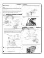
6.Install the removed exteriors in the reverse order of removal.
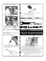
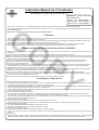
2.Arrow of the switch indicates a setting shown by numbers or letter.
CAUTION : Be careful NOT to pinch the wire harness in FI controller.
7.Referring to the “Recommended settings for the specified models or specs” in this page, adjust the FI controller switch at the designated setting No. which matches your engine specifications. Then, attach the
supplied rubber cap onto the switch panel.
CAUTION : Attach the rubber cap securely. If the rubber is wrongly fit on
the switch, there will be a gap between the rubber cap and
the panel of the FI controller. This may cause the rubber cap
When it shows “0”, the amount of fuel injection is almost the same as the
amount injected by the genuine ECU.(No fuel increase)
The amount of fuel injection increases more than the amount injected by
the genuine ECU following to the numbers and letters of the dial from “1”
to “F” by turning it clockwise.
3.The adjustment is a 16-step adjustment type starting from 0. Be sure to set at a figure or letter precisely until it clicks into place. (If the clicks are
incomplete, the controller does not work properly.)
to fall off or let the dust or water get into the FI controller through the gap, which may ultimately lead to the
breakdown of the FI controller.
4.When the green LED is on, this indicates that FI controller is powered.
When the FI controller is operating properly, the green LED lights up.
(The ignition switch must be “ON”.)
5.When the ignition switch is turned on, the self-diagnosis function starts
operating and the red LED lights up for one second.
However, if the red LED does not light up at all or, on the contrary, remains on, turn off the ignition switch. Please try to turn on the ignition
switch again ten seconds later.
6.Moreover, the red LED is designed to light up as a warning light when CO
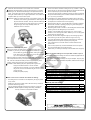
●About the rubber cap and panel:
over burdening on the fuel injector while the engine is running.
If you open the throttle quickly when the engine is still cool, there is a possibility that the fuel injector may keep on injecting fuel.
This is because the FI controller works to further extend the fuel
injection time.
This kind of symptom may cause the breakdown of the fuel injector. Thus, the red LED lights up as a warning light.
Please drive your motorcycle carefully so the red LED does not light up.
PY
・Remove the rubber cap ONLY when you adjust the rotary switch.
CAUTION : If you drive your motorcycle without the rubber cap on, the dust or water may get into FI controller, causing it to break down. When riding, be sure to cover the top with the rubber ●Recommended settings for the specified models or specs
・The following table of the settings are all for the vehicles equipped with our
cap or the transparent panel in the kit.
・When the setting is finished, peel off the panel stuck on the switch at the S-Stage Kit and our Hyper Camshaft.
time of shipment from factory, and replace the panel with the transparent ・Note : These recommended settings are only the samples. They may vary
one. And this increases the dust-proof and drip-proof quality of the with external factors such as ambient temperature, altitude or rider’s weight.
product, leading to the prevention of the needless troubles.
CAUTION : When attaching the panel, please paste it right on the
octagonal recessed surface on the FI controller.
If the panel is fit on the edge, not on the recessed surface or
the groove, then the dust or water will get into the controller
through the gap.
Please place panel properly.
●How to use the FI controller and about the setting:
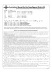
■Monkey (FI)
Engine specifications
Stock air cleaner box + stock exhaust system
Stock air cleaner box + TAKEGAWA Z-style exhaust system
Stock air cleaner box + TAKEGAWA Basic exhaust system
TAKEGAWA Air Filter Kit + stock exhaust system
TAKEGAWA Air Filter Kit + TAKEGAWA Z-style exhaust system
TAKEGAWA Air Filter Kit + TAKEGAWA Basic exhaust system
Setting
8
9
8
7
B
B
1.The setting of the FI controller can be adjusted by turning the yellow rotary switch.
Please turn the switch carefully with a flat extra-fine tip crewdriver
(DO NOT deform the grooves).
You can adjust the settings even when the engine is running idle.
WARNING : NEVER adjust the settings while riding. Otherwise, this may cause the consequential accidents.
■Cub (FI) and Little Cub (FI)
Engine specifications
Setting
Stock air cleaner box + Stock exhaust system
7
Stock air cleaner box + TAKEGAWA Bomber exhaust system
C
TAKEGAWA Air Filter Kit + Stock exhaust system
9
TAKEGAWA Air Filter Kit + TAKEGAWA Bomber exhaust system
F
Co.,Ltd.
3-5-16 Nishikiorihigashi Tondabayashi Osaka Japan
TEL : 81-721-25-1357 FAX : 81-721-24-5059 URL : http://www.takegawa.co.jp
-5-
Jul./20/’
10