1
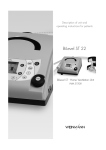
Service and
Repair Instructions
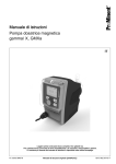
VENTImotion
BiLevel-ST Home Ventilation Unit
WM 24800
VENTIlogic
BiLevel-ST Home Ventilation Unit
WM 27000
Contents
Introduction . . . . . . . . . . . . . . . . . . . . . . . . . . . 3
5.6 Disposal . . . . . . . . . . . . . . . . . . . . . . . 27
1. Overview . . . . . . . . . . . . . . . . . . . . . . . . . . . . . 4
6. Malfunctions and rectification . . . . . . . . . . . . . 28
6.1 General faults. . . . . . . . . . . . . . . . . . . . 28
6.2 Internal faults . . . . . . . . . . . . . . . . . . . . 29
– Fault output in clear text
– Coded error messages
2. Description of device . . . . . . . . . . . . . . . . . . . . 10
2.1 Intended use for VENTImotion/VENTIlogic . 10
2.2 Functional description . . . . . . . . . . . . . . . 10
– Provision of therapy pressure
– Therapy modes
– Other functions
3. Hygiene treatment . . . . . . . . . . . . . . . . . . . . . 11
3.1 Cleaning and disinfecting in use . . . . . . . . 11
3.2 Cleaning and disinfecting on repair . . . . . 11
3.3 Cleaning and disinfecting for a
patient change . . . . . . . . . . . . . . . . . . . 11
3.4 Clean and disinfect humidifier during use . . 12
3.5 Clean and disinfect humidifier on patient
change . . . . . . . . . . . . . . . . . . . . . . . . 12
3.6 Clean and disinfect the VENTIpower . . . . . 12
3.7 Clean and disinfect the VENTI-O2 . . . . . . . 12
4. Test the device . . . . . . . . . . . . . . . . . . . . . . . . 13
4.1 General . . . . . . . . . . . . . . . . . . . . . . . . 13
4.2 Test equipment . . . . . . . . . . . . . . . . . . . 13
4.3 Preparation for testing . . . . . . . . . . . . . . . 13
– Check power supply cable
– Check housing
– Connection to VENTIsupport
4.4 Enter device data . . . . . . . . . . . . . . . . . 14
4.5 Test temperature calibration and
calibration status . . . . . . . . . . . . . . . . . . 14
4.6 Test battery voltage . . . . . . . . . . . . . . . . 15
4.7 Test interface with the VENTIclick . . . . . . . 15
4.8 Check target pressure values
5, 20 and 35 hPa . . . . . . . . . . . . . . . . . 15
4.9 Test flow measurement . . . . . . . . . . . . . . 16
4.10 Test leaktightness . . . . . . . . . . . . . . . . . 17
4.11 Test clock function . . . . . . . . . . . . . . . . . 17
4.12 Test the interface with the VENTI-O2 . . . . . 18
4.13 Test interface with the VENTIpower . . . . . 18
4.14 Test noise . . . . . . . . . . . . . . . . . . . . . . 19
4.15 Test all keys, the rotary knob and
115 V mode . . . . . . . . . . . . . . . . . . . . 19
4.16 Test display incl. backlighting and
contrast, the LEDs and the alarm . . . . . . . 20
4.17 Test equipment and accessories
(system components) . . . . . . . . . . . . . . . 21
– Check function of humidifier
– Function check VENTI-O2
4.18 Once tests are complete. . . . . . . . . . . . . 22
5. Maintenance . . . . . . . . . . . . . . . . . . . . . . . . . 23
5.1 Intervals . . . . . . . . . . . . . . . . . . . . . . . . 23
5.2 Filter change . . . . . . . . . . . . . . . . . . . . . 24
– Coarse dust filter
– Fine filter
– Reset filter change indicator
– Bacteria filter
5.3 Device cleaning . . . . . . . . . . . . . . . . . . 25
5.4 Reset maintenance symbol . . . . . . . . . . . . 26
5.5 Check the maintenance sticker . . . . . . . . . 27
7. Repairguide for VENTImotion/VENTIlogic . . . . 31
7.1 General . . . . . . . . . . . . . . . . . . . . . . . 31
7.2 Open device . . . . . . . . . . . . . . . . . . . . 31
7.3 Close the device . . . . . . . . . . . . . . . . . . 32
7.4 Replace mains supply unit. . . . . . . . . . . . 33
7.5 Replace power board . . . . . . . . . . . . . . 34
7.6 Replace box and filter holder. . . . . . . . . . 35
7.7 Replace fan . . . . . . . . . . . . . . . . . . . . . 37
7.8 Replace control board/display . . . . . . . . 39
7.9 Replace battery on control board . . . . . . . 42
7.10 Dismantle device outlet . . . . . . . . . . . . . 42
7.11 Replace encoder (dial) . . . . . . . . . . . . . 44
7.12 Replace fascia film . . . . . . . . . . . . . . . . 45
7.13 Replace bottom part of housing. . . . . . . . 46
7.14 Replace top part of housing . . . . . . . . . . 47
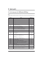
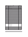
8. Spare parts . . . . . . . . . . . . . . . . . . . . . . . . . . 48
8.1 List of spare parts for
VENTImotion/VENTIlogic . . . . . . . . . . . . 48
8.2 Spare parts required for servicing. . . . . . . 51
9. Tools, test equipment and disinfectants . . . . . . 53
9.1 Tools . . . . . . . . . . . . . . . . . . . . . . . . . 53
9.2 Test equipment and fixtures . . . . . . . . . . . 53
9.3 Disinfectants . . . . . . . . . . . . . . . . . . . . . 54
10. Technical data . . . . . . . . . . . . . . . . . . . . . . . . 55
10.1 Diagram of pneumatic system . . . . . . . . . 57
10.2 Safety distances . . . . . . . . . . . . . . . . . . 57
11. Technical amendments . . . . . . . . . . . . . . . . . . 58
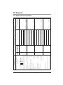
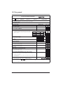
12. Protocols . . . . . . . . . . . . . . . . . . . . . . . . . . . . 59
12.1 Repair and service protocol . . . . . . . . . . 59
12.2 Test protocol . . . . . . . . . . . . . . . . . . . . 60
Introduction
The objective of this service and repair guide is to
familiarize you, an expert, trained specialist, with the
VENTImotion and VENTIlogic in terms of function,
technology, servicing and repair. This will enable
you to train your customers properly, eliminate
faults yourself, perform the function checks specified
by the operating instructions and carry out any repairs in accordance with this service and repair
guide.
In the event of a claim under warranty, return the
devices to Weinmann.
To allow warranty or goodwill applications to be
processed, please also send the final customer's
proof of purchase (invoice).
Repairs may be performed only by Weinmann or
by expert, trained specialists.
You are responsible for repairs carried out yourself
and for their warranty!
Use only original Weinmann spare parts for repair.
Remember:
your customer trusts you and is relying on your ability to do the job, just as you rely on Weinmann.
Note
The following information can be found in the operating instructions for the devices:
•
safety rules
•
setting up device
•
operation
•
cleaning and disinfecting in use
•
warranty
Introduction
3
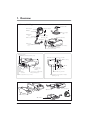
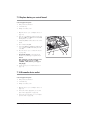
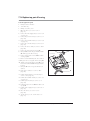
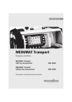
1. Overview
VENTImotion/VENTIlogic
1 Bacteria filter
9 Drying adapter
15 Headgear
14 Mask
2 Power supply
cable
13 Exhalation
system
8 Sealing plugs (2x)
7 Device outlet
12 Hose system
3 Handle
10 Adapter
11 Pressure
measurement
hose
4 Serial interfaces
5 Control panel and displays
6 Connection for humidifier
71 Service label
72 Safety test label (Germany only)
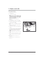
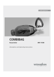
21 Alarm acknowledgement key with LED
22 On/off key
23 Dial
20 Connection for
O2supply valve
VENTI-O2
18 Cable securing
clip
17 Supply
connection
24 Operating keys
25 Menu key
19 Connection for rechargeable
battery VENTIpower
16 Filter compartment cover, air inlet
26 Humidifier key with LED
27 Softstart key/manual start of analysis
(VENTIlogic only)
30 VENTIclick
29 Rating plate
28 VENTIpower
32 VENTI-O2
4
Overview
31 Carrying bag
1 Bacteria filter
To protect the device from contamination, especially if the device is being used by
several patients.
2 Power supply cable
For connecting the therapy device to the mains power supply.
3 Handle
For transporting the device.
4 Serial interfaces
For connecting to devices, for display, evaluation.
5 Control panel and displays
For controlling and monitoring the therapy device and the connected accessories.
6 Connection for humidifier
For connecting the VENTIclick humidifier available as an accessory.
7 Device outlet
Respiratory air flows out from here to the patient via the hose system and nasal mask.
8 Sealing plugs (2x)
For sealing the pressure measurement hose during cleaning.
9 Drying adapter
Required to dry the hose system with the therapy device and for function check.
10 Adapter
For connecting the hose system to the device outlet.
11 Pressure measurement hose
For measuring the pressure prevailing in the mask.
12 Hose system
The air flows to the mask through the hose system. The hose system consists of creased
hose, pressure measurement hose and adapter.
13 Exhalation system
Carbondioxide-enriched expired air escapes here during therapy.
14 Mask
Respiratory air at the necessary therapy pressure is administered to the patient via the
mask.
15 Headgear
For correct and secure positioning of the mask.
16 Filter compartment cover, air inlet
For covering and securely positioning the coarse and fine dust filter.
17 Supply connection
This is where the power supply cable is attached to the device.
18 Cable securing clip
Prevents the device being disconnected from the power supply inadvertently.
19 Connection for rechargeable battery VENTIpower
For connecting the VENTIpower mobile power supply available as an accessory.
20 Connection for O2supply valve VENTI-O2
For connecting the VENTI-O2 oxygen supply valve available as an accessory.
21 Alarm acknowledgement key with LED
The alarm acknowledgement key is for temporarily muting alarms. The LED provides a
visual display of alarms.
22 On/off key
For switching the therapy device on and off.
23 Dial
Central control of the therapy device, for navigating in the menu.
Overview
5
24 Operating keys
For rapid setting by a physician, disabled in patient mode.
25 Menu key
For switching to and fro between the standard display and the menu.
26 Humidifier key with LED
For switching the humidifier on and off or for setting humidifier stage. Six levels are
available. The LED indicates whether the humidifier is activated.
27 Softstart key/manual start of analysis (VENTIlogic only)
For activating Softstart and for setting Softstart time up to the maximum Softstart time set
in the menu.
In TA mode (VENTIlogic only), this key is used to start an analysis phase manually.
28 VENTIpower
Available as an accessory to provide a mobile power source for the therapy device.
29 Rating plate
Provides information about the device, such as serial number and year of manufacture.
30 VENTIclick
Available as an accessory for humidifying and heating respiratory air.
31 Carrying bag
For transporting the therapy device.
32 VENTI-O2
Available as an accessory, for introducing oxygen to the mask.
71 Service label
Indicates when maintenance is next due.
72 Safety test label (in Germany only)
Indicates when the next safety check in accordance with §6 of the German law relating
to owners of medical devices [Medizinprodukte-Betreiberverordnung] is due.
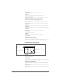
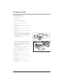
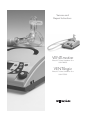
Standard display during therapy
1 Status line
2 Padlock symbol
7 Active ventilation
mode
3 Respiratory phase switch
indicator
6 Ventilation parameters
4 Access to menu
5 Bar chart for pressure indicator
1 Status line
This is where information about the status of the device is displayed, such as filter
change or maintenance due.
2 Padlock symbol
Indicates whether physician functions are enabled (padlock open) or disabled (padlock
closed). The padlock is not displayed in patient mode.
3 Respiratory phase switch indicator
Indicates whether the current respiratory phase switch is spontaneous or mandatory
(spontaneous: S, mandatory: T); the indicator switches from left (inspiration) to right
(exhalation) depending on respiratory phase; spontaneous exspiration is shown here.
4 Access to menu
The key next to this menu item is used to switch to and fro between the menu and the
standard display.
6
Overview
5 Bar chart for pressure indicator
For graphical display of pressure.
6 Ventilation parameters
The relevant current ventilation parameters are displayed depending on the active
mode.
7 Active ventilation mode
The active ventilation mode is displayed at this point in the status line.
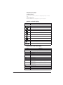
Symbols used in the display
Symbol
Significance
Status line:
Softstart active, remaining time faded in
Filter change required
Maintenance required
Acoustic signal for the IPAPmin and VTmin alarms mute
Alarm for IPAPmin and VTmin alarms deactivated
Physician functions enabled
Physician functions disabled
Fan off (with VENTImotion, only available from software version 6.0)
Main window
Low-priority alarm triggered
Medium-priority alarm triggered
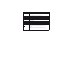
Abbreviations used in the display
Symbol
Significance
Status line:
TA
TA mode active (VENTIlogic only)
S
S mode active
ST
ST mode active
T
T mode active
SX
SX mode active
SXX
SXX mode active
CPAP
CPAP mode active
+V
Volume compensation activated (follows mode: e.g. SXX+V)
AA
Device in TA mode, automatic analysis phase in progress
(VENTIlogic only)
AM
Device in TA mode, manual analysis phase in progress
(VENTIlogic only)
Main window (monitor)
IPAP
Inspiration pressure
EPAP
Expiration pressure
hPa
Pressure shown in hectopascal; 1.01973 hPa correspond to 1 cm H2O
Overview
7
Symbol
Significance
f
Respiratory frequency
S
Spontaneously-triggered respiratory phase switch
T
Compulsorily-triggered respiratory phase switch
Main window ("Statistics" menu item):
8
Overview
Δp
Maximum rise in pressure due to volume compensation
V
Volume
MV
Per minute volume
Leak
System leak (mask, exspiration system, hose system, device)
f
Respiratory frequency
Ti/T
Proportion of inspiration time in a respiratory cycle
Sins
Proportion of spontaneous inspiration (only when mean values
displayed)
Sexs
Proportion of spontaneous exspiration (only when mean values
displayed)
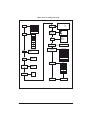
Menu structure in Physician mode
Statistics
Actual values
Target values
Means
In SX mode:
In SXX mode
• TTi
• TTi
• TTi
• TTi
• TTe
Appliance usage
TA statistics
(VENTIlogic only)
Mode
TA setting
(VENTIlogic only)
Values to be set:
e
TA mode
(VENTIlogic
only)
S mode
T mode
Softstart
ST mode
• Lock on/off
• Tmax
• IPAP start
• EPAP start
SX mode
SXX mode
Patient mode
Activate patient mode
CPAP mode
Alarms
• On/Off/Sound off
• IPAPmin
• Vtmin
Device
configuration
Set date/time
Reset filter change counter
Reset maintenance counter
Reset device usage
Triggers
Reset therapy values
• Inspiration
• Expiration
Reset operating time
Language
Pressure rise
German
English
• Inspiration
• Expiration
French
Italian
Volume comp.
Norwegian
• On/Off
• VT
•
p
Back
Back to monitor
Overview
9
2. Description of device
2.1 Intended use for VENTImotion/VENTIlogic
VENTImotion and VENTIlogic are home ventilation
devices for the non-invasive, non-life support ventilation of adult patients with respiratory insufficiency
in whom there is evidence of autonomous respiratory drive. This corresponds to the following clinical pictures:
•
disorders of the respiratory mechanism like
scoliosis, deformity of the thorax
•
neurological, muscular and neuromuscular disorders
•
central respiratory regulation disorders
•
VENTImotion and VENTIlogic are not suitable for
restrictive and obstructive ventilation disorders
like paresis of the diaphragm, OSAS, COPD
life-support use.
Use the device only for the purpose described
here.
2.2 Functional description
Provision of therapy pressure
An electronically-controlled fan draws in ambient
air through a filter and delivers it to the device outlet. From here, the air flows through the hose system and the mask to the patient.
Sensors detect the pressure in the mask and in the
hose system and also the respiratory phase switch
(trigger point). The fan accordingly provides the
IPAP and EPAP pressures set by the doctor.
Therapy modes
The device can be operated in the following therapy modes: CPAP, S, ST, T, SX, SXX, TA (TA with
VENTIlogic only).
In time-controlled mode T and in assisted-controlled
mode ST, your doctor can set respiratory frequency
in the range from 6 to 45 breaths per minute and
inspiration time in the range from 20 % to 67 % of
the respiratory period.
In assisted modes S, SX and SXX and in assistedcontrolled mode ST, your doctor can select one of
6 trigger levels for both inspiration and exhalation.
Your doctor can switch off the trigger for exhalation. Exhalation is then time-controlled.
In the adaptive, controlled TA mode, the device
automatically adapts to your personal breathing
rhythm and supplies the therapy pressure in exactly
the same rhythm.
If no breath is taken into the device in S mode,
pressure is switched at a minimum frequency of
6 breaths per minute.
You can activate volume compensation. Minimum
volume and maximum pressure rise are set for this
purpose. If the minimum volume is undershot, the
device automatically increases pressure continuously until the set maximum pressure (therapy pressure + max. pressure rise) is reached.
Other functions
The Softstart function makes it easier to fall asleep.
Your doctor sets initial pressures for inspiration and
exhalation which continuously rise to the therapy
pressures during the Softstart phase. This function
can be disabled by the doctor.
The therapy device has an auto switch-on system.
If this is activated, the device can be switched on
10
Description of device
by a breath being taken into the mask. The device
is still switched off using the on/off key
.
The display shows therapy mode and, depending
on mode, the values currently being applied for
CPAP/IPAP and EPAP and for respiratory frequency (f). Spontaneous or mechanical respiratory
phase switches are also displayed and the pressure change shown in the form of a graph.
3. Hygiene treatment
3.1 Cleaning and disinfecting in use
Caution!
This item is described in section “5. Hygienic treatment” of the therapy device operating instructions.
There follows a description of the hygiene treatment of the device in the event of repair and in the event of
a patient change.
3.2 Cleaning and disinfecting on repair
A dealer should perform the following during a repair!
Caution!
It is essential to follow the instructions issued by the
manufacturer of the disinfectant (9.3, page 54). It
is recommended that you use suitable gloves for
disinfecting (e.g. household rubber gloves or disposable gloves).
•
Clean hose, headgear and nasal mask in accordance with the operating instructions or replace with new parts (depending on condition).
•
Open device as per item 7.2.
•
Replace filters (coarse dust and fine filter).
•
•
Clean out the inside of device housing and
filter housing using a vacuum cleaner, clean
extremely soiled areas.
•
Close device as per item 7.3.
Wipe down outer housing and power supply
cable with TERRALIN.
3.3 Cleaning and disinfecting for a patient change
If the device is to be hygiene-treated for another patient, perform the following steps.
Caution!
•
Replace coarse and fine dust filters 39 + 40.
It is essential to follow the instructions issued by the
manufacturer of the disinfectant (9.3, page 54). It
is recommended that you use suitable gloves for
disinfecting (e.g. household rubber gloves or disposable gloves).
•
Open box 58 as per section 7.7.
•
Spray-disinfect box, lid, fan, fan flap, motor
bearing, fan cable, filter holder 37 and filter
compartment cover 16 twice with MIKROZID
LIQUID, in each case waiting the prescribed
time for the product to take effect. In addition,
at the start of the time for the product to take
effect, wipe down accessible areas with a
cloth wetted in MIKROZID LIQUID.
•
Replace the following parts with new parts:
•
Wipe down outer housing and power supply
cable with TERRALIN. Dispose of hose and
mask system, headgear, exhalation system
and carrying bag WM 24888 and replace
with new parts.
•
Open device as per section 7.2.
•
Clean out the inside of the device housing,
box and filter holder using a vacuum cleaner,
clean extremely soiled areas.
– hose system WM 24130
– filters WM 24870 and WM 24880
– pressure and flow measurement hoses
WM 24324, WM 24835
– hose, pressure side WM 24852
Hygiene treatment
11
–
–
–
–
–
–
–
–
–
–
–
device outlet, complete, WM 24025
labyrinths WM 24897
decoupling tube WM 24028
motor frame WM 24898
cushioning insert, box WM 24874
fan box gasket WM 24868
filter holder gasket WM 24151
hose, intake side WM 24809
foam for expansion space WM 24171
foam for filter holder WM 24155
countersunk screw ISO 7045-M4x6V2A-H with Tuflok
•
Insert device outlet WM 24025
•
Replacing the WM 24837 control board
Note: This is necessary because the flow sensor located on the control board cannot be
sterilised.
•
Close device as per item 7.3, disinfect outer
housing and power supply cable with
TERRALIN wipes.
•
Reset maintenance symbol to set the maintenance indicator to "0" (see "5.4 Reset maintenance symbol" on page 26).
•
Seal box 58 again as per section 7.7.
•
Test the device.
•
Alternatively, the box 58 can be replaced by
a reconditioned box as described in section
"7.6 Replace box and filter holder" on
page 35.
•
Delete patient data stored in the device as
described in the hospital manual for the
VENTImotion.
3.4 Clean and disinfect humidifier during use
This item is described in section "4. Hygiene treatment" in the VENTIclick operating instructions.
3.5 Clean and disinfect humidifier on patient change
If the device is to be hygiene-treated for another patient, perform the following steps.
•
For hygiene reasons we recommend replacing
plastic parts after a maximum period of use of
2 years. The spare parts list can be found in
the operating instructions for the VENTIclick.
•
If plastic parts and the heating element are
heavily soiled or coated in limescale, offer a
new device, otherwise:
proceed in accordance with section "4. Hygiene treatment" in the operating instructions
for VENTIclick.
3.6 Clean and disinfect the VENTIpower
This item is described in section "4. Hygiene treatment" in the VENTIpower operating instructions.
3.7 Clean and disinfect the VENTI-O2
This item is described in section "4. Hygiene treatment" in the VENTI-O2 operating instructions.
12
Hygiene treatment
4. Test the device
4.1 General
Important!
The device must be subjected to the following test following every repair, maintenance and hygienic treatment in accordance with test instruction WM 24827
and the test protocol. The test can also be used to
assist during troubleshooting.
For the therapy device, enter the operating hours
and all parameters in your service protocol (see
page 59).
If you find faults or deviations from target values
during the test, you must not use the therapy device
again until the faults are eliminated.
The possible causes of the faults and how you eliminate malfunctions can be found in section "6. Malfunctions and rectification" on page 28.
4.2 Test equipment
•
Flow measurement device
•
Test set WM 23465 incl. 23635 pressure measurement adapter
•
PC and PC software VENTIsupport
•
Converter box WM 93316
•
Connecting cables WM 93312 and WM 96313
•
115 V power source, e.g. travel adapter 230 V/115 V, 200 W
•
Test protocol (see "12.2 Test protocol" on page 60)
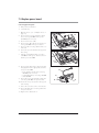
4.3 Preparation for testing
Check power supply cable
1. Check the power supply cable 2.
Ensure that
– the insulation is OK,
– the cable is undamaged
– and there are no loose contacts.
2. Replace the power supply cable 2 if necessary.
Check housing
Check the housing for general condition.
– If the housing is damaged or defective, replace the relevant side of the device (see
"7.13 Replace bottom part of housing" on
page 46/"7.14 Replace top part of housing" on page 47).
Test the device
13
Connection to VENTIsupport
1. Plug the plug of the power supply cable into a socket.
2. Have the test protocol to hand.
3. Connect the serial interface of the therapy device to the PC via the converter box.
4. Start the VENTIsupport program.
5. Click on the VENTIadjust item in the menu bar.
6. Note the set therapy parameters.
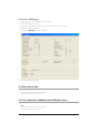
4.4 Enter device data
•
Enter the type, number and date of manufacture of the device in the test protocol.
4.5 Test temperature calibration and calibration status
Note
This test is not needed, as it can only be performed on a Weinmann test bench.
14
Test the device
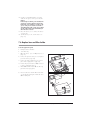
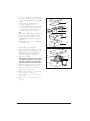
4.6 Test battery voltage
1. Plug the red drying adapter into the device outlet of the VENTImotion.
2. Turn on the device.
Requirement: if battery voltage is sufficient, no
maintenance symbol should appear in the display.
3. Replace
4. Turn off the device.
Note
If battery voltage is inadequate, replace the
battery on the control board (see "7.9 Replace battery on control board" on page 42).
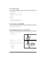
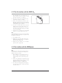
4.7 Test interface with the VENTIclick
•
Check the function of the humidifier (see "
Check function of humidifier" on page 21).
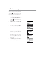
4.8 Check target pressure values 5, 20 and 35 hPa
1. Connect the hose system and the mask to the
therapy device.
2. Pull a plug off the mask.
Plug
3. Connect a pressure meter to the opened
connector.
4. Turn on the device.
5. Prepare the therapy device for testing by making the following settings in the “Physician”
menu:
–
–
–
–
–
T mode
Frequency f = 6/min
Ti:T = 50 %
EPAP 5 hPA
IPAP 35 hPA
Test the device
15
6. Read off the pressure displayed by the measurement device and enter it on the protocol in
the “Measuring result” column.
7. Read off the actual pressure displayed by the
therapy device and enter it on the protocol in
the “Mask” column.
8. Change the setting from EPAP 5 hPA to EPAP
20 hPA.
9. Read off the pressure displayed by the measurement device and enter it on the protocol in
the “Measuring result” column.
10. Read off the actual pressure displayed by the
therapy device and enter it on the protocol in
the “Mask” column.
11. Turn off the device.
Requirement: the values must be within the toleranc-
es quoted in the protocol.
Note
If the values are not within the quoted tolerances,
replace the control board (see "7.8 Replace control board/display" on page 39).
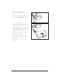
4.9 Test flow measurement
1. Connect the device output of the therapy device to the flow measurement device using the
short hose.
2. Turn on the device.
3. Prepare the VENTImotion for testing by making
the following settings in the "Physician" menu:
– T mode
– frequency f = 6/min
– Ti:T = 50 %
4. Set the two pressures so that the device displays 50 and 100 l/min in the flow window.
For example: IPAP=10 hPa and EPAP=5 hPa
Call up the flow window by pressing the rotary
knob in the "Physician" menu during operation
and selecting “Flow curve” in the Display
menu.
Correct the entry for pressures if necessary.
5. Enter the values displayed by the flow measurement device in the protocol.
Requirement: the values must be within the
tolerances quoted in the protocol.
6. Turn off the device.
Note
If the values are outside the tolerances, replace the control board (see "7.8 Replace
control board/display" on page 39).
16
Test the device
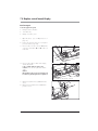
4.10 Test leaktightness
1. Plug the test adapter onto the device outlet.
2. Connect the side connection to the pressure
measurement device.
3. Turn on the device. Select CPAP mode in the
"Physician" menu and set a pressure of
20 hPa.
4. Read off the pressure displayed by the pressure measurement device and enter it in the
protocol.
Requirement: the values must be within the tol-
erances quoted in the protocol.
5. Turn off the device.
Note
If the value is outside tolerance, dismantle the
device (see "7.2 Open device" on page 31)
and check for leaks.
4.11 Test clock function
1. Connect the serial interface of the therapy device to the PC via the converter box.
2. Start the VENTIsupport program.
3. Click on the VENTIadjust item in the menu bar.
4. Select the Set technical data tab.
5. Compare "Device time" and "PC time".
Requirement: the values must change to the
same extent.
Test the device
17
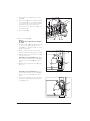
4.12 Test the interface with the VENTI-O2
1. Fit a VENTI-O2 valve to the therapy device so
that it is ready to work. The indicator on top of
the valve housing does not light up.
2. Close the opening of the nasal mask, using
your thumb or hand, for example.
3. Switch on the therapy device first, then your
O2 supply. After the therapy device has been
switched on, the valve opens with a soft "click"
indicated by the green indicator.
4. You can now set the test flow rate on the flow
display of your oxygen system. If this is not
possible, first check the function of your oxygen system (is the cylinder empty, for example,
or are hoses kinked?).
5. Switch the device off again. The valve audibly
switches to "vent", the indicator goes out.
Note
If the VENTI-O2 valve does not react as described,
perform the following measures in sequence and
test again in each case.
•
Use a different valve.
•
Replace the connecting cable of the power
board/mains supply unit (see "7.5 Replace
power board" on page 34).
•
Replace the power board (see "7.5 Replace
power board" on page 34).
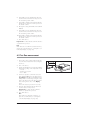
4.13 Test interface with the VENTIpower
Note
Before this test is carried out, the therapy device
must have been connected to the mains power
supply for at least 5 minutes.
1. Fit the VENTIpower to the therapy device so
that it is ready to work therapy device. Connect the therapy device to the mains power
supply.
2. Switch on the VENTIpower and then the therapy device. VENTIpower is working correctly if
its displays go out, in other words, if
VENTIpower switches to standby mode.
3. Now disconnect the plug of the therapy device, the device switches off. The power failure alarm sounds.
18
Test the device
Indicator
VENTIpower is working correctly if its displays
comes on after approx. 4 seconds and the
therapy device starts working again.
4. Now restore the mains power supply to the
therapy device. VENTIpower is working correctly if its displays go out, in other words, if
VENTIpower switches to standby mode.
5. Switch off both devices.
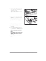
4.14 Test noise
Note
This test is not needed, as it can only be performed
on a Weinmann test bench.
4.15 Test all keys, the rotary knob and 115 V mode
1. Plug the red drying adapter into the device
outlet.
2. Connect the device to a 115 V power source
and switch on the device.
Requirement: the device must start working.
3. Press all the keys and the rotary knob to test
their function.
4. Turn off the device.
Note
If the keys do not work properly, perform the following measures in sequence and test again in
each case.
•
Check fascia film and replace if necessary
(see "7.12 Replace fascia film" on page 45).
•
Replace the control board (see "7.8 Replace
control board/display" on page 39).
Note
If the rotary knob does not work properly, perform
the following measures in sequence and test again
in each case:
•
Change the encoder (see "7.11 Replace encoder (dial)" on page 44).
•
Replace the control board (see "7.8 Replace
control board/display" on page 39).
Note
if 115 V mode does not work properly, replace
the mains supply unit (see "7.4 Replace mains supply unit" on page 33).
Test the device
19
4.16 Test display incl. backlighting and contrast, the LEDs and the
alarm
Note
Before this test is carried out, the VENTImotion must
have been connected to the mains power supply
for at least 5 minutes.
1. Switch on the device.
A beep sounds. Both LEDs come on briefly.
2. Check whether the display is easy to read with
backlighting and that contrast is adequate.
Set contrast
1. Disconnect the power supply plug.
2. Press the humidifier key
key
simultaneously.
and the Softstart
3. Connect the power supply plug and the socket
again.
4. Turn the rotary knob to select contrast. Activate
contrast by pressing the rotary knob.
Note
If no beep is heard when you switch on, perform
the following measures in sequence and test again
in each case.
•
Test the buzzer and replace if necessary (see
"7.13 Replace bottom part of housing" on
page 46).
•
Replace the control board (see "7.8 Replace
control board/display" on page 39).
Note
If the contrast cannot be set, perform the following
measures in sequence and test again in each
case.
•
Check the display cable.
•
Replace the display (see "7.8 Replace control
board/display" on page 39).
•
Replace the control board (see "7.8 Replace
control board/display" on page 39).
20
Test the device
4.17 Test equipment and accessories (system components)
•
Humidifier VENTIclick present
•
Hose system present
•
Oxygen supply valve VENTI-O2 present
•
Rechargeable battery VENTIpower present
•
Medical devices manual present (Germany only)
•
Operating instructions present
Check function of humidifier
Important!
It is essential to note the heating level set before carrying out this test.
Caution
Perform this test even if the patient has not used
or will not be using the humidifier.
1. Subject the plastic housing to a visual check:
in the event of cracks/damage and severe
soiling, the plastic parts or gaskets should be
replaced.
2. Fill the humidifier with water up to the mark.
3. Check whether the humidifier is leaktight.
4. Pour out the water.
5. Now pour in 50 ml of water.
6. Click the humidifier onto the therapy device.
7. Plug the red drying adapter (included in the
scope of supply of the therapy device) into the
outlet connector of the humidifier.
8. Plug the hose system onto the drying adapter.
9. Turn on the therapy device.
10. Turn on the humidifier by pressing the humidifier key
on the therapy device.
11. Set heating level 6 on the therapy device.
12. Check whether the humidifier is heating up.
13. Take off the hose system by pushing the
locking button of the adapter.
14. Pull the red drying adapter out of the humidifier
by twisting it slightly.
15. Set the heating level back to the value you
noted.
Note
•
If the humidifier has not heated up, perform the
following measures in sequence and test
again in each case.
•
Replace the humidifier socket and cable (see
"7.13 Replace bottom part of housing" on
page 46).
Use a different humidifier. Is the heating element OK?
•
Replace the power board (see "7.5 Replace
power board" on page 34).
Test the device
21
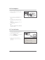
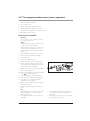
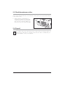
Function check VENTI-O2
1. Fit the VENTI-O2 to the therapy device so that
it is ready to work. The status display on top of
the valve housing does not light up.
2. Attach the test hose supplied (length approx.
48 cm) to the O2 outlet ( ).
3. First switch on your therapy device and then
your O2 supply. After the therapy device has
been switched on, the valve opens with a soft
"click". The green status display lights up.
4. Close the opening of the mask, using a thumb
or hand, for example.
5. Set the prescribed flow rate at the flow setting
of your oxygen system. If this is not possible,
first check the function of your oxygen system
(is the cylinder empty, for example, or are
hoses kinked?).
6. Hold the free end of the test hose in a glass
half-filled with water. VENTI-O2 is working correctly if bubbles escape from the end of the
hose.
7. Switch the therapy device off again.
VENTI-O2 is working correctly if the valve audibly switches to "vent", the status display goes
out and no more bubbles escape from the end
of the test hose.
8. Shut off the oxygen supply of your oxygen
system.
4.18 Once tests are complete
•
22
Reset the therapy values you noted during preparations.
Test the device
Status display
O2
outlet
5. Maintenance
5.1 Intervals
Both filters 39 and 40 must be regularly checked for soiling.
•
Coarse dust filter 39 needs to be changed every 6 months.
•
Fine filter 40 should be changed after no more
than 1000 operating hours (filter change symbol
appears in the display).
For reasons of hygiene, we recommend replacing the following parts at the intervals stated:
•
pressure measurement hose 11 every 6
months or sooner if soiled.
•
complete mask system every 6 to 12 months
depending on soiling
•
exhalation system in accordance with the relevant operating instructions
See section entitled "Cleaning" in the relevant operating instructions.
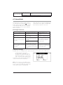
Servicing should be carried out at the following intervals as a preventive measure:
1. after every 5,000 operating hours (maintenance symbol
appears in the display and
should be reset after every service),
2. after no more than 2 years (see service label
on rear of device).
3. after 10,000 hours or 4 years, clean or replace all parts in the air flow.
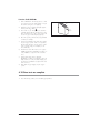
4. Replace service label 71 with one with the
new data (see "8. Spare parts" on page 48).
Cut out the month at a sharp angle using a
punch or nail scissors. Affix the new service label to the left-hand side next to the filter flap.
71
In Germany, a safety control as laid down in §6 of the German law relating to owners of medical devices
[Medizinprodukte-Betreiberverordnung] must also be carried out every 2 years as specified.
Maintenance
23
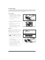
5.2 Filter change
Use only original filters made by Weinmann. If third-party filters are used, this will invalidate the warranty
and may cause restrictions in terms of function and biocompatibility.
Coarse dust filter
1. If the VENTIclick humidifier is connected, first
disconnect it from the device. This will prevent
water running into the device when the filter is
changed. Please also see the operating instructions for the VENTIclick.
2. Press on the latch of the filter compartment
cover and lift it off.
3. Take coarse dust filter 39 out of the filter compartment cover and dispose of it with ordinary
domestic waste.
39
4. Insert clean coarse dust filter 39 in the filter
compartment cover.
5. Insert the filter compartment cover into the
opening in the housing, bottom edge first.
Then push the filter compartment cover into the
housing until the latch engages.
Fine filter
The fine filter needs changing when it has turned
dark in colour, but in any event, after no more than
1000 operating hours. In the latter case, when
VENTImotion is switched on, the message
"Change filter!" appears in the display.
Acknowledge the message by pressing the alarm
acknowledgement key . The filter change symbol
then appears continuously in the status
line. To change the fine filter, proceed as follows:
1. Press on the latch of the filter compartment
cover and lift it off.
2. Take out fine filter 40 and dispose of it with
ordinary domestic waste.
3. Insert a new fine filter 40 WM 15026.
4. Insert the filter compartment cover into the
opening in the housing, bottom edge first.
Then push the filter compartment cover into the
housing until the latch engages.
5. Reset the filter change indicator (see " Reset filter change indicator" on page 25).
24
Maintenance
Filter change indicator
40
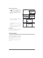
Reset filter change indicator
1. To reset the filter change indicator, press menu
key
with the device switched on and use
the dial to select the item Filter change in the Patient menu or in Physician mode, select the
menu item Device configuration and then Filter
change. Push the dial to call up the "Filter
change" menu.
Patient mode
Physician mode
2. The question "Reset filter change?" appears.
Use the dial to select YES and confirm your selection by pressing the dial.
If you wish to cancel the process, use the dial
to select NO and press the dial. The process is
aborted.
Once you have selected and confirmed YES
with the dial, the message "Filter change reset!" appears for about 3 seconds.
Bacteria filter
If bacteria filter WM 24148 is used, change the
particle filter in the bacteria filter in accordance
with the relevant operating instructions.
5.3 Device cleaning
The parts in the air flow should all be cleaned and
disinfected every 10,000 hours or every 4 years.
This should be performed in accordance with section "3.3 Cleaning and disinfecting for a patient
change" on page 11.
After every maintenance operation, perform a test
according to section "4. Test the device" on
page 13.
Maintenance
25
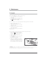
5.4 Reset maintenance symbol
After every service/repair performed, the maintenance indicator must be set to "0", or the maintenance symbol
which has appeared in the
display deleted. In addition, a new service label
(current year +2 years) should be affixed to the
rear of the device.
1. Enable Physician functions. Hold down the
IPAP and EPAP keys for 4 seconds to do so.
The message "This is a physician function!" appears in the display. The display then returns
to Monitor. The status line of the display shows
the symbol
. The Physician functions are
now enabled.
2. In the menu, select the sub-menu Device configuration.
3. Use the dial to select the menu item Maintenance. Confirm your selection by pressing the
dial.
The Maintenance sub-menu is displayed.
If you wish to reset the indicator, use the dial
to position the selection bar on YES. Confirm
your selection by pressing the dial.
4. A display appears in which you are asked
again whether you wish to reset the symbol. If
you are sure, select YES here too and confirm
your selection by pressing the dial. The message: "Maintenance reset!" appears for approx. 2 seconds.
5. To exit the menu, press the menu key (back) until the Monitor is displayed. You can also select
back with the dial and then press the dial.
26
Maintenance
5.5 Check the maintenance sticker
When you have maintained the device, a new maintenance sticker (current year +2 years) must be attached
to the rear of the device.
•
Replace maintenance sticker 71 with one
showing the new data (see "8. Spare parts"
on page 48). Cut out the month using punch
pliers or the tip of a nail cutter. Affix the new
maintenance sticker to the left of the filter flap.
71
5.6 Disposal
Do not dispose of the device with domestic waste. To dispose of the device properly, please contact a licensed, certified electronic scrap disposal merchant. This address is available from your
Environment Officer or from your local authority.
Maintenance
27
6. Malfunctions and rectification
6.1 General faults
Malfunction
Cause
No power supply.
No running noise, standby
and operating displays do
not light up.
Faulty displays or none at all
Rectification
Check connection of power supply cable in device socket.
Check mains voltage with another device, if necessary (for example a
lamp), replace power supply cable if necessary.
Mains supply unit defective. Replace mains supply unit (7.4, page 33).
Cable come loose or
defective.
Check all cable connections in the device; replace if necessary.
Control board defective.
Replace control board (7.8, page 39).
Power board defective.
Replace power board (7.5, page 34). Send defective board to the
manufacturer for fault analysis.
Display defective.
Replace display (7.8, page 39).
Cable come loose or
defective.
Check all cable connections in the device; replace if necessary.
Control board defective.
Replace control board (7.8, page 39).
Control board defective.
Tolerance of therapy pressures
is > 0.6 hPa after 1 minute. Sensor hoses defective or
soiled.
Replace control board (7.8, page 39).
Check hoses, lay correctly (7.8, page 39).
Activate auto switch-on/switch-off
Automatic system not active
In Automatic mode, device
(see 4.1 of operating instructions).
can not be switched on by
Power board defective.
Replace power board (7.5, page 34).
a breath being taken in.
Control board defective.
Replace control board (7.8, page 39).
Device is running but does
not reach the lower pressure limit set.
Filter change indicator
active.
Maintenance display
active.
Filter soiled.
Change both filters (5.2, page 24).
Nasal mask leaking.
Adjust headgear/headband so that the mask is tight.
Leak in device.
Check if all hoses and gaskets are properly located.
Filter soiled.
Clean/change both filters (5.2, page 24).
Maintenance interval
exceeded.
Perform maintenance.
Internal battery discharged.
No power.
Status display of the
VENTI-O2 lights up intermit- Nasal mask leaking.
tently or not at all.
Hose leaking.
The prescribed O2 flow is
not reached.
Water in humidifier is not
heating up.
Adjust headgear/headband so that the mask is tight or use another mask
if necessary.
Check breathing hose and pressure measurement hose.
O2 supply hoses kinked.
Check all hose connections.
Too high a resistance in the
hose system.
Shorten O2 supply hoses.
Output pressure of oxygen
system too low.
If necessary, use another oxygen system, e.g. OXYMAT 3.
Humidifier defective.
Test with a different humidifier, if device is defective, return humidifier to
the manufacturer.
Power board defective.
Replace power board (7.5, page 34). Send defective board to the
manufacturer for fault analysis.
Power supply cable damaged.
28
Check that plug contact is properly located.
Malfunctions and rectification
Replace power supply cable.
The ribbon cable of the film
Check whether the ribbon cable is correctly connected to the display
Device cannot be switched keypad has slipped out of
board.
the connection.
on using the film keypad.
Fascia film defective.
Replace fascia film (7.12, page 45).
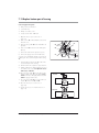
6.2 Internal faults
The therapy device performs a self-test of the sensor system when the on/off switch
is pressed
briefly, checking the function of the alarm. If a fault
occurs during the self-test, an error message appears in the main screen (see also "6.2 Internal
faults" on page 29).
The therapy device can detect internal faults itself
and shows them on the display. The display takes
the form either of clear text or of a code.
Fault output in clear text
Display
Cause
Rectification
"Battery discharged!"
Internal battery of the device is
discharged.
"Clock not set!"
Time not set on device following Set clock as described in
battery change
VENTImotion hospital manual.
Device error; excessive pressure
(Code 32)
Pressure at mask or fan has
exceeded maximum permitted
limit value.
Pressure measurement hose
blocked
Change the battery (7.9,
page 42).
Check ventilation and pressure
measurement hose system for
blockages/leaks.
The temperature on the power
Device error, Upper temperature board has reached a critical
Leave device to cool down and
limit exceeded
value, e.g. as a result of opera- operate it in the permitted ambi(Code 64)
tion in the bag or being in direct ent temperature range.
sunlight.
Coded error messages
For faults which are not displayed with a clear text message, the therapy device issues a fault code.
– A number appears in the first line.
– The appropriate 16-digit fault code appears in the second line. Each of the 16
digits has the value "0" or "1". The position
of the 1 indicates the kind of fault involved.
A description of the cause of the fault and how to
rectify it can be found in the table below.
Position 1
Position 16
Note: several errors may occur simultaneously. In
this case, a "1" will then appear at several points
in the second line. The number in the first line is the
total of all the numbers for individual faults.
Malfunctions and rectification
29
First line:
Second line:
code number 1 at position ...
Cause
Rectification
Replace battery on control board (see section
7.9 on page 42).
1
1
Clock not responding
or
battery discharged
If fault occurs again, replace control board
(see section 7.8 on page 39).
Replace fan or fan box. (see section 7.7 on
page 37).
Replace power board (see section 7.5 on
page 34).
2
EEPROM not responding
Replace control board (see section 7.8 on
page 39).
4
3
Transmitting fault at the
serial connections.
Replace control board (see section 7.8 on
page 39).
If this occurs on final test bench, please
inform QM.
8
4
Sensor measurement has
failed plausibility test.
Replace control board (see section 7.8 on
page 39).
2
Check cable connections between fan,
power board and control board.
Fan has failed or fan not
starting up. Either there is Replace fan or fan box (see section 7.7 on
no 40 V supply or there is page 37).
a defect on the fan.
Replace power board (see section 7.5 on
page 34).
16
5
128
8
Humidifier current is outside permitted values.
Replace power board (see section 7.5 on
page 34).
256
9
EEPROM has failed
checksum test.
Replace control board (see section 7.8 on
page 39).
512
10
Sensor calibration data in Replace control board (see section 7.8 on
EEPROM invalid.
page 39).
11
Check external and internal pressure measPressure sensor measured urement hoses for blockages.
values outside tolerance Replace control board (see section 7.8 on
page 39).
2048
12
There are invalid therapy
parameter values in the
EEPROM.
4096
13
Data inconsistency, possi- Replace battery on control board (see section
bly battery discharged
7.9 on page 42).
8192
14
No communication with
EEPROM.
Replace control board (see section 7.8 on
page 39).
16384
15
Communication with
watchdog failed.
Replace control board (see section 7.8 on
page 39).
32768
16
Software fault
Replace control board (see section 7.8 on
page 39).
1024
30
Malfunctions and rectification
Replace control board (see section 7.8 on
page 39).
If this occurs on final test bench, please
inform QM.
7. Repairguide for VENTImotion/VENTIlogic
7.1 General
Perform repairs on the VENTImotion or VENTIlogic exclusively at an ESD protected work-station!
•
Follow the safety rules in the operating instructions for the therapy device.
•
Perform a function check after every repair
(see "4. Test the device" on page 13).
•
Any handling of the device assumes accurate
knowledge and observance of the operatinginstructions and the service and repair guide.
•
If you replace components or individual parts,
use only original Weinmann parts.
•
Only perform repairs which are described in
this service and repair guide. This is the only
way to guarantee that the therapy device continues to function properly.
•
When ordering the bottom part of the
housing 35, quote the type, year of manufacture and number of the device as well.
•
Ensure that your hands and your work-station
are clean during repair work.
Note
The item numbers listed in the text which follows are identical to the item numbers in the
spare parts list on page 48 and in the overview on page 4.
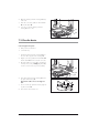
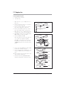
7.2 Open device
Tools and equipment required
•
ESD protected work-station
•
3 mm Allen key
Caution!
Open the device only with the power supply plug disconnected.
1. Place the device on a non-slip surface with the
top facing downwards.
2. Remove the filter cassette from the top part of
the housing.
3. Undo and remove the 6 screws 34.
34
34
Repairguide for VENTImotion/VENTIlogic
31
4. Open the bottom part of the housing 35 away
to the side.
35
5. Undo the connecting cables for the humidifier
42 and the alarm 43.
6. You can now put the bottom part of the
housing 35 to one side.
43
42
7.3 Close the device
Tools and equipment required
•
ESD protected work-station
•
3 mm Allen key
1. Hold the bottom part of the housing 35 up to
the side of the top part of the housing 36.
2. Plug the connecting cables for the humidifier 42
and the alarm 43 onto the relevant connectors.
35
3. Check that all hoses and cables are plugged
on firmly. If necessary, carefully plug these fully
onto the connections (hoses) or slots (cables).
43
42
36
4. Place the bottom part of the housing 35 on the
top part of the housing 36.
Ensure that no cables or hoses are trapped or
bent.
5. Now screw the top part of the housing tight using the 6 screws 34.
6. Then turn the device back over.
32
Repairguide for VENTImotion/VENTIlogic
34
34
7.4 Replace mains supply unit
Tools and equipment required
•
ESD protected work-station
•
3 mm Allen key
1. Open the device (see "7.2 Open device" on
page 31).
2. Disconnect the power board/mains supply
unit connecting cable 45 from the power
board (wide connector).
3. Slightly lift mains supply unit 44 and disconnect
the mains input connector from the mains supply unit 44.
45
44
Mains input
connector
Rechargeable
battery cable
4. Lift the mains supply unit out of the top part of
the housing.
5. Disconnect the power board/mains supply
unit connecting cable from the mains supply
unit and plug into the new mains supply unit.
6. Position the new mains supply unit in the top
part of the housing. Plug the mains input connector onto the new mains supply unit in the
process.
7. Plug the power board/mains supply unit connecting cable 45 onto the power board (wide
connector).
Caution!
Be absolutely sure that power board/mains supply unit connecting cable 45 is between the head
of the screw and the box as well as in the groove
of the power board. Ensure that the rechargeable
battery cable is in the groove. Otherwise the cable may be trapped and damaged when the device is closed.
8. Close the device (see "7.3 Close the device"
on page 32).
9. Test the device (see "4. Test the device" on
page 13).
Repairguide for VENTImotion/VENTIlogic
33
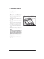
7.5 Replace power board
Tools and equipment required
•
ESD protected work-station
•
3 mm Allen key
1. Open the device (see "7.2 Open device" on
page 31).
Motor cable
70
2. Disconnect the power board/mains supply
unit connecting cable 45 from the power
board 41 (wide connector).
3. Disconnect the motor cable.
4. Disconnect the O2 valve/power board connecting cable 70 from the power board.
45
41
5. Disconnect all connecting cables from the control board.
6. Remove the power board from the top part of
the housing.
7. Take the rechargeable battery connecting
cable 48 out of the groove and disconnect it
from the power board 41.
45
41
48
8. Disconnect the cables of the old power board
and plug them into the appropriate slots of the
new power board 41:
– power board/control board connecting
cable 46 (wide connector)
– rechargeable battery connecting cable 48
– earth cable 47
9. Connect the power board/mains supply unit
connecting cable 45 to the power board.
10. Position the new power board in the top part
of the housing.
11. Restore the connections to the control board.
12. Connect the O2 valve connecting cable to the
new power board.
13. Plug the motor cable back on.
34
Repairguide for VENTImotion/VENTIlogic
48
41
47
46
14. Insert the rechargeable battery connecting
cable into the groove on the power board.
Caution!
Be absolutely sure that the power board/mains
supply unit connecting cable 45 is between the
head of the screw and the box as well as in the
groove of the power board. Ensure that the rechargeable battery cable is in the groove. Otherwise the cable may be trapped and damaged
when the device is closed.
15. Close the device (see "7.3 Close the device"
on page 32).
16. Test the device (see "4. Test the device" on
page 13).
7.6 Replace box and filter holder
Tools and equipment required
•
ESD protected work-station
•
3 mm Allen key
1. Open the device (see "7.2 Open device" on
page 31).
37
2. Remove the power board (see "7.5 Replace
power board" on page 34).
58
3. Remove the mains supply unit (see "7.4 Replace mains supply unit" on page 33).
4. Release the pressure-side hose 74 (connection
to device outlet) from the box.
74
5. Lift box 58 and filter holder 37 out of the top
part of the housing together.
6. Disconnect the box and the filter holder from
one another by undoing the intake-side hose
73 from both parts.
37
73
58
Repairguide for VENTImotion/VENTIlogic
35
7. Dispose of the foam 38 from the expansion
space and replace box 58.
38
or:
Replace the complete filter holder 37.
37
8. If you have not replaced the filter holder, insert
a new piece of foam 38 in the expansion
space.
9. Connect box and filter holder. To do so, insert
the intake-side hose in both parts. The smooth
part of the hose must be inserted in the filter
holder in each case.
10. Insert the box and the filter holder back in the
device (steps 4. to 6. in reverse sequence). To
facilitate assembly of the intake-side hose 73,
apply a little 70 % isopropanol to the circumference.
11. Refit the mains supply unit (see "7.4 Replace
mains supply unit" on page 33).
12. Refit the power board (see "7.5 Replace
power board" on page 34)
13. Close the device (see "7.3 Close the device"
on page 32).
14. Test the device (see "4. Test the device" on
page 13).
36
Repairguide for VENTImotion/VENTIlogic
37
73
58
7.7 Replace fan
Tools and equipment required
•
ESD protected work-station
•
3 mm Allen key
1. Open the device (see "7.2 Open device" on
page 31).
2. Remove the power board (see "7.5 Replace
power board" on page 34).
58
3. Remove the mains supply unit (see "7.4 Replace mains supply unit" on page 33).
4. Remove box and filter holder (see "7.6 Replace box and filter holder" on page 35).
5. Open the box. To do so, lift the lid using a slot
screwdriver. Then remove the lid of the box.
6. Lift fan 63 up and disconnect decoupling tube
66 from the bore of the motor frame.
7. Remove fan 63 from box 58.
If the same patient is going to be using the device, continue the repair from step 15.
If box 58 is to be treated for a new patient or
be subjected to cleaning in the course of the
10,000-hour/4-year service, then proceed as
follows.
66
63
58
8. Remove motor frame 60 and the labyrinths 59
from the box and dispose of them.
9. Remove lid cushioning insert 61 and box cushioning insert 62 from the box and dispose of
them.
10. Clean out the box using a vacuum cleaner and
clean extremely soiled areas.
11. Disinfect the box using MIKROZID LIQUID
(follow the manufacturer's instructionsfor use).
61
59
60
59
62
58
Repairguide for VENTImotion/VENTIlogic
37
12. Insert a new lid cushioning insert 61 and box
cushioning insert 62 as shown, as well as the
two new labyrinths 59 and motor frame 60 in
box 58.
Take care with the assembly position.
61
– Insert the labyrinths as shown.
– Insert motor frame 60 so that the cutout for
the fan cable is flush with the cutout in the
box. Otherwise the fan cable might be
damaged when the box is closed.
59
60
59
13. Tip!
Put motor frame 60 and labyrinths, 59 together
with box cushioning insert 62, in box 58.
Clean the fan and then disinfect it using
MIKROZID LIQUID (follow the manufacturer's
instructions).
62
14. Fit the fan flap with two new screws 68 from
the maintenance kit.
58
15. Insert fan 63 in motor frame 60.
16. Apply a little 70 % isopropanol to the circumference of decoupling tube 66 and fit it in the
appropriate bore of motor frame 60.
The groove of the hose must engage right
round the circumference of the bore.
17. Put the lid on box 58.
Ensure that the lid is fitted in the correct position.
The cable harness of the fan must run through the
cutout in the lid and may not be trapped! The
cable must protrude between 265 and 270 mm.
18. Refit the box and filter holder (see "7.6 Replace box and filter holder" on page 35)
19. Refit the power board (see "7.5 Replace
power board" on page 34).
20. Refit the mains supply unit (see "7.4 Replace
mains supply unit" on page 33).
21. Close the device (see "7.3 Close the device"
on page 32).
22. Test the device (see "4. Test the device" on
page 13).
38
Repairguide for VENTImotion/VENTIlogic
66
59
58
63
59
60
7.8 Replace control board/display
Perform repair
Tools and equipment required
•
ESD protected work-station
•
3 mm Allen key
•
Phillips screwdriver, size 1
1. Open the device (see "7.2 Open device" on
page 31).
2. Remove the power board (see "7.5 Replace
power board" on page 34).
3. Disconnect the encoder connector 82 and the
connectors of interfaces 84 and 85 of the control board.
85
84
82
4. Disconnect the ribbon cable of the display
and the fascia film:
to do so, pull the latch out until you feel
resistance. You can then pull out the ribbon
cable.
Caution!
If the latch has not been opened correctly, the ribbon cable may be damaged when it is pulled out.
Ribbon cable for fascia film
5. Pull flow measurement hoses 56 off the flow
sensor.
6. Pull pressure measurement hoses 57 off the
pressure sensors.
Ribbon cable for
display
70
56
57
Repairguide for VENTImotion/VENTIlogic
39
7. Undo the four screws 51 and remove control
board 50.
51
52
8. Remove spring 54 from the control board and
remove battery 52 (see "7.9 Replace battery
on control board" on page 42). You need the
metal spring for the new control board.
50
If it is unnecessary to replace the display, continue from step 11.
9. Remove display 49.
10. Insert a new display 49.
Caution!
The display may not tilt and must be straight in
the guides.
Display buffer
49 54
11. Insert a new battery 52 in the appropriate holder of the new control board and screw on
spring 54 (see "7.9 Replace battery on control
board" on page 42).
12. Put the control board in the top part of the
housing and attach it with the four screws 51.
56
13. Reattach the pressure measurement hoses 57
to the pressure sensors.
Ensure that you do not switch the hoses: connect
the connection of the flow sensor marked Hi to
the hose connector marked Hi at the device
outlet.
14. Attach the flow measurement hoses 56 to the
flow sensor.
Hi
Lo
57
Ensure that you do not switch the hoses: connect
the connection of the flow sensor marked Lo to
the hose connector marked Lo at the device
outlet.
15. To prevent hoses kinking, position flow measurement hoses 56 and pressure measurement
hoses 57 as shown.
56
57
40
Repairguide for VENTImotion/VENTIlogic
16. Connect the ribbon cable for the fascia film
and the display to the control board again:
– pull the latch upwards.
– push the ribbon cable into the connector.
– press the latch back down.
Ribbon cable for fascia film
Ribbon cable for
display
17. Plug the connectors of the interfaces and the
rotary knob into the appropriate slots of the
control board.
18. Refit the box and filter holder (see "7.6 Replace box and filter holder" on page 35).
85
84
82
19. Refit the power board (see "7.5 Replace
power board" on page 34).
20. Close the device (see "7.3 Close the device"
on page 32).
21. Check contrast and adjust if necessary (see
"4.16 Test display incl. backlighting and contrast, the LEDs and the alarm" on page 20).
22. Reset the date and time, as described in the
VENTImotion/VENTIlogic hospital manual.
Caution!
After changing the control board, always set the
date in the following sequence: 1. YEAR,
2. MONTH, 3. DAY, otherwise you may get a
faulty display.
23. Test the device (see "4. Test the device" on
page 13).
Repairguide for VENTImotion/VENTIlogic
41
7.9 Replace battery on control board
Tools and equipment required
•
ESD protected work-station
•
3 mm Allen key
•
Phillips screwdriver, size 1
1. Open the device (see "7.2 Open device" on
page 31).
2. Undo the screw 53 on the battery holder and
take spring 54 and seal 55 off control board 50.
Put the parts on one side.
3. Take battery 52 out of the holder on the control
board.
4. Put in a fresh battery 52.
5. Insert spring 54 and seal 55 on the battery holder on control board 50 and fit both parts with
screw 53.
6. Close the device (see "7.3 Close the device"
on page 32).
7. Reset the date and time as described in the
VENTImotion/VENTIlogic hospital manual.
Caution!
After changing the control board, always set the
date in the following sequence: 1. YEAR,
2. MONTH, 3. DAY, otherwise you may get a
faulty display.
8. Test the device (see "4. Test the device" on
page 13).
7.10 Dismantle device outlet
Tools and equipment required
•
ESD protected work-station
•
3 mm Allen key
•
Phillips screwdriver, size 1
1. Open the device (see "7.2 Open device" on
page 31).
2. Remove the mains supply unit (see "7.4 Replace mains supply unit" on page 33).
3. Remove the power board (see "7.5 Replace
power board" on page 34).
42
Repairguide for VENTImotion/VENTIlogic
52
54
55
53
4. Remove box and filter holder (see "7.6 Replace box and filter holder" on page 35).
5. Remove the control board (see "7.8 Replace
control board/display" on page 39).
6. Pull the pressure-side hose off device outlet 90.
Dispose of the pressure-side hose (only when
servicing or changing patients).
56
57
90
7. Pull flow measurement hoses off the flow sensor. Dispose of flow measurement hoses 56.
36
8. Pull pressure measurement hoses 57 off the device outlet. Dispose of pressure measurement
hoses.
9. Remove device outlet 90 from the top part of
the housing 36. To do so, lift the tab slightly using a screwdriver and take out the device outlet.
90
36
10. Remove any adhesive residues from the housing.
11. Place a spot of glue on the lock:
Ø ≤ 1 mm; glue WM 14946 (Loctite 4601)
or WM 14952 (Loctite 4031).
12. Fit a new device outlet 90 in the top part of the
housing 36.
90
glued at
certain spots
36
13. Put new pressure measurement hoses 57 on the
relevant connectors of device outlet 90.
14. Put new flow measurement hoses 56 on the relevant connectors of device outlet 90.
15. Refit the control board (see section 7.8 on
page 39)
56
57
90
36
16. Refit the box and filter holder (see section 7.6
on page 35).
17. Refit the power board (see section 7.5 on
page 34).
18. Refit the mains supply unit (see section 7.4 on
page 33).
19. Close the device (see section 7.3 on
page 32).
20. Test the device (see "4. Test the device" on
page 13).
Repairguide for VENTImotion/VENTIlogic
43
7.11 Replace encoder (dial)
Tools and equipment required
•
ESD protected work-station
•
3 mm Allen key
•
11 mm Allen key adapter
Note
If you only want to replace the dialknob, simply
pull this off the spindle of the encoder and replace
it by a new one. To replace the entire encoder,
proceed as described below.
1. Open the device (see section 7.2 on
page 31).
2. Pull dial 83 off the spindle of encoder 82.
3. Unscrew the hexagon nut on the outside of the
top part of the housing 36.
4. Pull the cable of encoder 82 off control board
50.
5. Take the encoder out of the top part of the
housing from the inside.
36
6. Insert the new encoder in the top part of the
housing.
7. Screw the hexagon nut onto the spindle of the
encoder from the outside. Tighten up the nut.
Ensure that the spindle of the encoder turns
easily.
8. Plug the cable of the encoder onto the control
board.
9. Push the dial onto the spindle of the encoder
up to the stop. Check whether the dial turns
easily.
10. Close the device (see section 7.3 on
page 32).
11. Test the device (see "4. Test the device" on
page 13).
44
Repairguide for VENTImotion/VENTIlogic
82
50
Hexagon nut
83
7.12 Replace fascia film
Tools and equipment required
•
ESD protected work-station
•
3 mm Allen key
•
Phillips screwdriver, size 1
•
Knife with a smooth, flat blade
1. Open the device (see section 7.2 on
page 31).
2. Remove the mains supply unit (see section 7.4
on page 33).
3. Remove the power board (see section 7.5 on
page 34).
4. Remove box and filter holder (see section 7.6
on page 35).
5. Remove the control board and the display (see
section 7.8 on page 39). Undo fascia film 33
using a knife-blade and carefully peel it off.
Use a little 70 % isopropanol to degrease this
part of the housing.
36
33
6. Peel the protective film off the inside of the new
fascia film and affix fascia film 33 to this area
of the housing. Ensure that the ribbon cable is
pushed cleanly through the opening in the housing without any kinks.
7. Carefully pull the outer protective film off the
new fascia film using a fingernail.
8. Refit the display and the control board (see
section 7.8 on page 39).
9. Refit the box and filter holder (see section 7.6
on page 35).
10. Refit the power board (see section 7.5 on
page 34).
11. Refit the mains supply unit (see section 7.4 on
page 33).
12. Close the device (see section 7.3 on
page 32).
13. Test the device (see "4. Test the device" on
page 13).
Repairguide for VENTImotion/VENTIlogic
45
7.13 Replace bottom part of housing
Tools and equipment required
•
ESD protected work-station
•
3 mm Allen key
•
Phillips screwdriver, size 1
•
Torque wrench 20 – 120 Ncm
1. Open the device (see section 7.2 on
page 31).
2. Undo screws 87 of the humidifier socket and
the ferrite core.
70
87
3. Pull connecting cable 70 for the humidifier out
upwards.
86
4. Undo screws 86 and remove the alarm (piezo
buzzer).
88
5. Remove the foam for the expansion space.
6. Remove the plug locators for the O2 valve.
You have now dismantled all parts. Now start assembling into the new bottom part of the housing
35.
69
89
7. Insert the plug locators for the O2 valve in the
new bottom part of the housing.
8. Put the foam for the expansion space back in.
9. Refit the alarm (piezo buzzer) and fix it in position with the two screws 86. Tighten the screws
with a torque of 47 Ncm.
10. Put connecting cable 70 into the plug locator
with the radius of the plug side facing downwards. Both webs of the plug must be located
within the plug locator for this.
Correct:
11. Fix connecting cable 70 in position with lock
washer 69 and screws 87 and 88.
12. Close the device (see section 7.3 on
page 32).
13. Test the device (see "4. Test the device" on
page 13).
46
Repairguide for VENTImotion/VENTIlogic
Incorrect:
35
7.14 Replace top part of housing
Tools and equipment required
•
ESD protected work-station
•
3 mm Allen key
•
Phillips screwdriver, size 1
1. Open the device (see section 7.2 on
page 31).
2. Remove the mains supply unit (see section 7.4
on page 33).
3. Remove the power board (see section 7.5 on
page 34).
4. Remove box and filter holder (see section 7.6
on page 35).
5. Remove the control board (see section 7.8 on
page 39).
6. Remove the device outlet (see section 7.10 on
page 42).
7. Remove the lock washers from pins 79.
8. Push pins 79 out of the hinges and take handle
78 off the top part of the housing.
Obe
81
80
Lock washers
9. Remove mains input connector 80 and cable
securing clip 81.
You have now dismantled all parts. Now start assembling into the new top part of the housing 36.
79
10. Take the new top part of the housing 36 in your
hand and insert handle 78 in the top part of the
housing.
11. Push pins 79 into the hinges and fit the lock
washers.
12. Fit the device outlet (see section 7.10 on
page 42).
78
13. Refit the display and the control board (see
section 7.8 on page 39).
14. Refit the box and filter holder (see section 7.6
on page 35).
15. Refit the power board (see section 7.5 on
page 34).
16. Refit mains input connector 80 and cable securing clip 81.
17. Refit the mains supply unit (see section 7.4 on
page 33).
18. Close the device (see section 7.3 on
page 32).
19. Test the device (see "4. Test the device" on
page 13).
Repairguide for VENTImotion/VENTIlogic
47
8. Spare parts
8.1 List of spare parts for VENTImotion/VENTIlogic
Note
The item numbers in the table are identical to the numbers in the text of this service and repair guide. There are
gaps in the numbering because the numbers were assigned in the operating instructions, but not all parts are spare
parts.
Item no.
Article no.
2
Power supply cable
WM 24177
8
Plug for pressure measurement hose
WM 24115
11
Pressure measurement hose
WM 24038
12
Hose system
WM 24130
16
Filter flap
WM 24180
31
Carrying bag
WM 24888
33
Fascia film for VENTImotion
Fascia film for VENTIlogic
WM 24833
WM 27033
34
Cap screw M4 x 12-8.8 ST-ZN
WM 50605
35
Housing, bottom part with nameplate
WM 24887
36
Housing, top part with fascia film, VENTImotion
Housing, top part with fascia film, VENTIlogic
WM 24804
WM 27028
37
Filter holder, complete
WM 24150
38
Foam, expansion space
WM 24171
39
40
Set of spare filters (sufficient for a year)
Coarse dust filter
Fine dust filter
WM 15682
WM 24880
WM 15026
41
48
Name
VENTImotion:
Printed circuit,
Printed circuit,
VENTIlogic:
Printed circuit,
Printed circuit,
power board, new
power board, replacement
WM 24840
WM 24849
power board, new
power board, replacement
WM 27090
WM 27099
42
Connecting cable for humidifier, ferrite core
WM 24254
43
Piezo buzzer/alarm
WM 24109
44
Mains supply unit with insulating board
WM 24213
45
Connecting cable for power board/mains supply unit
WM 24861
46
Connecting cable for power board/control board
WM 24307
47
Cable, earth
WM 24813
48
Rechargeable battery socket with cable (connecting cable
for rechargeable battery socket/power board)
WM 24507
49
LC display
WM 24828
50
Printed circuit, control board, new
Printed circuit, control board, reconditioned
WM 24890
WM 24837
Spare parts
Item no.
Name
Article no.
51
Screw with washer KB 25 x 12 with washer 9-3-3
(for control board)
WM 24812
52
Battery, 3 V
WM 24946
53
Tallow-drop screw M 3 x 6 (for spring to secure battery)
WM 53020
54
Spring for battery
WM 24953
55
Seal
WM 1145/32
56
Connecting hose, silicone 3 x 7, 130 mm long
WM 24835
57
Pressure measurement hose, silicone 2.5 x 1.5, 200 mm
long
WM 24324
58
Fan box, complete, new
Fan box, complete, reconditioned
WM 24832
WM 24838
59
Labyrinth, self-adhesive
WM 24897
60
Motor frame, self-adhesive
WM 24898
61
Cushioning insert, lid (fan box gasket)
WM 24868
62
Cushioning insert, box
WM 24874
63
Fan with bearing
consisting of:
– fan, complete
– motor bearing
– decoupling tube
– threaded pin DIN 916, M4 x 6-V2A
WM 24848
Fan, complete, new
Fan, complete, reconditioned
WM 24834
WM 24839
68
Countersunk screw ISO 7045 M4 x 6 (for fan)
WM 51393
69
Lock washer, humidifier cable
WM 24088
70
Connecting cable for O2valve)
WM 24117
71
Service label *
– for 2007
– for 2008
– for 2009
– for 2010
– for 2011
– for 2012
WM
WM
WM
WM
WM
WM
72
Safety test label *
– for 2007
– for 2008
– for 2009
– for 2010
only for internal
Weinmann use
73
Hose, intake side
WM 24809
74
Hose, pressure side
WM 24852
75
Bacteria filter, complete
WM 24148
76
Hose system, sterilizable
WM 24120
77
Fine filter, packed
WM 15026
78
Handle
WM 24190
79
Pin
WM 24210
64
65
66
67
WM
WM
WM
WM
24834
24862
24028
50743
0438
0498
0499
0300
0609
0610
*When ordering, quote type, device no. and year of manufacture
Spare parts
49
Item no.
50
Name
Article no.
80
Mains input plug
WM 24853
81
Cable securing clip, strain relief
WM 24317
82
Encoder
WM 24090
83
Dial
WM 24101
84
Western socket, 6-pin
WM 24508
85
Western socket, 4-pin
WM 24854
86
Screw WN5412 (for piezo buzzer)
WM 50553
87
Tallow-drop screw KB 30 x 20
WM 22597
88
Tallow-drop screw KB 30 x 6
WM 22597
89
Washer
WM 24088
90
Device outlet, complete
WM 24025
VENTIsupport, complete
WM 93340
VENTIsupport, software
WM 93350
Converter box
WM 93360
VENTI-O2, packed
WM 24200
Operating instructions VENTImotion DE
WM 16836
Operating instructions VENTImotion FR; NL; IT
WM 16837
Operating instructions VENTImotion GB; ES; PL
WM 16838
Operating instructions VENTImotion SE; DK; NO
WM 16839
Operating instructions VENTImotion FI; GR; RU
WM 16882
Operating instructions VENTIlogic DE
WM 66090
Operating instructions VENTIlogic FR; NL; IT
WM 66097
Operating instructions VENTIlogic GB
WM 66091
Short operating instructions, VENTImotion/VENTIlogic DE
WM 16833
Short operating instructions, VENTImotion/VENTIlogic GB
WM 16834
Short operating instructions, VENTImotion/VENTIlogic FR
WM 16835
Service and repair guide VENTImotion/VENTIlogic DE
WM 16831
Service and repair guide VENTImotion/VENTIlogic GB
WM 16832
Service and repair guide VENTImotion/VENTIlogic FR
WM 16866
CD-ROM hospital manual for VENTImotion/VENTIlogic
including:
– hospital manual DE
– hospital manual GB
– hospital manual FR
– hospital manual IT
– hospital manual NL
WM 24805
Operating instructions VENTI-O2, DE
WM 16849
Operating instructions VENTI-O2 FR; NL; IT
WM 16874
Operating instructions VENTI-O2 GB; ES; PL
WM 16875
Operating instructions VENTI-O2 DK; SE; NO
WM 16876
Operating instructions VENTI-O2 FI; GR; RU
WM 16889
Spare parts
WM
WM
WM
WM
WM
16915
16916
16917
16918
16990
8.2 Spare parts required for servicing
Set for changing patients
Set
WM 15263
consisting of:
•
1 coarse dust filter
•
1 fine filter
•
2 silicone hoses, 2.5 x 1.25 SI NF, 200
•
2 silicone hoses 3/7 130
•
1 hose, pressure side
•
2 labyrinths
•
1 decoupling tube
•
1 motor frame
•
1 cushioning insert for fan box
•
1 fan box gasket
•
1 filter holder gasket
•
1 hose, intake side
•
1 foam for expansion space
•
1 foam for filter holder
•
1 device outlet, complete
•
2 countersunk screws ISO 7045-M4x6
•
1 control board, replacement
•
1 "reconditioned" label
Important!
The removed control board must be returned to Weinmann, otherwise you will be billed the full price!
Maintenance kit 5,000 hours or 2 years
Set
WM 15684
consisting of:
•
1 coarse dust filter
•
1 fine filter
•
1 battery 3 V
Spare parts
51
Maintenance kit 10,000 operating hours or 4 years
Set
WM 15679
consisting of:
•
1 coarse dust filter
•
1 fine filter
•
2 silicone hoses, 2.5 x 1.25 SI NF, 200
•
2 silicone hoses 3/7 130
•
1 hose, pressure side
•
2 labyrinths
•
1 decoupling tube
•
1 cushioning insert for box
•
1 fan box gasket
•
1 filter holder gasket
•
1 hose, intake side
•
1 foam for expansion space
•
1 foam for filter holder
•
1 device outlet, complete
•
2 countersunk screws ISO 7045-M4x6
•
1 motor frame
•
1 battery 3 V
52
Spare parts
9. Tools, test equipment and disinfectants
Below is a list of all the tools and test equipment mentioned in this service and repair guide.
The tools and test equipment required in detail can be found in the respective chapter.
9.1 Tools
•
Phillips screwdriver size 1
•
2 mm Allen key
•
Phillips screwdriver size 2
•
3 mm Allen key
•
Slot-head screwdriver 0.5 x 3 x 100
•
•
11 mm Allen key adapter
Knife with smooth, flat blade for loosening
fascia film
•
Nail scissors or punch to mark the service label
•
Torque wrench 20 – 120 Ncm
9.2 Test equipment and fixtures
•
Manual pressure gauge,
accuracy ± 0.25 %
e.g. Digima premo SR
type with pressure sensor 0–50 hPa
to order
from Special Instruments
Henkersgasse 2; 86720 Nördlingen,
Germany
Postfach 1451; 86714 Nördlingen,
Germany
Tel.: +49 9081/220-61 or -62,
Fax: +49 9081/220 63.
to order from:
Hoffmann GmbH
Herbert-Ludwig-Straße 4
D-28832 Achim, Germany
Tel.: +49 4202/5 27-0
Fax: +49 4202/5 27-15
•
PC and PC software VENTIsupport
WM 93340
•
Test set WM 23465 incl. 23635 pressure
measurement adapter
•
115 V power source, e.g. travel adapter
230 V/115 V, 200 W
•
ESD protected work-station
Tools, test equipment and disinfectants
53
•
Flow measurement device
Flow and pressure gauge PF-300
Type EKU VIP ventilator tester
to order from:
imtmedical ag
Gewerbestrasse 8
CH-9470 Buchs, Switzerland
Phone: +41 81 750 66 99
Fax: +41 81 750 66 95
to order from:
EKU Elektronik GmbH
Feldstraße 9a
D-56291 Leiningen
Phone: +49 6746-1018
Fax: +49 6746-8484
www.eku-elektronik.de
www.imtmedical.com
or
or
Flow metering pipes
Type RT 200 (Timeter)
Rotameter 120 l/min, class 1.6 in operating
mode (1013 hPa, 20 ˚C) with stand, hose liners, plug-in dial and titanium floats
to order from:
Allied Healthcare Products Inc.
1720 Sublette Avenue
St. Louis, Missouri, MO 63110
USA
Phone: 001-800-444-3954
Fax: 001-314-771-5183
or
to order from:
Yokogawa Deutschland GmbH
Broichhofstr. 7-11
D-40880 Ratingen
Phone: +49 2102-49 83-0
Fax: +49 2102-49 83-22
E-mail: [email protected]
http://www.yokogawa.com/de
9.3 Disinfectants
•
TERRALIN
•
MIKROZID LIQUID
•
GIGASEPT FF
54
Tools, test equipment and disinfectants
to order from:
Schülke & Mayr GmbH
Robert-Koch-Str. 2
D–22851 Norderstedt, Germany
Tel.: +49 40 / 52 100 - 0
Fax: +49 40 / 52 100 - 318
Internet: www.schuelkemayr.de
10. Technical data
VENTImotion/VENTIlogic with
VENTIclick
VENTImotion/VENTIlogic
Product class as per EC directive
93/42/EEC
IIa
Dimensions WxHxD in cm
23 x 12.5 x 34
23 x 12.5 x 45.5
Weight
approx. 4.5 kg
approx. 4.8 kg
Temperature range
– operation
– storage
Air pressure range
+5 °C to +35 °C
–40 °C to +70 °C
750 – 1100 hPa
(corresponds to a height of approx. 2500 metres)
Max. respiration pressure at an air
pressure of 600 hPa
Electrical rating
Power consumption during
– operation
– standby
Classification as per
EN 60601-1
– type of protection against
electric shock
– degree of protection against
electric shock
Electromagnetic
compatibility (EMC) as per
EN 60601-1-2:
– radio interference suppression
– radio interference immunity
Mean sound pressure level/operation as per EN ISO 17510
at a distance of 1 m from the
device in the patient position
Sound pressure level, alarm
IPAP pressure range
EPAP pressure range
CPAP pressure range
Pressure accuracy
Increment
Minimum stable limit pressure
(PLSmin) (min. pressure in the event
of a fault)
Maximum stable limit pressure
(PLSmax) (max. pressure in the
event of a fault)
Respiratory frequency
Accuracy
Increment
25 hPa
115 – 230 V AC, 50–60 Hz
Tolerance -20 % +10 %
230 V
115 V
0.2 A
0.4 A
0.043 A 0.068 A
230 V
115 V
0.35 A 0.7 A
0.043 A 0.068 A
Protection class II
Type B
EN 55011
EN 61000-3-2, EN 61000-3-3, EN 61000-4-2 to 6,
EN61000-4-8 EN61000-4-11
approx.
approx.
approx.
approx.
approx.
approx.
35
31
29
27
25
23
dB
dB
dB
dB
dB
dB
(A)
(A)
(A)
(A)
(A)
(A)
at
at
at
at
at
at
20-35 hPa
20 hPa
15 hPa
12 hPa
10 hPa
7 hPa
approx. 62 dB (A)
6 to 35 hPa
4 to 20 hPa
4 to 20 hPa
± 0.6 hPa
0.2 hPa
(1 hPa = 1 mbar ≈ 1 cm H2O)
≥ 0 hPa
≤ 60 hPa
6 to 45 l/min
± 0.5 l/min
1 l/min
Technical data
55
VENTImotion/VENTIlogic
I:E (Ti/T):
Inspiration time
Increment
Accuracy
Trigger level
VENTImotion/VENTIlogic with
VENTIclick
20 % to 67 % of respiratory period
1%
±1 %
can be adjusted in 6 levels, separately for inspiration and expiration;
in ST mode, expiration trigger can be switched off
Speed of pressure rise
adjustable in 6 levels
Speed of pressure drop
adjustable in 6 levels
Accuracy of volume measurement
at 23 °C: ± 15 %
Flow at max. speed at:
0 hPa
Tolerance
300 l/min.
±15 l/min.
275 l/min.
±15 l/min.
Flow at max. speed with bacteria
filter at:
0 hPa
Tolerance
270 l/min.
±15 l/min.
250 l/min.
±15 l/min.
Heating of respiratory air as per
HMV
2.5 °C
at
at
at
at
Pressure constant measured to
DIN EN ISO 17510 in CPAP
mode
Fine filter separation level
up to 2 µm
Fine filter service life
20
14
10
7
hPa:
hPa:
hPa:
hPa:
Δp
Δp
Δp
Δp
≤ 1 hPa
≤ 1 hPa
≤ 1 hPa
≤ 0.5 hPa
≥ 99.7 %
1000 hours assuming normal ambient air
Permitted humidity in operation
and storage
System resistance at an air flow of
60 l/min at patient connection
opening
depending on heating level
≤ 95 % rh (no condensate formed)
VENTImotion with hose system
WM 24130 and Silentflow
WM 23600
0.19
VENTImotion with O2 hose system
WM 23737, VENTIclick
WM 24365 and bacteria filter
WM 24148
kPa · s
l
All values determined under ATPD conditions (ambient temperature and pressure, dry).
The right to make design modifications is reserved.
56
Technical data
0.29
kPa · s
l
10.1 Diagram of pneumatic system
Vent to
ambient air
O2 pressure
source (0.5-6 bar)
Flow adjuster
up to max. 4 l/min
Optional
O 2 valve
Flow sensor
Ambient
air inlet
Filter element
Metering pipe
Fan
Optional
humidifier
Optional
bacteria filter
Ventilation hose
1,8 m
Patient mask
(nasal or full
facial mask)
Expiration
system
Pressure sensor for
appliance pressure
Pressure sensor for
patient pressure
10.2 Safety distances
Recommended safety distances between portable and mobile HF telecommunications equipment
(e.g. mobile phones) and the therapy device
Safe distance as a function of transmission frequency
Rated output of
HF device
in W
in m
150 KHz - 80 MHz
80 MHz – 800 MHz
800 MHz – 2.5 GHz
0.01
0.12
0.12
0.24
0.1
0.37
0.37
0.74
1
1.17
1.17
2.34
10
3.69
3.69
7.38
100
11.67
11.67
23.33
Further technical data are obtainable from the manufacturer, WEINMANN, on request.
The right to make design modifications is reserved.
Technical data
57
11. Technical amendments
Technical amendment
58
Technical amendments
From device no.
Date
VENTIlogic
VENTImotion
__________
Expiration trigger:
Protocols
______________________________
______________________________
Owner/operator:
TT3 __________
ΔTT2 __________
TT1 __________
__________
Inspiration trigger:
Target values:
__________
_______
Device no.:
Mode:
__________
_____
Speed of pressure rise, exp.
Humidifier stage:
_____
__________
Speed of pressure rise, insp.
Softstart time:
________hPa
____________l/min
Initial Softstart pressure:
Frequency f:
EPAP as per patient record: ________hPa
IPAP as per patient record: ________hPa
Device type:
Manufacturer: Weinmann GmbH + Co.
22525 Hamburg
Device master data
Total
Comparative
operating measurement (hPa)
hours as per patient record
Measures/Comments
_____________
Date
Company
_____________
Date
Company
_____________
Date
Company
_____________
Date
Company
________________
Signature
________________
Signature
________________
Signature
________________
Signature
Maintenance carried out as per
VENTImotion/VENTIlogic
service guide
Maintenance and repairs carried out as per service records
12. Protocols
12.1 Repair and service protocol
59
12.2 Test protocol
Test protocol Ventimotion/Ventilogic
Device:
VENTImotion
VENTIlogic
WM 24810
WM 27005
Device no.: .......……
Device no.: …….....
Software version: ..........
1. Test equipment
• as per service and repair instructions for Ventimotion WM 16832
2. Preparation for testing
• as per service and repair instructions for Ventimotion WM 16832
3. Enter device data*
Measured value
OK
4. Test for correctness of temperature calibration and calibration status*
5. Test of battery voltage
• Battery voltage is ≥ 2,9 V, not service key sign shown on display
6. Test of interface to VENTIclick
• VENTIclick is working correctly
7. Check target pressure values at 5, 20, and 35 hPa
• The difference between target value and measured value at
test bench: target value ± 0,5 hPa mask pressure: target
value ± 0,5 hPa
Targetvalue
Test bench
Mask
5 hPa
hPa
20 hPa
hPa
35 hPa
hPa
8. Test of flow measurement
• Flow is 50 ± 10 l/min
• Flow is 100 ± 12 l/min
l/min
l/min
9. Leak test
• measured pressure is ≥ 35 hPa
hPa
10.Test of clock function
• clock is working correctly
11.Test of interface to VENTI-O2
• interface is working correctly
12.Test of interface to VENTIpower
• interface is working correctly
13.Noise test*
14.Test of all keys, encoder and 115 V mode
• device is working correctly with 115 V power supply
• keys are detected correctly
• encoder is working correctly
15.Test of display including backlight and contrast, LEDs and alarm
• LEDs light up correctly
• display segments light up correctly, backlight is working correctly
• contrast is set correctly
• the alarm generates the correct alarm sound sequence and can be heard
without distortion
16.Check of maintenance sticker
• maintenance sticker data updated and applied correctly
Maintenance performed:
yes
no
Final test carried out:
* test points only feasable with Weinmann test bench
60
Protocols
present
_______
date
yes
no
__________________
name
not OK
For decades Weinmann has been
developing, producing and marketing
medical devices for markets around
the world. In cooperation with our
partners we design economic health
systems for diagnosis and therapy in
Sleep Medicine, Home Mechanical
Ventilation, Oxygen Medicine
WM16832 · 01.07 · Printed on 100% recycled paper
and Emergency Medicine.
Weinmann
Geräte für Medizin GmbH + Co. KG
P.O. Box 540268 · D-22502 Hamburg
Phone +49/40/5 47 02-0
Fax
+49/40/5 47 02-461
E-mail
[email protected]
Internet www.weinmann.de