1
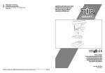
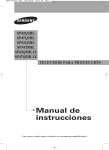
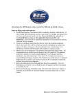
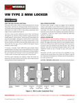
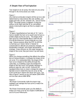
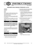
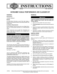
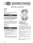
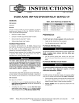
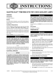
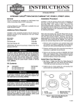
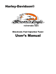
-J05427
REV. 2011-03-03
SE LEFT (SPROCKET) CRANKSHAFT ROLLER BEARING KIT
Kit Contents
GENERAL
Kit Number
Table 1. Kit Contents
24004-03B
Description (Quantity)
Models
For model fitment information, see the Screamin' Eagle Pro
Racing Parts catalog (English only).
Additional Parts Required
Bearing, flywheel (left side)
24605-07
Ring, retaining
35114-02
Washer, thrust (2) (service version)
8972
Race, inner
Not Sold Separately
NOTE
You will need to obtain a 2003 or later service manual when
performing this bearing installation on either a 1999 through
2002, or a 2003 or later Twin Cam model motorcycle.
You will need to obtain a 2007 or later service manual when
performing this bearing installation on 2006 Twin Cam Dyna
models, or all other 2007 Twin Cam model motorcycles.
In addition to the above kit components, this installation will
require the separate purchase of an Oil Seal (H-D Part Number
12068).
Installation on a 1999 through 2002 engine will also require
the separate purchase of one of the following spacers:
Part Number
INSTALLATION
1.
Remove the engine from the motorcycle chassis. Refer
to REMOVING ENGINE FROM CHASSIS in the applicable
service manual.
2.
Follow the instructions under TOP END OVERHAUL in
the service manual to disassemble the engine top end.
3.
See BOTTOM END OVERHAUL to disassemble the
engine bottom end.
•
H-D Part Number 24008-03 (1.54 inch, 39 mm long), for
FLT models
4.
Refer to CRANKCASE DISASSEMBLY to disassemble
the crankcase.
•
H-D Part Number 24038-03 (1.33 inch, 34 mm long), for
Dyna models
5.
See LEFT CRANKCASE HALF to remove the crankshaft
from the left crankcase half.
•
H-D Part Number 24039-03 (1.43 inch, 36 mm long), for
Softail models
6.
For 2003 and later models with stock flywheel, proceed
to:
•
"Thrust Washer and Bearing Race Removal/ Installation,
2003 and Later Models with Stock Flywheel" or
•
"Flywheel Removal/ Installation, Models with 2003-Style
Crankcase"
The rider's safety depends upon the correct installation
of this kit. Use the appropriate service manual procedures.
If the procedure is not within your capabilities or you do
not have the correct tools, have a Harley-Davidson dealer
perform the installation. Improper installation of this kit
could result in death or serious injury. (00333a)
NOTE
For 1999-2002 models with stock flywheel and for 1999
and later models with Screamin' Eagle Stroker flywheel
and 2003-Style Crankcase, see Figure 1. Follow the instructions in the applicable 1999-2002 service manual to remove
the existing tapered roller bearing from the crankshaft, then
perform the following steps.
This instruction sheet references service manual information.
A service manual for your model motorcycle is required for this
installation and is available from a Harley-Davidson Dealer.
-J05427
Many Harley-Davidson® Parts & Accessories are made of plastics and metals which can be recycled.
Please dispose of materials responsibly.
1 of 6
is02877
7
1
3
2
Be sure to follow manufacturer's instructions when using
the Robinair Heat Gun or any other radiant heating device.
Failure to follow manufacturer's instructions can cause a
fire, which could result in death or serious injury. (00379a)
9
4
8
3
4
1.
2.
3.
4.
5.
6.
7.
8.
9.
5
•
Always keep hands away from tool tip area and heat shrink
attachment.
•
Be sure to turn the "ON/OFF" switch to the "OFF" position
after use.
2.
Place the new bearing inner race (3) on a bench top. Using
the Robinair Heat Gun (HD-25070), uniformly heat the
bearing inner race for about 60 seconds, using a circular
motion.
3.
Wearing suitable gloves to protect hands from burns, place
the heated bearing inner race over the sprocket shaft with
number on bearing facing up.
6
Flywheel and rod assembly
Sprocket shaft (on item 1)
Bearing cone (2)
Bearing outer race (2)
Lock ring
Shim, bearing
Crankcase (left half shown)
Oil seal
Spacer, sprocket shaft
Figure 1. Crankcase Removal, 1999-2002 Models with Stock
Flywheel in 2003-Style Crankcase or 1999 and later Models
with Screamin' Eagle Stroker Flywheel in 2003-Style
Crankcase
NOTE
To facilitate installation without heat, apply a light penetrating
oil to shaft and leading edge of bearing inner race.
NOTE
Never use both heat and penetrating oil. Use only one or the
other. Heat can cause the penetrating oil to ignite resulting in
flames or fire.
is02916
THRUST WASHER AND BEARING RACE
INSTALLATION
1999-2002 Models with Stock Flywheel in 2003-Style
Crankcase
1999 and Later Models with Screamin' Eagle Stroker Flywheel in 2003-Style Crankcase
NOTE
On the models listed above, you will be removing the bearing
cone from the sprocket shaft and replacing it with a thrust
washer and bearing race from the new Roller Bearing Kit.
Follow the instructions in the applicable service manual to
remove the tapered roller bearing from the left crankcase half
and the bearing cone from the crankshaft.
Figure 2. Sprocket Shaft Bearing Installer (Part Number
HD-97225-55C)
4.
Perform the following steps to install the new thrust washer
and roller bearing race to the crankshaft, then follow the
instructions in the 2003 or later service manual to install the
new roller bearing to the crankcase half.
1.
See Figure 5. Obtain a thrust washer (2) from the kit. Place
the new thrust washer over the sprocket shaft (1) with the
ink stamp facing outside (and the chamfer on the ID toward
the flywheel).
5.
-J05427
Obtain the SPROCKET SHAFT TAPERED ROLLER
BEARING CONE INSTALLER (HD-97225-55B). See
Figure 2. Assemble the tool as described below:
a.
See Figure 3. Sparingly apply graphite lubricant to
the threads of the pilot shaft (1) to prolong service life
and verify smooth operation.
b.
Thread the pilot onto the sprocket shaft (8) until contact is made with the shoulder.
c.
Slide the sleeve (5) over the pilot until it contacts the
bearing race (6).
d.
Slide the thrust bearing (4) and large flat washer (3)
over the pilot until contact is made with the sleeve.
e.
Thread the handle (2) onto the pilot shaft.
See Figure 4. Rotate the handle of the tool in a clockwise
direction until the bearing inner race bottoms against the
thrust washer.
2 of 6
is02879
1
2
is02881
3
2
8*
2
9
3
4
5
6
3
1
1.
2.
3.
4.
5.
6.
7.
8.
7
8
7
Pilot shaft
Handle
Flat washer
Thrust bearing
Sleeve
Inner race
Thrust washer
Sprocket shaft
Figure 3. Inner Race Installation
is02880
1.
2.
3.
4.
5.
6.
7.
8.
9.
2
4
5
6
Flywheel assembly (existing)
Thrust washer (2) (from kit)
Bearing inner race (from kit)
Lock ring (from kit)
Straight roller bearing (from kit)
Crankcase (left half shown) (new)
Seal (purchased separately)
Spacer (purchased separately) (See Table 1)
Chamfer
Figure 5. Crankcase Installation, 1999-2002 Models with
Stock Flywheel in 2003-Style Crankcase or 1999 and Later
Models with Screamin' Eagle Stroker Flywheel in 2003-Style
Crankcase
THRUST WASHER AND BEARING
REMOVAL AND INSTALLATION
2003 and Later Models with Stock Flywheel
NOTE
On the models listed above, you will be removing the existing
bearing race and thrust washer from the sprocket side of the
crankshaft (see Figure 6) and replacing them with a new race
and thrust washer.
Follow the instructions in the appropriate service manual to
remove the existing bearing from the left crankcase half, then
add the following procedures to remove and replace the existing
bearing race and thrust washer onto the crankshaft.
Figure 4. Inner Race onto Sprocket Shaft Installation
6.
Remove the handle, flat washer, thrust bearing, sleeve
and pilot from the sprocket shaft.
7.
See Figure 5. Follow instructions in the 2003 or later service manual for assembly of the remaining components,
crankcase assembly and installation in the chassis.
-J05427
3 of 6
is02882
2
8
3
10
NOTE
For proper clamping force, hold-down clamp must not be tilted.
Rotate hex on outboard stud until clamp is level.
4.
9
5
1
88
4
4
6
7
1. Flywheel assembly (existing, includes items 2
and 3)
2. Thrust washer (remove and replace)
3. Bearing inner race (remove and replace)
4. Thrust washer (2) (from kit)
5. Bearing inner race (from kit)
6. Lock ring (from kit)
7. Straight roller bearing (from kit)
8. Crankcase (left side shown) (save existing parts)
9. Seal (purchased separately)
10. Spacer (save existing part)
Install wedge attachment only so far as necessary to
ensure positive contact with bearing inner race. Installing
tool with more contact than necessary will result in damage
to the flywheel (00500b)
5.
Obtain two 3/8-16 x 6-1/2 inch long bolts and flat washers.
Install the flat washers on the bolts. Obtain the bridge,
forcing screw and hardened plug from the MAINSHAFT
BEARING INNER RACE PULLER/ INSTALLER (HD34902B).
6.
Slide one bolt into the channel on each side of the bridge
so that the flat washer is between the bridge and bolt head.
Thread the bolts into the wedge attachment an equal
number of turns.
7.
Sparingly apply graphite lubricant to the threads of the
forcing screw to prolong service life and verify smooth
operation. Start the forcing screw into the center hole of
the bridge.
Figure 6. Bearing and Thrust Washer Installation, 2003 and
Later Models with Stock Flywheel
Removal
1.
2.
See Figure 7. Position the WEDGE ATTACHMENT (HD95637-46A) on the inboard side of the thrust washer, and
turn the hex nuts an equal number of turns to draw the
halves of the wedge together.
Obtain FLYWHEEL SUPPORT FIXTURE (HD-44358),
see Figure 7. Install brass jaws or shop towels around the
teeth of a vise to prevent tool damage. Clamp the tool in
the vise with the round hole topside.
Insert the right-side crankshaft end through the hole,
resting the flywheel assembly on the fixture. Slide the
knurled locating pin down the slot in the tool to engage
the crank pin hole. Hand tighten the locating pin.
NOTE
Failure to use hardened plug may result in damage to forcing
screw and/or sprocket shaft.
8.
Place the cupped side of the hardened plug against the
end of the sprocket shaft. Thread the forcing screw into
the bridge until the steel ball at the end of the screw makes
firm contact with the hardened plug.
is02883
1
2
1. Hold down clamp (2)
2. Locating pin
Figure 7. Flywheel Fixture (Part Number HD-44358)
3.
Slide the hold-down clamp down the slot to engage the
inboard side of the right flywheel half, then hand tighten
the knurled nut at the bottom to secure. Repeat this step
to secure the hold-down clamp on the opposite side of the
flywheel.
-J05427
4 of 6
is02884
is02885
1
1
2
2
3
7
4
4
5
3
6
7
6
1.
2.
3.
4.
5.
6.
7.
5
Forcing screw
3/8-16 bolt
Bridge
Hardened plug
Wedge attachment
Bearing inner race
Sprocket shaft
1.
2.
3.
4.
5.
6.
7.
Pilot shaft
Handle
Flat washer
Thrust bearing
Sleeve
Inner race
Thrust washer
Figure 9. Thrust Washer and Bearing Inner Race
Installation
is02886
Figure 8. Inner Race From Sprocket Removal
Be sure to follow manufacturer's instructions when using
the Robinair Heat Gun or any other radiant heating device.
Failure to follow manufacturer's instructions can cause a
fire, which could result in death or serious injury. (00379a)
•
Always keep hands away from tool tip area and heat shrink
attachment.
•
Be sure to turn the "ON/OFF" switch to the "OFF" position
after use.
9.
Using the Robinair Heat Gun (HD-25070), uniformly heat
the bearing inner race for about 30 seconds.
NOTE
To facilitate removal without heat, apply a light penetrating oil
to shaft and leading edge of bearing inner race.
NOTE
Never use both heat and penetrating oil. Use only one or the
other. Heat can cause the penetrating oil to ignite resulting in
flames or fire.
10. Turn the forcing screw until the thrust washer (and bearing
inner race) moves approximately 1/8 inch (3.2 mm).
11. Turn the hex nuts an equal number of turns to separate
the halves of the WEDGE ATTACHMENT.
-J05427
Figure 10. Inner Race onto Sprocket Installation
12. After bottoming the thrust washer on the shaft, reposition
the WEDGE ATTACHMENT (HD-95637-46A) on the
inboard side of the bearing inner race. Turn the hex nuts
an equal number of turns to draw the halves of the wedge
together.
5 of 6
4.
Install wedge attachment only so far as necessary to
ensure positive contact with bearing inner race. Installing
tool with more contact than necessary will result in damage
to the flywheel (00500b)
See Figure 2. Obtain the SPROCKET SHAFT TAPERED
ROLLER BEARING CONE INSTALLER (HD-97225-55C).
Assemble tool as described below.
a.
Thread the pilot onto the sprocket shaft until contact
is made with the shoulder.
b.
Sparingly apply graphite lubricant to the threads of
the pilot shaft to prolong service life and verify smooth
operation.
c.
Slide the sleeve over the pilot until it contacts the
bearing race.
d.
Slide the thrust bearing and large flat washer over
the pilot until contact is made with the sleeve.
e.
See Figure 9. Thread the handle onto the pilot shaft.
13. Verify that the tool assembly is square, so that the bearing
inner race is not cocked during removal.
14. See Figure 8. Using the Robinair Heat Gun (HD-25070),
uniformly heat the bearing inner race for about 30 seconds
using a circular motion.
NOTE
To facilitate removal without heat, apply a light penetrating oil
to shaft and leading edge of bearing inner race.
15. Turn the forcing screw until the bearing inner race is pulled
free of the sprocket shaft.
16. Remove the thrust washer from the sprocket shaft.
5.
See Figure 10. Rotate the handle of the tool in a clockwise
direction until the bearing inner race bottoms against the
thrust washer.
6.
Remove the handle, flat washer, thrust bearing, sleeve
and pilot from the sprocket shaft.
7.
Follow the instructions in the applicable service manual
for assembly of the remaining components, crankcase
assembly and installation in the chassis.
17. Discard the bearing inner race and thrust washer.
Installation
NOTE
DO NOT re-use the thrust washer removed from the sprocket
shaft in the previous step.
1.
2.
3.
Place a new thrust washer (4) from the kit over the
sprocket shaft with the ink stamp facing outside (and the
chamfer on the ID toward the flywheel).
Place the new bearing inner race (5) on the bench top.
Using the Robinair Heat Gun (HD-25070), uniformly heat
the bearing inner race for about 60 seconds using a circular motion.
2003-Style Flywheel Removal and Installation
NOTE
The bearing race and one thrust washer will be discarded from
the kit (see Figure 6) as the new flywheel comes with a race
and thrust washer installed.
1.
Follow the instructions in the 2003 or later service manual
to remove the existing bearing from the left crankcase half.
2.
Follow the instructions in the service manual for assembly
of the new bearing (7) and lock ring (6) into the left half of
the crankcase.
3.
Refer to CRANKCASE ASSEMBLY to assemble the
crankcase, using the new thrust washer (4) from the kit,
and a new Oil Seal (H-D Part Number 12068), available
separately.
Wearing suitable gloves to protect hands from burns, place
the heated bearing inner race over the sprocket shaft.
NOTE
To facilitate installation without heat, apply a light penetrating
oil to shaft and leading edge of bearing inner race.
NOTE
Never use both heat and penetrating oil. Use only one or the
other. Heat can cause the penetrating oil to ignite resulting in
flames or fire.
NOTE
If installing the engine on a 1999 through 2002 vehicle, also
install a new spacer. See the listing on Page 1 of these
instructions for the correct spacer for your model motorcycle.
Failure to install correct spacer will lead to insufficient
clearance between the alternator rotor and stator, which
can result in a failed charging system. (00501b)
-J05427
4.
See BOTTOM END OVERHAUL to assemble the engine
bottom end.
5.
Follow the instructions under TOP END OVERHAUL in
the service manual to assemble the engine top end.
6.
Install the engine into the motorcycle chassis. Refer to
INSTALLING ENGINE IN CHASSIS in the service manual.
6 of 6