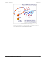
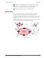
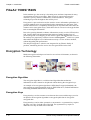
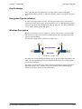
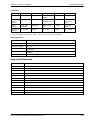
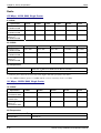
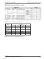
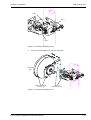
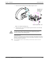
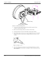
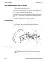
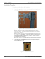
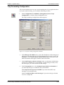
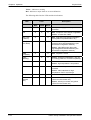
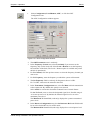
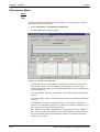
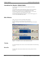
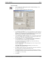
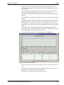
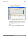
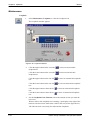
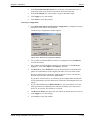
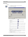
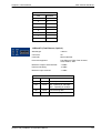
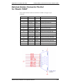
1
® FibeAir Family FibeAir 1500/1528 FibeAir 1500A/1528A FibeAir 1500S/1528S FibeAir 1500P FibeAir 1500AL With CeraView® Java High & Ultra High Capacity Wireless Network Systems Installation and Operation Manual Part ID: BM-0074-7 Doc ID: DOC-00006643 REV H April 2005 Notice This document contains information that is proprietary to Ceragon Networks Ltd. No part of this publication may be reproduced, modified, or distributed without prior written authorization of Ceragon Networks Ltd. This document is provided as is, without warranty of any kind. Registered TradeMarks Ceragon Networks® is a registered trademark of Ceragon Networks Ltd. FibeAir® is a registered trademark of Ceragon Networks Ltd. CeraView® is a registered trademark of Ceragon Networks Ltd. Other names mentioned in this publication are owned by their respective holders. TradeMarks CeraMapTM, ConfigAirTM, PolyViewTM, EncryptAirTM, CeraMonTM, EtherAirTM, and MicroWave FiberTM, are trademarks of Ceragon Networks Ltd. Other names mentioned in this publication are owned by their respective holders. Statement of Conditions The information contained in this document is subject to change without notice. Ceragon Networks Ltd. shall not be liable for errors contained herein or for incidental or consequential damage in connection with the furnishing, performance, or use of this document or equipment supplied with it. Information to User Any changes or modifications of equipment not expressly approved by the manufacturer could void the user’s authority to operate the equipment and the warranty for such equipment. Copyright © 2005 by Ceragon Networks Ltd. All rights reserved. Corporate Headquarters: Ceragon Networks Ltd. 24 Raoul Wallenberg St. Tel Aviv 69719, Israel Tel: 972-3-645-5733 Fax: 972-3-645-5499 Email: [email protected] North American Headquarters: Ceragon Networks Inc. 10 Forest Avenue, Paramus, NJ 07652, USA Tel: 1-201-845-6955 Toll Free: 1-877-FIBEAIR Fax: 1-201-845-5665 Email: [email protected] www.ceragon.com European Headquarters: Ceragon Networks (UK) Ltd. 4 Oak Tree Park, Burnt Meadow Road North Moons Moat, Redditch, Worcestershire B98 9NZ, UK Tel: 44-(0)-1527-591900 Fax: 44-(0)-1527-591903 Email: [email protected] APAC Headquarters Ceragon Networks (HK) Ltd. Singapore RO Level 34 Centennial Tower 3 Temasek Avenue Singapore 039190 Tel - + 65 6549 7886 Fax: +65 6549 7011 Safety Precautions The following safety precautions should be observed when working with fiber optic lines. ! ! ! Before turning on the equipment, make sure that the fiber optic cable is intact and is connected to the transmitter. Do not attempt to adjust the laser drive current. Do not use broken or unterminated fiber optic cables/connectors or look straight at the laser beam. ATTENTION: The laser beam is invisible! ! The use of optical devices with the equipment will increase eye hazard. ! Use of controls, adjustments, or performing procedures other than those specified herein, may result in hazardous radiation exposure. ! When working with FibeAir 1500P, note the following risk of electric shock and energy hazard: Diconnecting one power supply disconnects only one power supply module. To isolate the unit completely, disconnect all power supplies. Contents Chapter 1 Introduction ..........................................................................................1-1 FibeAir 1500/1528 .................................................................................................................... 1-1 FibeAir 1500A/1528A ............................................................................................................... 1-8 FibeAir 1500P......................................................................................................................... 1-12 FibeAir 1500S/1528S ............................................................................................................. 1-14 FibeAir 1500AL....................................................................................................................... 1-18 FibeAir Family System Overview ........................................................................................... 1-19 Chapter 2 Theory of Operation.............................................................................2-1 FibeAir 1500/1528 .................................................................................................................... 2-1 FibeAir 1500A/1528A ............................................................................................................... 2-7 FibeAir 1500P........................................................................................................................... 2-9 FibeAir 1500AL....................................................................................................................... 2-11 FibeAir Family System Specifications .................................................................................... 2-13 Chapter 3 Installation ............................................................................................3-1 General..................................................................................................................................... 3-1 Unpacking Equipment .............................................................................................................. 3-1 Site Requirements.................................................................................................................... 3-1 Before Installing the ODU ........................................................................................................ 3-2 Mediation Device Flange Specifications .................................................................................. 3-3 Required Components and Equipment.................................................................................... 3-3 Suggested Pole Installation...................................................................................................... 3-5 Flow of Operations ................................................................................................................... 3-6 Installing the IDU in a 19" Rack ............................................................................................... 3-7 Setting Up the IDU ................................................................................................................... 3-9 Installation Verification ........................................................................................................... 3-29 ODU Installation for a 6/7/8 GHz System .............................................................................. 3-31 6-8 GHz Frequency Diversity and 2+0 System Installation ................................................... 3-39 6-8 GHz 1+1 System Installation ........................................................................................... 3-44 XPIC Installation and Comissioning ....................................................................................... 3-46 Chapter 4 System Setup .......................................................................................4-1 Prerequisites ............................................................................................................................ 4-1 The Setup Procedure ............................................................................................................... 4-1 Getting Started ......................................................................................................................... 4-2 Setup for FibeAir 1500/1528/1500A/1528A ............................................................................. 4-4 Setup for FibeAir 1500P......................................................................................................... 4-15 Post Setup Procedure ............................................................................................................ 4-26 Chapter 5 Operation ..............................................................................................5-1 General..................................................................................................................................... 5-1 Installation ................................................................................................................................ 5-2 CeraView Configuration ........................................................................................................... 5-5 CeraView Security.................................................................................................................... 5-8 Trap Forwarding Configuration Utility..................................................................................... 5-12 FibeAir Family Installation and Operation Manual i Contents Logging in to CeraView .......................................................................................................... 5-15 CeraView for FibeAir 1500/1528 ............................................................................................ 5-16 CeraView for FibeAir 1500A/1528A ....................................................................................... 5-44 CeraView for FibeAir 1500P................................................................................................... 5-81 CeraView for FibeAir 1500AL............................................................................................... 5-117 Chapter 6 Troubleshooting................................................................................... 6-1 General..................................................................................................................................... 6-1 Maintenance Policy .................................................................................................................. 6-1 Visual Inspection ...................................................................................................................... 6-2 Troubleshooting........................................................................................................................ 6-2 FibeAir 1500/1528 Alarm Messages ...................................................................................... 6-16 Alarm Log File Messages....................................................................................................... 6-17 FibeAir 1500P Alarm Messages............................................................................................. 6-25 Hitless System Alarm Messages............................................................................................ 6-33 Chapter 7 Protection Configuration..................................................................... 7-1 FibeAir 1500/1528 Protection................................................................................................... 7-1 FibeAir 1500A/1528A System Protection................................................................................. 7-9 6-15 GHz FibeAir System Diversity Protection ...................................................................... 7-16 FibeAir 1500P Protection ....................................................................................................... 7-19 FibeAir 1500P Protected 2+2 Configuration .......................................................................... 7-21 Chapter 8 Line Interfaces ..................................................................................... 8-1 General..................................................................................................................................... 8-1 Main Channel Interfaces .......................................................................................................... 8-1 Wayside Channel Interfaces .................................................................................................... 8-7 Order Wire Channel Interface .................................................................................................. 8-9 User Channel Interface ............................................................................................................ 8-9 Appendix A SLIP/PPP Driver Installation ........................................................... A-1 Installation for Windows 98 ...................................................................................................... A-1 Installation for Windows NT ..................................................................................................... A-5 Installation for Windows 2000 .................................................................................................. A-7 Appendix B Connector Pin-Outs......................................................................... B-1 Alarm I/O Connector Pin-Out for FibeAir 1500/1528 ............................................................... B-2 External Alarms Connector Pin-Out for FibeAir 1500P............................................................ B-3 Protection Connector Pin-Out for FibeAir 1500P ..................................................................... B-4 8 x E1/T1 Connector Pin-Out for FibeAir 1500P...................................................................... B-4 User Channel Cable Pin-Out.................................................................................................... B-5 Modem-PPP Cross Cable Pin-Outs ......................................................................................... B-5 Protected System Cables......................................................................................................... B-6 Impedance Cable Pin-Out........................................................................................................ B-7 RJ-45 10-Pin Connector for Hitless Systems........................................................................... B-8 Wayside Channel Connector Pin-Outs .................................................................................... B-9 ii FibeAir Family Installation and Operation Manual Contents Appendix C Antenna Information........................................................................ C-1 Appendix D Frequency Information .................................................................... D-1 FCC Channel Allocations, 16 QAM..........................................................................................D-1 FCC Channel Allocations, 128 QAM........................................................................................D-2 ETSI Channel Allocations, 16 QAM .........................................................................................D-3 ETSI Channel Allocations, 128 QAM .......................................................................................D-4 Deutsch Telecom Channel Allocations, 128 QAM ...................................................................D-8 Japan Channel Allocations, 16 QAM .......................................................................................D-9 China Channel Allocations, 16 QAM........................................................................................D-9 Argentina Channel Allocations, 16 QAM..................................................................................D-9 Argentina Channel Allocations, 128 QAM..............................................................................D-10 FibeAir Family Installation and Operation Manual iii Chapter 1 Introduction FibeAir 1500/1528 FibeAir™ 1500/1528 is a member of the Ceragon Networks® new-generation of Digital Radio Relay Systems (DRRS). FibeAir is a compact, flexible, easy-todeploy and cost-effective product designed to support high capacity voice, data, and video applications in Wide Area Networks (WANs), and Metropolitan Area Networks (MANs). FibeAir System FibeAir systems operate in the 6 to 38 GHz frequency bands and carry medium and high capacity payloads in accordance with ETSI and ITU-T standards, for worldwide operation. FibeAir provides operators with a wireless-based network solution offering fiberlike quality of service. The system’s all digital design provides superior radio performance resulting in an extremely low residual BER, and, consequently, an extremely low cost alternative to metropolitan fiber lines. FibeAir is designed especially for SDH/SONET and IP based networks, as well as microwave ATM, ensuring safe routing of ATM cells. FibeAir Family Installation and Operation Manual 1-1 Chapter 1 Introduction Features As a software-oriented system, FibeAir deploys state-of-the-art digital technology. Together with its integrated SNMP agent, FibeAir can be controlled either by the company’s management software or interfaced to the Telecommunication Management Network (TMN) of the service provider. CeraView™, Ceragon’s SNMP-based GUI element manager, and PolyView™, Ceragon’s open interface network management software, run on Windows 98/2000/NT and over HP OpenView (Windows or UNIX). Features Compact and easy to install. All system setups and configurations are software-determined, including operating frequency channel. Internal multiplexer supports most relevant physical interfaces and data rates. Forward Error Correction (FEC) coding for improved performance. Special optimization for safe ATM transports Advanced digital signal processing implementing all-digital adaptive equalization, tracing loops, IF modulation/demodulation. High spectral efficiency due to advanced modulation (16/128 QAM). 13 external input and output alarms. Local display of far-end terminal status. Remote software downloads for easy upgrades. Loopback control for easy fault isolation. In-band management implementation. Unique SNMP-based management, with user friendly GUI, operating on Windows or UNIX platforms. Protected and non-protected configurations. Hitless, errorless diversity protection switching. Applications FibeAir 1500/1528 is a natural choice for metropolitan SONET, SDH, ATM, and IP networks. The system is used for ring closures, ring/LAN interconnections and access to remote distribution nodes. The system may be used either as a transparent alternative to fiber lines, or as a redundant link, providing media diversity protection. FibeAir’s low frequency links (6-15 GHz) enable longer operating distances, essential for cellular backbones, ILEC/CLEC backbones, and large enterprises. Together, Ceragon’s high and low frequency links provide a comprehensive onevendor wireless communication solution. 1-2 FibeAir Family Installation and Operation Manual Chapter 1 Introduction Applications The following are typical FibeAir 1500/1528 applications: SONET/SDH Networks Cellular Networks - MSC to BSC UPSR Ring ATM Networks Corporate/Campus Networks LMDS Backhaul SONET/SDH Networks SONET/SDH Network Enhancement FibeAir 1500/1528 is a revolutionary compact wireless solution for metropolitan high capacity SONET/SDH networks. In access applications, the system provides a ”last mile” high bit rate connection to large corporate networks or to remote distribution node carrying data, video and voice to multiple subscribers. FibeAir includes an internal multiplexer that can provide a combination of OC-3/STM-1, DS3/E3, Ethernet/Fast Ethernet, T1/E1 interfaces. As a SONET/SDH network element, FibeAir can perform ring closures, ring interconnections and carry IP or ATM traffic over SONET/SDH. FibeAir Family Installation and Operation Manual 1-3 Chapter 1 Introduction Applications Cellular Networks - MSC to BSC UPSR Ring Cellular Networks - MSC to BSC UPSR Ring High speed links allow for expansion of capacity in Cellular systems. Especially well-suited for creation of dense micro-cells. Microwave ATM Networks ATM was originally designed for transmission over error-free channels (e.g. fibers). Radio transmission is challenged by ATM, and ATM’s basic and simple error correction mechanism needs to be strengthened for transmission over actual radio links. Ceragon has chosen an ATM design solution, one that significantly improves the important cell transfer parameters. Furthermore, Ceragon’s approach is optimized for ATM transport, but is also suitable for high-performance transmission of other payloads (e.g. SONET/SDH, Packet over SONET). No special configuration via management is required for any payload type. The FibeAir system is optimally designed for microwave ATM transmission. Advanced algorithms minimize cell loss (CLR) and cell miss-insertion (CMR), and together with error correction mechanisms, ensure fiber-like quality transmission. The system can be integrated with ATM NTUs (Network Termination Units) and ATM access concentrators offering a wide variety of access solutions in capacities ranging from DS3/E3 to 155 Mbps. 1-4 FibeAir Family Installation and Operation Manual Chapter 1 Introduction Applications Microwave ATM Networks FibeAir 1500/1528 supports various services (CBR, VBR, and ATM UNI) at the customer premises. Designed for the most demanding data applications, FibeAir 1500/1528 meets the most stringent QoS requirements. Corporate/Campus Networks The FibeAir 1500/1528 system is a flexible, cost-effective solution for corporate networks and campus environment presenting a point-to-point, end-to-end broadband wireless alternative to expensive leased fiber lines. The FibeAir system provides a “one box” solution by integrating services such as Fast Ethernet, data, video and voice. For pure Ethernet applications, FibeAir 1528 can be used to create virtual networks for LAN users (VLANs). FibeAir 1500/1528 provides two Fast Ethernet (100BaseTX) connections over 155 Mbps. In addition, the FibeAir 1000 Digital Radio system offers LAN-to-LAN and PBX connectivity for campus networks, large enterprises, and metro last mile access. The system provides full throughput (up to 116 Mbps) Fast Ethernet connectivity together with up to 8 E1/T1 ports for TDM based information. Corporate/Campus Networks FibeAir Family Installation and Operation Manual 1-5 Chapter 1 Introduction Applications Integral Multiplexer In the Telecom and Datacom environment, different interfaces are used. The FibeAir integral multiplexer supports both Telecom and Datacom interfaces by mapping the different data streams into the SONET/SDH payload. The following applications using the FibeAir 1500/1528 system are available: Fast Ethernet and DS3/E3 - combines wireless Fast Ethernet and DS3/E3 interfaces for various applications such as the corporate and campus environment. Fast Ethernet and 8xE1/T1 - combines wireless Fast Ethernet and 8xE1/T1 interfaces for various applications that require E1/T1 tributary lines. 3XE3, 3XDS3 - broadband wireless solutions for Wide Area Networks (WANs), Metropolitan Area Networks (MANs) and Corporate/Campus applications. 2XFast Ethernet - wireless Fast Ethernet applications for the Corporate and Campus environment and Internet Service Providers (ISPs). The following figure illustrates a Telecom and Datacom Convergence wireless network. Telecom/Datacom Convergence 1-6 FibeAir Family Installation and Operation Manual Chapter 1 Introduction Applications LMDS Backhaul LMDS Backhaul The high capacity FibeAir 1500/1528 is the ideal wireless building block for the LMDS Backhaul network. Operating in the LMDS frequency bands, the system offers a wireless SONET/SDH ring solution delivering high spectral efficiencies. The system can also provide 155Mbps link from a hub to a large customer, and additional connections can be made to the PSTN and ISP. FibeAir Family Installation and Operation Manual 1-7 Chapter 1 Introduction FibeAir 1500A/1528A FibeAir 1500A/1528A Ceragon’s FibeAir Family includes FibeAir 1500A (16 QAM modem) and FibeAir 1528A (128 QAM modem). FibeAir 1500A/1528A is Ceragon’s SDH IDU with a built-in Add-Drop Multiplexer. The built in ADM increases wireless network reliability and reduces overall network cost. Using FibeAir 1500A/1528A saves the network planner a substantial cost of installing a stand-alone ADM at each site where the add/drop-capability requirement does not exceed 32 E1s, and costs for training and spare parts. Until FibeAir 1500A/1528A with its fully integrated ADM was introduced by Ceragon, the company provided point-to-point radio links throughout the world. With the introduction of FibeAir 1500A/1528A, Ceragon has broadened its scope to that of a wireless network solution provider, offering both regenerator and integrated network ADM units. FibeAir 1500A/1528A is a one-box solution for 155 Mbps multiplexed data transmission. The system provides an OC-3/STM-1 wireless ring operating in the 6, 7, 8, 11, 13, 15, 18, 23, 26, 28, 32, and 38 GHz frequency bands. The unit is based on the same field-proven technology as the FibeAir 1500, with the addition and improvement of ADM-specific cards. FibeAir 1500A/1528A supports chain and ring topologies. It can be used in pure SDH wireless networks or in mixed (wired and wireless) networks. The ability to add/drop traffic in each node of the network provides network flexibility and ease of planning. Ring topologies provide traffic protection without the need for redundant radio equipment as is required for protected (1+1) radio configurations. The system supports path protection and synchronization mechanisms, and implements In-Band Management for seamless integration in the network. Ceragon’s management concept involves Ceragon management applications integrated with existing network management platforms. 1-8 FibeAir Family Installation and Operation Manual Chapter 1 Introduction Features FibeAir network management is controlled by Ceragon’s network management software. CeraView™, Ceragon’s SNMP-based GUI element manager, and PolyView™, Ceragon’s open interface network management software, run on Windows 98/2000/NT and over HP OpenView (Windows or UNIX). CeraView and PolyView extend HP OpenView functionality for Ceragon elements in the network. Features The following are features of the 1500A/1528A systems: Optimized carrier class wireless wireline solution for cellular and service providers. Provides up to 31 E1/T1 tributary interfaces per site, optical and/or radio aggregate. Path protection and network synchronization in accordance with SONET/SDH standards. External synchornization inputs/outputs. Unique SNMP-based element and network management, supports path protection and in-band management. Applications FibeAir 1500A/1528A supports ring and chain topologies, with full add-drop functionality and path protection in the ring. As a standard ADM, it can easily be integrated in the network with other vendor equipment. FibeAir’s standard in-band management capability enables management of external equipment and FibeAir products within the SONET/SDH network. External synchronization outputs are used to synchronize external equipment with the network. FibeAir 1500A/1528A also supports cascaded topologies, and enables a “highway” type network that drops E1s/T1s at each node. One possibilty for FibeAir 1500A/1528A deployment is as an access network transmission solution. Instead of Fiber-to-Curb/Building/Office (FTTC/FTTB/FTTO), FibeAir 1500A/1528A can be used for Radio-toCurb/Building/Office (RTTC, RTTB, RTTO). At rapidly developing sites using relatively old optical infrastructures, fiber lines may not reach the customer. In such cases, the service provider can use FibeAir 1500A/1528A units for inter-connection and service distribution. In many cases, customers obtain required capacity via leased lines. FibeAir 1500A/1528A can be used as a cost-effective alternative to leased lines and terminal equipment. In approximately three years, the initial investment in FibeAir 1500A/1528A will be returned, whereas use of leased lines over three years will yield much higher cost. FibeAir Family Installation and Operation Manual 1-9 Chapter 1 Introduction Applications The following illustration shows FibeAir 1500A/1528A integrated in a typical wireless/wireline network. FibeAir 1500A/1528A Integrated in a Wireless/Wireline Network The following illustrations show FibeAir 1500A/1528A wireless network possibilities: FibeAir 1500A/1528A Integrated in a Wireless SDH Access Ring 1-10 FibeAir Family Installation and Operation Manual Chapter 1 Introduction Applications Generic UMTS Network Topology FibeAir 1500A/1528A, with its integrated ADM, can provide the basis for the Level 1 and Level 2 rings shown in the illustration above. FibeAir Family Installation and Operation Manual 1-11 Chapter 1 Introduction FibeAir 1500P FibeAir 1500P FibeAir™ 1500P is Ceragon’s modular ultra high capacity network connectivity solution designed to meet growing market demands for increased spectral-efficient systems. FibeAir™ 1500P is designed to deliver double the capacity using a single 28 MHz channel. In addition, the system is modular, easy to install, and a cost-effective alternative to fiber. With FibeAir™ 1500P operating in co-channel dual polarization (CCDP) mode, using the cross polarization interference canceller (XPIC) algorithm, two STM-1 signals can be transmitted over a single 28 MHz channel, using vertical and horizontal polarization. This enables double capacity in the same spectrum bandwidth. A cost-effective STM-1 ring configuration is achieved using a single FibeAir™ 1500P IDU located at each of the nodes, with one ODU providing the West connection and another providing the East connection. For upgrading to a 311 Mbps ring, the built in CCDP mode can be activated to use the same single 28 MHz channel and equipment. FibeAir™ 1500P can also be configured as an STM-1 1+1 hot standby terminal, in a 1U IDU shelf, with either a single or double antenna installation. FibeAir™ 1500P is equipped with an internal SNMP agent for easy integration with standard network management systems, and can also be managed via CeraView®, Ceragon’s network element manager, and PolyView™, Ceragon’s network management platform. FibeAir™ 1500P also provides an internal Ethernet hub for in-band transmission of third party management information. As with other FibeAir™ Family products, FibeAir™ 1500P can operate together with any industry standard ADM. Feaures FibeAir™ 1500P features include the following: 311 Mbps over a single 28 MHz channel Cost-effective 155 Mbps ring solution, providing single 1U IDU for EastWest connectivity Modular design for easy capacity upgrade Cost-effective 155 Mbps hot standby protection system Built-in Ethernet hub for in-band transmission of third party management information Operates in the 6-38 GHz frequency bands Compact, single 1U height IDU 1-12 FibeAir Family Installation and Operation Manual Chapter 1 Introduction Applications Additional E1/T1 or Ethernet (10BaseT) over 2 Mbps Wayside Channel CeraView®, Java based SNMP element management application, and PolyView™, open interface network management application Supports FCC, ETSI, ITU-R, ITU-T, and IEEE standards Applications FibeAir 1500P can be configured as a cost-effective STM-1 ring solution, providing a single one-rack unit height IDU installation at any ring node. Each node on the STM-1 ring consists of a single 1U Indoor Unit, providing both East and West connectivity at 155 Mbps, connecting to two Outdoor Units, East and West. FibeAir equipment supports co-channel dual polarization (CCDP) mode, for future upgrade to 311 Mbps capacity over a single 28 MHz channel. Single IDU Solution FibeAir Family Installation and Operation Manual 1-13 Chapter 1 Introduction FibeAir 1500S/1528S FibeAir 1500S/1528S In this modern age, data security is becoming more and more important for many organizations and service providers. Data security is required to protect the customer’s privacy and the confidentiality of their businesses. Encryption technologies provide the highest data security level. Encryption is a process that inverts the sensitive source information (plain data) to a pseudo-random series (encrypted data) before transmitting it to the target. This pseudo-random series is completely meaningless for all parties that don’t share the common secret (encryption keys), while those who do can use it to decrypt the data back to meaningful information. Due to the growing demand to enhance information security over the PTP wireless link, Ceragon Networks implemented the solution of adding another layer of protection against eavesdropping on the wireless signal and unauthorized access to the rooftop. Our proprietary solution is known as EncryptAirTM, which is a system that enables the highest level of information security over the wireless medium, without degrading link performance. The unique EncryptAirTM solution was integrated in our FibeAir family of products, introducing the first carrier class encrypted PTP wireless link. Encryption Technology Modern encryption techniques are based on several crucial elements, as shown in the following illustration: Plain Data Cipher Data Cipher Data Plain Data Encryption Algorithm The encryption algorithm is a uni-directional algorithm that randomizes information so that it cannot be deciphered without having the encryption keys. An example of an encryption algorithm is DES (Data Encryption Standard), the most popular encryption standard, which is FIPS PUBS 46-3 (Federal Information Processing Standards Publications) compliant. Encryption Keys Encryption keys are the common secret between the source and the target, used as an input for the encryption algorithm to encrypt the plain data or decrypt the encrypted data. Encryption keys can be either symmetric or asymmetric. A symmetric key requires the same secret key for both sides of the link. An asymmetric key requires a different secret key for both sides of the link. 1-14 FibeAir Family Installation and Operation Manual Chapter 1 Introduction Encryption Algorithm Key Exchange Since using the same encryption key for a long period of time will degrade encryption reliability, the key is replaced frequently, safely securing the encrypted data. Encryption Synchronization In order to decrypt the data correctly, the decryptor at the receiver side must be synchronized with the encryptor at the transmitter side. A synchronization protocol is used to keep both sides synchronized using the same key, the same initialization vector, and by starting at the same point. Wireless Encryption Wireless connections are more complex to encrypt. The need to overcome BER and fades in the radio channel, while maintaining the radio system performance, requires special handling. The following figure shows a FibeAir encrypted link. Encrypted Data Plain Data FibeAir Encrypted Link The plain data passing through the FibeAir IDU is encrypted and transmitted to the ODU. The encrypted data protects the information flowing to the rooftop against potential eavesdroppers. EncryptAir, Ceragon Networks’ robust encryption mechanism, employs the DES algorithm, which is more suitable for wireless medium, while maintaining the field-proven FibeAir system quality performance. FibeAir Family Installation and Operation Manual 1-15 Chapter 1 Introduction EncryptAirTM - Ceragon Encryption EncryptAirTM - Ceragon Encryption EncryptAir is based on proprietary Ceragon Networks technology and provides the first high capacity (155 Mbps+) wireless encryption connection. EncryptAir implements the DES (Data Encryption Standard) algorithm, which uses symmetric encryption keys, a common secret between source and target, in order to encrypt/decrypt the data. EncryptAir also implements proprietary algorithms that enable the highest level of information privacy. Once established, each link has a unique set of encryption keys, allowing many links to operate in the same area, with no link intercepting the data of another link. The following figure illustrates Ceragon’s DES implementation. The standard DES core is empowered with Ceragon proprietary protocols to maintain DES algorithm strength in the wireless connection. EncryptAir DES Implementation EncryptAir components include the following: FPGA - The DES core is implemented in hardware to minimize additional end-toend delay. CKEP - Ceragon Key Exchange Protocol CKEK - Ceragon Key Encryption Key CESM - Ceragon Encryption Synchronization Mechanism 1-16 FibeAir Family Installation and Operation Manual Chapter 1 Introduction EncryptAirTM - Ceragon Encryption Automatic Key Management Integrated in the FibeAir 1U IDU, the EncryptAir algorithm is completely transparent to the operator, functioning automatically without the need for manual key loading or replacement. Encryption can be disabled/enabled via the CeraView® management application. Keys are the most important part of the encryption algorithm. Knowing the correct key enables the decryption of encrypted information. Not knowing the key makes it impossible to decrypt the data. Since there are more than 70,000,000,000,000,000 (seventy quadrillion) possible keys, the possibility of discovering a particular key is extremely unlikely when typical eavesdropping techniques are used. If the key is changed frequently, the risk of its discovery is diminished even further. Unique Ceragon protocols were designed to generate secret keys and keep them safe and un-discoverable. The EncryptAir algorithm consists of random key generation, frequent key replacement, and a unique set of keys for each link, for operation in a dense wireless environment. The key consists of 64 binary digits (0s or 1s), whereby 56 bits are used directly by the encryption algorithm, and the remaining 8 bits are used for error detection (parity). Encryption Performance The encryption algorithm and protocols were designed to overcome BER and fades, enabling smooth operation over the wireless channel. EncryptAir maintains the following system parameters: - Effective bandwidth - Throughput (payload rate) - Delay - BER performance - System threshold (operation distance) Supported Products EncryptAir is available upon request in the following FibeAir Family products: - FibeAir 1500/1528/3100/6200 - SDH/SONET, IP, and ATM traffic - All frequencies (ETSI/FCC) Supported Standards - Federal Information Processing Standards Publications - FIPS PUB 46-3, Compatible (DES) - NIST DES compliant, certification #152, as published in http://csrc.nist.gov/cryptval/des/desval.html FibeAir Family Installation and Operation Manual 1-17 Chapter 1 Introduction FibeAir 1500AL FibeAir 1500AL FibeAir 1500AL is an optical full-functionality SDH ADM (Add-Drop Multiplexer). It supports all ADM features, such as path protection and synchronization, and provides two STM-1 optical aggregates, and n x E1 or STM-1 tributary lines. FibeAir 1500AL supports chain and ring topologies. It can be used in pure SDH wireless networks or in mixed (wired and wireless) networks. The ability to add/drop traffic in each node of the network provides network flexibility and ease of planning. Ring topologies provide traffic protection without the need for redundant equipment as is required for protected (1+1) configurations. The system supports path protection and synchronization mechanisms, and implements In-Band Management for seamless integration in the network. Features The following are features of the 1500AL system: ! Optimized carrier class wireline solution for cellular and service providers. ! Complies with SDH standards. ! Provides up to 16 E1 tributaries, or an STM-1 tributary interface and an electrical/optical aggregate. ! Path protection and network synchronization. ! External synchornization inputs/outputs. ! Unique SNMP-based element and network management, supports path protection, clock synchronization, NTP server connection, and in-band management. ! Up to 4 FibeAir 1500AL IDUs can be stacked to provide connections for up to 63 E1s. Or, alternatively, FibeAir 1500AL can be configured with an STM-1 tributary and an STM-1-to-63 E1 Access Mux. ! Provides remote software download for Ceragon units in the system. Applications FibeAir 1500AL supports ring and chain topologies, with full add-drop functionality and path protection in the ring. As a standard ADM, it can easily be integrated in the network with other vendor equipment. FibeAir’s standard in-band management capability enables management of external equipment and FibeAir products within the SDH network. External clock signals can be input for precise synchronization with other equipment in the network. FibeAir 1500AL also supports cascaded topologies, and enables a “highway” type network that drops E1s at each node. 1-18 FibeAir Family Installation and Operation Manual Chapter 1 Introduction FibeAir Family System Overview FibeAir Family System Overview General The Ceragon FibeAir Family is available in 6-38 GHz frequency bands to meet user requirements. The FibeAir system consists of an Indoor Unit (IDU), an Outdoor Unit (ODU), and a high-performance antenna. (FibeAir 1500AL does not include an ODU and antenna.) FibeAir Main Modules Indoor Unit (IDU) A compact, 17” wide, 1U-high unit, mount compatible for both ETSI and ANSI standard racks. The IDU includes physical line interfaces, a full-function SONET/SDH regenerator internal multiplexer, an advanced modem, and a main manager card. The IDU can also include optional encryption modules for secure data transfer. Indoor Unit (IDU) IDU major functions: Modulate/demodulate the 155 Mbps SONET/SDH payloads. Local and remote system management and control (IDU + ODU). Provide interfaces for 2 Mbps wayside channel, 64 Kbps user channel and 64 Kbps Order Wire channel. Provide I/O line alarms. Integral multiplexer enables Datacom and Telecom applications convergence. FibeAir Family Installation and Operation Manual 1-19 Chapter 1 Introduction FibeAir Family System Overview Outdoor Unit (ODU) ODU Antenna Outdoor Unit (ODU) The ODU consists of high sensitivity RF circuitry with half band tuning range for most frequencies. An independent controller controls the ODU and its functions, and communicates with the IDU. This controller provides the IDU precise received levels (in dBm) and other indications. The ODU, which is adjacent to the antenna, is enclosed in a compact, weatherproof enclosure and connects to the IDU via a single coaxial cable of up to 300 m (1000 ft). ODU major functions: Interface between antenna and IDU (reception/transmission of microwave signals). Power transmission control. Antenna The high-performance antenna is available in the following lengths: 1’ (30 cm), 2’ (60 cm), 3’ (90 cm), 4’ (120 cm), or 6’ (180 cm). For low frequencies (6-11 GHz), other antenna sizes (8-15 ft) are available. CeraView Management Application The system is managed either remotely or locally by CeraView, Ceragon’s SNMPbased software, running on either Windows 98/2000/NT or UNIX platform, with user-friendly graphical user interface. Ceragon NMS functions are in accordance with ITU-T recommendations for TMN. 1-20 FibeAir Family Installation and Operation Manual Chapter 1 Introduction FibeAir Family System Overview CeraView Management Application PolyView Management Application PolyView is Ceragon’s powerful yet user-friendly NMS (Network Management System) that integrates with other NMS platforms (currently HP OpenView), and systems in which no NMS is used. It provides management functions for Ceragon’s FibeAir systems at the network level and individual network element level. PolyView also has its own user-friendly interface called CeraMap (shown in the example below). PolyView Management Application FibeAir Family Installation and Operation Manual 1-21 Chapter 1 Introduction FibeAir Family System Overview In-Band Management In-Band Management refers to a method whereby the network management software sends management packets through the same network it is managing. This differs from out-band management in which the network management software uses a different network (overlay network) in order to communicate with the managed elements. Ceragon IDUs are capable of forwarding IP packets to Ethernet ports, Serial ports, SDH lines (in the overhead) and Radio interfaces (in the overhead). The general idea of In-Band Management is that when a packet arrives at an IDU, the software in the IDU checks the IP packet and follows one of two basic scenarios: If the destination IP address of the packet is the same as the IP address of the IDU, pass the packet to the IP layer for further processing. If the destination IP address of the packet is different than the IP address of the IDU: • If the packet arrived from within the ring, send it to the other side. If that side is down, send it back to its origin. • If the packet arrived from outside the ring, send it to the radio side. If that side is down, send it to the line side. • If the packet belongs to an address outside the ring, send it through the Ethernet port. Ceragon’s FibeAir wireless system provides flexibility in In-Band Management implementation. The following methods can be used to implement In-Band Management in the FibeAir system: Transferring DCCr bytes through the radio and the network. Transferring DCCr bytes through the radio, but not through the network. Transferring DCCr bytes through the 10BaseT wayside channel. Out-of-Band Management Out-of-Band Management refers to a method whereby CeraView management signals are transmitted over E1s using FCD-IP/D routers. It is used when several Ceragon sub-networks (ring and chain) are connected to a SONET/SDH network that includes other vendor equipment which do not transparently transmit the DCCR/DCCM data control channels. In such cases, Ceragon sub-networks employ In-Band Management among themselves, and Out-of-Band Management throughout the rest of the network, via FCD-IP/D routers. Each Ceragon sub-network has a 10BaseT connection to CeraView at the NOC (Network Operation Center). The connection uses one E1 of the transport network, whereby up to 30 sub-networks can be managed using a sinlgle E1 connection. Management data is protected using the RIP protection method. 1-22 FibeAir Family Installation and Operation Manual Chapter 1 Introduction FibeAir Family System Overview Example of Ceragon’s Out-of-Band Management Implementation In the illustration above, the STM-1 ring uses In-Band Management, while the STM-4 ring uses Out-of-Band Management. FibeAir Family Installation and Operation Manual 1-23 Chapter 1 Introduction FibeAir Family System Overview Interfaces The following interfaces are common to some FibeAir systems. Consult the relevant FibeAir interface description below for specific availability. Wayside Channel Interface Plug-in 1.544/2.048 Mbps interface module with standard connectors: T1/E1, ITU-T G.703 (supports either balanced or unbalanced interface, BNC connector). V.35, X.21, RS-530, V.36 (relevant connectors). Ethernet bridge (RJ-45 connector). User Channel Interface 64 Kbps interface module with an RS-232/V.25 (9-pin) interface or Ethernet bridge (RJ-45). Order Wire Analog Interface Analog audio interface for use with a supplied headset (microphone and earphone) through a standard mini audio jack. A buzzer and a panel switch (for far-end signaling) are also included. External Alarms FibeAir supports 13 programmable floating contacts for external alarms, 8 for input and 5 for output. Protected Configuration FibeAir can be configured for protection based on inter-connection between two or more terminals (see Chapter 7 - Protected Configuration). 1-24 FibeAir Family Installation and Operation Manual Chapter 1 Introduction FibeAir Family System Overview FibeAir 1500/1528 Interfaces FibeAir 1500A/1528A provides the following interfaces: STM-1/OC3 Multi Mode Optical Modules: 1300 nm, ST connector. STM-1/OC3 Single Mode Optical Modules: 1300 nm or 1500 nm, normal or extended range, ST, FC or SC connectors. STM-1/OC3 Electrical (Coax) Modules: CMI coding, 75Ω, BNC connector. FibeAir 1500A/1528A Interfaces FibeAir 1500A/1528A provides the following aggregate interfaces: STM-1/OC3: multi-mode optical modules, 1300 nm, ST connector. STM-1/OC3: single mode optical modules, 1300 nm or 1500 nm, normal or extended range, ST, FC or SC connectors. RF: N-type TDM: E1/T1 tributary, 120/100 Ohm balanced Note: FibeAir 1500A/1528A does not include a Wayside Channel option. FibeAir 1500P Interfaces FibeAir 1500P provides the following interfaces: STM-1/OC-3, Electrical: CMI/BNC STM-1/OC-3, Optical: SM/MM Fast Ethernet: 100BaseTx/Fx TDM: 8 x E1/T1 Note: FibeAir 1500P does not include a User Channel option. FibeAir 1500AL Interfaces FibeAir 1500AL provides the following interfaces: STM-1 Electrical: CMI/BNC STM-1 Optical: SM/MM TDM: 8 x E1/T1 Note: FibeAir 1500AL does not include a Wayside Channel option. FibeAir Family Installation and Operation Manual 1-25 Chapter 2 Theory of Operation This chapter describes the FibeAir Family system and how it operates. The FibeAir design concept is based on universal radio architecture. FibeAir 1500/1528 A FibeAir 1500/1528 radio link consists of two FibeAir terminals. Each terminal includes three major components, IDU, ODU, and Antenna. A single cable, carrying communications and DC power, connects the IDU to the ODU. System Block Diagram The following figure shows the FibeAir 1500/1528 main modules and components. In-Door Unit Out-Door Unit Main Channel 155 Mbps MUX Wayside Channel 2 Mbps FEC + Modem 16/128 QAM Manager Module Cable Combiner Cable Combiner RF T/R Power Supply ODU Control RF Cable Power Supply Figure 2-1 FibeAir 1500/1528 System Block Diagram FibeAir Family Installation and Operation Manual 2-1 Chapter 2 Theory of Operation In Door Unit (IDU) In Door Unit (IDU) The IDU is a compact, 17” wide, 1U-high unit, mount compatible for both ETSI and ANSI standard racks. The IDU modulates/demodulates the 155 Mbps Sonet/SDH payloads, manages local and remote units, provides I/O line alarms, and provides interfaces for 1.544/2.048 Mbps Wayside channel, 64 Kbps User channel and 64 Kbps Order Wire channel. The IDU also interfaces a Local Maintenance Terminal or Network Management System. In addition, status alarms and indicators are provided on the front panel. The main IDU modules include: • Network Interfaces • Multiplexer (MUX) • Modem • Manager Card • Cable Interface • Power Supply Multiplexer The MUX module functions as a Sonet/SDH Regenerator. On the line side it interfaces the OC-3/STM-1 stream, and on the radio side the Modem module. As a regenerator, the MUX either terminates or regenerates the OC-3/STM-1 RSOH. In one direction, the OC-3/STM-1 stream, interfacing through the MUX Rx line input terminates and the resulting stream is transmitted to the Modulator in the Modem module. In the opposite direction, the stream coming from the Modem’s Demodulator, undergoes OC-3/STM-1 Regeneration in the MUX, and transmitted through the MUX Tx line output. In addition, the MUX module uses the OC-3/STM-1 SOH bytes to support other services: 1.544/2.048 Mbps Wayside channel and management, 64 Kbps User Channel and Order Wire channel. The MUX module may be configured via software for transparency of most of the SOH bytes for maximum system transparency and non-intervention, at the cost of reduced functionality and services. The multiplexer module enables to integrate different interfaces and services into the SDH payload to converge Datacom and Telecom applications. 2-2 FibeAir Family Installation and Operation Manual Chapter 2 Theory of Operation In Door Unit (IDU) Modem FibeAir 1500 is equipped with a 16-state QAM modem. FibeAir 1528 is equipped with a 128-state QAM modem. The modem delivers a 155 Mbps payload in 50/56 MHz channel bandwidth for 16 QAM, and 27.5/28 MHz for 128 QAM, in compliance with FCC/ETSI standards. The modem is equipped with Digital Signal Processing functions as follows: • Digital IF - I/Q modulator/demodulator whose functions are: - Conversion of the modulated signal to/from the IF frequency. - Automatic level equalization on the signal from ODU. - Protection against overloads. • Timing recovery techniques employing digital tracking loop. • FEC ensures unfaded BER lower than 10-13. The following figure illustrates a measured 16 QAM constellation. Figure 2-2 16 QAM Constellation The following figure illustrates a measured 128 QAM constellation. FibeAir Family Installation and Operation Manual 2-3 Chapter 2 Theory of Operation In Door Unit (IDU) Figure 2-3 128 QAM Constellation Manager Module The Manager module controls and manages all system modules of the local and remote units. The Manager module also supports the user interface through Ethernet or PPP/SLIP to the management station, and an ASCII terminal port. A local or dumb terminal can be used for basic configuration and performance monitoring. Other features include: • Log file • Remote software and firmware download (upgrades can be downloaded from local to remote) • Performance monitoring Cable Interfaces A single coaxial cable connects the IDU to the ODU. This cable carries the following signals: 2-4 • Transmit (350 MHz) and receive (140 MHz) modulated signals. • Transmit (8 MHz) and receive (4 MHz) control data and communications between the IDU manager and the ODU controller. • DC power from the IDU to the ODU (-48 VDC). FibeAir Family Installation and Operation Manual Chapter 2 Theory of Operation Out Door Unit (ODU) The system automatically issues an alarm if the cable is disconnected and provides protection against shorts. Furthermore, there is no need to measure and define the length and type of cable used since the system automatically compensates cable parameters. The following figure illustrates the signal direction through the coaxial cable. -48 VDC ODU TO IDU (CONTROL) IDU TO ODU (CONTROL) TX (PAYLOAD 155M) RX (PAYLOAD 155M) Figure 2-4 Signal Direction Through the Coaxial Cable Power Supplies The power supply features: • Standard Input: -48 VDC • DC input range: -40.5 VDC to -72 VDC • DC/DC converter. • Reverse polarity protection. • Over-voltage and over-current protection. • Detection of IDU-ODU cable alarms (i.e. cable open, cable short). The ODU receives its DC power from the IDU. The PWR LED on the front panel of the IDU continuously lights to indicate the existence of input voltage. Out Door Unit (ODU) The ODU is designed to be fastened to the antenna using four latches. The antenna is mounted on a standard mounting pole. The ODU is enclosed in a compact, weather proof enclosure and connects to the IDU via a single coaxial cable that can extend up to 300m (1000 ft). The ODU major modules include: • T/R Module - A high sensitivity RF circuitry with full band frequency tuning range. • Controller - Controls the ODU and provides ODU status signals, and accurate received signal level (RSL) reading (in dBm). • Cable Combiner. • Power Supply. FibeAir Family Installation and Operation Manual 2-5 Chapter 2 Theory of Operation Out Door Unit (ODU) Latches Figure 2-5 ODU Mounted on the Antenna Note: For FibeAir systems operating at 6, 7, or 8 GHz, the ODU is connected to an external diplexer via an adapter plate. See the end of Chapter 3 - Installation for details concerning the dipelxer. 2-6 FibeAir Family Installation and Operation Manual Chapter 2 Theory of Operation FibeAir 1500A/1528A FibeAir 1500A/1528A FibeAir 1500A/1528A is Ceragon’s SDH IDU with a built-in Add-Drop Multiplexer. The built in ADM increases system reliability and reduces overall system cost. Using FibeAir 1500A/1528A saves the network planner a substantial cost of installing stand-alone ADMs. If site expansion is necessary at a later time beyond 32 E1s, FibeAir 1500A/1528A IDUs can be replaced by a combination of FibeAir 1500 (Radio SDH Regenerators) and external ADMs. FibeAir 1500A/1528A can then be used elsewhere in the network. FibeAir 1500A/1528A supports chain and ring topologies. It can be used in pure SDH wireless networks or in mixed (wire and wireless) networks. The ability to add/drop traffic in each node of the network provides network flexibility and ease of planning. Ring topologies are important for protected configurations, and for redundant traffic loads when protection is not configured. System Block Diagram The following figure shows the FibeAir 1500A/1528A main modules and components. Clock Unit Clock Sources CPU IDU Controller Clocks Management MODEM Interface Trib Line I/F Mapper Payload Process OH Process STM-1 Line Interface User Channel MODEM Radio Order Wire Line Other Cards Daughter Board Mother Board Figure 2-6 FibeAir 1500A/1528A System Block Diagram The FibeAir 1500A/1528A ADM demultiplexes high-speed traffic streams to lower-speed components, so that an additional low-speed channel can be added. In networks that cannot identify available low-speed channels within a high-speed bit stream, the ADM is required to demux the high-speed traffic to lower-speed circuits. FibeAir Family Installation and Operation Manual 2-7 Chapter 2 Theory of Operation System Block Diagram As shown in the block diagram, the FibeAir Add-Drop Multiplexer IDU includes the following functions: 2-8 Controller Handles configuration and control of all functional units, including trail configurations, protection algorithms, network management tasks, performance monitoring, alarms detection/generation, and diagnostics. Modem Interface Performs full STM1 termination, including framing and scrambling mechanisms, and LOF detection. STM1 Line Interface Optical STM1 line interface, includes support for different optical transceiver types, clock recovery, clock synthesis, serial-to-parallel alignment (and vice versa), and LOS/LOF detection. OH Processing Handles insertion and extraction of Section Overhead and Path Overhead bytes, including PM bytes (B1, B2, B3), management (DCCR, DCCM, MediaSpecific), APS channel bytes (K1, K2), trace identifiers (J0, J1), user channel (F1), order-wire (E1), synchronization status message (S1), path signal label (C2), path status (G1), and others. The module also handles AIS and RDI detection and generation. Payload Processing Handles insertion and extraction of payload envelopes within VC4/VC3 containers, AU pointers (H1, H2, H3) processing (generation and interpretation), accommodation of phase and frequency differences between incoming and outgoing frames via pointer adjustment, multi-frame alignment, TU pointer processing (V1-V4), LOP and LOM detection, and generation of all traffic control signals. Mapper Maps PDH signals to VC12/VC11/VC3 virtual containers, handles TU pointers (V1-V4) generation and interpretation, and TU Overhead (V5, J2, N2, K4) termination and processing. Tributary Line Interface Handles PDH line termination, clock and data recovery, decoding/encoding, and line performance monitoring. Clock Unit ADM synchronization module with very accurate internal source clock. The module receives different clock sources and re-synchronizes network elements. It also performs tasks required by hitless switching, holdover function, jitter and wander attenuation, and others. Auxiliary Channels User Channel (64 Kbps RS-232 data channel), and Order-Wire (64 Kbps audio channel). FibeAir Family Installation and Operation Manual Chapter 2 Theory of Operation FibeAir 1500P FibeAir 1500P FibeAir™ 1500P is designed to deliver double the capacity using a single 28 MHz channel. In addition, the system is modular, easy to install, and a cost-effective alternative to fiber. With FibeAir™ 1500P operating in co-channel dual polarization (CCDP) mode, using the cross polarization interference canceller (XPIC) algorithm, two STM-1 signals can be transmitted over a single 28 MHz channel, using vertical and horizontal polarization. This enables double capacity in the same spectrum bandwidth. By adding an additional Indoor Unit and two Outdoor Units, the FibeAir 1500P SDH ring can be upgraded to transmit at 311 Mbps. Since the existing units support the co-channel dual polarization (CCDP) mode, once this mode is activated, the cross polarization interference canceller (XPIC) allows two STM-1 signals (311 Mbps) to be transmitted over the existing single 28 MHz channel. In this system, both horizontal and vertical polarizations are used simultaneously, transmitting a 155 Mbps signal to provide 311 Mbps throughput. The XPIC feature ensures an error-free connection despite conditions such as rain. Dual Polarization System Block Diagram The following figure shows the FibeAir 1500P main modules and components. WSC optional Ethernet Terminal SLIP/PPP Alarm FANS Protection IDC Drawer ODU LED+interface module IDC IDC+WSC+Fans Module 5,3.3[v] Power Supply STM1/2 Daughter Board B A C K P L A N E -48[V] XPIC mode synchronization cable ODU Carrier A To IF channel1 Modem Board Channel A IF board Channel A To IF channel1 Modem Board Channel B STM1/2 Daughter Board 5,3.3[v] IF board Channel B -48[V] Power Supply Carrier B Carrier Drawers A & B FibeAir Family Installation and Operation Manual 2-9 Chapter 2 Theory of Operation System Block Diagram As shown in the block diagram, the FibeAir 1500P IDU includes the following sections and functions: 2-10 IDC Drawer The drawer on the left side of the IDU front panel. Includes IDC (IDU Controller), Wayside channel (optional), and replaceable fan unit. Carrier Drawers The drawers to the right of the IDC Drawer. Include multiplexers, modem interfaces, line interfaces, and power supply units. IDC (IDU Controller) Handles configuration and control of all functional units, including trail configurations, protection algorithms, network management tasks, performance monitoring, alarms detection/generation, and diagnostics. Multiplexer Receives data delivered via different communication protocols (such as DS-3, Ethernet, etc.) and converts it to a standard SDH framework for transmission through the air. On the receiving end, this module separates the SDH payload and overhead and reconstructs the original data that was converted. Power Supply The ODU receives its DC power from the IDU. The PWR LED on the front panel of the IDU continuously lights to indicate the existence of input voltage. The DC input range is -40.5 VDC to -72 VDC. Modem Upon transmission, performs data conversion from the baseband frequency to the IF frequency. Upon receiving, performs data conversion from the IF frequency to the baseband frequency. It also performs AGC (Automatic Gain Control). Line Interface Performs data framing and scrambling, and LOF detection. FibeAir Family Installation and Operation Manual Chapter 2 Theory of Operation FibeAir 1500AL FibeAir 1500AL FibeAir 1500AL, a member of the FibeAir family of products, is Ceragon’s optical full-functionality SDH ADM (Add-Drop Multiplexer). FibeAir 1500AL supports all ADM features, such as path protection and synchronization, and provides two STM-1 optical aggregates, and n x E1 or STM-1 tributary lines. FibeAir 1500AL is managed by CeraView®, Ceragon’s element manager, and PolyView™, Ceragon’s network manager. PolyView provides end-to-end trail management for FibeAir 1500AL. System Block Diagram The following figure shows the FibeAir 1500AL main modules and components. As shown in the block diagram, the FibeAir 1500AL IDU includes the following functions: Controller FibeAir Family Installation and Operation Manual Handles configuration and control of all functional units, including trail configurations, protection algorithms, network management tasks, performance monitoring, alarms detection/generation, and diagnostics. 2-11 Chapter 2 Theory of Operation 2-12 System Block Diagram STM1 Line Interface Optical STM1 line interface, includes support for different optical transceiver types, clock recovery, clock synthesis, serial-to-parallel alignment (and vice versa), and LOS/LOF detection. OH Processing Handles insertion and extraction of Section Overhead and Path Overhead bytes, including PM bytes (B1, B2, B3), management (DCCR, DCCM, MediaSpecific), APS channel bytes (K1, K2), trace identifiers (J0, J1), user channel (F1), order-wire (E1), synchronization status message (S1), path signal label (C2), path status (G1), and others. The module also handles AIS and RDI detection and generation. Payload Processing Handles insertion and extraction of payload envelopes within VC4/VC3 containers, AU pointers (H1, H2, H3) processing (generation and interpretation), accommodation of phase and frequency differences between incoming and outgoing frames via pointer adjustment, multi-frame alignment, TU pointer processing (V1-V4), LOP and LOM detection, and generation of all traffic control signals. Mapper Maps PDH signals to VC12/VC11/VC3 virtual containers, handles TU pointers (V1-V4) generation and interpretation, and TU Overhead (V5, J2, N2, K4) termination and processing. Tributary Line Interface Handles PDH line termination, clock and data recovery, decoding/encoding, and line performance monitoring. Clock Unit ADM synchronization module with very accurate internal source clock. The module receives different clock sources and re-synchronizes network elements. It also performs tasks required by hitless switching, holdover function, jitter and wander attenuation, and others. Auxiliary Channels User Channel (64 Kbps RS-232 data channel), and Order Wire (64 Kbps audio channel). FibeAir Family Installation and Operation Manual Chapter 2 Theory of Operation FibeAir Family System Specifications FibeAir Family System Specifications General 155 Mbps, 16/128 QAM, Single Carrier 6-18 GHz Specification 6 GHz 7/8 GHz 11 GHz 13 GHz 15 GHz 18 GHz Standards FCC, ETSI ETSI, Canada FCC, ETSI ETSI ETSI FCC, ETSI Operating Fequency Range 5.925-6.425 GHz, 6.4257.1 GHz 7.1-8.5 GHz 10.7-11.7 GHz 12.7513.25 GHz 14.5-15.35 GHz 17.7-19.7 GHz Tx/Rx Spacing 240, 252.04, 260, 266, 340 MHz 119, 154, 161, 168, 182, 196, 245, 311.32 MHz 500, 520, 530,490 MHz 266 MHz 315, 420, 475, 728 MHz 1010, 1560 MHz RF Channel Spacing 16 QAM / 128 QAM 128 QAM: 28/30/40 MHz 128 QAM: 28/29.65 MHz 128 QAM: 28/30/40 MHz 128 QAM: 28 MHz 128 QAM: 28 MHz 16 QAM: 50/55/80 MHz 128 QAM: 40/27.5 MHz 23-38 GHz Specification 23 GHz 26 GHz 28 GHz 32 GHz 38 GHz Standards FCC, ETSI ETSI FCC, ETSI, Canada ETSI ETSI/FCC Operating Fequency Range 21.2-23.6 GHz 24.5-26.5 GHz LMDS. A1, A2, B, LMCS, ETSI 31.8-33.4 GHz 37-38.4, 38.640, 37-39.5 GHz Tx/Rx Spacing * 1008, 1200, 1232 MHz 1008 MHz 350-500, 1008 MHz 812 MHz 700, 1260 MHz RF Channel Spacing 16 QAM: 50/56 MHz 128 QAM: 30/28 MHz 16 QAM: 56 MHz 128 QAM: 28 MHz 16 QAM: 50/56 MHz 128 QAM: 28 MHz 128 QAM: 28 MHz 16 QAM: 50/56 MHz 128 QAM: 28 MHz * For additional Tx/Rx schemes, please contact your Ceragon representative. All Frequencies Capacity 155 Mbps Modulation Type 16 QAM/128 QAM Frequency Stability 16 QAM: ±0.0005%, 128 QAM: ±0.001% Frequency Source Synthesizer RF Channel Selection Via NMS System Configurations Non-Protected (1+0), Protected (1+1), Space Diversity, Frequency Diversity FibeAir Family Installation and Operation Manual 2-13 Chapter 2 Theory of Operation General 311 Mbps, 128/256 QAM, Single Carrier 18-38 GHz Specification 18 GHz 23 GHz 26 GHz 28 GHz 38 GHz Standards FCC, ETSI FCC, ETSI ETSI FCC, ETSI ETSI, FCC Operating Fequency Range 17.7-19.7 GHz 21.2-23.6 GHz 24.5-26.5 GHz LMDS. A1, A2, B, LMCS, ETSI 37-38.4, 38.640/37-39.5 GHz Tx/Rx Spacing * 1010, 1560 MHz 1008, 1200, 1232 MHz 1008 MHz 350-500, 1008 MHz 700, 1260 MHz RF Channel Spacing 128 QAM: 55 MHz 256 QAM: 80 MHz 128 QAM: 56 MHz 256 QAM: 50 MHz 128 QAM: 56 MHz 128 QAM: 56 MHz 256 QAM: 50 MHz 128 QAM: 56 MHz 256 QAM: 50 MHz * For additional Tx/Rx schemes, please contact your Ceragon representative. All Frequencies Capacity 311 Mbps Modulation Type 128 QAM/256 QAM Frequency Stability ±0.001% Frequency Source Synthesizer RF Channel Selection Via NMS System Configurations Non-Protected (1+0), Protected (1+1) 116 Mbps, 32 QAM, Single Carrier 6-18 GHz Specification 6 GHz 7/8 GHz 11 GHz 13 GHz 15 GHz 18 GHz Standards FCC, ETSI ETSI, Canada FCC, ETSI ETSI ETSI, FCC, Canada FCC, ETSI Operating Fequency Range 5.925-6.425 GHz, 6.4257.1 GHz 7.1-8.5 GHz 10.7-11.7 GHz 12.7513.25 GHz 14.5-15.35 GHz 17.7-19.7 GHz Tx/Rx Spacing 240, 252.04, 260, 266, 340 MHz 119, 154, 161, 168, 182, 196, 245, 311.32 MHz 500, 520, 530,490 MHz 266 MHz 315, 420, 475, 728 MHz 1010, 1560 MHz RF Channel Spacing 28 MHz 28 MHz 28, 30, 40 MHz 28 MHz 28 MHz 27.5, 40 MHz 2-14 FibeAir Family Installation and Operation Manual Chapter 2 Theory of Operation Supported Standards 23-38 GHz Specification 23 GHz 26 GHz 28 GHz 32 GHz 38 GHz Standards FCC, ETSI ETSI FCC, ETSI, Canada ETSI ETSI, FCC Operating Fequency Range 21.2-23.6 GHz 24.5-26.5 GHz LMDS. A1, A2, B, LMCS, ETSI 31.8-33.4 GHz 37-38.4, 38.640/37-39.5 GHz Tx/Rx Spacing * 1008, 1200, 1232 MHz 1008 MHz 350-500, 1008 MHz 812 MHz 700, 1260 MHz RF Channel Spacing 28, 50 MHz 28 MHz 28, 50 MHz 28 MHz 28, 50 MHz * For additional Tx/Rx schemes, please contact your Ceragon representative. All Frequencies Capacity 116 Mbps (100BaseT+8xE1/T1) Modulation Type 32 QAM Frequency Stability ±0.001% Frequency Source Synthesizer RF Channel Selection Via NMS System Configs Non-Protected (1+0), Protected (1+1) Supported Standards Frequency Standards 6 GHz EN 300 234 7 GHz EN 300 234, ITU-R 385 8 GHz EN 300 234, ITU-R 386 11 GHz EN 300 234 13 GHz EN 300 234 15 GHz EN 300 234 18 GHz EN 300 430, CEPT T/R12-03, ITU-R F.595-5 23 GHz EN 300 198, BAPT 211 ZV 02/23, MPT 1409, CEPT T/R13-02, ITU-R REC. F.637-2 26 GHz EN 300 431, BAPT 211 ZV 11/26, MPT 1420, CEPT T/R13-02, ITU-R REC.748-2 28 GHz EN 300 431, CEPT T/R13-02, ITU-R REC.748 32 GHz EN 300 197, ITU-R REC. 746 38 GHz EN 300 197, BAPT 211 ZV 12/38, MPT 1714, CEPT T/R12-01, ITU-R REC.749 FibeAir Family Installation and Operation Manual 2-15 Chapter 2 Theory of Operation Radio Radio 155 Mbps, 16/128 QAM, Single Carrier 6-18 GHz Specification 6 GHz 7/8 GHz 11 GHz 13 GHz 15 GHz 18 GHz Transmit Power * 16 QAM/128 QAM -/26 dBm -/24 dBm -/20 dBm -/18 dBm -/18 dBm 20/17 dBm Tx Attenuation Range 16 QAM/128 QAM -/25 dB -/25 dB -/25 dB -/25 dB -/25 dB 30/25 dB Receiver Sensitivity (BER=10-6) 16 QAM/128 QAM -/-68 dBm -/-68 dBm -/-68 dBm -/-68 dBm -/-68 dBm -75/-68 dBm 23-38 GHz Specification 23 GHz 26 GHz 28 GHz 32 GHz 38 GHz Transmit Power * 16 QAM/128 QAM 20/17 dBm 20/17 dBm 20/17 dBm ** 17/15 dBm 15/15 dBm Tx Attenuation Range 16 QAM/128 QAM 30/25 dB 30/25 dB 30/25 dB 30/25 dB 30/25 dB Receiver Sensitivity -6 (BER=10 ) 16 QAM/128 QAM -74/-67 dBm -74/-67 dBm -74/-67 dBm ** -72/-67 dBm -72/-66 dBm All Frequencies Receiver Overload (BER=10-6) Better than -15 dBm for 16 QAM and -20 dBm for 128 QAM Unfaded BER Less than 10-13 * Transmit power must not be set to any value higher than that specified in the tables. ** For LMDS B channel, power is 14 dBm and the receiver sensitivity level is -62 dBm. 311 Mbps, 128/256 QAM, Single Carrier 18-38 GHz Specification 18 GHz 23 GHz 26 GHz 28 GHz 38 GHz Transmit Power * 128 QAM/256 QAM 17/- dBm 17/17 dBm 17/- dBm 17/17 dBm ** 17/15 dBm Tx Attenuation Range 128/256 QAM 25 dB 25 dB 25 dB 25 dB 25 dB Receiver Sensitivity -6 (BER=10 ) 128 QAM/256 QAM -65/- dBm -64/-61 dBm -64/- dBm -64/-61 dBm ** -63/-60 dBm All Frequencies Receiver Overload (BER=10-6) Better than -20 dBm Unfaded BER Less than 10-13 2-16 FibeAir Family Installation and Operation Manual Chapter 2 Theory of Operation Radio * Transmit power must not be set to any value higher than that specified in the tables. ** For LMDS B channel, power is 14 dBm and the receiver sensitivity level is -62 dBm. 116 Mbps, 32 QAM, Single Carrier 6-18 GHz Specification 6 GHz 7/8 GHz 11 GHz 13 GHz 15 GHz 18 GHz Transmit Power * 32 QAM 26 dBm 26 dBm 20 dBm 20 dBm 20 dBm 20 dBm Tx Attenuation Range 32 QAM 30 dB 30 dB 30 dB 30 dB 30 dB 30 dB Receiver Sensitivity (BER=10-6) 32 QAM -74 dBm -74 dBm -74 dBm -74 dBm -74 dBm -74 dBm 23-38 GHz Specification 23 GHz 26 GHz 28 GHz 32 GHz 38 GHz Transmit Power * 32 QAM 20 dBm 20 dBm 20 dBm ** - 15 dBm Tx Attenuation Range 32 QAM 30 dB 30 dB 30 dB 30 dB 30 dB Receiver Sensitivity (BER=10-6) 32 QAM -73 dBm -73 dBm -73 dBm ** - -72 dBm All Frequencies Receiver Overload (BER=10-6) Better than -20 dBm Unfaded BER Less than 10-13 * Transmit power must not be set to any value higher than that specified in the tables. ** For LMDS B channel, power is 14 dBm and the receiver sensitivity level is -62 dBm. FibeAir Family Installation and Operation Manual 2-17 Chapter 2 Theory of Operation Antenna Antenna 6-18 GHz Specification 6 GHz 7/8 GHz 11 GHz 13 GHz 15 GHz 18 GHz 1 Ft Gain -- -- -- 29.2 dBi 31.9 dBi 33.5 dBi 2 Ft Gain -- 30.1 dBi -- 35.5 dBi 36.6 dBi 38.5 dBi 3 Ft Gain -- -- -- 37.8 dBi 38.9 dBi 42 dBi 4/6 Ft Gain 39.3 dBi 36.4 / 40.2 dBi 40.5/43.6 dBi 41.5/45 dBi 42.6/46 dBi 44.5/48 dBi 8 Ft Gain 41.9 dBi 42.9 dBi -- -- -- -- 10 Ft Gain 43.3 dBi 44.8 dBi -- -- -- -- 12 Ft Gain 45.2 dBi 46.3 dBi -- -- -- -- 15 Ft Gain 46.9 dBi 48.2 dBi -- -- -- -- 23-38 GHz Specification 23 GHz 26 GHz 28 GHz 32 GHz 38 GHz 1 Ft Gain 35 dBi 36 dBi 36.6 dBi 37 dBi 39 dBi 2 Ft Gain 40 dBi 41 dBi 41.5 dBi 42 dBi 44 dBi 3 Ft Gain 43.5 dBi 44.5 dBi -- -- -- 4/6 Ft Gain 46/49.5 dBi 47/- dBi -- -- -- All Frequencies Polarization Vertical or Horizontal Standard Mounting OD Pole 48 mm-114 mm/1.9”-4.5” (subject to vendor and antenna size) High Performance ETSI class 2, 3 2-18 FibeAir Family Installation and Operation Manual Chapter 2 Theory of Operation Media Device (Antenna Mount) Losses Media Device (Antenna Mount) Losses Note: The numbers above are typical losses per link. Loss (dB) Item 6-8 GHz 11 GHz 13-15 GHz 18-38 GHz Flex twist 0.5 0.5 1.2 1.5 Coupler Main 1.6 1.6 1.6 1.7 Coupler Secondary 6.5 6.5 6.5 6.6 Tube NA 0.2 0.4 0.5 Magic T NA NA NA 3.5 Circulator 0.2 NA NA NA Note: The numbers above are typical losses per component. FibeAir Family Installation and Operation Manual 2-19 Chapter 2 Theory of Operation Payload Payload 100-622.02 Mbps Main Channel Payload Types SONET: OC-3/STS-3, OC-3C/STS-3C SDH: STM-1 ATM: ATM over SONET/SDH IP: Ethernet TDM: E3, DS3, E1, T1 Interface Modules STM-1/OC-3: Electrical - CMI/BNC, Optical - SM/MM Fast Ethernet: 100BaseTx/Fx TDM: E3, 2xE3, DS3, 2xDS3, 8xE1, 8xT1, 2xFE Common Interface Combinations Fast Ethernet + E3/DS3, 2xFast Ethernet, Fast Ethernet + 8xE1/8xT1, 3xE3/DS3, 2xE3/DS3+8xE1 Compatible Standards ITU-T G.703, G.707, G.783, G.823, G.957, G.958, ITU-T I.432, ATM Forum, ETSI ETS 300 147, ETS 300 417, ANSI T1.105, ANSI T1.102-1993, Bellcore GR-253core, TR-NWT-000499 1544/2048 Kbps Wayside Channel * Available Interfaces T1, E1, Ethernet bridge 10BaseT, V.35, X.21, RS-530 or V.36 * The Wayside channel is not available for FibeAir 1500A/1528A. ADM (FibeAir 1500A/1528A) ADM Interfaces Aggregate Interfaces: STM-1 Optical: Single/multi mode - SC type, RF - N type Tributary Interfaces: STM-1 optical, E1 120 ohm balanced, 75 ohm unbalanced using adapter panel to BT-43/BNC ADM Configurations Single: Aggregates - 1 optical and 1 radio, 2 optical Tributaries - 1-16xE1, STM-1 Single with Regenerator: Aggregates - 2 optical or 2 radio Tributaries - 1-16xE1, STM-1 Double: Aggregates - 2 optical or 2 radio Tributaries - 1-32xE1, 2xSTM-1 ADM Protection Protection Method: - SNCP ring protection - MSP 1+1 for trib STM-1 Synchronization: external inputs/outputs - 2 Mbps, 2 MHz Topologies Protected Ring, Cascaded (Chain) User Channel User Channel 2-20 64 Kbps, RS-232 FibeAir Family Installation and Operation Manual Chapter 2 Theory of Operation Network Management, Diagnostics, Status, and Alarms Service Channel Engineering Order Wire ADM CVSD audio channel (64 Kbps) Note: All interfaces are available as modular plug-in interface units. Protection Protection Methods 1+1, HSB, space/frequency diversity, hitless/errorless switching, 2+2 HSB Network Management, Diagnostics, Status, and Alarms Type SNMP, in compliance with RFC 1213, RFC 1595 (SONET MIB) Local or Remote NMS Station PolyView, CeraView with advanced GUI for Windows 98/2000/XP/NT or UNIX, integrated with HP OpenView NMS Interface Ethernet bridge 10Base-T, RS-232 (PPP, SLIP), built-in Ethernet hub Local Configuration and Monitoring Standard ASCII terminal, serial RS-232 In-Band Management Uses standard embedded communications channel, dual port built-in Ethernet hub TMN Ceragon NMS functions are in accordance with ITU-T recommendations for TMN External Alarms FibeAir 1500/1528/1500A/1528A: 8 Inputs, TTL-level or contact closure to ground, 5 outputs, Form C contacts, software configurable FibeAir 1500P: 5 Inputs, TTL-level or contact closure to ground, 3 outputs, Form C contacts, software configurable RSL Indication * Accurate power reading (dBm) available at IDU, ODU, and NMS Performance Monitoring Integral with onboard memory per ITU-TG.826 * The voltage at the BNC port is not accurate and should be used only as an aid. Environment Operating Temperature (Guaranteed Performance) ODU: -35°C to 55°C IDU: -5°C to 45°C Relative Humidity ODU: up to 100% (all weather operation) IDU: up to 95% (non-condensing) Altitude Up to 4,500 m (15,000 ft) Power Input Standard Input -48 VDC DC Input range -40.5 to -72 VDC (up to -57 VDC for USA market) Optional Input 110-220 VAC FibeAir Family Installation and Operation Manual 2-21 Chapter 2 Theory of Operation Power Consumption Power Consumption Maximum ODU Power Consumption For 1+0: 40W For 1+1: 63W Maximum IDU Power Consumption FibeAir 1500/1528/1500A/1528A: For 1+0: 66W For 1+1: 130W FibeAir 1500P: For 1+0: 25W For 1+1/2+0: 40W Mechanical ODU 25 cm diameter x 23 cm depth (10” diameter x 9” depth) Weight: 8 kg IDU 4.3 cm height x 43.2 cm width x 24 cm depth (1.7” x 17” x 9.4”) Weight: 3 kg IDU-ODU Coaxial Cable * RG-223 (100 m/300 ft), Belden 9914/RG-8 (300 m/1000 ft) or equivalent, N-type connectors (male) * Double-shielded cable is recommended to avoid IF interference from external transmission systems. 2-22 FibeAir Family Installation and Operation Manual Chapter 3 Installation General This chapter explains how to install and set up the FibeAir Family system. For best results, perform all operations in the sequence in which they are presented in this chapter. Note: Instructions regarding ODU installation for a 6, 7, or 8 GHz FibeAir system are provided in the section ODU Installation for FibeAir 6/7/8 GHz, at the end of this chapter. Unpacking Equipment FibeAir is shipped in 5 crates. Upon delivery, make sure that the following items are included: Two indoor units and accessories Two outdoor units Two antennas and pole mounts One CD with CeraView management software (if ordered) and the User Manual. Unpack the contents and check for damaged or missing parts. Should there be any parts that are damaged or missing, contact your local distributor. Site Requirements The first and most important consideration when choosing a prospective site for the ODU is that the point can provide an acceptable “line of sight” with the opposing ODU. A site with a clear, unobstructed view is required. When considering a site, it is important to check for current and future obstacles. Possible future obstacles are: trees, new buildings, window cleaners on the roof, snow that may accumulate in front of the antenna, etc. The site should be accessible to certified personnel only. As with any type of construction, a local permit may be required before installing an antenna. It is the owner’s responsibility to obtain any and all permits. FibeAir Family Installation and Operation Manual 3-1 Chapter 3 Installation Before Installing the ODU Additional Requirements for North America Restricted Access Area: DC powered equipment should only be installed in a Restricted Access Area. Installation Codes: The equipment must be installed according to country national electrical codes. For North America, equipment must be installed in accordance to the US National Electrical Code, Articles 110-16, 110-17 and 110-18, and the Canadian Electrical Code, Section 12. Overcurrent Protection: A readily accessible Listed branch circuit overcurrent protective device, rated 15 A, must be incorporated in the building wiring. CAUTION: This equipment is designed to permit connection between the earthed conductor of the DC supply circuit and the earthing conductor at the equipment. Grounded Supply System: The equipment shall be connected to a properly grounded supply system. All equipment in the immediate vicinity shall be grounded the same way, and shall not be grounded elsewhere. Local Supply System: The DC supply system is to be local, i.e. within the same premises as the equipment. Disconnect Device: A disconnect device is not allowed in the grounded circuit between the DC supply source and the frame/grounded circuit connection. Before Installing the ODU WATCH FOR WIRES! Installation of this product near power lines is dangerous. For your own safety, follow these important safety rules. DANGER Perform as many assembly functions as possible on the ground. Watch out for overhead power lines. Check the distance to the power lines before starting installation. Do not use metal ladders. If you start to drop the antenna or mast assembly, move away from it and let it fall. If any part of the antenna or mast assembly comes in contact with a power line, call your local power company. DO NOT TRY TO REMOVE IT YOURSELF! They will remove it safely. Make sure that the mast assembly is properly grounded. Assembling antennas on windy days can be dangerous. Because of the antenna surface, even slight winds create strong forces. Be prepared to WARNING! safely handle these forces at unexpected moments. 3-2 FibeAir Family Installation and Operation Manual Chapter 3 Installation Mediation Device Flange Specifications Mediation Device Flange Specifications The following table lists frequencies, the appropriate waveguide standard for each frequency, and their corresponding antenna/waveguide flange interfaces. The table should be consulted when installing the ODU and antenna. Frequency (GHz) WaveGuide Standard Antenna Flange Interface WaveGuide Flange Interface 6-7 WR137 CPR137G CPR137F 7-8 WR112 CPR112G CPR112F 11 WR90 CPR90G CPR90G 13 WR62 UG-541A/U UG-419/U 15 WR62 UG-541A/U UG-419/U 18 WR42 UG-596A/U UG-595/U 23 WR42 UG-596A/U UG-595/U 26 WR42 UG-596A/U UG-595/U 28 WR28 UG-600A/U UG-599/U 38 WR28 UG-600A/U UG-599/U Required Components and Equipment Required System Components The following FibeAir components are needed to install one radio link: Antenna mount and accessories Antenna ODU Cable Headset BNC headset adaptor BNC DVM adaptor. FibeAir Family Installation and Operation Manual 3-3 Chapter 3 Installation Required Components and Equipment Required Tools and Equipment The following tools and equipment are needed to install an ODU: 4 x N-type connectors (according to cable type) Coaxial cable Insulation tape Ratchet wrench (3/8” Drive) 10 mm nut driver 13 mm socket (3/8” Drive) 13 mm open/box end wrench Phillips screwdriver Sharp cutting knife Compass (optional) Torque wrench Digital voltmeter SDH analyzer PDH analyzer Packet analyzer CeraView PC Requirements Before you install the CeraView software, verify that your PC has the minimum requirements as follows: Processor: Pentium 4, 1.2 GHz (minimum) Memory (RAM): 128 MB minimum Operating System: Windows 98/2000/ME/XP/NT Display Monitor: 800 x 600 minimum, 16,384 colors minimum Serial Port: RS-232 (Hyper-Terminal) Keyboard Mouse 3-4 FibeAir Family Installation and Operation Manual Chapter 3 Installation Suggested Pole Installation Suggested Pole Installation The antenna can be installed on a ground tube, roof, or wall mount. The ground tube or roof/wall mount should be assembled and in place before installing the antenna mount. Figure 3-1 Calculating Required Pipe Diameters Use the following table to determine the pipe diameters: Antenna Size 1 ft (30 cm) 2-21/2 ft (60-75 cm) 4 ft (120 cm) 6 ft (180 cm) 8 ft (240 cm) 10 ft (300 cm) Minimum Pipe Diameter 50 mm 65 mm 115 mm 115 mm 115 mm 115 mm Wind Velocity 200 km/h 200 km/h 200 km/h 200 km/h 200 km/h 200 km/h FAT, max. [N] 303 929 2821 6348 11284 17632 FST, max. [N] 150 460 1398 2830 5590 3734 MT, max. [Nm] 47 283 894 2000 4901 8630 After determining the pole size, verify that you have the required bolt for the antenna mount, as shown in the following table. Pipe Diameter (mm) Bolt size (mm) 48-51 51 52-89 89 90-115 115 FibeAir Family Installation and Operation Manual 3-5 Chapter 3 Installation Flow of Operations Flow of Operations The installation and setup procedure for FibeAir consists of the following operations (to be performed in the order listed below): CeraView Management Software: Installing the Management Software For Ethernet Connection: Configuring the PC’s IP Address and Mask For Serial Connection: Installing PPP/SLIP Drivers (Win98 and NT), and Configuring the Dialer ODU and Antenna: Installing the ODU and Antenna Initial Antenna Alignment IDU: Installing and Connecting the IDU Turning the IDU on Connecting to the IDU using the Local Craft Terminal Configuring the IP Address and Mask to the IDU Setting Tx and Rx Frequencies Setting Tx Power Link Commissioning: Antenna Alignment - Checking the Receive Signal Level Connecting to the IDU using the Local Craft Terminal Management Software (via Ethernet or Serial) Commissioning of Link 3-6 FibeAir Family Installation and Operation Manual Chapter 3 Installation Installing the IDU in a 19" Rack Installing the IDU in a 19" Rack The IDU can be installed in a 19" rack (1U) using the rack mount kit. Figure 3-2 Installing the IDU in a 19” Rack To attach the rack mount to the IDU follow these steps: 1. Attach mount brackets to each side of the IDU, and, using the supplied screws, attach them to the holes in the IDU side panel. 2. Install the IDU unit in the 19” rack as shown in the illustration above. 3. To power on the unit, connect the WV-0001-0 cable supplied to the DC Input interface on the front of the IDU and connect the other side of the cable to the DC voltage supply: White: GND Green: -48V Brown: 0V 4. When more than one unit is installed, it is recommended to keep a gap of 1U between the units in the rack. Important: The user power supply GND must be connected to the positive pole in the IDU power supply. FibeAir Family Installation and Operation Manual 3-7 Chapter 3 Installation Installing the IDU in a 19" Rack Important Power Supply Connection Notes When selecting a power source, the following must be considered: • DC power can be from -40.5 VDC to -72 VDC. • Recommended: Availability of a UPS (Uninterrupted Power Source), battery backup, and emergency power generator. • Whether or not the power source provides constant power (i.e., power is secured on weekends or is shut off frequently and consistently). The power supply must have grounding points on the AC and DC sides. Power supply grounding should be in accordance with the following illustration: AC Outlet (~)(0) (GND) AC cord GND to the rack and to Earth (-) (+) (GND) DC connector PSU (~) (0) (GND) DC Output short CAUTION !!! Shorting the (-) to the (GND) will damage the IDU's internal PSU (com) (+) (-) GND to the rack and to Earth (chassis) GND to the rack, the PSU's chassis and to Earth short Please Note: It is most important not to short the -48 VDC (-) to GND. This will damage the IDU’s internal power supply module and terminate its operation. 3-8 FibeAir Family Installation and Operation Manual Chapter 3 Installation Setting Up the IDU Setting Up the IDU IDU Power-On 1. Turn the IDU power switch to ON. The LED display for FibeAir 1500/15281500A/1528A should appear as follows: LED Color Explanation PWR Green Power on STBY Green Normal operation LINE Red No input to main channel/High Ber IDU Green IDU operating and no IDU alarm LOF Red Loss of Frame detected (no radio connection) ODU Red No communications to ODU BER Red Excessive bit error rate detected CBL Red RF cable open/short LBK Green Loopback not operated RMT Red Remote unit not connected The LED display for FibeAir 1500P should appear as follows: LED Color Explanation DRWR Green Power on ODU Red No communications to ODU CBL Red RF cable open/short LPBK Green Loopback not operated RADIO Green Radio connected If the LED display is not as described above, refer to Chapter 6 - Troubleshooting & Diagnostics. IDU Initialization The IDU initialization and basic configuration is performed via the Terminal interface on the IDU front panel using the standard Windows HyperTerminal at 19200 bits per second. The basic configuration includes setting IP addresses for the Ethernet and serial ports. These are needed for running the CeraView software. The system configuration can be completed either by using the HyperTerminal or by using the CeraView application. The recommended way to start is by running the Quick Setup Procedure using the HyperTerminal, and continue to install the CeraView software. FibeAir Family Installation and Operation Manual 3-9 Chapter 3 Installation Setting Up the IDU Setting IP Addresses for Ethernet and Serial Ports In addition to this section, refer to Chapter 4 - System Setup, Setting IP Addresses for Ethernet and Serial Ports. FibeAir includes two IP interfaces: an Ethernet interface, and a serial interface. Each interface has its own IP address and IP mask. The IP address is a four digit number separated by decimal points. Each IP address is a pair netid,hostid, where netid identifies a network, and hostid identifies a host on the network. The IP mask separates between the netid and hostid. For example, if the IP address is 192.114.35.12 (11000000 01110010 00100011 00001100), and the IP mask is 255.255.255.0 (11111111 11111111 11111111 00000000), the netid is 192.114.35, and the hostid is 12. An IP interface can only communicate with hosts that are on the same net (have the same netid). In the example above, the interface can communicate only with hosts that have netid 192.114.35 (for 1 to 255). If FibeAir has a frame to send to a host that is not on the Ethernet IP netid or the serial IP netid, the frame sould be sent to an intelligent device (usually a gateway) on the network. Such a device, known as a "default router", will know how to send the frame over the internet. The default gateway should be a host on one of the FibeAir interface netids. The following figure shows how FibeAir is integrated in the local network. 3-10 FibeAir Family Installation and Operation Manual Chapter 3 Installation Setting Up the IDU Installing CeraView Management Software 1. Insert the CeraView CD in the CD drive. 2. Via Windows Explorer or the File Manager, double-click the setup.exe file. The installation program begins installation. 3. Follow the instructions displayed. SLIP/PPP driver installation is provided in Appendix A. Connecting to the Ethernet Port Connect a crossed Ethernet cable from your PC to the Ethernet Port. If the connection is to a LAN (wall connection) use the standard Ethernet cable. Figure 3-3 Crossed and Straight Cable 2. Make sure the IP address on your PC is on the same sub-net as you defined in the FibeAir indoor unit (i.e. in most cases, the first three numbers of the IP address must be identical, depending on the sub-net mask). 3. Run the CeraView software from your computer. Connecting to a PPP/SLIP Port Remove the IDU cable from the TERMINAL port and connect it to the SERIAL port (RS-232). Installing a PPP/SLIP Driver Install a PPP/SLIP driver in your computer. Refer to Appendix A for details of installation in Windows 98/2000/NT. The installation of the PPP/SLIP driver is needed only for the first time that you operate the computer. Setting the Baud Rate (for serial connections) 1. Double-click on the My Computer icon of the Windows Program Manager. The My Computer window is displayed. 2. Double-click on Dial-Up Networking. FibeAir Family Installation and Operation Manual 3-11 Chapter 3 Installation Setting Up the IDU The Dial-Up Networking window is displayed. 3. On the icon, which was added after performing the steps detailed in Appendix A. SLIP Driver Installation, click the right mouse button and select the Properties option. The Properties window is displayed. 4. In the Connect Using section of the Properties window, click on Direct Connection and click on the Configure push-button. The Configure window is displayed. 5. Select the General tab. The General window is displayed. 6. Set the Maximum Speed to 19,200. 7. Click OK. The Configure window is closed. Connecting to the IDU via Serial Port 1. Double-click on the icon which was added after performing the steps detailed in Appendix A (My Computer!Dial-up Networking). The Connect To window appears. Figure 3-4 Connect To Window 2. Click Connect. The Terminal Screen window appears. 3-12 FibeAir Family Installation and Operation Manual Chapter 3 Installation Setting Up the IDU Figure 3-5 Terminal Screen Window 3. Click Continue. The Connected To window appears. 4. Select Start ! Programs ! CeraView. The CeraView Login window appears. Figure 3-6 CeraView Login Window 5. Enter the information and click OK. Mark the Save Password box if you want CeraView to remember the password you entered. Note that there are two types of passwords, each with a different security level for authorized activities: Read Only - user is permitted to perform monitoring activities only. Read/Write - user is permitted to change system configuration and system administrator parameters, and perform monitoring activities. FibeAir Family Installation and Operation Manual 3-13 Chapter 3 Installation Setting Up the IDU Setting the Local Tx Frequency Channel If the Tx frequency was previously defined using the Hyperterminal, use this screen only to verify that the correct frequency was set. 1. Select Configuration ! Local/Remote ! ODU. The ODU Configuration window is displayed. Figure 3-7 ODU Configuration Window At the top of the window, the system displays Tx/Rx ranges, the gap between them according to the ETSI standard, and the channel bandwidth. 3-14 2. In the Frequency Control section, set the Tx Channel to the required channel. By default it is set to the first channel. If you are unsure of the required channel, refer to Appendix E for ETSI channel allocations. The frequency of the selected Tx channel appears in the Tx Frequency field. 3. If you prefer, you may set the Tx frequency by entering a frequency in MHz in the Tx Frequency section. If the frequency is not available, a warning message appears to enable the entered frequency or to change it to the next available channel. 4. For FibeAir 1500P, select the XPIC option (which appears under the ODU illustration) to activate the XPIC mechanism. The mechanism is used to cancel cross polar interference in a dual polarization system. 5. Select the Local Only option. By default, the Local + Remote option is selected. However, since there is no connection to the remote unit at this time, the Local + Remote option is not available. 6. Click Apply to save the settings. 7. Click Close. FibeAir Family Installation and Operation Manual Chapter 3 Installation Setting Up the IDU Exiting CeraView 1. In the Main window, select File ! Exit to exit the Management software. 2. Turn off the IDU. The following sections describe the installation procedures for 1 foot and 2 foot antennas which are the most frequently used. For procedures on installing other antennas, see the Antenna Information appendix. Installing the Antenna This section details the 1 ft (RFS) antenna assembly. For other antenna sizes and manufacturers, please refer to the antenna assembly instructions provided with each antenna shipped from Ceragon. For site requirements and pole installation, see the beginning of this chapter. General The following figure shows a one foot antenna mounted on a pole. Figure 3-8 A Mounted One Foot Antenna FibeAir Family Installation and Operation Manual 3-15 Chapter 3 Installation Setting Up the IDU Installation Instructions Warning It is important to mount the antenna exactly as described in this installation instruction. Ceragon Networks disclaims any responsibility for the result of improper or unsafe installation. These installation instructions have been written for qualified, skilled personnel. Refer to the following figure while performing the installation. 2 bolts M8 x 25 2 washers 8.4 ∅ 25 Bolt M8 x 25 U bolt M10 2 washers 10.5 ∅ 30 4 nuts M10 Drain plug 4 screws B4.2 Bolt M8 x 30 Washer 8.4 SL nut M8 Bolt M8 x 30 Safety collar * U bolt M10 2 washers 10.5 ∅ 30 4 nuts M10 Bolt M8 x 30 ELEVATION spindle M8 x 145 2 brass nuts M8 2 washers 8.4 * safety collar and azimuth spindle (on request) 3-16 AZIMUTH spindle M8 x 145 * 2 brass nuts M8 2 spherical washers C 8.4 2 conical seats D 9.6 Figure 3-9 Antenna Assembly - One Foot Antenna FibeAir Family Installation and Operation Manual Chapter 3 Installation Setting Up the IDU 1. Place U bolt (A) and safety collar (B) around the pole at the desired height, connect them and tighten in place at a 90° angle to the opposing site direction. (B) (A) Safety collar U bolt Place around pole desired height and tighten Figure 3-10 Antenna Assembly (cont.) Note The safety collar assembly shown in Figure 3-14 above ((A) and (B)) is used to align and support the antenna mount during installation and antenna alignment. Once the mount is in place and alignment is completed, all bolted joints of the antenna mount are tightened and there is no further need for the support provided by the safety collar assembly. It may then be removed for use in future installations. FibeAir Family Installation and Operation Manual 3-17 Chapter 3 Installation Setting Up the IDU 2. Connect (C) to (D) at the approximate elevation needed to face the opposing ODU (determined by the bolts fastened to part (C)). Connect (C) to (D) (D) (C) Set angle before tightening bolts to determine elevation Tighten after desired elevation angle is set Figure 3-11 Antenna Assembly (cont.) 3. Place the assembly constructed above ((C) and (D)) and U bolt (E) around the pole on the safety assembly (attached in Step 1) and connect the two. Before doing this, make sure that the elevation spindle (F) is in hole (G) and loosen the screws on both sides to grant freedom of movement. place around pole above safety collar (B) and tighten (E) (D) (C) (G) slip (F) into hole (G) loosen nuts around (F) (F) Figure 3-12 Antenna Assembly (cont.) Following step 3 the assembly should be as illustrated in the follwing figure. 3-18 FibeAir Family Installation and Operation Manual Chapter 3 Installation Setting Up the IDU Step 3 Step 1 Step 2 Figure 3-13 Antenna Assembly (cont.) 4. Attach the antenna (H) to the antenna mount (I). antenna (H) (I) attach antenna (H) to mount (I) attach to antenna mount (I) Figure 3-14 Antenna Assembly (cont.) FibeAir Family Installation and Operation Manual 3-19 Chapter 3 Installation Setting Up the IDU Make sure to install the antenna with the drain plug side up as shown in the following figure. Drain plug Drain hole at the bottom of the reflector Figure 3-15 Correct Orientation of Antenna Tip 3-20 5. Mount the optical viewfinder on the antenna (optional). Locate the opposite site through the viewfinder and loosely tighten the bolts. 6. Roughly align the antenna with the opposing site. This can be done using compass bearings or visually. It is sometimes difficult to identify the opposing site. For this reason, it is sometimes helpful to have someone at the opposing site use a reflecting device, such as a hand-held mirror, to reflect sunshine towards you. The optical viewfinder can help in initial antenna alignment. FibeAir Family Installation and Operation Manual Chapter 3 Installation Setting Up the IDU 7. Insert the azimuth spindle (J) into hole (K) and tighten in place. Bolts M8 x 30 Washers 8.4 Sl nuts M8 Azimuth spindle M8 x 145 Figure 3-16 Antenna Assembly (cont.) 8. Warning Attach the ODU to the mount assembly using the four latches on the ODU (L). See the following figure. To verify proper sealing, confirm existence of a rubber O-ring on the antenna, as shown in the following figure. Setting Polarization Polarization is determined by the orientation of the ODU. If the handle of the ODU is facing up or down then the polarity is vertical. If the handle of the ODU is to the side then the polarization is horizontal. Tip For easy installation and best weather immunity, mount the ODU so that the connectors are facing down. FibeAir Family Installation and Operation Manual 3-21 Chapter 3 Installation Setting Up the IDU (L) Rubber O-ring attach ODU to mount using 4 latches Figure 3-17 Antenna Assembly (cont.) 9. Connect the coaxial cable between the IDU and ODU using the N-Type connector on the IDU and the ODU. 10. Make sure that the fittings and the coax cable are clean and dry. 11. Peel approximately 6 inches of COAX-SEAL from the paper backing. 12. Wrap isolation tape over the coax cover. Start winding from coax cover towards fitting with one half overlap with each winding making sure all joints are well covered. Figure 3-18 Steps 1, 2 & 3 13. After entire fitting and coax cable are covered with approximately 3/16" thick layers, mold and form COAX-SEAL with fingers to make a smooth surface and force out any air. 3-22 FibeAir Family Installation and Operation Manual Chapter 3 Installation Setting Up the IDU Figure 3- 19 Step 4 14. If more COAX-SEAL is necessary to complete seal, simply cut the needed amount and add to existing COAX-SEAL, molding and press into the other material. COAX-SEAL adheres to itself with slight pressure. Carefully inspect seal to make certain that all joints are covered Tip Connect and disconnect the IDU from the ODU only when power is off. 15. Turn the IDU power switch to ON. The LED display for FibeAir 1500/1528/1500A/1528A should appear as described below to indicate normal operation. LED Color Explanation PWR Green Power on STBY Green Normal operation LINE Red No input to main channel/High Ber IDU Green IDU operating and no IDU alarm LOF Red Loss of Frame detected (no radio connection) ODU Yellow Rx/Tx out of range BER Red Excessive bit errors detected CBL Green Cable between IDU and ODU properly connected LBK Green Loopback not operated RMT Red Remote unit not connected The LED display for FibeAir 1500P should appear as described below to indicate normal operation. LED Color Explanation DRWR Green Power on ODU Red No communications to ODU CBL Green Cable between IDU and ODU properly connected LPBK Green Loopback not operated RADIO Green Radio connected If the LED display is not as described above, refer to Chapter 6 Troubleshooting & Diagnostics. FibeAir Family Installation and Operation Manual 3-23 Chapter 3 Installation Setting Up the IDU Initial Antenna Alignment using the Headset Connect the headset BNC adapter to the ODU. Connect the headset to the adapter and put it on. If a tone is heard, your initial alignment is OK. Now you can adjust the aim to find the highest tone pitch and proceed to the final alignment below. If no tone is heard, the initial alignment is not satisfactory. It is recommended to use the optical viewfinder for initial alignment. In this case, loosen the azimuth bolts, adjust azimuth and tighten in the position where the highest tone is heard. If this does not help, adjust elevation and then azimuth. See directions below. Tip We recommend that two people perform this installation and alignment procedure, one at each ODU site, with some method of communications between them. Azimuth Alignment Loosen the nuts shown in the following figure and rotate the antenna and mount, pointing it to the location of the opposing antenna. Slowly sweep the antenna in azimuth using the azimuth adjustment nuts. If the desired signal is not found, increase or decrease elevation setting and repeat the azimuth sweep. Figure 3-20 Adjusting Azimuth - One Foot Antenna (with safety collar) Elevation Alignment Loosen elevation adjustment bolts and nuts to adjust elevation (refer to the following figure). Align pointer or edge of clamp with appropriate mark at the desired elevation reading. Make an approximate setting. Temporarily tighten elevation bracket nuts. 3-24 FibeAir Family Installation and Operation Manual Chapter 3 Installation Setting Up the IDU Figure 3-21 Adjusting Elevation - One Foot Antenna 16. Once you attain the highest audible tone, disconnect the BNC headset adapter. This completes initial alignment of the system. Alignment Verification (checking actual receive level) When pivoting the antenna ±2° in azimuth and elevation during antenna alignment, three distinct lobes are probable: the two side lobes and the center (main) lobe. To ensure optimum system performance, the center lobe of the antenna must be aligned with the center of the opposing antenna in the link. The initial alignment procedure explained in the previous section allows you to align the system to the peak of a lobe. However, it is difficult to make sure that the system is aligned to the center lobe using the tone heard through the headset. Therefore, following the initial alignment procedure you must perform the final alignment verification explained below in order to make sure that the system is aligned to the center lobe by verifying that the actual received signal level corresponds to the expected receive signal level. When the antenna is aligned to a side lobe, the expected RSL is at least 25dB less than the calculated unfaded RSL. FibeAir Family Installation and Operation Manual 3-25 Chapter 3 Installation Setting Up the IDU Figure 3-22 Antenna Alignment − Main and Side Lobes 1. Connect a DVM (Digital Voltmeter) - BNC adapter to the ODU. 2. Set the DVM to 2 VDC. 3. Turn the DVM on. The reading on the DVM indicates receive signal level. For example, if -1.44V is displayed, receive signal level is -44 dBm. Important 3-26 4. Compare the value displayed on the DVM to the expected value. 5. If the received signal level is within +/-4 dB of the expected calculated level, tighten all bolted joints and remove the safety assembly. It is important to verify that the antenna is aligned to the center lobe peak. Proper alignment reduces the sensitivity to antenna movement, which can be due to strong winds or any other forces. FibeAir Family Installation and Operation Manual Chapter 3 Installation Setting Up the IDU Final Check When the antenna is installed, make sure that all aspects of the installation instructions have been followed. Check that all bolted joints are tightly locked, and connect and cover the coax cable connector as follows: 1. Connect the coaxial cable between the IDU and ODU using the N-Type connector on the IDU and the ODU. 2. Make sure that the fittings and the coax cable are clean and dry. 3. Peel approximately 6 inches of COAX-SEAL from the paper backing. 4. Wrap isolation tape over the coax cover. Start winding from coax cover towards fitting with one half overlap with each winding making sure all joints are well covered. Figure 3-23 Steps 1, 2, and 3 5. After entire fitting and coax cable are covered with approximately 3/16" thick layers, mold and form COAX-SEAL with fingers to make a smooth surface and force out any air. Figure 3-24 Step 4 6. If more COAX-SEAL is necessary to complete seal simply cut the needed amount and add to existing COAX-SEAL, molding and press into the other material. COAX-SEAL adheres to itself with slight pressure. Carefully inspect seal to make certain that all joints are covered FibeAir Family Installation and Operation Manual 3-27 Chapter 3 Installation Setting Up the IDU Safety and Grounding The pole, antenna mount assembly and feed cables must be grounded in accordance with current national and local electric codes to protect from surges due to nearby lightning strikes. The following figure illustrates a typical grounding method. Clamps that provide a solid connection between ground wire and ground source should be used. Figure 3-25 Grounding the ODU Assembly The ODU installation and initial alignment is now complete. Repeat this procedure for the opposing ODU. 3-28 FibeAir Family Installation and Operation Manual Chapter 3 Installation Installation Verification Installation Verification Using the Headset and Buzzer Connect a headset to the headset connector on the IDU (both sides), verify communications and test the buzzer (also on IDU front panel). Note that to use the headset, the Engineering Order Wire option must be set to active. The Engineering Order Wire is an audio connection between the two indoor units. Verifying Activation of Engineering Order Wire (EOW) To verify that the Engineering Order Wire (EOW) option is activated, follow these steps: 1. Select Configuration, Local, IDU, Auxiliary Channel. The Auxiliary Channel Configuration window appears. Figure 3-26 Auxiliary Channel Configuration Window 2. Mark the EOW option. 3. Click Apply to save the changes. 4. Click Close. 5. Repeat this procedure for the remote side. FibeAir Family Installation and Operation Manual 3-29 Chapter 3 Installation Installation Verification Checking the ODU Configuration 1. Click the Local or Remote ODU Configuration icon. The Local or Remote ODU Configuration window is displayed. Figure 3-27 ODU Configuration Window 2. Verify that the Monitored Rx Level is at the level previously measured by the DVM (Unfaded RSL). If any problems were encountered during the verification, refer to Chapter 6 Troubleshooting & Diagnostics. 3-30 FibeAir Family Installation and Operation Manual Chapter 3 Installation ODU Installation for a 6/7/8 GHz System ODU Installation for a 6/7/8 GHz System Installation of the ODU for a 6/7/8 GHz FibeAir system is different due to the use of an external diplexer. The diplexer includes Tx/Rx filters and a common port which connects to the antenna. The 6/7/8 GHz ODU consists of an ODU chassis, transceiver, ODC, power supply, IF/RF circuits, and an external diplexer. Required Components The following items are required for FibeAir 6/7/8 GHz ODU installation: • ODU • ODU Adapter Plate • Diplexer • Flexible Waveguide • Antenna Note: Before installation, determine whether the Tx frequency at each end is Tx High, or Tx Low. System Description The following figure illustrates a typical 6/7/8 GHz ODU installation with a diplexer. Antenna Flexible Waveguide ~ 1m ODU Diplexer Waveguide Flange Coaxial Cable to IDU Figure 3-28 Typical 6/7/8 GHz ODU Installation with Diplexer FibeAir Family Installation and Operation Manual 3-31 Chapter 3 Installation ODU Installation for a 6/7/8 GHz System 6/7/8 GHz FibeAir systems use larger antennas than higher frequency systems (up to 15 ft). Signals are routed from the antenna, via a flexible waveguide, to the diplexer installed on the ODU. From the ODU, the signals are routed to the IDU via coaxial cable. The following figures show the diplexer. Gasket Waveguide Common Port Tx/Rx Connectors Figure 3-29 Diplexer Note: The figure above shows the Tx/Rx connector end of the diplexer without a gasket. A gasket must be installed around the connector area with silicon paste for proper sealing. Diplexer connection between the common port and the antenna is implemented using a flexible waveguide shown in the figure below. 3-32 FibeAir Family Installation and Operation Manual Chapter 3 Installation ODU Installation for a 6/7/8 GHz System Figure 3-30 Flexible Waveguide Note that it’s important to know the required waveguide flange type. Ceragon’s default flange is CPR112F. However, depending on the client’s equipment, the diplexer can be provided with a different flange type. In addition, see the section Flange Mating at the end of this chapter for information about compatible flange types. The diplexer is connected to the ODU via an adapter plate. The plate is then connected to the pole using a mounting bracket shown in the figure below. Figure 3-31 Diplexer Adapter Plate In the figure above, the diplexer adapter plate is connected to the pole using a mounting bracket. FibeAir Family Installation and Operation Manual 3-33 Chapter 3 Installation ODU Installation for a 6/7/8 GHz System Installation Procedure To install the 6/7/8 GHz FibeAir ODU with diplexer: 1. Connect the adapter plate to the pole via the mounting bracket, using three nuts and bolts provided with the assembly kit. Figure 3-32 Mounting Bracket Connected to Pole Warning: Make sure the nuts and bolts are tightened properly, and the washers are in place. A loosely installed ODU may fall and cause damage to humans and/or equipment. Note: The adapter plate can be connected to the mounting bracket facing down (for Tx Low) or up (for Tx High). The three nuts and bolts are fastened in three different holes, depending on the direction you choose. (See the Installation Notes at the end of the procedure.) In both cases (Tx Low or High), the ODU N-type connector must be faced down. 2. Connect the gasket end of the flexible waveguide to the diplexer using the 8 screws provided with the kit. Figure 3-33 Gasket End of Waveguide 3-34 FibeAir Family Installation and Operation Manual Chapter 3 Installation ODU Installation for a 6/7/8 GHz System Note: The figure above shows the gasket end of the waveguide without the gasket. A gasket must be inserted in the groove with silicon paste for proper sealing. Figure 3-34 Diplexer Connected to Flexible Waveguide 3. Connect the ODU to the adapter plate using 4 latches (no screws), as shown in the following figure. Latches Figure 3-35 ODU Connected to Adapter Plate 4. Before connecting the diplexer to the ODU, apply silicon paste around the diplexer gasket. (Silicon paste is provided with the installation kit.) 5. Insert the diplexer into the adapter plate and ODU carefully, making sure that the gasket has settled well in the ODU cavity. 6. Tighten the diplexer with the waveguide to the adapter plate using 3 screws, as shown in the figure below. FibeAir Family Installation and Operation Manual 3-35 Chapter 3 Installation ODU Installation for a 6/7/8 GHz System Screw 1 Screw 2 Screw 3 Figure 3-36 Diplexer with Waveguide Connected to Adapter Plate Screw fastening order: - Fasten screw 1, without tightening it. - Fasten screws 2 and 3 without tightening them. - Tighten screw 1. - Tighten screws 2 and 3. Caution: The Tx/Rx connectors in the diplexer and the ODU are sensitive. Insert the diplexer in the adapter plate carefully. Note: The figure above shows the diplexer in the Low position for Tx Low. For Tx High, the diplexer and adapter plate are installed in the opposite direction. (See the Installation Notes at the end of the procedure.) The following figure shows the completed ODU with diplexer assembly. 3-36 FibeAir Family Installation and Operation Manual Chapter 3 Installation ODU Installation for a 6/7/8 GHz System Figure 3-37 ODU with Diplexer Assembly Installation Notes: ! Each ODU on either side of the link can be configured for Tx high or Tx low according to the diplexer direction. ! A low diplexer direction means that the Tx frequency channel is lower than the Rx. A high diplexer direction means that the Tx frequency channel is higher than the Rx. Each link requires one diplexer installed in the low direction and one installed in the high direction, as shown in the following figures. ! Low diplexer direction ODUs must be installed with the handle facing up and the IF connector facing down to avoid water accumulation around it. ! It is recommended to use Coax-Seal tape to tape and seal all connection points of the flexible waveguide and diplexer/antenna. FibeAir Family Installation and Operation Manual 3-37 Chapter 3 Installation ODU Installation for a 6/7/8 GHz System Figure 3-38 Diplexer Tx Low ! Figure 3-39 Diplexer Tx High Note that the assembly is not sealed when the diplexer is not connected to the ODU. During installation or disassembly for maintenance purposes, ensure that the ODU and the diplexer are not exposed to dampness or liquid. Flange Mating CPR( )G CPR( )F Half Thick Gasket CPR( )G with: CPR( )F with: Full Thick Gasket CPR( )F: Use half thick gasket. CPR( )G: Use full thick gasket. PDR( ): Use half thick gasket with PDR( ) gasket. CPR( ) F: Mating cannot be pressurized using gaskets. Use a different sealing method. PDR( ): 3-38 Use PDR( ) gasket. FibeAir Family Installation and Operation Manual Chapter 3 Installation 6-8 GHz Frequency Diversity and 2+0 System Installation 6-8 GHz Frequency Diversity and 2+0 System Installation Note: This section refers to 2+0 systems although it is also relevant for N+0 systems. The Frequency Diversity method uses two FibeAir links, with two active transmitters and receivers on each side of the link connected to one or two antennas. The description in this section relates to an installation with one antenna. The two transmitters on either side of the link operate at different frequencies, and the FibeAir Hitless Switch (described below) determines which receiver is receiving the best quality data. Frequency diversity allows the system to automatically select a frequency for which the channel performance is better than the other frequency. Frequency diversity systems with a single antenna require a circulator to combine the systems. The circulator is a three-port waveguide junction, whereby waves fed into the n port are outputed at the corresponding n+1 port. 2+0 systems combine two FibeAir links on a single antenna using a circulator, whereby each link operates at a different frequency. The installation instructions in this section apply for both frequency diversity and 2+0 systems. The following photo shows a closeup of a circulator installed in a frequency diversity/2+0 system. Circulator FibeAir Family Installation and Operation Manual 3-39 Chapter 3 Installation 6-8 GHz Frequency Diversity and 2+0 System Installation Connecting the Circulator The circulator is connected directly to one ODU diplexer, and to the other ODU via flexible waveguide. The following figure shows the three circulator ports. ODU A1 (Direct Connection to Diplexer) ODU B1 (via flexible waveguide) Antenna (via flexible waveguide) As shown in the figure above, the circulator connections are as follows: ! Direct connection to the ODU A1 diplexer. ! Remote connection (via flexible waveguide) to the ODU B1 diplexer. ! Remote connection (via flexible waveguide) to the antenna. Important: 3-40 ! The circulator port connected directly to the ODU diplexer (ODU A1 in the figure above) must also be connected to the corresponding ODU on the remote side (which would be, for our example, A2). ! The diplexer connected directly to the circulator must output directly to the antenna (in accordance with the arrow symbols that appear on the circulator). FibeAir Family Installation and Operation Manual Chapter 3 Installation 6-8 GHz Frequency Diversity and 2+0 System Installation The following diagram shows two ODUs connected to a single antenna via a circulator. The following diagram shows two ODUs connected to a single antenna via two circulators, whereby one circulator includes a Short for future system expansion. FibeAir Family Installation and Operation Manual 3-41 Chapter 3 Installation 6-8 GHz Frequency Diversity and 2+0 System Installation The following diagram shows three ODUs connected to a single antenna via three circulators, whereby one circulator includes a Short for future system expansion. Upgrading a Link to Frequency Diversity / 2+0 The following sections describe frequency diversity/2+0 upgrading with and without a circulator already installed. Upgrading a System without a Circulator When a system is changed to a frequency diversity/2+0 system, the link will inevitably fall since a circulator needs to be installed. Thus, if the system is initially planned for a future second ODU connection, always install the circulator of the first ODU with a short. Upgrading a System with a Circulator and Short Future upgrades to frequency diversity/2+0 systems should be considered when the system is initially planned. The circulator should be installed with future upgrading in mind. To enable future ODU connection to a frequency diversity/2+0 system that includes only one ODU, a short should be installed on the circulator. The short can be removed when an additional ODU is connected to the circulator. 3-42 FibeAir Family Installation and Operation Manual Chapter 3 Installation 6-8 GHz Frequency Diversity and 2+0 System Installation The following figure shows the circulator with a short. ODU A1 Circulator Antenna Short ODU B1 Installed after Short is Removed Important: A 15 dB degradation of system gain will occur when the short is removed while the system is operating. To minimize the 15 dB degredation time, install an additional ODU connection as follows: 1. Set up the ODU. 2. Connect the diplexer. 3. Connect the flexible waveguide. 4. Remove the short quickly. 5. Connect the waveguide to the circulator. FibeAir Family Installation and Operation Manual 3-43 Chapter 3 Installation 6-8 GHz 1+1 System Installation 6-8 GHz 1+1 System Installation In a 1+1 (Hot Standby) system, two ODUs are connected to a single antenna via a 6 dB directional coupler. The coupler divides the incoming signal between the two ODUs, whereby one ODU, the primary, actively processes the signal, and the other ODU, the secondary, remains idle, until a protection switch is executed. The following diagram shows how the coupler operates. Out 2 (Secondary ODU) In (from antenna) 6 dB Directional Coupler Out 1 (Primary ODU) Note that in a 1+1 system, one ODU must be defined as the primary (master) and the other as the secondary (slave). 3-44 FibeAir Family Installation and Operation Manual Chapter 3 Installation 6-8 GHz 1+1 System Installation The following diagram shows two ODUs connected to a single antenna via a coupler. FibeAir Family Installation and Operation Manual 3-45 Chapter 3 Installation XPIC Installation and Comissioning XPIC Installation and Comissioning This section describes the installation and commissioning procedure for a FibeAir 1500 system in which the XPIC feature is installed in a Co-Channel Dual Polarization configuration. Antenna and ODU Installation 1. Install the dual polarization antenna and point it in the direction of the other site. 2. Install the two ODUs on a dual polarization antenna using appropriate mounting kit and mark the ODUs with V and H respectively. IDU-ODU Cable Installation 3. Install two cables between the ODUs and the drawers. Note that the cable length difference should not exceed 10 meters. 4. Mark the cables with V and H respectively and make sure that V is connected to the right drawer and H is connected to the left drawer. Mark the drawers respectively. Antenna Alignment 5. Power up drawer V on both ends of the link and configure it to the desired frequency channel and maximum power. 6. Align the antennas, one at a time, until expected RSL is achieved. Make sure achieved RSL is no more than ±4dB from the expected level. Polarization Alignment Polarization alignment is required in order to verify that the antenna feeds are adjusted, ensuring that the antenna XPD (Cross Polarization Discrimination) is achieved. Polarization adjustment should be done on one antenna only. 7. Disconnect the V cable from the V ODU and connect it to the H ODU. 8. Check the RSL achieved in the H ODU and compare it to the RSL achieved by the V ODU. 9. Verify that the XPI (Cross Polarization Interference) is at least 25dB whereby: XPI = RSLPOL − RSLXPOL RSLPOL → Link RSL with thesamepolarization used at both sites. RSLXPOL → Link RSL with orthogonalpolarizations used at both sites. 3-46 FibeAir Family Installation and Operation Manual Chapter 3 Installation XPIC Installation and Comissioning 10. If the XPI is less than 25dB, adjust the feed polarization by opening the polarization screw and gently rotating the feed to minimize the RSLXPOL. Note that polarization alignment is not always possible since the RSLXPOL might fall below the sensitivity threshold of the ODU. Individual Link Verification Before operating in XPIC configuration, each one of the links (V and H) should be commissioned individually in order to verify their proper operation. 11. Power up the V drawers on both ends and verify the frequency channel and Tx power configuration. 12. Verify that the RSL is no more than ±4dB from the expected level. 13. Run a BER stability test on the link for at least 15 minutes to ensure error-free operation of the link. 14. Power up the H drawers on both ends and verify the frequency channel and Tx power configuration. 15. Verify that the RSL is no more than ±4dB from expected level. 16. Run a BER stability test on the link for at least 15 minutes to ensure error-free operation of the link. XPIC Configuration 17. Using the XPIC cable, connect the two ODUs at each end to the TNC connectors. Make sure that the cable is no longer than 3 meters. 18. Configure the drawers to work in XPIC mode. 19. Verify that the RSL at all four ODUs is no more than ±4dB from the expected level. 20. Verify that no alarms were raised (if an STM-1 line is connected). XPIC Recovery Test In order to verify the XPIC operation, simulate the faults described below. 21. Disconnect the IDU-ODU cable for each one of the drawers, one at a time, and verify that the other link is operating. 22. Disconnect the XPIC cable and check that the relevant alarms were raised. 23. Power down each one of the drawers and verify that the other link is operating. 24. Swap the V and H cables and check that the relevant alarm was raised. FibeAir Family Installation and Operation Manual 3-47 Chapter 3 Installation XPIC Installation and Comissioning 25. Mute and then un-mute one ODU at a time and verify that the other link is operating. XPIC Link Verification 26. Verify that the link is working in XPIC mode (same channel). 27. On one IDU, connect an SDH analyzer to each of the STM-1 ports with a physical loop on the remote IDU, and then run a BER stability test for at least two hours. 3-48 FibeAir Family Installation and Operation Manual Chapter 4 System Setup Prerequisites The system setup and configuration follows the system installation, initial testing, and antenna alignment as described in Chapter 3. The Setup Procedure The FibeAir setup procedure consists of the following operations : 1. Defining general settings - Setting local device communication parameters - Setting SNMP parameters 2. Defining system configuration parameters - Setting transmit frequency - Setting output power levels 3. Defining system information - Date - Time - Name - Contacts - Location 4. Defining SONET/SDH configuration parameters 5. Defining management setup parameters - Defining manager list - Defining alarm groups - Setting external alarm inputs - Setting alarm outputs FibeAir Family Installation and Operation Manual 4-1 Chapter 4 System Setup Getting Started Getting Started To start the FibeAir radio link configuration you first need to set up the Ethernet and PPP/SLIP IP addresses. Once you have defined these addresses, you will be able to configure the system. To set the addresses, perform the following operations: 1. Connect the RS-232 port of your computer to the RS-232 (9-PIN) port on the indoor unit front panel. This port is labeled “Terminal” and is located near the front panel LEDs. 2. Connect to the standard Windows HyperTerminal at 19,200 bits per second (see the following section: Connecting to the HyperTerminal). 3. After you connect to the terminal, press Enter. The login menu appears. Figure 4-1 FibeAir Terminal Login Screen 4. Type ceragon as the password. The main menu appears. Figure 4-2 FibeAir Terminal Main Menu 4-2 FibeAir Family Installation and Operation Manual Chapter 4 System Setup Getting Started Connecting to the HyperTerminal Setting Up the HyperTerminal Connection To set up the HyperTerminal connection, perform the following operations: 1. Connect the RS232 port of your computer to the Terminal port of the IDU. 2. Select Start ! Programs ! Accessories ! Communication ! HyperTerminal. 3. Double-click the HyperTerminal application icon. 4. In the Connection Description box, enter the name Terminal and click OK. 5. In the Connect Using field (in the Phone Number box) select Direct to Com 1 and click OK. 6. In the Port Settings tab (Com 1 Properties box) configure the following settings: Bits per second - 19,200 Data bits - 8 Parity - None Stop bits - 1 Flow control - Hardware 7. Click OK. 8. End the HyperTerminal connection. Connecting to the Terminal To connect to the terminal, perform the following operations: 1. Connect the RS232 port of your computer to the Terminal port of the IDU. 2. Select Start ! Programs ! Accessories ! HyperTerminal. 3. Double-click the Terminal connection icon. The HyperTerminal screen opens. 4. Enter the password Ceragon and press Enter. The Main Configuration Menu appears. Note: The Terminal screens are depicted here as black text on a white background for ease of reading. The original screens are white text on black background. FibeAir Family Installation and Operation Manual 4-3 Chapter 4 System Setup Setup for FibeAir 1500/1528/1500A/1528A Setup for FibeAir 1500/1528/1500A/1528A The Configuration menu allows you to fully configure the FibeAir system without the CeraView application. Figure 4-3 Configuration Menu Selecting the relevant options from the Configuration menu will guide you to the desired menu. The relevant operations are listed in each menu. Setting the Frequency Channel To set the frequency channel, perform the following operations: 1. Connect to the Terminal. 2. From the Configuration menu, select Full Configuration. 3. From the Full Configuration menu, select (5) Frequency Plan. The Frequency Plan menu appears. 4-4 FibeAir Family Installation and Operation Manual Chapter 4 System Setup Setup for FibeAir 1500/1528/1500A/1528A Figure 4-4 Frequency Plan Menu 4. From the Frequency Plan menu, select (1) Transmit Frequency. 5. Enter the desired channel frequency. For frequencies of 8 GHz or lower, the Rx frequency should be manually entered as well. 6. Select (S) Save & Return to save the settings and return to the Full Configuration menu. Setting the Transmit Power Level To set the transmitter power, perform the following operations: 1. Connect to the Terminal. 2. From the Main Configuration menu, select Full Configuration. 3. From the Full Configuration menu, select (6) ODU Configuration. The ODU Configuration menu appears. FibeAir Family Installation and Operation Manual 4-5 Chapter 4 System Setup Setup for FibeAir 1500/1528/1500A/1528A Figure 4-5 ODU Configuration Menu 4. Select (1) Transmit level. 5. Enter the desired transmit level. The acceptable values are between -10 dBm and +15 dBm. Take into account the received level you expect (the default received level is +15 dBm). 6. Select (S) Save & Return to save the settings and return to the Full Configuration menu. For frequencies other than 38 GHz, the transmit level can be higher than 15 dBm. Refer to Appendix E for more details. Setting the IP Addresses To set the IP Addresses, perform the following operations: 1. Connect to the Terminal. 2. From the Main Configuration menu, select Full Configuration. 3. From the Full Configuration menu, select (1) IP Configuration. The IP Configuration menu appears. 4-6 FibeAir Family Installation and Operation Manual Chapter 4 System Setup Setup for FibeAir 1500/1528/1500A/1528A Figure 4-6 IP Configuration Menu For Ethernet Configuration: 6. Select (1) Agent\Ethernet IP Address, and enter the IP address. 7. Select (2) Agent\Ethernet IP Mask, and enter the IP mask. For Serial Communication (Slip, PPP, or Dial-up Modem): 8. Select (3) Serial Address, and enter the serial address. 9. Select (4) Serial Mask, and enter the serial mask. 10. Select (5) Default Gateway Router, and enter the router’s address. 11. Select (S) Save & Return to save the settings and return to the Full Configuration menu. 12. Restart the IDU. Configuring Serial Communication Settings (direct or dial-up) This configuration is required when a dial up modem or a computer is connected to the IDU’s serial port. To configure the serial communication setings, perform the following operations: 1. Connect to the Terminal. 2. From the Main Configuration menu, select Full Configuration. 3. From the Full Configuration menu, select (3) Serial Configuration. 4. From the Serial Configuration menu, select (1) Interface Communication. The Interface Configuration menu appears. FibeAir Family Installation and Operation Manual 4-7 Chapter 4 System Setup Setup for FibeAir 1500/1528/1500A/1528A Figure 4-7 Interface Configuration Menu 5. Select (1) Interface Protocol, and then select (2) PPP or (3) SLIP. 6. Select (2) Interface Baud rate, and then select the desired baud rate. Note: For a modem connection, choose no more than 19,200. For a direct connection to a nearby computer, choose 38,400. Make sure that the same rate is defined in your network manager’s dial up connection. 7. In (3) The Modem Initialization String, leave the default string. Note: Normally, the default should be used, unless the modem is connected through a PABX or in any other special case. In these cases, consult Ceragon Technical Service department. 8. Select (4) The Modem Dial Number and enter a number if necessary. Note: This is the telephone number to which the network manager’s modem is connected. 9. Select (5) The Modem Inactivity Timer and enter the value “0”. Note: This parameter states how long should the phone call will remain active when no data is transferred on the line. A value of 0 (zero), disables this inactivity timer. 10. Select (S) Save & Return to save the settings and return to the Full Configuration menu. 4-8 FibeAir Family Installation and Operation Manual Chapter 4 System Setup Setup for FibeAir 1500/1528/1500A/1528A Configuring PPP Security Settings The PPP protocol adds security to the communication, and therefore, additional parameters need to be configured in the system. This screen is not relevant for a SLIP connection. To configure the PPP Security settings, perform the following operations: 1. Connect to the Terminal. 2. From the Main Configuration menu, select Full Configuration. 3. From the Full Configuration menu, select (3) Serial Configuration. 4. From the Serial Configuration menu, select (2) PPP Security. The PPP Security menu appears. Figure 4-8 PPP Security Menu 5. Select (1) PPP Authentication Protocol. Define the protocol: 0 = None 1 = PAP (without encryption) 2 = CHAP (with encryption) 6. Select (2) PPP Authentication Mode. 2 = GUEST: The IDU gives the “user name” and the “password” to the network manager. 3 = HOST: The IDU receives the “use name” and the “password” from the network manager and validates them. 4 = DYNAMIC: When the IDU receives a phone call, then it acts as HOST. If it initiates a call to the network manager (SNMP trap), it will act like a GUEST. In case of a direct connection (without a dialup modem), it acts as HOST. FibeAir Family Installation and Operation Manual 4-9 Chapter 4 System Setup Setup for FibeAir 1500/1528/1500A/1528A 7. Select (3) Access Device Security Identity. Enter user name (password). This will be sent by the IDU when configured for authentication and acts like a GUEST. 8. Select (4) External Device Security Identity. Enter user name (password). This will be received and validated by the IDU when configured for authentication and acts like a HOST. 9. Select (S) Save & Return to save the settings and return to the Full Configuration menu. SNMP Configuration To connect to the IDU with SNMP-based management, you need to define the SNMP communities. These are passwords that define access rights of different users. If these are not identical to the definitions in the network management software (CeraView or any other SNMP based software), the authentication process will fail and access to the radio link is denied. To configure the SNMP communities, perform the following operations: 1. Connect to the Terminal. 2. From the Main Configuration menu, select Full Configuration. 3. From the Full Configuration menu, select (2) SNMP Configuration. The SNMP Configuration menu appears. Figure 4-9 SNMP Configuration Menu 4. Select (1) Read Community and set it to public. Users with this community will be allowed to read the link information, but will not be allowed to change anything. 4-10 FibeAir Family Installation and Operation Manual Chapter 4 System Setup Setup for FibeAir 1500/1528/1500A/1528A 5. Select (2) Write Community and set it to netman. Users with this community will be allowed to read and modify link information. 6. Select (3) Trap Community and set it to public. This password will be used by the IDU when it reports to a SNMP based manager. The same password needs to be included in the manager itself. 7. Select (4) Trap Option and set it to Standard Trap (0). In the “Standard Trap” option, serial numbers will be added only to the private MIB traps. Otherwise, serial numbers will be added to all SNMP traps. 8. Select (S) Save & Return to save the settings and return to the Full Configuration menu. 9. Restart the IDU. Connecting to the IDU You can perform the physical connection to the IDU using one of the following methods: - Connecting via the Ethernet port - Connecting via the serial port using PPP/SLIP - Connecting via the serial port using a dial-up modem Connecting Via the Ethernet Port 1. Connect an Ethernet cable to the Ethernet port of the IDU. If the IDU is connected directly to the computer, use a cross cable. If the IDU is connected to a LAN (wall socket), use a standard straight cable. 2. Set the Ethernet IP address and mask to the IDU using the HyperTerminal. The default Agent/Ethernet IP address is 192.168.1.1 and the Agent/Ethernet IP mask is 255.255.255.0 3. Make Sure the Ethernet IP address of your PC is on the same sub-net as the IDU’s Ethernet IP address, and that the masks are identical. 4. Check and change the Ethernet address of the PC as follows: Windows 98/2000: - Select Start ! Settings ! Control Panel ! Network. - Select the TCP/IP Ethernet component that was installed on the PC and click Properties. - On the IP Address tab select Specify an IP Address and enter the appropriate IP address and mask. FibeAir Family Installation and Operation Manual 4-11 Chapter 4 System Setup Setup for FibeAir 1500/1528/1500A/1528A Windows NT: - Select Start !Settings ! Control Panel ! Network. - Select Protocols, then select TCP/IP protocol and then click Properties. - On the IP Address tab select Specify an IP Address and enter the appropriate IP address and mask. 5. To verify connectivity, ping the IDU's Ethernet IP address and make sure you have a reply as follows: - Select Start !Run. - Type ping followed by the IP address, and click OK. 6. Run the CeraView management application. Connecting Via the Serial Port Using PPP/SLIP 1. Connect an RS-232 9-pin cable to the serial port of the IDU. 2. Install a PPP or SLIP driver. Refer to Appendix A for details. Set the serial IP address and mask of the IDU using the Hyper-Terminal. The default serial IP address is 192.168.10.1 and the serial IP mask is 255.255.255.0. Make sure that the serial IP address of your PC is on the same sub-net as the IDU's serial IP address, and that the masks are identical. Windows 98/2000: 3. Check and change the serial address of the PC as follows: - Select Start !Settings !Control Panel !Network. - Select the TCP/IP Dial-up Adapter component that was installed on the PC and click Properties. - On the IP Address tab select Specify an IP Address and enter the IP address and mask that are on the same sub-net as the IDU you want to connect to. Make sure that the serial IP address of the PPP/SLIP driver you have installed is on the same sub-net as the IDU's serial IP address, and the masks are identical. 4. To check and change the serial address of the PPP/SLIP driver double-click My Computer. 5. Double-click Dial-up Networking. 6. Click the icon that was added after the installation of the PPP/SLIP driver, and select Properties. 7. Verify that the protocol (PPP or SLIP) and the baud rate match the serial configuration that was set on the HyperTerminal. 8. Select Server Type and click TCP/IP Setting. 4-12 FibeAir Family Installation and Operation Manual Chapter 4 System Setup Setup for FibeAir 1500/1528/1500A/1528A 9. Select Specify IP Address and enter address on the same sub-net as the serial address of the IDU. 10. Double-click this icon whenever you would like to establish communication with the IDU. Windows NT: 3. To check and change the serial address of the PPP/SLIP driver double-click My Computer. Double-click Dial-Up Networking. 4. Click More, select Edit entry and modem properties. 5. On the Basic tab verify that you are dialing using NT Direct Connection. 6. Click Configure and verify that the Initial speed (bps) is as configured on the HyperTerminal. 7. Select Server tab and chose PPP or SLIP as your Dial-up server type. Verify that the protocol (PPP or SLIP) and is in accordance to the serial configuration that was set on the Hyper Terminal. 8. Check only TCP/IP then Click TCP/IP Settings. 9. Select Specify IP Address and enter address on the same sub-net as the serial address of the IDU. 10. Make sure that Server assigned name server addresses is selected and Use IP header compression and Use default gateway on remote network are unchecked. 11. Whenever you wish to connect to the IDU, double-click Dial-Up Networking and select the number you wish to dial at the Phonebook Entry. 12. To verify connectivity, ping the IDU's Ethernet IP address and make sure you have a reply: Select Start " Run and open ping IP address. Once communication is established, run the CeraView management application. Connecting Via a Serial Port Using a Dial-Up Modem 1. Double-click My Computer and then double-click Dial-up Networking. 2. Double-click Make New Connection. Type a name for the new connection (Ceragon, for example), and select the modem you are using to dial. 3. Click Configure. On the General tab, set the maximum speed available and uncheck the Only connect at this speed box. 4. On the Connection tab set Data bits = 8, Parity = none, and Stop bits = 1. 5. Check the Wait for dial tone box and uncheck the Call if not connected in 90 seconds box. 6. Uncheck Disconnect a call if idle for more than … seconds. FibeAir Family Installation and Operation Manual 4-13 Chapter 4 System Setup Setup for FibeAir 1500/1528/1500A/1528A 7. Click Port Settings and check Use FIFO Buffers and then click OK. 8. Click Advanced and uncheck the Use error control and Use flow control boxes. 9. Make sure that Modulation type is set to Standard. 10. Click Server Type and select PPP or SLIP as Dial-up Server. Check only TCP/IP. 11. Make sure that you select the serial interface that was configured in the Hyper Terminal. 12. Click TCP/IP Settings and specify an IP address. The IP address should be on the same sub-net as the serial address of the IDU. 13. Select Server assigned name server addresses and uncheck the Use IP header compression and Use default gateway on remote network boxes. Modem 1. Connect the modem to the serial port of the IDU and to an analog telephone line. 2. Make sure that the cable for the modem has the following pin-out: DB9 DB25 1 20 2 2 3 3 4 8 5 7 7 5 8 4 Isolated shields 3. When using a standard modem, the dip-switch configuration should be set as follows: Switches 3 & 8-down (Display results codes & Smart mode). 4-14 FibeAir Family Installation and Operation Manual Chapter 4 System Setup Setup for FibeAir 1500P Setup for FibeAir 1500P The Configuration menu allows you to configure FibeAir 1500P without using the CeraView application. To start CeraView, see the section Getting Started at the beginning of this chapter. The main menu includes the following sections: Configuration (1) - the main setup section in which you can configure the IDC, the right and left drawers, protection, SNMP management, in-band routing, and other such parameters. System Status (2) - used to obtain information about the different software versions currently used in the system. Maintenance (3) - used to perform software upload, download, and reset. Diagnostics (4) - used to perform loopbacks and obtain system information. Logs (5) - used to view alarm and configuration logs. Configuration To configure FibeAir 1500P: 1. In the main menu (shown in the section Getting Started at the beginning of this chapter), select 1 - Configuration. The Configuration menu appears. Figure 4-10 Configuration Menu 2. Select the module you want to configure by typing the number beside it. 3. In the screen that appears, select either Basic or Advanced parameters. FibeAir Family Installation and Operation Manual 4-15 Chapter 4 System Setup Setup for FibeAir 1500P The following screen appears for IDC Basic: Figure 4-11 IDC Basic Configuration The following screen appears for IDC Advanced: Figure 4-12 IDC Advanced Configuration 4-16 FibeAir Family Installation and Operation Manual Chapter 4 System Setup Setup for FibeAir 1500P The following screen appears for Drawer Basic: Figure 4-13 Drawer Basic Configuration The following screen appears for Drawer Advanced: Figure 4-14 Drawer Advanced Configuration 4. To configure a parameter, type the number beside the parameter, and then type the number of the desired value, or enter the value manually in the entry box that appears. FibeAir Family Installation and Operation Manual 4-17 Chapter 4 System Setup Setup for FibeAir 1500P System Status To view system status information: 1. In the main menu (shown in the section Getting Started at the beginning of this chapter), select 2 - System Status. The Status menu appears. Figure 4-15 Status Menu 2. Select the module for which you want view status information by typing the number beside it. The following screen appears for IDC Status: Figure 4-16 IDC Status 4-18 FibeAir Family Installation and Operation Manual Chapter 4 System Setup Setup for FibeAir 1500P The following screen appears for Drawer Status: Figure 4-17 Drawer Status 3. Select the number beside the information you want to view. The following screen is an example of an IDC Inventory status report. Figure 4-18 IDC Inventory Status Example FibeAir Family Installation and Operation Manual 4-19 Chapter 4 System Setup Setup for FibeAir 1500P Maintenance To perform maintenance operations: 1. In the main menu (shown in the section Getting Started at the beginning of this chapter), select 3 - Maintenance. The Maintenance menu appears. Figure 4-19 Maintenance Menu 2. Select the module on which you want to perform maintenance operations by typing the number beside it. The following screen appears for IDC: Figure 4-20 IDC Maintenance 4-20 FibeAir Family Installation and Operation Manual Chapter 4 System Setup Setup for FibeAir 1500P The following screen appears for Drawer: Figure 4-21 Drawer Maintenance 3. To perform a maintenance operation, type the number beside the operation, and then type the number of the desired value, or enter the value manually in the entry box that appears. The following screen is an example of an ODU Software Upload report. Figure 4-22 ODU Software Upload Report Example FibeAir Family Installation and Operation Manual 4-21 Chapter 4 System Setup Setup for FibeAir 1500P Diagnostics To perform diagnostic operations: 1. In the main menu (shown in the section Getting Started at the beginning of this chapter), select 4 - Diagnostics. The Diagnostics menu appears. Figure 4-23 Diagnostics Menu 2. Select the module on which you want to perform diagnostics by typing the number beside it. The following screen appears for IDC: Figure 4-24 IDC Diagnostics 4-22 FibeAir Family Installation and Operation Manual Chapter 4 System Setup Setup for FibeAir 1500P The following screen appears for Drawer: Figure 4-25 Drawer Diagnostics 3. To perform a diagnostic operation, type the number beside the operation, and then type the number of the desired value, or enter the value manually in the entry box that appears. The following screen is an example of the drawer loopback options. Figure 4-26 Drawer Loopback Options Example FibeAir Family Installation and Operation Manual 4-23 Chapter 4 System Setup Setup for FibeAir 1500P Logs To view system log reports: 1. In the main menu (shown in the section Getting Started at the beginning of this chapter), select 5 - Logs. The Logs menu appears. Figure 4-27 Logs Menu 2. Select the module for which you want to view log reports by typing the number beside it. The following screen appears for IDC: Figure 4-28 IDC Log Options 4-24 FibeAir Family Installation and Operation Manual Chapter 4 System Setup Setup for FibeAir 1500P The following screen appears for Drawer: Figure 4-29 Drawer Log Options 3. Select the number beside the log report you want to view. The following screen is an example of a drawer alarm log. Figure 4-30 Drawer Alarm Log Example FibeAir Family Installation and Operation Manual 4-25 Chapter 4 System Setup Post Setup Procedure Post Setup Procedure After you configure the system via the terminal, you should start CeraView and perform the initial management operations described in the following sections. For a more detailed description of configuration using CeraView, see Chapter 5 Operation. Logging In To perform management operations, start the management software as follows. 1. Select Start ! Programs ! CeraView. The Login window appears. Figure 4-31 Login Window 2. Enter the IP address of the IDU you want to log in to, the SNMP community (for SNMP protocol access), your user name and password, and click OK. The default password for the system administrator is ceragon, but it can be changed later. After you log in, the Main CeraView window appears. Figure 4-32 Main CeraView Window 4-26 FibeAir Family Installation and Operation Manual Chapter 4 System Setup Post Setup Procedure Setting System Information To define system information: 1. Select File, Local/Remote, System Information., or click the System Information icon. Figure 4-33 System Information Window 2. In the Current Time area, click Date/Time Configuration and set the date and time (in the format HH:MM:SS). 3. The read-only Description field provides information about the FibeAir system. 4. (Optional) In the Name field, enter a name for this link. By convention, this is the node’s fully-qualified domain name. 5. (Optional) In the Contact field, enter the name of the person to be contacted when a problem with the system occurs. Include information on how to contact the designated person. 6. (Optional) In the Location field, enter the actual physical location of the node or agent. 7. The Up Time field, Software Versions area, and Serial Numbers area are read-only. 8. Click Apply. The settings are saved. 9. Click Close. FibeAir Family Installation and Operation Manual 4-27 Chapter 4 System Setup Post Setup Procedure Local/Remote Transport Configuration (Optional) The Local/Remote Transport Configuration window allows you to change threshold levels for the radio and alarms, and to configure special transmission parameters. This is recommended for advanced users only. Note: You will need to restart CeraView if you change the transport protocol. 1. Select Configuration, Local/Remote, IDU, Transport. The Local/Remote Transport Configuration window appears. Figure 4-34 Local Transport Configuration Window 4-28 2. The Protocol field displays the current data transfer protocol. To change the protocol, click the drop down list and select SDH, SONET, or SONET-C. 3. Click Apply to save the settings. 4. Click Close. FibeAir Family Installation and Operation Manual Chapter 4 System Setup Post Setup Procedure Trap Forwarding Configuration This section explains how to set up a trap forwarding plan. If your application does not require trap forwarding, you can skip the following procedure. 1. Select Configuration, Local/Remote, Management System, Traps Configuration, or click the Traps Configuration icon. The Trap Forwarding Configuration window appears. Figure 4-35 Trap Forwarding Configuration Window 2. In the Managers IP Address area, specify the IP addresses of the managers to which you want traps to be sent. For each manager IP you specify, specify the Trap Port, and for Send Trap for Alarms with Severity, select the severity filter to determine which types of alarms will be forwarded. 3. In the Send Trap for Alarms of Group section, you determine which alarms will be sent as SNMP traps to each manager. In each manager column, select the alarm types you want to include for that manager. 4. In the Trap Options area, select Standard traps include serial number if you want trap messages to include the IDU serial number. Select Report local traps of far end IDU if you want remote IDU trap messages to be reported locally. Select Use different ID for each alarm type if you want each type of alarm to receive a unique ID. FibeAir Family Installation and Operation Manual 4-29 Chapter 4 System Setup Post Setup Procedure Select Send “clear” traps with zero severity if you want a trap with a “clear” severity (instead of the alarm's original severity) to be sent to the IP addresses you specified. 5. For CLLI (Common Language Location Identifier), enter up to 18 characters that will represent your system ID when traps are sent. 6. For Heartbeat Period, a heartbeat signal will be generated every x minutes (the number you enter) to tell your system that the trap meachnism is working. 7. Click Apply to save the settings. 8. Click Close. External Alarms Setup The procedure detailed in this section is required only if alarms generated by external equipment are connected to the IDU, or if the IDU alarm outputs are connected to other equipment (using the alarms I/O connector). 1. Select Configuration, Local/Remote, IDU, External Alarms, or click the Local/Remote External Alarms icon. The Local/Remote Input/Output External Alarms window appears. Figure 4-36 Local Input/Output External Alarms Window Follow the steps below for both the Local and Remote sides. The microcontroller in the IDU reads alarm inputs (dry contact) and transmits them to the CeraView management system. This allows FibeAir to report external alarms that are not related to its own system. For each alarm on the left side of the window, do the following: 4-30 2. Click on the box next to the alarm number to enable/disable the alarm. 3. If you enable an alarm, enter a description of the alarm in the text field. 4. Select the alarm’s severity level from the drop-down list (Major, Minor, Warning, or Event). FibeAir Family Installation and Operation Manual Chapter 4 System Setup Post Setup Procedure 5. FibeAir provides five alarm outputs (three for FibeAir 1500P) that can be used by other systems to sense FibeAir alarms. The outputs are configured on the right side of the window. The alarm outputs are Form C Relays. Each output relay provides three pins, as follows: Normally Open (NO) Normally Closed (NC) Common (C) Output alarms can be defined as any one of the following: Major Minor Warning External Power BER Line Loopback LOF IDU ODU Cable Remote The default alarm output setting for each relay is “Power”. The relays may be connected to customer-specific applications. Refer to Appendix B for details concerning the alarm connector pin assignments. 6. After you complete the configuration, click Apply to save the settings. 7. Click Close. Line Interface Connection After configuring the system in accordance with the previous sections, the Line Interfaces can be connected to the IDU. For a description of all available FibeAir line interfaces, see Chapter 8. Note the following interface terminology: ! For connectors or signals labeled TX, the signals are sent from FibeAir. ! For connectors or signals labeled RX, the signals are sent to FibeAir. FibeAir Family Installation and Operation Manual 4-31 Chapter 5 Operation General This chapter explains how Ceragon’s CeraView management software is used to configure and monitor FibeAir systems. System Requirements The following are system requirements for the CeraView management software. For Windows: Specification Minimum Recommended Hardware Type Any type ------- Processor Pentium 4, 1.2 GHz Pentium 4, 2.4 GHz or higher Memory (RAM) 128 MB 256 MB Available Drive Space 200 MB 1 GB Operating System Windows 98/NT/2000/ME/XP ------- Display Monitor 800x600, 16,384 colors 1024x768, True Color Serial Port RS-232 (HyperTerminal) ------- Ethernet Ports 1 ------- For UNIX: Specification Minimum Recommended Hardware Type Blade 100, Ultra 5 Ultra 10 Memory (RAM) 256 MB 512 MB Available Drive Space 200 MB 1 GB Operating System Solaris 2.7 or higher Solaris 2.8 or higher Display Monitor 800x600, 16,384 colors 1024x768, True Color Ethernet Ports 1 ------- FibeAir Family Installation and Operation Manual 5-1 Chapter 5 Operation Installation Installation CeraView installation is a simple plug-and-play process that takes just a few minutes. This section provides CeraView installation procedures for different platforms. Installation for HP OpenView To install CeraView for HP OpenView: 1. Run the CeraView installation program provided with the CeraView software. The NMS platform selection window appears. 2. Select HP OpenView and click Next. The HP OpenView directory location window appears. 3. Click Choose and select the directory in which HP OpenView was installed. If you want to restore the system-selected default directory, click Restore Default Folder. 5-2 FibeAir Family Installation and Operation Manual Chapter 5 Operation Installation 4. Click Next. CeraView integration files are installed in the HP OpenView directory. Installation for SNMPc To install CeraView for SNMPc: 1. Run the CeraView installation program provided with the CeraView software. The NMS platform selection window appears. 2. Select SNMPc and click Next. The SNMPc directory location window appears. 3. Click Choose and select the directory in which SNMPc was installed. If you want to restore the system-selected default directory, click Restore Default Folder. 4. Click Next. CeraView integration files are installed in the SNMPc directory. FibeAir Family Installation and Operation Manual 5-3 Chapter 5 Operation Installation Installation for Standalone To install CeraView as a standalone platform: 1. Run the CeraView installation program provided with the CeraView software. The NMS platform selection window appears. 2. Select Standalone and click Next. The Standalone directory location window appears. 3. Click Choose and select the directory in which you want to install the CeraView software. If you want to restore the system-selected directory, click Restore Default Folder. 4. Click Next. CeraView files are installed in the directory you specified. 5-4 FibeAir Family Installation and Operation Manual Chapter 5 Operation CeraView Configuration CeraView Configuration Before you run CeraView, you can configure the way CeraView will operate and to which servers it will connect. CeraView configuration is performed using the CeraView Configuration utility, as follows: Click Start on the desktop, and select Programs, CeraView, CeraView Config. The CeraView Configuration utility main window appears. Figure 5-1 CeraView Configuration Utility Main Window The CeraView Configuration utility is divided into the following sections: ! Time and Intervals ! Remote Hosts ! File Transfer Configuration ! Advanced To open a section, click on its icon on the left side of the window. In each section, if you want to restore default values, click Restore Defaults. Each section is described in the following paragraphs. FibeAir Family Installation and Operation Manual 5-5 Chapter 5 Operation CeraView Configuration Time and Intervals In the Time and Intervals section, you can configure the following: Short Refresh Interval The value (seconds) determines how often windows that require frequent refreshing will be refreshed. Long Refresh Interval The value (seconds) determines how often windows that do not require frequent refreshing will be refreshed. Keep Alive Interval The value (seconds) determines how often the network element will be checked for connectivity. SNMP Timeout The value (seconds) determines the maximum time the system will wait after an SNMP command before timing out. SNMP Number of Retries The value determines the maximum number of times a request will be made to an element after a timeout. Remote Hosts In the Remote Hosts section, you can configure the following: 5-6 Logger Host Address The IP or host name of the logger server. If left blank, logging will be disabled. Logger Port Number The number of the port from which the logger will receive data. Security Server Host Address CeraView’s Security Server IP or host name. Leave this field blank if CeraView security is run locally. Security Server Port Number The number of the port from which the Security Server will receive data. FibeAir Family Installation and Operation Manual Chapter 5 Operation CeraView Configuration File Transfer Configuration In the File Transfer Configuration section, you can configure the following: TFTP Server Address Trivial File Transfer Protocol server IP. You must enter an IP associated with your PC. TFTP Files Location The directory in which the network element software files are located. If you installed PolyView, make sure the same location is specified in the PolyView configuration. TFTP Timeout The value (seconds) determines when the TFTP server will time out after a request. TFTP Retries The value (seconds) determines the maximum number of times a TFTP request will be made to an element after a timeout. Use Internal TFTP Server Select True if you are using an intrenal TFTP server. Select False if you are using an external TFTP server. If you installed PolyView on this PC, select False, since PolyView uses its own TFTP server. Advanced Configuration In the Advanced Configuration section, you can configure the following: VC Calculation from KLM For ADM tributary paths. Defines the formula used to calculate the VC (Virtual Container) from the KLM values. Use Metric Display Select True if you want values to be displayed in metric units. SNMP Default Write Community The default SNMP write community. Leave this field blank if you didn’t change the SNMP write community value in the network element configuration. Select Interface Language The language in which the CeraView application will appear. FibeAir Family Installation and Operation Manual 5-7 Chapter 5 Operation CeraView Security CeraView Security This section explains how to set up CeraView security. Starting the Security Application To start the CeraView Security Application, in the Start menu on your desktop, select Programs, CeraView, CeraView Security. The Security application main window appears. Figure 5-2 CeraView Security Application Main Window Using the Security Application Security for CeraView is obtained by creating users and user groups with designated access rights to the different CeraView components. Note that upon installation, two users and two groups are created, as follows: Users: Admin - Always placed in the Admin group Viewer - Initially placed in the Observer group Groups: Admin - Full access Observer - Read-only access The administrator can add new users and groups, and modify existing ones, but cannot rename or delete the Admin user or group. 5-8 FibeAir Family Installation and Operation Manual Chapter 5 Operation CeraView Security Creating a New User To create a new CeraView user: 1. In the main window (shown above), click Users, and select Add User. The User Configuration window appears Figure 5-3 CeraView Security Application User Configuration Window 2. Enter the new user’s name and password in the fields at the top of the window. 3. In the Access by Subnet area, you can assign different access rights to the new user according to subnet. For example, you can give the user Administrator rights on one subnet and Observer rights on another. Notes: * You cannot enter the same subnet twice for the same user. * If none of the subnets you entered match an IP the user tries to connect to, the user will be denied access to that IP. * If more than one subnet matches an IP the user tries to connect to, the group that belongs to the subnet that matches the IP the closest will be used for the IP access. For example, you created the user “Joe” with the following rights: 172.24.0.0 : Observer, and 172.24.30.0 : Administrator. If Joe requests access to 172.24.30.5, he will be granted Administrator rights for that IP. Even though both subnets you assigned to Joe match the IP he requested, the subnet 172.24.30.0 is closer to the IP than the other one. In order to obtain default Observer rights for IP addresses that do not match any of the subnets in the list, you need to assign the subnet 0.0.0.0 : Observer to the user, and the subnet mask must also be 0.0.0.0. 4. Click OK. FibeAir Family Installation and Operation Manual 5-9 Chapter 5 Operation CeraView Security Working with Users Once you create users, you can perform several user-related operations. To perform a user-related operation: 1. In the main window, expand the Users list, and click the name of a user you want to work with. 2. In the Edit menu, select Configure User to modify the user configuration. The User Configuration window appears (shown above in the section Creating a New User). 3. Change the user configuration as desired in accordance with the explanation provided in the Creating a New User section above. 4. Select Copy User if you want to duplicate the user you selected. The Copy User window appears. Figure 5-4 CeraView Security Application Copy User Window Enter the new user’s name and password, and click OK. A new user will be created with the same access rights as the user you chose to copy. 5. Select Delete User if you want to delete the user you selected. Note that you cannot delete the Admin user. 6. To import users from an external file to your current CeraView session, in the main window select File, Import Users. To export users from your current CeraView session to a different CeraView session, in the main window select File, Export Users. Creating a New User Group User groups can be assigned collective rights to different CeraView components. To create a new group of users: 1. In the main window, click Groups, and in the Edit menu select Add read-only Group or Add read-write Group. If you select Read-Only Group, initially the group will only have readonly access rights. If you select Read-Write Group, initially the group will have read-write access rights. 2. 5-10 Enter the name of the group in the window that appears, and click OK. FibeAir Family Installation and Operation Manual Chapter 5 Operation CeraView Security Working with Groups Once you create groups, you can perform several group-related operations. To perform a group-related operation: 1. In the main window, expand the Groups list, and click the name of the group you want to work with. 2. In the Edit menu, select Configure Group if you want to rename the group. Note that you cannot rename the Admin group. 3. Select Copy Group if you want to duplicate the group you selected. In the Copy Group window that appears, enter the group’s name, and click OK. A new group will be created with the same access rights as the group you chose to copy. 4. Select Delete Group if you want to delete the group you selected. Note that you cannot delete the Admin group. 5. For each group, to configure access rights for specific CeraView beside the component components, double-click the key icon name. The Access Rights window appears. Figure 5-5 Example of Security Application Access Rights Window Mark the checkboxes of each CeraView component you want the group to have access to, and click OK. FibeAir Family Installation and Operation Manual 5-11 Chapter 5 Operation Trap Forwarding Configuration Utility Trap Forwarding Configuration Utility This utility is used to configure Trap Forwarding from Ceragon's NMS to other NMS systems. To configure traps sent from a Network Element to the NMS system, see the Trap Forwarding section in the Management System menu description. To start the utility, click Start on the desktop, and select Programs, CeraView, Trap Forwarding Config. The Trap Forwarding Configuration Utility main window appears. Figure 5-6 Trap Forwarding Configuration Utility General Parameters Window The following sections are available by clicking on the appropriate icon on the left side of the window: Used to set general trap forwarding parameters, such as the forwarding mode, trap listening port number, and others. Used to set trap forwarding parameters specific to Nokia’s NetAct application. Used to set advanced trap forwarding parameters, such as receive trap logger disable/enable, and others. 5-12 FibeAir Family Installation and Operation Manual Chapter 5 Operation Trap Forwarding Configuration Utility General . The General Click the General Trap Forwarding Configuration icon section of the Trap Forwarding Configuration window appears (shown above). In the Trap Forwarding Mode field, select one of the following options: Off - Disables trap forwarding. Regular - Forwards the trap exactly as it was received. Nokia - Translates the trap for Nokia’s NetAct application. In the Trap Listening Port Number field, select the trap listening port. The standard port is 162. Change this number if it is already being used by another SNMP service. In addition, remember to configure the network elements to send traps to the correct port. In the Local Host Address field, enter the IP address or name of the local host. Leave the value 0.0.0.0 to bind all IP addresses. In the Forward Traps to Hosts field, enter a list of host names and port numbers to which traps will be forwarded. Use the format <host IP>:<port>. To reset the parameters to their original vaues, click Restore Defaults. Nokia NetAct Click the Nokia NetAct Trap Configuration icon forwarding parameters. to set NetAct-related trap Figure 5-7 Trap Forwarding Configuration Utility Nokia NetAct Parameters Window In the SNMP Agent Address field, enter the NetAct agent IP address. In the SNMP Agent Port Number field, enter the NetAct agent port. FibeAir Family Installation and Operation Manual 5-13 Chapter 5 Operation Trap Forwarding Configuration Utility To reset the parameters to their original vaues, click Restore Defaults. Advanced Click the Advanced Trap Configuration icon parameters. to set advanced trap forwarding Figure 5-8 Trap Forwarding Configuration Utility Advanced Parameters Window In the Log Received Traps field, select Enable to log received traps in a file, or Disable to de-activate the logger. Note that enabling this option may result in slower trap processing, and even the loss of some traps. The option should be only be used for short periods, generally for system debugging. In the Heartbeat Interval field, if you specify a value, a heartbeat trap will be generated every x minutes (the number you enter in the field) to tell your system that the trap mechanism is working. The value 0 means that a heartbeat trap will never be sent. In the Management Alarms Port field, specify the internal port used to send management alarms to the trap forwarding mechanism. To reset the parameters to their original values, click Restore Defaults. 5-14 FibeAir Family Installation and Operation Manual Chapter 5 Operation Logging in to CeraView Logging in to CeraView Note: For Windows 2000/XP, the user on the local PC must be defined as an Administrator, which can be done as follows: 1. In the Control Panel, double-click Users and Passwords. 2. Click Add. 3. Click Browse, and select the user from the list. 4. Click Next. 5. Select Other and Administrators. 6. Click Finish. There are different ways to log in to CeraView depending on how you set up access to the program during the installation procedure. If you chose to add CeraView to the Start menu on the desktop, use the following method. To log in to CeraView: 1. Select Start, Programs, CeraView, CeraView. The Login window appears. Figure 5-9 CeraView Login Window 2. Enter the relevant information in the fields. The default Administrator login is: User Name: admin Password: ceragon The default Viewer login is: User Name: viewer Password: viewer Mark the Save Password box if you want CeraView to remember the user name and password you entered. 3. Click OK. FibeAir Family Installation and Operation Manual 5-15 Chapter 5 Operation CeraView for FibeAir 1500/1528 CeraView for FibeAir 1500/1528 The following sections describe the CeraView application for FibeAir 1500/1528. A description of CeraView for other FibeAir products is provided in the relevant section in this chapter. Main Window The Main window is your starting point for all operations. Below is a description of the menus, toolbars and other features of the Main window. Figure 5-10 Main Window Title Bar The Title Bar displays the CeraView version and the IP address of the IDU being accessed. Active/Standby The Active/Standby tabs appear for protected (1+1) systems. You can click on the tabs to configure the respective units. Menu Bar The Menu Bar contains menus and menu items used to perform CeraView operations. 5-16 FibeAir Family Installation and Operation Manual Chapter 5 Operation Physical View Toolbar The Toolbar includes several icons that you can click to perform different operations. Each icon in the Toolbar is described below. Icon Operation System Information - used to view and define system information, such as contact personnel and system up time. Trap Forwarding Configuration - used to designate managers to which traps will be forwarded. Current Alarms - used to view current active alarms. Alarm Log - used to view hisorical alarm records. External Alarms - used to configure alarms sent to/from external sources. ODU Configuration - used to configure the ODU. Loopback - used to configure and run loopbacks for testing and troubleshooting. Online Help - used to view the online help file. Physical View Physical views of the FibeAir local and remote units are displayed in the Main window. The views provide a real-time virtual display of the IDU front panel. Figure 5-11 Physical View in Main Window The LEDs that appear in the physical view indicate the actual real-time status of the LEDs on the front panel of the IDU. (LED changes on the actual front panels of the units will be updated in the physical views after a slight delay.) The LEDcolors are as follows: Green - indicates proper operation FibeAir Family Installation and Operation Manual 5-17 Chapter 5 Operation Physical View Yellow - indicates a warning Red - indicates a major alarm or severe malfunction The following table lists the LEDs and their indications. LED Color Red Power X Line X Yellow X Description Green X Red - power supply problem, system not functional X Red - no input to main channel / High BER Yellow - J0 mismatch / BER LOF (Loss of Frame) X BER (Bit Error Ratio) X X X Red - radio did not recognize information frame (radio link problem/radio LOF) X Red - radio BER higher than radio excessive error threshold definition (see Sonet/SDH configuration window) Yellow - radio BER higher than radio signal degrade threshold definition (see Sonet/SDH configuration window) LPBK (Loopback) X STBY (Standby) IDU X X Red - loopback is active X X Yellow - Protected configuration. The unit is currently passive or Tx mute is operating X X Red - modem unlocked / link ID mismatch Yellow - high temperature / fan problem ODU X X X Red - no link / ODU power / ODU unlocked Yellow - radio interference / high temperature / Rx/Tx out of range 5-18 CBL (Cable) X RMT (Remote Unit) X X X Red - IF cable open / IF cable short X Red - no link / remote unit problem (red LED is lit in the remote unit) Yellow - warning in remote unit (yellow LED is lit in the remote unit) FibeAir Family Installation and Operation Manual Chapter 5 Operation Physical View LED Indications for Hitless Systems For Hitless systems the following table lists the LEDs and their indications: LOF (LED Panel) - LOF LED Color Alarm Explanation Yellow Local unit receives LOF from a receive path currently not in use. Red Local unit receives LOF from a receive path currently in use. LOF (Interface Panel) - ALRM LED Color Alarm Explanation OFF Hitless mode is disabled. Red Local unit receives LOF from the mate unit. Green Hitless switching can be performed, if necessary. Local Receiver (Interface Panel) - Rx ACTV LED Color Alarm Explanation OFF Local receiver not in use. Green Local receiver in use. FibeAir Family Installation and Operation Manual 5-19 Chapter 5 Operation Menus Menus The following sections describe the CeraView window menus. File Menu System Information This option allows you to view and define information for the FibeAir system. 1. Select File, Local/Remote, System, Information., or click the System Information icon. The System Information window appears. Figure 5-12 System Information Window 5-20 2. In the Current Time area, click Date/Time Configuration and set the date and the time (in the format HH:MM:SS). 3. The read-only Description field provides information about the FibeAir system. 4. (Optional) In the Name field, enter a name for this link. By convention, this is the node’s fully-qualified domain name. 5. (Optional) In the Contact field, enter the name of the person to be contacted when a problem with the system occurs. Include information on how to contact the designated person. 6. (Optional) In the Location field, enter the actual physical location of the node or agent. 7. The Up Time field is read-only and shows how long the system has been operating continuously. 8. Click Apply to save the settings. 9. Click Close. FibeAir Family Installation and Operation Manual Chapter 5 Operation Menus Versions The Versions window displays current software versions and relevant serial numbers. It also displays software versions that will take effect after the unit is reset. 1. Select File, Local/Remote, System, Versions. The Versions window appears. Figure 5-13 Versions Window 2. Click the Serial Numbers tab for a list of component serial numbers. Configuration Report This option generates a report that includes various parameters and their values, such as system description, software versions, and Tx/Rx frequencies. 1. Select File, Local/Remote, Configuration Report. The Local/Remote Configuration Report window appears. FibeAir Family Installation and Operation Manual 5-21 Chapter 5 Operation Menus Figure 5-14 Configuration Report Window 2. Click Save to save the report in a file for analysis or downloading. Configuration File Upload/Download This option enables you to upload a configuration file from a FibeAir unit to the management module, or download a file from the management module to the FibeAir unit. 1. Select File, Local/Remote, Configuration File, Upload from Element/Download to Element. The Upload Configuration File or Download Configuration File window appears. Figure 5-15 Upload/Download Configuration File Windows 2. Click Browse, locate the configuration file you want to use, and click Upload or Download. 5-22 FibeAir Family Installation and Operation Manual Chapter 5 Operation Menus After the file is uploaded or downloaded, changes will take place only after the unit is reset. Software Download This option enables you to download IDU, ODU, and MUX software updates. 1. Select File, Local/Remote, Software Download. A window appears for you to define the software download procedure. Figure 5-16 Software Download Window The Files Location field shows the directory in which the software files are located. The TFTP Server IP Address field shows the IP of the TFTP server used to download the software. 2. Click Select to choose the software file you want to download. Figure 5-17 Software File Selection Window 3. Select the file you want, and click Choose. FibeAir Family Installation and Operation Manual 5-23 Chapter 5 Operation Menus 4. Select Reset After Download if you want the unit to reset after the software is successfully downloaded. 5. In the Software Download window, click Apply. The software file you chose is downloaded and a progress report appears in the Download Log area. New Session Select this item to log in for a new CeraView session. The new session will appear in addition to the current session. When you select this item, the CeraView login window appears for you to specify the IP address of the FibeAir unit you want to access. Exit Select this item to exit the CeraView application. You can also exit by clicking on the Close icon (x) in the title bar. When you exit CeraView, you will be prompted to confirm the exit. Click OK to confirm the operation. 5-24 FibeAir Family Installation and Operation Manual Chapter 5 Operation Menus Configuration Menu IDU External Alarms The procedure detailed in this section is required only if alarms generated by external equipment are connected to the IDU, or if the IDU alarm outputs are connected to other equipment (using the alarms I/O connector). 1. Select Configuration, Local/Remote, IDU, External Alarms, or click the External Alarms icon. The Local/Remote External Alarms window appears. Figure 5-18 External Alarms Window Follow the steps below for both the Local and Remote sides. The microcontroller in the IDU reads alarm inputs (dry contact) and transmits them to the CeraView management system. This allows FibeAir to report external alarms that are not related to its own system. For each alarm on the left side of the window, do the following: 2. Click on the box next to the alarm number to enable/disable the alarm. 3. If you enable an alarm, enter a description of the alarm in the text field. 4. Select the alarm’s severity level from the drop-down list (Major, Minor, Warning, or Event). 5. FibeAir provides five alarm outputs that can be used by other systems to sense FibeAir alarms. The outputs are configured on the right side of the window. The alarm outputs are Form C Relays. Each output relay provides three pins, as follows: Normally Open (NO), Normally Closed (NC), Common (C). Output alarms can be defined as Major, Minor, Warning, External, Power, BER, Line, Loopback, LOF, IDU, ODU, Cable, or Remote. The default alarm output setting for all relays is “Power”. FibeAir Family Installation and Operation Manual 5-25 Chapter 5 Operation Menus The relays may be connected to customer-specific applications. Refer to Appendix B for details concerning the alarm connector pin assignments. 6. After you complete the external alarm configuration, click Apply to save the settings. 7. Click Close. Transport The Transport Configuration window allows you to select the communication protocol for the link. This is recommended for advanced users only. 1. Select Configuration, Local/Remote, IDU, Transport. The Transport Configuration window appears. Figure 5-19 Transport Configuration Window 2. The Transport Protocol field displays the current data transfer protocol. To change the protocol, click the drop down list and select either SDH, SONET, or SONET-C. 3. Click Apply to save the settings. 4. Click Close. Auxiliary Channel The Auxiliary Channel window allows you to select an additional channel for secondary communication across the link. 1. Select Configuration, Local/Remote, IDU, Auxiliary Channel. The Auxiliary Channel Configuration window appears. Figure 5-20 Auxiliary Channel Configuration Window 2. Select the Wayside, EOW, or User Channel if you will be using those channels. EOW - Engineering Order Wire User Channel - 64 Kbps 5-26 FibeAir Family Installation and Operation Manual Chapter 5 Operation Menus ODU 1. Select Configuration, Local/Remote, ODU, or click the ODU Configuration icon. The ODU Configuration window appears. Figure 5-21 ODU Configuration Window 2. The ODU Parameters area is read-only. 3. In the Frequency Control area, select Local Only if you want to set the frequency only for the local side. Select Local + Remote to set the frequency for both sides of the link. (The Local + Remote option is available only when the link is operational.) 4. For Tx Channel, click the up/down arrows to select the frequency channel you want to use. 5. For Tx Frequency, enter the frequency at which the system will transmit. 6. The Rx Frequency field is read-only for frequencies above 8 GHz. For 7/8 GHz, values must be entered in the field. 7. In the Transmitter Configuration area, select Tx Mute to block transmission to the remote unit. By default, this option is not selected. Select ATPC to activate the Automatic Transmit Power Control feature. For Set Tx Level, enter or select the designated signal level. Possible range is -10 to max power level. By default, the transmit signal level is set to the maximum power level. The Monitored Tx Level field (read-only) displays the system's transmitted power level. 8. In the Receiver Configuration area, the Set Reference Rx Level field should be set to the desired Rx level in ATPC mode. The Monitored Rx Level field (read-only) displays the received power level. FibeAir Family Installation and Operation Manual 5-27 Chapter 5 Operation Menus 9. Click Apply to save the settings. 10. Click Close to close the window. Interfaces Note: Different interfaces are configured in different windows. Select the interface you want in accordance with the procedure below, and configure it as desired. Below are two examples of interface configuration. STM-1 1. Select Configuration, Local/Remote, Interfaces, STM-1. The STM-1 Configuration window appears. Figure 5-22 STM-1 Interface Configuration Window 2. In the Excessive Error field, select the level above which a line Excessive BER alarm is issued for errors detected over the radio link. 3. In the Signal Degrade field, select the level above which a line Signal Degrade alarm is issued for errors detected over the radio link. 4. The BER field is read-only. 5. In the Local Fiber STM1 field, select Enabled to activate the interface with alarm generation. If Enabled is not selected, the channel will operate, but no alarms will be generated. 6. In the Regenerator Section Trace Identifier area, select J0 Operation to use the J0 byte as a trace identifier in the SDH RSOH. If you activate J0, use the Transmitted J0 and Expected J0 fields to define the IDU identifier string. Select Send AIS on RS TIM if you want Alarm Indication Signals to be sent in the event of RS TIM (Trace Identification Mismatch). 7. Click Apply to save the settings. 8. Click Close to close the window. 5-28 FibeAir Family Installation and Operation Manual Chapter 5 Operation Menus Radio 1. Select Configuration, Local/Remote, Interfaces, Radio. The STM-1 Configuration window appears. Figure 5-23 Radio Interface Configuration Window 2. In the Excessive Error field, select the level above which an Excessive BER alarm is issued. 3. In the Signal Degrade field, select the level above which a Signal Degrade alarm is issued. 4. The BER field is read-only. 5. For Link ID, enter the ID of the link you are working with. Note: When working with an IDU that has the LINK ID feature on one end and an IDU that does not have this feature on the other end, set the LINK ID to 1. 6. Click Apply to save the settings. 7. Click Close to close the window. Management System IP Configuration 1. Select Configuration, Local/Remote, Management System, IP Configuration. The IP Configuration window appears. FibeAir Family Installation and Operation Manual 5-29 Chapter 5 Operation Menus Figure 5-24 IP Configuration Window 2. In the Ethernet Addresses area, specify the Ethernet IP Mask and Default Router IP Address. 3. In the Serial NMS area, specify the IP Mask, Baud Rate, and Modem Phone Number. 4. Click Apply to save the changes. 5. Click Close. Trap Forwarding 1. Select Configuration, Local/Remote, Management System, Trap Forwarding, or click the Trap Forwarding icon. The Trap Forwarding Configuration window appears. Figure 5-25 Trap Forwarding Configuration Window 5-30 FibeAir Family Installation and Operation Manual Chapter 5 Operation Menus 2. In the Managers IP Address area, specify the IP addresses of the managers to which you want traps to be sent. For each manager IP you specify, specify the Trap Port, and for Send Trap for Alarms with Severity, select the severity filter to determine which types of alarms will be forwarded. 3. In the Send Trap for Alarms of Group section, you determine which alarms will be sent as SNMP traps to each manager. In each manager column, select the alarm types you want to include for that manager. 4. In the Trap Options area, select Standard traps include serial number if you want trap messages to include the IDU serial number. Select Report local traps of far end IDU if you want remote IDU trap messages to be reported locally. Select Use different ID for each alarm type if you want each type of alarm to receive a unique ID. Select Send “clear” traps with zero severity if you want a trap with a 'clear' severity (instead of the alarm's original severity) to be sent to the IP addresses you specified. 5. For CLLI (Common Language Location Identifier), enter up to 18 characters that will represent your system ID when traps are sent. 6. For Heartbeat Period, a heartbeat signal will be generated every x minutes (the number you enter) to tell your system that the trap meachnism is working. 7. Click Apply to save the settings. 8. Click Close. NTP Configuration NTP (Network Time Protocol) configuration is performed when an NTP server is used to synchronize network activity. 1. Select Configuration, Local/Remote, Management System, NTP. The NTP Configuration window appears. Figure 5-26 NTP Configuration Window 2. Enter the IP of the NTP server. FibeAir Family Installation and Operation Manual 5-31 Chapter 5 Operation Menus 3. For NTP Update Interval, use the up/down arrows to select the amount of time (minutes) between synchronization updates. 4. For Offset from GMT, use the arrow buttons and the drop-down list to select the amount of time required to compensate for offset from the GMT (Greenwich Mean Time). 5. For Daylight Saving Time Offset, click the arrow buttons to set the amount of time required to compensate for daylight saving. 6. For Daylight Saving Time Start, click Configure to set the beginning of the daylight saving time period. 7. For Daylight Saving Time End, click Configure to set the end of the daylight saving time period. 8. Select Enable NTP Authentication for secure access to the NTP server. If you enable NTP, enter the Authentication Public Key, and the Authentication Secret Key numbers. 9. Click Apply to save the settings. 10. Click Close to close the window. In-band Configuration In-band configuration is performed when you want to work with In-band Management. In-band Management refers to a method whereby the network management software sends management packets through the same network it is managing. This differs from out-of-band management in which the network management software uses a different network (overlay network) in order to communicate with the managed elements. 1. Select Configuration, Local/Remote, Management System, In-band. The In-band Configuration window appears. Figure 5-27 In-band Configuration Window 5-32 2. Select In-band Management Enabled to activate In-band management. 3. For Element Type, click the drop-down list and select the desired element (Network Element or Gateway). 4. For In-band Channel, click the drop-down list and select the channel you want to use. FibeAir Family Installation and Operation Manual Chapter 5 Operation Menus 5. For Time To Live (TTL), use the up/down arrows to select the desired value. 6. The Gateway Ring Subnet Address and Gateway Ring Subnet Mask fields are read-only. 7. For Network ID, use the arrow buttons to select the desired value. 8. Click Apply to save the settings. 9. Click Close to close the window. SNMP Configuration 1. Select Configuration, Local/Remote, Management System, SNMP Configuration. The SNMP Configuration window appears. Figure 5-28 SNMP Configuration Window 2. For Read Community, enter the community name for read-only access. For Write Community, enter the community name for read-write access. For Trap Community, enter the community name for trap forwarding. 3. Click Apply to save the settings. 4. Click Close to close the window. Note: Changes to community settings will take effect only after the unit is reset. FibeAir Family Installation and Operation Manual 5-33 Chapter 5 Operation Menus Alarms Menu Current Alarms 1. Select Alarms, Local/Remote, Current Alarms, or click the Current Alarms icon. The Current Alarms window appears. Figure 5-29 Current Alarms Window Each line in the window describes a different alarm. The source of the alarm appears in the Source column. The color in the Severity column indicates the severity of the alarm, as shown in the window at the bottom of the alarm list. In addition to the current alarms, the current IDU and ODU temperatures are shown at the bottom of the window. (The ODU temperature will not appear if the ODU is disconnected.) 5-34 FibeAir Family Installation and Operation Manual Chapter 5 Operation Menus Alarm Log 1. Select Alarms, Local/Remote, Alarm Log, or click the Alarm Log icon. The Alarm Log window appears. Figure 5-30 Alarm Log Window The Alarm Log window displays the following information: Time - The time the alarm was triggered. Date - The date the alarm was triggered. Severity - The severity of the alarm. You can determine which severity levels will be displayed in the window by selecting the levels at the top of the window. Description - A description of the alarm, and its status (RAISED, CLEARED). Note: You can click on a column title to sort the information in the table accordingly. To clear the alarm list in the window, click Clear Log. To save the current alarm list in a file, click Save. To close the window, click Close. Continuous Alarm Logging To save alarms in a continuous logging file, select Alarms, Local/Remote, Start Saving Log. In the Choose Alarm Log File window that appears, select the file you want to save the alarms to and click Save. Alarms will be added to the file you selected until you select Stop Saving Log. If you want to exit CeraView, and the log file is still active, you will be warned about the active file. FibeAir Family Installation and Operation Manual 5-35 Chapter 5 Operation Menus Performance Menu Radio RSL The RSL Performance Monitoring window displays received signal level values measured over the past 24 hours. 1. Select Performance, Local/Remote, Radio, RSL. The RSL Monitoring window appears. Figure 5-31 RSL Monitoring Window Time Elapsed is the current interval in seconds. The value can be between 0 and 900 (15 minutes). The Threshold Exceeded counters at the top of the window display the number of seconds threshold values were exceeded during the current interval. Current Min RSL values are the minimum received level measured during the interval. Current Max RSL values are the maximum received level measured during the interval. Unfaded RSL is the theoretical expected RSL value (not the actual value), which can be calculated by the user (as a function of distance, frequency, etc.). The value is used only for reference purposes. RSL Threshold 1 and RSL Threshold 2 are values that you can set. When an RSL value exceeds the thresholds you set, the Threshold Exceeded counters at the top of the PM window will display the number of seconds the threshold values were exceeded. 5-36 FibeAir Family Installation and Operation Manual Chapter 5 Operation Menus Doubtful values are values that were not generated during normal system operation. For example, the values may have been generated during a system reset or failure. The monitoring table displays RSL values over the last 24 hours. The values are the same as those that appear in the graph, only in table format. The Min RSL column shows the minimum received level measured during the interval. The Max RSL column shows the maximum received level measured during the interval. The Integrity column indicates whether or not the values received at that time and date are reliable. A red x icon in the column indicates that the values are not reliable due to a possible power surge or power failure event that occurred at that time. (This column corresponds to the Doubtful indication in the graphic window.) Click Advanced for the additional Threshold 1 Exceeded and Threshold 2 Exceeded columns, which list the number of times RSL thresholds specified in the main RSL Monitoring window were exceeded. 2. To view daily RSL values over a one-month period, click History. Figure 5-32 RSL History Window The values shown in the window are values that were received over the last 30 days. Note: Since the current day's data is not complete until the end of the day, its partial data is presented above the main table area. Click Save to save current values in the table to a file. FibeAir Family Installation and Operation Manual 5-37 Chapter 5 Operation Menus TSL The TSL Performance Monitoring window displays details about the transmitted signal level measured every 15 minutes over the last 24 hours. 1. Select Performance, Local/Remote, Radio, TSL. The TSL Monitoring window appears. Figure 5-33 TSL Monitoring Window Time Elapsed is the current interval in seconds. The value can be between 0 and 900 (15 minutes). The Threshold Exceeded counter at the top of the window displays the number of seconds the threshold value was exceeded during the current interval. Current Min TSL values are the minimum transmitted level measured during the interval. Current Max TSL values are the maximum transmitted level measured during the interval. TSL Threshold is a value that you can set. When a TSL value exceeds the threshold you set, the Threshold Exceeded counter at the top of the PM window will register and display the number of seconds the threshold value was exceeded. Doubtful values are values that were not generated during normal system operation. For example, the values may have been generated during a system reset or failure. The format of the monitoring table is similar to the RSL table described above. 2. To view daily TSL values over a one-month period, click History. The values shown in the window that appears are values that were received over the last 30 days. 5-38 FibeAir Family Installation and Operation Manual Chapter 5 Operation Menus SDH The SDH Performance Monitoring window displays the number of radio UAS (unavailable seconds), measured every 15 minutes over the last 24 hours. 1. Select Performance, Local/Remote, Radio, SDH. The SDH Monitoring window appears. Figure 5-34 SDH Monitoring Window Time Elapsed is the current interval in seconds. The value can be between 0 and 900 (15 minutes). Current UAS is the Un-Available Seconds value of the current interval. The value can be between 0 and 900 seconds (15 minutes). The format of the UAS monitoring table is similar to the RSL table described above. 2. To view historical SDH values, click History. The values shown in the window that appears are values that were received over the last 30 days. Tributaries Local The Tributaries Performance Monitoring window displays the UAS (number of Unavailable Seconds per interval) measured every 15 minutes over the last 24 hours, on the E1/T1 interface. 1. Select Performance, Local/Remote, Tributaries, E1 # The Tributary Monitoring window appears. FibeAir Family Installation and Operation Manual 5-39 Chapter 5 Operation Menus Figure 5-35 Tributary Monitoring Window Time Elapsed is the current interval in seconds. The value can be between 0 and 900 (15 minutes). UAS is the Un-Available Seconds value of the current interval. The value can be between 0 and 900 seconds (15 minutes). Doubtful values are values that were not generated during normal system operation. For example, the values may have been generated during a system reset or failure. The format of the UAS monitoring table is similar to the RSL table described above. 2. To view Historical UAS values, click History. The values shown in the window that appears are values that were received over the last 30 days. 5-40 FibeAir Family Installation and Operation Manual Chapter 5 Operation Menus Maintenance Loopback 1. Select Maintenance, Local/Remote, Loopback, or click the Loopback icon. The Loopback window appears. Figure 5-36 Loopback Window Loopback test types depend on the type of interface in use. In the example shown above, you can click the button on the right side to select an internal IDU loopback test. For each E1 line, you can click the up arrow button to select an internal tributary test, or the down arrow button to select an external tributary test. Set the LoopBack Clear Timeout scale to the amount of time you want the test to run. When a radio or line loopback test is running, a pie graph displayed to the right of the timeout scale shows how much time is left for the test (as shown in the figure above). Click Apply to run the test. When you are done with loopback testing, click Close to close the window. Note that closing the window will not stop the loopback test. To stop a test, unmark it by clicking on the relevant arrow button, and then click Apply. Software Reset Select Maintenance, Software Reset, Local or Remote to reset the IDU agent software for maintenance purposes. FibeAir Family Installation and Operation Manual 5-41 Chapter 5 Operation Menus Clear PM To clear the Performance Monitoring log files, select Maintenance, Clear PM, Local or Remote. Force Far End Tx Level To force the remote transmission level to the level you set for the local IDU, select Maintenance, Force Far End Tx Level. Force Far End Mute Off To cancel the muting of the remote ODU, select Maintenance, Force Far End Mute Off. Protection 1+1 Protection 1. Select Protection, Local/Remote, 1+1 Protection, Protection Configuration to configure the 1+1 protection switch mechanism. The 1+1 Protection window appears. Figure 5-37 Radio Protection Configuration Window 2. In the Protection Switch Criteria area, select the criteria for which you want protection switching to occur. 3. For Line Output, select either Single or Dual. 4. Click Apply to save the changes. 5. Click Close to close the window. Request Protection Switch Select Protection, Local/Remote, Commands, Request Switch if you want to change between the Primary and Secondary links in a 1+1 system. 5-42 FibeAir Family Installation and Operation Manual Chapter 5 Operation Menus Diversity Configuration 1. Select Protection, Local/Remote, Diversity, Diversity Configuration to configure Diversity parameters (if the feature was installed). The Diversity Configuration window appears. Figure 5-38 Diversity Configuration Window 2. For systems in which the Hitless feature was configured, select Enabled to activate the feature. 3. For systems in which the Hitless feature was configured, in the Diversity Type area, select either Space or Frequency diversity. 4. For Revertive, select Enabled if you want normal traffic on the protection path to be switched back to the original path after it recovers from a fault. Revertive mode may be required to support specific services, whereby the shortest physical route offers better performance. If you don’t select Revertive, no switching to the original fault-cleared path will be performed to prevent unnecessary traffic hits and management event reports. 5. If you selected Enabled, for Hold off Time use the arrow buttons to set the delay period between fault detection and path switching. The value can be from 0 to 10 seconds. The default is 0 seconds. 6. Click Apply to save the settings. 7. Click Close to close the window. FibeAir Family Installation and Operation Manual 5-43 Chapter 5 Operation CeraView for FibeAir 1500A/1528A CeraView for FibeAir 1500A/1528A The following sections describe the CeraView application for FibeAir 1500A/1528A. For information about system requirements and the CeraView installation procedure, see the section General at the beginning of this chapter. For information about the CeraView Configuration utility, see the section CeraView Configuration at the beginning of this chapter. For information about logging in to CeraView, see the section Logging in to CeraView at the beginning of this chapter. Main Window After you log in to CeraView, the Main window appears. The Main window is your starting point for all operations. Below is a description of the menus, toolbars and other features of the Main window. Figure 5-1 CeraView for FibeAir 1500A/1528A Main Window Title Bar The Title Bar displays the CeraView version and the IP address of the IDU being accessed. Menu Bar The Menu Bar contains menus and menu items used to perform CeraView operations. 5-44 FibeAir Family Installation and Operation Manual Chapter 5 Operation Physical View Toolbar The Toolbar includes several icons that you can click to perform different operations. Each icon in the Toolbar is described in the table below. Icon Operation System Information - used to view and define system information, such as contact personnel and system up time. Trap Forwarding Configuration - used to designate managers to which traps will be forwarded. Current Alarms - used to view current active alarms. Alarm Log - used to view hisorical alarm records. External Alarms - used to configure alarms sent to/from external sources. ODU Configuration - used to configure the ODU. Transport Configuration - used to configure the communication protocol. Loopback - used to configure and run loopbacks for testing and troubleshooting. Trail Configuration - used to configure the tributaries. Online Help - used to view the online help file. Physical View A physical view of the FibeAir unit is displayed in the Main window. The view provides a real-time virtual display of the IDU front panel. Figure 5-2 Physical View in Main Window FibeAir Family Installation and Operation Manual 5-45 Chapter 5 Operation Physical View The LEDs that appear on the left side in the physical view indicate the actual realtime status of the LEDs on the front panel of the IDU. (LED changes on the actual front panels of the units will be updated in the physical views after a slight delay.) The LEDcolors are as follows: Green - indicates proper operation Yellow - indicates a warning Red - indicates a major alarm or severe malfunction The following table lists the LEDs and their indications. LED Color Red Power X Line X Yellow X Description Green X Red - power supply problem, system not functional X Red - no input to main channel / High BER Yellow - J0 mismatch LOF (Loss of Frame) X BER (Bit Error Ratio) X X X Red - radio did not recognize information frame (radio link problem/radio LOF) X Red - radio BER higher than radio excessive error threshold definition (see Sonet/SDH configuration window) Yellow - radio BER higher than radio signal degrade threshold definition (see Sonet/SDH configuration window) LPBK (Loopback) X STBY (Standby) IDU X X Red - loopback is active X X Yellow - Protected configuration. The unit is currently passive or Tx mute is operating X X Red - modem unlocked Yellow - high temperature / fan problem ODU X X X Red - no link / ODU power / ODU unlocked Yellow - radio interference / high temperature / Rx/Tx out of range CBL (Cable) X RMT (Remote Unit) X 8xE1/T1 5-46 X X Red - RF cable open / RF cable short X Red - no link / remote unit problem (red LED is lit in the remote unit) Yellow - warning in remote unit (yellow LED is lit in the remote unit) X Green - Connected E1/T1 tributary FibeAir Family Installation and Operation Manual Chapter 5 Operation Menus Menus The following sections describe the CeraView window menus. File Menu System Information This option allows you to view and define information for the FibeAir system. 1. Select File, System, Information., or click the System Information icon. The System Information window appears. Figure 5-3 System Information Window 2. In the Current Time area, click Date/Time Configuration and set the date and the time (in the format HH:MM:SS). 3. The read-only Description field provides information about the FibeAir system. 4. (Optional) In the Name field, enter a name for this link. By convention, this is the node’s fully-qualified domain name. 5. (Optional) In the Contact field, enter the name of the person to be contacted when a problem with the system occurs. Include information on how to contact the designated person. 6. (Optional) In the Location field, enter the actual physical location of the node or agent. 7. The Up Time field is read-only and shows how long the system has been operating continuously. 8. Click Apply to save the settings. 9. Click Close. FibeAir Family Installation and Operation Manual 5-47 Chapter 5 Operation Menus Versions The Versions window displays current software versions and relevant serial numbers. It also displays software versions that will take effect after the unit is reset. 1. Select File, System, Versions. The Versions window appears. Figure 5-4 Versions Window 2. Click the Serial Numbers tab for a list of component serial numbers. Configuration Report This option generates a report that includes various parameters and their values, such as system description, software versions, and Tx/Rx frequencies. 1. Select File, Configuration Report. The Configuration Report window appears. 5-48 FibeAir Family Installation and Operation Manual Chapter 5 Operation Menus Figure 5-5 Configuration Report Window 2. Click Save to save the report in a file for later analysis or downloading. Configuration File Upload/Download This option enables you to upload a configuration file from a FibeAir unit to the management module, or download a file from the management module to the FibeAir unit. 1. Select File, Local/Remote, Configuration File, Upload from Element/Download to Element. The Upload Configuration File or Download Configuration File window appears. Figure 5-6 Upload/Download Configuration File Windows 2. Click Browse, locate the configuration file you want to use, and click Upload or Download. FibeAir Family Installation and Operation Manual 5-49 Chapter 5 Operation Menus After the file is uploaded or downloaded, changes will take place only after the unit is reset. Software Download This option enables you to download IDU, ODU, and MUX software updates. 1. Select File, Software Download. A window appears for you to define the software download procedure. Figure 5-7 Software Download Window 2. Click Browse to choose the software file you want to download. Figure 5-8 Software File Selection Window 3. Select the file you want, and click Choose. 4. In the Software Download window, click Apply. The software file you chose is downloaded and a progress report appears in the Download Log area. 5-50 FibeAir Family Installation and Operation Manual Chapter 5 Operation Menus New Session Select this item to log in for a new CeraView session. The new session will appear in addition to the current session. When you select this item, the CeraView login window appears for you to specify the IP address of the FibeAir unit you want to access. Exit Select this item to exit the CeraView application. You can also exit by clicking on the Close icon (x) in the title bar. When you exit CeraView, you will be prompted to confirm the exit. Click OK to confirm the operation. Configuration Menu IDU External Alarms The procedure detailed in this section is required only if alarms generated by external equipment are connected to the IDU, or if the IDU alarm outputs are connected to other equipment (using the alarms I/O connector). 1. Select Configuration, IDU, External Alarms, or click the External Alarms icon. The External Alarms window appears. Figure 5-1 Input/Output External Alarms Window The microcontroller in the IDU reads alarm inputs (dry contact) and transmits them to the CeraView management system. This allows FibeAir to report external alarms that are not related to its own system. For each alarm on the left side of the window, do the following: 2. Click on the box next to the alarm number to enable/disable the alarm. 3. If you enable an alarm, enter a description of the alarm in the text field. FibeAir Family Installation and Operation Manual 5-51 Chapter 5 Operation Menus 4. Select the alarm’s severity level from the drop-down list (Major, Minor, Warning, or Event). 5. FibeAir provides five alarm outputs that can be used by other systems to sense FibeAir alarms. The outputs are configured on the right side of the window. The alarm outputs are Form C Relays. Each output relay provides three pins, as follows: Normally Open (NO), Normally Closed (NC), Common (C). Output alarms can be defined as Major, Minor, Warning, External, Power, BER, Line, Loopback, LOF, IDU, ODU, Cable, or Remote. The default alarm output setting for all relays is “Power”. The relays may be connected to customer-specific applications. Refer to Appendix B for details concerning the alarm connector pin assignments. 6. Click Apply to save the settings. 7. Click Close. Auxiliary Channel In the Auxiliary Channel window you can select an optional channel for additional data communication. 1. Select Configuration, IDU, Auxiliary Channel. The Auxiliary Channel Configuration window appears. Figure 5-2 Auxiliary Channel Configuration Window 2. Select the EOW or User Channel if you will be using those channels. EOW - Engineering Order Wire User Channel - 64 Kbps 5-52 3. Click Apply to save the settings. 4. Click Close. FibeAir Family Installation and Operation Manual Chapter 5 Operation Menus Transport The Transport Configuration window allows you to configure special transmission parameters. This is recommended for advanced users only. 1. Select Configuration, IDU, Transport, or click the Transport Configuration icon. The Transport Configuration window appears. Figure 5-3 Transport Configuration Window 2. In the High Path Trace Identifier (J1) area, select J1 Operation to enable the identifier. J1 is used to continuously transmit a Path Access Point Identifier so that a path receiving terminal can verify its ongoing connection to the intended transmitter. Received J1 displays the identifier that is receieved for verification. For Transmitted J1, specify the West and East J1 identifier that will be transmitted to the receiver. For Expected J1, specify the identifier for West and East that you expect to receive. Select Send AIS on High Path TIM if you want Alarm Indication Signals to be sent in the event of TIM (Trace Identification Mismatch). Select Send AIS on High Path PLM & UNEQ if you want Alarm Indication Signals to be sent in the event of PLM (Path Label Mismatch) or UNEQ. FibeAir Family Installation and Operation Manual 5-53 Chapter 5 Operation Menus 3. For Protocol, select the protocol your radio is using. 4. Click Apply to save the settings. 5. Click Close. Explanation of TIM Events SDH provides path trace capability on different levels, as follows: Regenerator Section Trace - J0 J0 is used to continuously transmit a Section Access Point Identifier so that a section receiver can verify its ongoing connection to the intended transmitter. In the FibeAir radio, the J0 byte is used for Link ID. Path Trace - J1 J1 is used to continuously transmit a Path Access Point Identifier so that a path receiving terminal can verify its ongoing connection to the intended transmitter. Path Trace - J2 J2 is used to continuously transmit a Low Order Path Access Point Identifier so that a path receiving terminal can verify its ongoing connection to the intended transmitter. J2 allows the user to verify VC-12 paths, which is useful as a means of checking radio/optical connections whenever changes are made. The path trace ID can be determined by the user for VC-12 trails in each direction (receive/transmit) separately. The user can also display the actual received pattern for maintenance purposes. The incoming string is checked against the expected receive string. A discrepancy between the strings generates a TIM alarm or an AIS, depending on what you decide for Path TIM activation. If the trail is protected and you selected the AIS option, a switch to the protection path will be performed in the event of TIM, since AIS is one of the criteria for switching to protection. Explanation of PLM Events The SDH path overhead includes signal label information that indicates the composition of the signal. For FibeAir1500A/1528A, the signal labels are automatically set according to the traffic on/off status, as defined in the table below. If the received signal label is not as expected, a PLM alarm is generated. 5-54 FibeAir Family Installation and Operation Manual Chapter 5 Operation Menus Signal Label Data VC Level VC-12 (bits 5-7 of V5) VC-3 (C2 byte) Value Traffic On Traffic Off Transmit Value 010 asynchronous floating 000 - unequipped Expected Receive Value 010 asynchronous floating or 001 equipped non-specific 000 - unequipped Transmit Value 04H asynchronous mapping of 34/45 Mbit/s 00H - unequipped Expected Receive Value 04H asynchronous mapping of 34/45 Mbit/s or 01H equipped non-specific 00H - unequipped Trail The Trail Table maps the VCs (Virtual Containers) representing the E1 lines. Using this table, you can set several parameters for each line, such as the path name and protected configuration. 1. Select Configuration, IDU, Trail, or click the Trail Configuration icon. The Trail Configuration window appears. FibeAir Family Installation and Operation Manual 5-55 Chapter 5 Operation Menus Figure 5-9 Trail Table Window The table lists up to 16 E1 tributary lines. The VC map section of the table displays 63 VCs (entire STM-1 capacity) and the status of each, represented by different colors. Gray represents an unused VC, Green represents a VC used by an E1 trail, and blue represents a VC designated as pass-through (passes the relay frame as is). Note that VC-3 trails can only be configured as pass-through. 2. For each trail, select or deselect the Enable Port box. Deselecting the box will block all traffic on that E1/T1 line. 3. In the Name column, click in the text box and enter the name you want for that E1/T1 line. 4. In the Main Path column, click in the box and select either east or west for the main path. 5. The VC and K,L,M columns are read-only. The values in those columns represent the Virtual Container mapping for the E1/T1 tributary lines. 6. In the Protection column, mark the box if you want the tributary line to run in Protected mode, whereby traffic will be delivered in both directions. 7. The Active Path column shows the current active path. 8. In the West and East sections of the window, select the payload type for each K number. 9. For each VC box, you can right-click the mouse to change the bi-directional connection of the line, as follows: Clear 5-56 No connection (the channel is not in use). FibeAir Family Installation and Operation Manual Chapter 5 Operation Menus No low order path (LP) alarms and TU alarms (TU-LOP and TU-AIS) will be reported, and no PM (Performance Monitoring) logs will be generated for the channel. Map Trail A tributary signal is connected to a specific channel (TU) in the STM-1 signal. For non-protected connections, the tributary is connected to one of the aggregate ports. For protected connections, the tributary is connected to two aggregate ports for path protection. Note that for protected connections, the same channel number must be used for the two aggregates. Pass-Through Matching channels are connected from one aggregate to the other. 10. For advanced trail parameters, select a trail and click Advanced. The Advanced Parameters window appears. Figure 5-10 Advanced Trail Table Window 11. In the Advanced Parameters window, click in the TX J2 field, and enter the transmitted path trace ID string. 12. In the RX J2 Expected field, enter the expected path trace ID string. 13. The RX ID field is read-only. For protected trails, it displays the actual received pattern from both directions. For non-protected trails it displays the actual received pattern from one direction. 14. For Hold off Time, use the arrow buttons to set the delay period between fault detection and path switching. The value can be from 0 to 10 seconds. The default is 0 seconds. 15. For Oscillation Guard Time, use the arrow buttons to set the period of time the inactive channel must be free of faults before it can carry traffic again. The value can be from 0 to 60 seconds. The default is 0 seconds. 16. For Wait to Restore Time, use the arrow buttons to set the period of time from switching to the protection path, back to the main path. This parameter is only relevant when the Revertive mode is active. The value can be from 5 to 12 minutes. The default is 5 minutes. 17. Click Apply to save the changes. FibeAir Family Installation and Operation Manual 5-57 Chapter 5 Operation Menus 18. Click Close to close the window and return to the Trail Table window. 19. In the Trail Table window, click Apply to save the changes. 20. Click Close to close the window. Synchronization Synchronization configuration enables you to set values for the network’s clock synchronization. 1. Select Configuration, IDU, Synchronization., or click the Clock area in the CeraView main window FibeAir physical view. The Synchronization Configuration window appears. Figure 5-11 Synchronization Configuration Window 2. The Internal Clock Unit area displays the current clock unit type, state, and status. The type can be ST-3E, ST-3, or Sec. The status can be Unlocked, which indicates that the clock source is not locked to the primary or secondary path, or Out of Range, which indicates that the unit cannot be synchronized with the external clock signal. When this occurs, an Out of Range alarm is generated. 3. To enable/disable the SSM mode, click the SSM Mode menu and select enable or disable. Note that if the SSM mode is not enabled, each network element will need to determine the clock quality on its own. 4. 5-58 In the Primary Clock Parameters area, for Source, click the drop-down list and select the clock source, which can be one of the following: • Internal • External 1.544 MB • Radio • Fiber • External 2MHz FibeAir Family Installation and Operation Manual Chapter 5 Operation Menus 5. • External 1 and half MB • Tributary # (1-16) The Quality parameter is used to set the quality level of the clock signal. Click the drop-down list and select the level, which can be one of the following: • PRC • SSUT • SSUL • SEC • STU • DNU 6. Repeat steps 4 and 5 for the Secondary Clock Parameters area. 7. Select Clock Output Mute if you do not want the internal clock to be used to synchronize other network elements. 8. Click Apply to save the settings. 9. Click Close to close the window. FibeAir Family Installation and Operation Manual 5-59 Chapter 5 Operation Menus ODU 1. Select Configuration, ODU, or click the ODU Configuration icon. The ODU Configuration window appears. Figure 5-12 ODU Configuration Window 2. The ODU Parameters area is read-only. 3. For Tx Channel, click the up/down arrows to select the frequency channel you want to use. 4. For Tx Frequency, enter the frequency at which the system will transmit. 5. In the Transmitter Configuration area, select Tx Mute to block transmission to the remote unit. By default, this option is not selected. Select ATPC to activate the Automatic Transmit Power Control feature. For Set Tx Level, enter or select the designated signal level. Possible range is -10 to max power level. By default, the transmit signal level is set to the maximum power level. The Monitored Tx Level field (read-only) displays the system's transmitted power level. 6. In the Receiver Configuration area, the Reference Rx Level field should be set to the Rx level to which the actual level will be compared. The Monitored Rx Level field (read-only) displays the received power level. 7. Click Apply to save the settings. 8. Click Close. 5-60 FibeAir Family Installation and Operation Manual Chapter 5 Operation Menus Interfaces STM1 1. Select Configuration, Interfaces, STM1, or click the STM1 area in the physical view of the CeraView main window. The STM1 Configuration window appears. Figure 5-13 STM1 Interface Configuration Window 2. In the Excessive Error field, select the level above which an Excessive BER alarm is issued for errors detected over the radio link. 3. In the Signal Degrade field, select the level above which a Signal Degrade alarm is issued for errors detected over the radio link. 4. The BER field is read-only and shows the above which a BER alarm is issued for errors detected over the radio link. 5. In the STM1 field, select Enabled to activate the interface. 6. In the Regenerator Section Trace Identifier area, select J0 Operation to use the J0 byte as a trace identifier in the SDH RSOH. If you activate J0, use the Transmitted J0 and Expected J0 fields to define the IDU identifier string. Select Send AIS on RS TIM. 7. Click Apply to save the settings. 8. Click Close. FibeAir Family Installation and Operation Manual 5-61 Chapter 5 Operation Menus E1 1. Select Configuration, Interfaces, E1, or click the 8xE1 area in the CeraView main window FibeAir physical view. The E1 Ports Configuration window appears. Figure 5-14 E1 Ports Configuration Window 2. In the For Low Path Thresholds and Trib Thresholds areas, click the dropdown lists and select the values which if exceeded will cause appropriate alarms to be generated. 3. In the E1 Ports area, select or deselect the boxes to enable or disable the ports. Note: You can enable/disable only ports that were mapped. 4. The Line Coding area shows the coding method used for each E1 line. 5. Click Apply to save the settings. 6. Click Close to close the window. 5-62 FibeAir Family Installation and Operation Manual Chapter 5 Operation Menus Radio 1. Select Configuration, Interfaces, Radio. The Radio Configuration window appears. Figure 5-15 Radio Configuration Window 2. In the Radio Thresholds area, for Excessive Error, click the drop-down list and select the level above which an Excessive BER alarm is issued for errors detected over the radio link. For Signal Degrade, select the level above which a Signal Degrade alarm is issued for errors detected over the radio link. The BER field is read-only and shows the value above which a BER alarm is issued for errors detected over the radio link. 3. In the Link Parameters area, select the direction of the FibeAir radio. 4. For Link ID, specify the identification number of the link. Note: When working with an IDU that has the LINK ID feature on one end and an IDU that does not have this feature on the other end, set the LINK ID to 1. 5. Click Apply to save the settings. 6. Click Close. FibeAir Family Installation and Operation Manual 5-63 Chapter 5 Operation Menus Management System IP Configuration 1. Select Configuration, Management System, IP Configuration. The IP Configuration window appears. Figure 5-16 IP Configuration Window 5-64 2. In the Ethernet Addresses area, specify the Ethernet IP Mask and Default Router IP Address. 3. In the Serial NMS area, specify the IP Mask, Baud Rate, and Modem Phone Number. 4. Click Apply to save the changes. 5. Click Close. FibeAir Family Installation and Operation Manual Chapter 5 Operation Menus Trap Forwarding 1. Select Configuration, Management System, Trap Forwarding, or click the Trap Forwarding icon. The Trap Forwarding Configuration window appears. Figure 5-17 Trap Forwarding Configuration Window 2. In the Managers IP Address area, specify the IP addresses of the managers to which you want traps to be sent. For each manager IP you specify, specify the Trap Port, and for Send Trap for Alarms with Severity, select the severity filter to determine which types of alarms will be forwarded. 3. In the Send Trap for Alarms of Group section, you determine which alarms will be sent as SNMP traps to each manager. In each manager column, select the alarm types you want to include for that manager. 4. In the Trap Options area, select Standard traps include serial number if you want trap messages to include the IDU serial number. Select Report local traps of far end IDU if you want remote IDU trap messages to be reported locally. Select Use different ID for each alarm type if you want each type of alarm to receive a unique ID. Select Send “clear” traps with zero severity if you want to receive information concerning “clear” traps. 5. For CLLI (Common Language Location Identifier), enter up to 18 characters that will represent your system ID when traps are sent. 6. For Heartbeat Period, a heartbeat signal will be generated every x minutes (the number you enter) to tell your system that the trap meachnism is working. 7. Click Apply to save the settings. 8. Click Close. FibeAir Family Installation and Operation Manual 5-65 Chapter 5 Operation Menus NTP Configuration NTP (Network Time Protocol) configuration is performed when an NTP server is used to synchronize network activity. 1. Select Configuration, Management System, NTP. The NTP Configuration window appears. Figure 5-18 NTP Configuration Window 2. Enter the IP of the NTP server. 3. For NTP Update Interval, use the up/down arrows to select the amount of time (minutes) between synchronization updates. 4. For Offset from GMT, use the arrow buttons and the drop-down list to select the amount of time required to compensate for offset from the GMT (Greenwich Mean Time). 5. For Daylight Saving Time Offset, click the arrow buttons to set the amount of time required to compensate for daylight saving. 6. For Daylight Saving Time Start, click Configure to set the beginning of the daylight saving time period. 7. For Daylight Saving Time End, click Configure to set the end of the daylight saving time period. 8. Select Enable NTP Authentication for secure access to the NTP server. If you enable NTP, enter the Authentication Public Key, and the Authentication Secret Key numbers. 9. Click Apply to save the settings. 10. Click Close. 5-66 FibeAir Family Installation and Operation Manual Chapter 5 Operation Menus In-band Configuration In-band configuration is performed when you want to work with In-band Management. In-band Management refers to a method whereby the network management software sends management packets through the same network it is managing. This differs from out-of-band management in which the network management software uses a different network (overlay network) in order to communicate with the managed elements. 1. Select Configuration, Management System, In-band. The In-band Configuration window appears. Figure 5-19 In-band Configuration Window 2. Select In-band Management Enabled to activate In-band management. 3. For Element Type, click the drop-down list and select the desired element (Network Element or Gateway). 4. For In-band Channel, click the drop-down list and select the channel you want to use. 5. For Time To Live (TTL), use the up/down arrows to select the desired value. 6. The Gateway Ring Subnet Address and Gateway Ring Subnet Mask fields are read-only. 7. For Network ID, use the arrow buttons to select the desired value. 8. Click Apply to save the settings. 9. Click Close to close the window. FibeAir Family Installation and Operation Manual 5-67 Chapter 5 Operation Menus Alarms Menu Current Alarms 1. Select Alarms, Current Alarms, or click the Current Alarms icon. The Current Alarms window appears. Figure 5-20 Current Alarms Window Each line in the window describes a different alarm. The color in the Severity column indicates the severity of the alarm, as shown at the bottom of the alarm list. The source of the alarm appears in the Source column. The Direction column indicates the transmission direction of the unit that generated the alarm. The Description column provides information about the alarm. In addition to the current alarms, the current IDU and ODU temperatures are shown at the bottom of the window. 5-68 FibeAir Family Installation and Operation Manual Chapter 5 Operation Menus Alarm Log 1. Select Alarms, Alarm Log, or click the Alarm Log icon. The Alarm Log window appears. Figure 5-21 Alarm Log Window The Alarm Log window displays the following information: Time - The time the alarm was triggered. Date - The date the alarm was triggered. Severity - The severity of the alarm. You can determine which severity levels will be displayed in the window by selecting the levels at the top of the window. Description - A description of the alarm, and its status (RAISED, CLEARED). To clear the log file, click Clear Log. To save the log report in the window, click Save. To close the window, click Close. Save Alarms to File To save current alarms to a file, select Alarms, Start Saving Log. In the Choose Alarm Log File window that appears, select the file you want to save the alarms to and click Save. FibeAir Family Installation and Operation Manual 5-69 Chapter 5 Operation Menus Performance Menu Radio RSL The RSL Performance Monitoring window displays received signal level values measured over the past 24 hours. 1. Select Performance, Radio, RSL. The RSL Monitoring window appears. Figure 5-22 RSL Monitoring Window Time Elapsed is the current interval in seconds. The value can be between 0 and 900 (15 minutes). The Threshold Exceeded counters at the top of the window display the number of seconds threshold values were exceeded during the current interval. Current Min RSL values are the minimum received level measured during the interval. Current Max RSL values are the maximum received level measured during the interval. Unfaded RSL is the theoretical expected RSL value (not the actual value), which can be calculated by the user (as a function of distance, frequency, etc.). The value is used only for reference purposes. RSL Threshold 1 and RSL Threshold 2 are values that you can set. When an RSL value exceeds the thresholds you set, the Threshold Exceeded counters at the top of the PM window will display the number of seconds the threshold values were exceeded. 5-70 FibeAir Family Installation and Operation Manual Chapter 5 Operation Menus Doubtful values are values that were not generated during normal system operation. For example, the values may have been generated during a system reset or failure. The monitoring table displays RSL values over the last 24 hours. The values are the same as those that appear in the graph, only in table format. The Min RSL column shows the minimum received level measured during the interval. The Max RSL column shows the maximum received level measured during the interval. The Integrity column indicates whether or not the values received at that time and date are reliable. A red x icon in the column indicates that the values are not reliable due to a possible power surge or power failure event that occurred at that time. (This column corresponds to the Doubtful indication in the graphic window.) Click Advanced for the additional Threshold 1 Exceeded and Threshold 2 Exceeded columns, which list the number of times RSL thresholds specified in the main RSL Monitoring window were exceeded. 2. To view daily RSL values over a one-month period, click History. Figure 5-23 RSL History Window The values shown in the window are values that were received over the last 30 days. Note: Since the current day's data is not complete until the end of the day, its partial data is presented above the main table area. Click Save to save current values in the table to a file. FibeAir Family Installation and Operation Manual 5-71 Chapter 5 Operation Menus TSL The TSL Performance Monitoring window displays details about the transmitted signal level measured every 15 minutes over the last 24 hours. 1. Select Performance, Radio, TSL. The TSL Monitoring window appears. Figure 5-24 TSL Monitoring Window Time Elapsed is the current interval in seconds. The value can be between 0 and 900 (15 minutes). The Threshold Exceeded counter at the top of the window displays the number of seconds the threshold value was exceeded during the current interval. Current Min TSL values are the minimum transmitted level measured during the interval. Current Max TSL values are the maximum transmitted level measured during the interval. TSL Threshold is a value that you can set. When a TSL value exceeds the threshold you set, the Threshold Exceeded counter at the top of the PM window will register and display the number of seconds the threshold value was exceeded. Doubtful values are values that were not generated during normal system operation. For example, the values may have been generated during a system reset or failure. The format of the monitoring table is similar to the RSL table described above. 2. To view daily TSL values over a one-month period, click History. The values shown in the window that appears are values that were received over the last 30 days. 5-72 FibeAir Family Installation and Operation Manual Chapter 5 Operation Menus SDH The SDH Performance Monitoring window displays the number of radio UAS (unavailable seconds), measured every 15 minutes over the last 24 hours. 1. Select Performance, Radio, SDH. The SDH Monitoring window appears. Figure 5-25 SDH Monitoring Window Time Elapsed is the current interval in seconds. The value can be between 0 and 900 (15 minutes). Current UAS is the Un-Available Seconds value of the current interval. The value can be between 0 and 900 seconds (15 minutes). The format of the UAS monitoring table is similar to the RSL table described above. 2. To view historical SDH values, click History. The values shown in the window that appears are values that were received over the last 30 days. FibeAir Family Installation and Operation Manual 5-73 Chapter 5 Operation Menus Tributaries The Tributaries Performance Monitoring window displays the UAS (number of Unavailable Seconds per interval) measured every 15 minutes over the last 24 hours, on the E1/T1 interface. 1. Select Performance, Tributaries, E1 #. The Tributary Monitoring graphic window appears. Figure 5-26 Tributary Monitoring Graphic Window Time Elapsed is the current interval in seconds. The value can be between 0 and 900 (15 minutes). UAS is the Un-Available Seconds value of the current interval. The value can be between 0 and 900 seconds (15 minutes). Doubtful values are values that were not generated during normal system operation. For example, the values may have been generated during a system reset or failure. The format of the UAS monitoring table is similar to the RSL table described above. 2. To view historical UAS values, click History. The values shown in the window that appears are values that were received over the last 30 days. 5-74 FibeAir Family Installation and Operation Manual Chapter 5 Operation Menus Trail The Trail Performance Monitoring window displays trail signal levels measured every 15 minutes over the last 24 hours. 1. Select Performance, Trail, Trail Number, East/West. The Trail Monitoring graphic window appears. Figure 5-27 Trail Monitoring Graphic Window Time Elapsed is the current interval in seconds. The value can be between 0 and 900 (15 minutes). UAS is the Un-Available Seconds value of the current interval. The value can be between 0 and 900 seconds (15 minutes). The format of the UAS monitoring table is similar to the RSL table described above. 2. To view historical UAS values, click History. The values shown in the window that appears are values that were received over the last 30 days. FibeAir Family Installation and Operation Manual 5-75 Chapter 5 Operation Menus Maintenance Loopback 1. Select Maintenance, Loopback, or click the Loopback icon. The Loopback window appears. Figure 5-28 Loopback Window 2. 3. Click the upper button on the west side loopback test. to select an external radio Click the lower button on the west side loopback test. to select an internal radio Click the upper button on the east side test. to select an external line loopback Click the lower button on the east side test. to select an internal line loopback Click the upper button in the trail list test. to select an external trail loopback Click the lower button in the trail list test. to select an internal trail loopback Set the LoopBack Clear Timeout scale to the amount of time you want the test to run. When a radio or line loopback test is running, a pie display to the right of the timeout scale shows how much time is left for the test (see the figure above). The Timeout scale is used only for radio and line loopbacks. 5-76 FibeAir Family Installation and Operation Manual Chapter 5 Operation Menus 4. Click Apply to run the test. 5. When you are done with loopback testing, click Close to close the window. Note that closing the window will not stop the loopback test. To stop a test, unmark it by clicking on the relevant arrow button, and then click Apply. Software Reset Select Maintenance, Software Reset to reset the IDU agent software for maintenance purposes. Clear PM Select this item to clear the Performance Monitoring log files. Force Far End Tx Level Select this item to force the remote Tx level to the value set for the local IDU. Force Far End Mute Off Select this item to mute remote ODU transmission. This setting will override the setting in the Local ODU Configuration window. FibeAir Family Installation and Operation Manual 5-77 Chapter 5 Operation Menus Protection Radio Protection 1. Select Protection, Radio, Protection Configuration to configure the radio protection switch mechanism. The Radio Protection configuration window appears. Figure 5-29 Radio Protection Configuration Window 2. In the Protection Switch Criteria area, select the criteria for which you want protection switching to occur. 3. For Line Output, select either Single or Dual. 4. Click Apply to save the changes. 5. Click Close to close the window. Force Radio Protection Switch Select Protection, Radio, Force Switch if you want to change between the Primary and Secondary links in a 1+1 system. Trail Protection 1. Select Protection, Trail to activate the protected path mechanism for the desired ports. The Trail Protection window appears. 5-78 FibeAir Family Installation and Operation Manual Chapter 5 Operation Menus Figure 5-30 Trail Protection Window for STM-1 Figure 5-31 Trail Protection Window for E1 Tributaries 2. In the Protection Switch Criteria area, select Switch on Low Path Excessive BER (E1 tributaries window only) if you want the data to be delivered in the opposite direction when the BER threshold level is exceeded. Select Revertive if you want normal traffic on the protection path to be switched back to the original path after it is recovered from a fault. Revertive mode may be required to support specific services, whereby the shortest physical route offers better performance. For example, for synchronization of another network using protected E1. The main path will generally be shorter, and the protection path will be longer. If you don’t select Revertive, no switching to the original fault-cleared path will be performed to prevent unnecessary traffic hits and management event reports. FibeAir Family Installation and Operation Manual 5-79 Chapter 5 Operation Menus Select Send AIS on Low Path TIM, PLM &UNEQ (E1 tributaries window only) if you want Alarm Indication Signals to be sent in the event of TIM, PLM, and UNEQ (see explanation of these events provided in the section Configuration Menu, IDU, Transport earlier in this chapter). 3. In the Trail List area, select a row, and click Manual Switch Direction if you want to switch the traffic direction of the active path. This is a one-time operation that will be cleared after the current trail configuration session ends. Select Enable Auto Protection if you want the system to automatically switch the traffic direction upon detection of a fault in the current active path. To deactivate Auto Protection, select the relevant row, and click Inhibit Auto Protection. Note: To select more than one row in the trail list, hold down the Ctrl key on the keyboard. 5-80 4. Click Apply to save the settings. 5. Click Close. FibeAir Family Installation and Operation Manual Chapter 5 Operation CeraView for FibeAir 1500P CeraView for FibeAir 1500P The following sections describe the CeraView application for FibeAir 1500P. For information about system requirements and the CeraView installation procedure, see the section General at the beginning of this chapter. For information about the CeraView Configuration utility, see the section CeraView Configuration at the beginning of this chapter. For information about logging in to CeraView, see the section Logging in to CeraView at the beginning of this chapter. Main Window After you log in to CeraView, the Main window appears. The Main window is your starting point for all operations. Below is a description of the menus, toolbars and other features of the Main window. Figure 5-1 CeraView for FibeAir 1500P Main Window Title Bar The Title Bar displays the CeraView version, the agent’s system name, and the agent’s IP address. Menu Bar The Menu Bar contains menus and menu items used to perform CeraView operations. Protection Icons The protection icons indicate the status of the protection system, as follows: Indicates that the system is in the Lockout or Forced Switch mode. The lock icon appears as a result of either a Force Switch or Lockout option selection from the Protection menu. If you select Lockout, protection switching will not occur even if switch criteria is met, until you select Clear Lockout. FibeAir Family Installation and Operation Manual 5-81 Chapter 5 Operation Main Window If you select Force Switch, a switch will occur between the active and standby shelfs, and there will be no further switching until you select Clear Force. In addition, note the following: - If you select Lockout, you cannot perform a Force Switch or Request Switch. - If you select Force Switch, you cannot perform a Request Switch. - Commands that you cannot perform will be disabled in the menu. Indicates that the system is in the Internal Protection mode, with the green arrow indicating the active shelf. Toolbar The Toolbar includes several icons that you can click to perform different operations. Each icon in the Toolbar is described in the table below. Icon Operation System Information - used to view and define system information, such as contact personnel and system up time. Trap Forwarding Configuration - used for trap configuration, such as designating managers to which traps will be forwarded. Current Alarms - used to view current active alarms. Alarm Log - used to view historical alarm records. Input/Output External Alarms - used to configure alarms sent to/from external sources. ODU Configuration - used to configure the left and right ODUs. When XPIC is enabled, an “x” will appear in the icon. Loopback - used to configure and run left and right unit loopbacks for testing and troubleshooting. Refresh - used to update the front panel view in the main window. Online Help - used to view the online help file. 5-82 FibeAir Family Installation and Operation Manual Chapter 5 Operation Physical View Physical View A physical view of the FibeAir unit is displayed in the Main window. The view provides a virtual display of the IDU front panel. Figure 5-2 Physical View in Main Window The LEDs that appear on the left side in the physical view indicate the actual status of the LEDs on the front panel of the IDU. The LEDcolors are as follows: Green - indicates proper operation Yellow - indicates a warning Red - indicates a major alarm or severe malfunction Notes: ! When changes occur in the LEDs of the actual units, LEDs in the physical view in CeraView will be updated after a slight delay. ! When a hot swap occurs (a front panel shelf is replaced while the FibeAir unit is operating) the physical view in CeraView will be updated and continue its display. ! The physical view in CeraView includes several areas that you can click to open relevant configuration windows. The areas include Serial, Management, Alarms In/Out, Radio, Protection, East/West, and the Interface. FibeAir Family Installation and Operation Manual 5-83 Chapter 5 Operation Physical View The following table lists the front panel LEDs and their functions. Drawer LED Name Indications Severity IDC E1/T1 hardwareactivated Green - valid E1/T1 signal (when E1/T1 Wayside channel is supported in hardware) ----- Red - LOS in E1/T1 line Major Gray - E1/T1 is not supported, or Wayside channel is disabled ----- ETH hardwareactivated Green or blinking green - active Ethernet signal ----- Gray - no link or no cable ----- IDC Green - IDC OK RMT Yellow - configuration/firmware mismatch, or fan failure Warning Red - hardware failure in IDC module Major Red - major alarm in one or both of the remote drawers Major Red - local remote communication error Green - OK ----- Yellow - minor alarm in one or both of the remote drawers. (If there are both minor and major alarms in the remote, the LED will be red -m indicating the worst alarm) Minor Yellow - fan failure in the remote Prot Drawer Drawer ODU CBL LPBK 5-84 Green - protection cable OK ----- Red - protection cable failure Minor Gray - protection disabled ----- Green - drawer OK ----- Yellow - drawer in standby mode ----- Red - drawer hardware failure Major Green - ODU OK ----- Red - ODU failure Major Red - cable open Major Red - cable short Major Red - cable swap Major Green - OK ----- Green - OK ----- Red - loopback in progress Major FibeAir Family Installation and Operation Manual Chapter 5 Operation Drawer Physical View LED Name Indications Severity Radio Green - OK ----- Red - LOF/EXC Major Yellow - SD Minor Red - LOS/LOF/EXC Major Yellow - SD/unexpected Minor Green - OK ----- Gray - disabled ----- Line FibeAir Family Installation and Operation Manual 5-85 Chapter 5 Operation Menus Menus The following sections describe the CeraView window menus. File Menu System Information This option allows you to view and define information for the FibeAir system. 1. Select File, System, Information., or click the System Information icon. The System Information window appears. Figure 5-3 System Information Window 5-86 2. In the Current Time area, click Date/Time Configuration and set the date and the time (in the format HH:MM:SS). 3. The read-only Description field provides information about the FibeAir system. 4. (Optional) In the Name field, enter a name for this link. By convention, this is the node’s fully-qualified domain name. 5. (Optional) In the Contact field, enter the name of the person to be contacted when a problem with the system occurs. Include information on how to contact the designated person. 6. (Optional) In the Location field, enter the actual physical location of the node or agent. 7. The Up Time field is read-only and shows how long the system has been operating continuously. 8. Click Apply to save the settings. 9. Click Close. FibeAir Family Installation and Operation Manual Chapter 5 Operation Menus Versions The Versions window displays current software versions and relevant serial numbers. It also displays software versions that will take effect after the unit is reset. 1. Select File, System, Versions. The Versions window appears. Figure 5-4 Versions Window 2. Click the Serial Numbers tab for a list of current component serial numbers. Figure 5-5 Serial Numbers Window FibeAir Family Installation and Operation Manual 5-87 Chapter 5 Operation Menus Software Download This option enables you to download the latest software versions. 1. Select File, System, Software Download. The Software Download window appears. Figure 5-6 Software Download Window 2. The Files Location field shows the directory in which the software files are located. 3. The TFTP Server IP Address field shows the IP of the TFTP server used to download the software. 4. Click Select to choose the software file you want to download from a list that opens in a separate window. 5. Select an option for Perform ODC Internal Download if you want an internal ODC download for the right drawer, left drawer, or both drawers. If you select an option, the download will occur automatically after the ODC download is completed. 6. Select Reset IDC after Download if you want the unit to reset after the files are downloaded successfully. 7. In the Software Download window, click Apply. 8. The Progress bar in the Software Download window shows how the download process is progressing. To terminate the process, click Abort. Results of the operation appear in the Download Log area. 5-88 FibeAir Family Installation and Operation Manual Chapter 5 Operation Menus Configuration Report This option generates a report that includes various parameters and their values, such as system description, software versions, and Tx/Rx frequencies. 1. Select File, Configuration Report. The Configuration Report window appears. Figure 5-7 Configuration Report Window 2. Click Save to save the report in a file for later analysis. Configuration File Upload/Download This option enables you to upload a configuration file from a FibeAir unit to the management module, or download a file from the management module to the FibeAir unit. 1. Select File, Configuration File, Upload from Element/Download to Element. The Upload Configuration File or Download Configuration File window appears. FibeAir Family Installation and Operation Manual 5-89 Chapter 5 Operation Menus Figure 5-8 Upload/Download Configuration File Windows 2. When uploading, click Browse, and select the directory and name of the file you want the configuration to be uploaded into. Then click Upload. When downloading, click Browse and select the configuration file you want to download. Then click Download. After the file is uploaded/downloaded, changes will take place only after the unit is reset. AES (Advanced Encryption Standard) When FibeAir 1500P is configured with encryption, data received from the line interface (plain text) is coded, and sent via the radio. The remote site will receive the data in its coded form, decode it back to plain text, and then send it on through the line to the user. The encryption process used is the AES (Advanced Encryption Standard), which specifies a FIPS-approved cryptographic algorithm that can be used to protect electronic data. The AES algorithm is a symmetric block cipher that can encrypt (encipher) and decrypt (decipher) information. The user can select the encryption module's mode of operation, which may be either Automatic or Manual. Manual refers to the manual loading of the Master Key, and Automatic refers to the automatic loading of the Master Key. To view AES information: 1. Select File, AES, Left/Right. The AES window appears. Figure 5-9 AES Information Window 2. 5-90 If AES (Advanced Encryption Standard) is configured for your system, this window displays the AES state and mode of operation. (Both the state and mode are configured via the terminal setup.) FibeAir Family Installation and Operation Manual Chapter 5 Operation Menus New Session Select this item to log in for a new CeraView session. The new session will appear in addition to the current session. When you select this item, the CeraView login window appears for you to specify the IP address of the FibeAir unit you want to access. Remote Session Select this item to log in for a new CeraView remote session. The new session will appear in addition to the current session. When you select this item, the CeraView login window appears for you to specify the IP address of the FibeAir unit you want to access. Exit Select this item to exit the CeraView application. You can also exit by clicking on the Close icon (x) in the title bar. If you select Exit and a continuous logging operation is still active, you will be prompted to confirm the exit. Note: It is recommended to use this option if you need to manage more than one FibeAir unit simultaneously. FibeAir Family Installation and Operation Manual 5-91 Chapter 5 Operation Menus Configuration Menu IDU External Alarms The procedure detailed in this section is required only if alarms generated by external equipment are connected to the IDU, or if the IDU alarm outputs are connected to other equipment (using the alarms I/O connector). 1. Select Configuration, IDU, External Alarms, or click the External Alarms icon, or click the Alarms In/Out area in the physical view. The External Alarms window appears. Figure 5-1 Input/Output External Alarms Window The microcontroller in the IDU reads alarm inputs (dry contact) and transmits them to the CeraView management system. This allows FibeAir to report external alarms that are not related to its own system. For each alarm on the left side of the window, do the following: 2. Click on the box next to the alarm number to enable/disable the alarm. 3. If you enable an alarm, enter a description of the alarm in the text field. 4. Select the alarm’s severity level from the drop-down list (Major, Minor, Warning, Critical, or Event). 5. FibeAir 1500P provides three alarm outputs that can be used by other systems to sense FibeAir alarms. The outputs are configured in the Alarm Outputs Relay Type area. The alarm outputs are Form C Relays. Each output relay provides three pins, as follows: Normally Open (NO), Normally Closed (NC), Common (C). Output alarms can be defined as Major, Minor, Warning, External, Power, BER, Line, Loopback, LOF, IDU, ODU, Cable, or Remote. The default alarm output setting for all relays is Power. 5-92 FibeAir Family Installation and Operation Manual Chapter 5 Operation Menus The relays may be connected to customer-specific applications. Refer to Appendix B for details concerning the alarm connector pin assignments. 6. Click Apply to save the settings. 7. Click Close. Wayside Channel (appears only if the channel is included) 1. Select Configuration, IDU, AuxiliaryChannel. The Auxiliary Channel Configuration window appears. Figure 5-2 Auxiliary Channel Configuration Window 2. Select EOW Cascade Enabled and the Right/Left channel to activate the EOW (Engineer Order Wire) channel. 3. Select Enable Right/Left to activate the Wayside channel. The window above shows E1 Wayside channels. Different channels may appear (such as T1 or RJ-45 bridge) according to the system configuration. 4. Click Apply to save the settings. 5. Click Close. Transport The Transport Configuration window allows you to configure the communication protocol. 1. Select Configuration, IDU, Transport. The Transport Configuration window appears. Figure 5-3 Transport Configuration Window 2. Click the drop-down list and select the protocol your radio is using. 3. Click Apply to save the settings. 4. Click Close. FibeAir Family Installation and Operation Manual 5-93 Chapter 5 Operation Menus ODU 1. Select Configuration, ODU, Left/Right, ODU Configuration, or click the Left/Right ODU Configuration icon. The ODU Configuration window appears. Figure 5-10 ODU Configuration Window 2. The ODU Parameters area is read-only. 3. For Tx Channel, click the up/down arrows to select the frequency channel you want to use. 4. For Tx Frequency, enter the frequency at which the system will transmit. 5. Select the XPIC option if you want to activate the XPIC mechanism. With FibeAir 1500P operating in co-channel dual polarization (CCDP) mode, using the cross polarization interference canceller (XPIC) algorithm, two STM-1 signals can be transmitted over a single 28 MHz channel, using vertical and horizontal polarization. This enables double capacity in the same spectrum bandwidth. Note: Setting XPIC for the right shelf will effect the left shelf as well, and vice versa. 6. In the Transmitter Configuration area, select Tx Mute to block transmission to the remote unit. By default, this option is not selected. Select ATPC to activate the Automatic Transmit Power Control feature. For Set Tx Level, enter or select the designated signal level. Possible range is -10 to max power level. By default, the transmit signal level is set to the maximum power level. 5-94 FibeAir Family Installation and Operation Manual Chapter 5 Operation Menus The Monitored Tx Level field (read-only) displays the system's transmitted power level. 7. In the Receiver Configuration area, the Reference Rx Level field should be set to the Rx level to which the actual level will be compared. The Monitored Rx Level field (read-only) displays the received power level. 8. Click Apply to save the settings. 9. Click Close. Multi Rate Multi Constellation This option allows you to set the modulation and bit rate of the system. 1. Select Configuration, ODU, Left/Right, Multi Rate Multi Constellation. The Multi Rate Multi Constellation window appears. Figure 5-11 ODU Multi Rate Multi Constellation Window 2. Select a bit rate and an occupied bandwidth. The selection you make will determine the modulation (16/128 QAM), and the system will be configured accordingly. 3. Click Apply. Note: After you apply the setting, the relevant shelf will be reset. 4. Click Close. FibeAir Family Installation and Operation Manual 5-95 Chapter 5 Operation Menus Interfaces STM1 1. Select Configuration, Interfaces, Left/Right, STM1, or click the STM1 area in the physical view of the CeraView main window. STM1 Interface Configuration Window: Figure 5-12 STM1 Interface Configuration Window 2 x STM1 Interface Configuration Window: Figure 5-13 2 x STM1 Interface Configuration Window In the configuration window for 2 x STM1, each interface is configured in a separate section by clicking the tabs at the top of the window. 2. In the Fiber STM1 Mode field, select Enabled if you want the channel to be active with alarm generation. If Enabled is not selected, the channel will be active, but no alarms will be generated. 3. In the Excessive Error field, select the level above which an Excessive BER alarm is issued for errors detected over the radio link. 4. In the Signal Degrade field, select the level above which a Signal Degrade alarm is issued for errors detected over the radio link. 5. The BER field shows the value above which a BER alarm is issued for errors detected over the radio link. 5-96 FibeAir Family Installation and Operation Manual Chapter 5 Operation Menus 6. In the Trace Identifier area, select J0 Operation to use the J0 byte as a trace identifier in the SDH RSOH. If you activate J0, use the Transmitted J0 and Expected J0 fields to define the IDU identifier string. Select Send AIS on RS TIM if you want Alarm Indication Signals to be sent in the event of RS TIM (Trace Identification Mismatch). 7. Click Apply to save the settings. 8. Click Close. Fast Ethernet 1. Select Configuration, Interfaces, Left/Right, Fast Ethernet, or click the Fast Ethernet interface area in the physical view of the CeraView main window. Figure 5-14 Fast Ethernet Interface Configuration Window Note: Two Fast Ethernet tabs will appear only if the unit is configured with a 2 x Fast Ethernet port. 2. Select Enabled if you want the channel to be active with alarm generation. If Enabled is not selected, the channel will be active, but no alarms will be generated. 3. Select Auto Negotiation if you want the unit to determine the Fast Ethernet data transfer protocol automatically and operate accordingly. 4. If you did not select Auto Negotiation, select either 10BaseT or 100BaseT, and either Half Duplex or Full Duplex. 5. If the unit is configured with a 2 x Fast Ethernet port, for Bandwidth Allocation, select Dynamic Fast Ethernet for dynamic load balancing. 6. Click Apply to save the settings. 7. Click Close. FibeAir Family Installation and Operation Manual 5-97 Chapter 5 Operation Menus E1/T1 1. Select Configuration, Interfaces, Left/Right, E1/T1, or click the E1/T1 interface area in the physical view of the CeraView main window. Figure 5-15 E1/T1 Interface Configuration Window 2. In the Trib Thresholds area, for Excessive Error, select the level above which an Excessive BER alarm is issued for errors detected over the radio link. For Signal Degrade, select the level above which a Signal Degrade alarm is issued for errors detected over the radio link. 3. In the E1/T1 Ports area, select the ports you want to enable. 4. Click Apply to save the settings. 5. Click Close. Radio 1. Select Configuration, Interfaces, Left/Right, Radio, or click the Radio or East or West area in the physical view. The Radio Configuration window appears. Figure 5-16 Radio Configuration Window 2. 5-98 In the Radio Thresholds area, for Excessive Error, click the drop-down list and select the level above which an Excessive BER alarm is issued for errors detected over the radio link. FibeAir Family Installation and Operation Manual Chapter 5 Operation Menus For Signal Degrade, select the level above which a Signal Degrade alarm is issued for errors detected over the radio link. The BER field is read-only and shows the value above which a BER alarm is issued for errors detected over the radio link. 3. In the Link Parameters area, select the direction of the FibeAir radio. The direction you select will be indicated in the physical view. 4. For Link ID, specify the identification number of the link. Note: When working with an IDU that has the LINK ID feature on one end and an IDU that does not have this feature on the other end, set the LINK ID to 1. 5. Click Apply to save the settings. 6. Click Close. Management System IP Configuration 1. Select Configuration, Management System, IP Configuration. The IP Configuration window appears. Figure 5-17 IP Configuration Window 2. In the Ethernet Addresses area, specify the Ethernet IP Mask and Default Router IP Address. 3. In the Serial NMS area, specify the IP Mask, Baud Rate, and Modem Phone Number. 4. Click Apply to save the changes. 5. Click Close. FibeAir Family Installation and Operation Manual 5-99 Chapter 5 Operation Menus Trap Forwarding Used to configure traps sent from a Network Element to the NMS system. To configure traps sent from Ceragon's NMS to other NMS systems, see Trap Forwarding Configuration Utility at the beginning of this chapter. 1. Select Configuration, Management System, Trap Forwarding, or click the Trap Forwarding icon. The Traps Configuration window appears. Figure 5-18 Traps Configuration Window 2. In the Managers IP Address area, specify the IP addresses of the managers to which you want traps to be sent. 3. For each manager IP you specify, specify the Trap Port. 4. In the Send Trap for Alarms area, for of Group, you determine which alarms will be sent as SNMP traps to each manager. In each manager column, select the alarm types you want to include for that manager. To select/deselect all traps in a column, click the Select All checkbox at the bottom of the column. 5. For with Severity, select the severity filter to determine which types of alarms will be forwarded. To select/deselect all alarm types in a column, click the Select All checkbox at the bottom of the column. 6. In the Trap Options area, select Standard traps include serial number if you want trap messages to include the IDU serial number. Select Report local traps of far end IDU if you want remote IDU trap messages to be reported locally. Select Use different ID for each alarm type if you want each type of alarm to receive a unique ID. Select Send “clear” traps with zero severity if you want to receive information concerning “clear” traps. Select Send traps with extended alarm information if you want the Alarm ID, origin, and unit from the current alarm table to be added to the end of each FibeAir-related trap. 5-100 FibeAir Family Installation and Operation Manual Chapter 5 Operation Menus 7. For CLLI (Common Language Location Identifier), enter up to 18 characters that will represent your system ID when traps are sent. 8. For Heartbeat Period, a heartbeat signal will be generated every x minutes (the number you enter) to tell your system that the trap meachnism is working. 9. Click Apply to save the settings. 10. Click Close. In-band Configuration In-band configuration is performed when you want to work with In-band Management. In-band Management refers to a method whereby the network management software sends management packets through the same network it is managing. This differs from out-of-band management in which the network management software uses a different network (overlay network) in order to communicate with the managed elements. FibeAir 1500P allows you to choose one or two channels for in-band management, as follows: ! One channel of any type ! One PPPoE channel (virtual management channel) + one other channel of any type ! Two radio channels ! One radio channel and one fiber channel Note: You cannot choose two fiber channels. To configure In-Band Management: 1. Select Configuration, Management System, In-band. The In-band Configuration window appears. Figure 5-19 In-Band Configuration Window 2. Select In-Band Management Enabled to activate this management method. FibeAir Family Installation and Operation Manual 5-101 Chapter 5 Operation Menus 3. If you enabled In-Band Management, select the channels you want to use for in-band management data transfer, and select the communication method (DCCR, DCCM, or Proprietary). 4. Click the Element Type drop-down list and select the type of element. If you selected Gateway, specify the Gateway Ring Subnet Address and the Gateway Ring Subnet Mask. 5. For Time To Live, use the up/down arrows to select the desired value. 6. For Network ID, use the up/down arrows to select the ID. 7. Click Apply to save the changes. 8. Click Close. SNMP Configuration 1. Select Configuration, Management System, SNMP Configuration. The SNMP Configuration window appears. Figure 5-20 SNMP Configuration Window 2. For Read Community, enter the community name for read-only access. For Write Community, enter the community name for read-write access. For Trap Community, enter the community name for trap forwarding. 3. Click Apply to save the settings. 4. Click Close to close the window. Note: Changes to community settings will take effect only after the unit is reset. 5-102 FibeAir Family Installation and Operation Manual Chapter 5 Operation Menus NTP Configuration NTP (Network Time Protocol) configuration is performed when an NTP server is used to synchronize network activity. 1. Select Configuration, Management System, NTP. The NTP Configuration window appears. Figure 5-21 NTP Configuration Window 2. Enter the IP of the NTP server. 3. For NTP Update Interval, use the up/down arrows to select the amount of time (minutes) between synchronization updates. 4. For Offset from GMT, use the arrow buttons and the drop-down list to select the amount of time required to compensate for offset from the GMT (Greenwich Mean Time). 5. For Daylight Saving Time Offset, click the arrow buttons to set the amount of time required to compensate for daylight saving. 6. For Daylight Saving Time Start, click Configure to set the beginning of the daylight saving time period. 7. For Daylight Saving Time End, click Configure to set the end of the daylight saving time period. 8. Select Enable NTP Authentication for secure access to the NTP server. If you enable NTP, enter the Authentication Public Key, and the Authentication Secret Key numbers. 9. Click Apply to save the settings. 10. Click Close to close the window. FibeAir Family Installation and Operation Manual 5-103 Chapter 5 Operation Menus Alarms Menu Current Alarms 1. Select Alarms, Current Alarms, or click the Current Alarms icon. The Current Alarms window appears. Figure 5-22 Current Alarms Window Each line in the window describes a different alarm. The source of the alarm appears in the Source column. The color in the Severity column indicates the severity of the alarm, as shown at the bottom of the alarm list. The unit associated with the alarm is indicated in the Origin column. Note: You can click on a column title to sort the information in the table accordingly. In addition to the current alarms, the current IDU and ODU temperatures are shown at the bottom of the window. 5-104 FibeAir Family Installation and Operation Manual Chapter 5 Operation Menus Alarm Log 1. Select Alarms, Alarm Log, or click the Alarm Log icon. The Alarm Log window appears. Figure 5-23 Alarm Log Window The Alarm Log displays the last 200 alarms that occurred. If the number of alarms exceeds 200, the first alarms will be removed. Note: The alarms in the window are not saved in a file, unless you click Save. The window displays the following information: Time - The time the alarm was triggered. Date - The date the alarm was triggered. Severity - The severity of the alarm. You can determine which severity levels will be displayed in the window by selecting the levels at the top of the window. Origin - The shelf containing the unit that generated the alarm. Description - A description of the alarm, and its status (RAISED, CLEARED). Note: You can click on a column title to sort the information in the table accordingly. To clear the alarm list in the window, click Clear Log. To save the current alarm list in a file, click Save. Continuous Alarm Logging To save alarms in a continuous logging file, select Alarms, Start Saving Log. In the Choose Alarm Log File window that appears, select the file you want to save the alarms to and click Save. Alarms will be added to the file you selected until you select Stop Saving Log. or exit the application. If you exit CeraView and the log file is still active, you will be notified. FibeAir Family Installation and Operation Manual 5-105 Chapter 5 Operation Menus Performance Menu Radio RSL The RSL Performance Monitoring window displays received signal level values measured over the past 24 hours. 1. Select Performance, Radio, Left/Right, RSL. The RSL Monitoring graphic window appears. Figure 5-24 RSL Current Monitoring Window Time Elapsed is the current interval in seconds. The value can be between 0 and 900 (15 minutes). The Threshold Exceeded counters at the top of the window display the number of seconds threshold values were exceeded during the current interval. Current Min RSL values are the minimum received level measured during the interval. Current Max RSL values are the maximum received level measured during the interval. Unfaded RSL is the theoretical expected RSL value (not the actual value), which can be calculated by the user (as a function of distance, frequency, etc.). The value is used only for reference purposes. RSL Threshold 1 and RSL Threshold 2 are values that you can set. When an RSL value exceeds the thresholds you set, the Threshold Exceeded counters at the top of the PM window will display the number of seconds the threshold values were exceeded. 5-106 FibeAir Family Installation and Operation Manual Chapter 5 Operation Menus Doubtful values are values that were not generated during normal system operation. For example, the values may have been generated during a system reset or failure. The monitoring table displays RSL values over the last 24 hours. The values are the same as those that appear in the graph, only in table format. The Min RSL column shows the minimum received level measured during the interval. The Max RSL column shows the maximum received level measured during the interval. The Integrity column indicates whether or not the values received at that time and date are reliable. A red x icon in the column indicates that the values are not reliable due to a possible power surge or power failure event that occurred at that time. (This column corresponds to the Doubtful indication in the graphic window.) Click Advanced for the additional Threshold 1 Exceeded and Threshold 2 Exceeded columns, which list the number of times RSL thresholds specified in the main RSL Monitoring window were exceeded. 2. To view daily RSL values over a one-month period, click History. Figure 5-25 RSL Monitoring History Window The values shown in the window are values that were received over the last 30 days. Note: Since the current day's data is not complete until the end of the day, its partial data is presented above the main table area. Click Save to save current values in the table to a file. FibeAir Family Installation and Operation Manual 5-107 Chapter 5 Operation Menus TSL The TSL Performance Monitoring window displays details about the transmitted signal level measured every 15 minutes over the last 24 hours. 1. Select Performance, Radio, Left/Right, TSL. The TSL Monitoring graphic window appears. Figure 5-26 TSL Monitoring Graphic Window Time Elapsed is the current interval in seconds. The value can be between 0 and 900 (15 minutes). The Threshold Exceeded counter at the top of the window displays the number of seconds the threshold value was exceeded during the current interval. Current Min TSL values are the minimum transmitted level measured during the interval. Current Max TSL values are the maximum transmitted level measured during the interval. TSL Threshold is a value that you can set. When a TSL value exceeds the threshold you set, the Threshold Exceeded counter at the top of the PM window will register and display the number of seconds the threshold value was exceeded. Doubtful values are values that were not generated during normal system operation. For example, the values may have been generated during a system reset or failure. The format of the monitoring table is similar to the RSL table described above. 2. To view Historical RSL values, click History. The values shown in the window that appears are values that were received over the last 30 days. 5-108 FibeAir Family Installation and Operation Manual Chapter 5 Operation Menus SDH The SDH Performance Monitoring window displays the number of radio UAS (unavailable seconds), measured every 15 minutes over the last 24 hours. 1. Select Performance, Radio, Left/Right, SDH. The SDH Monitoring graphic window appears. Figure 5-27 SDH Monitoring Graphic Window Time Elapsed is the current interval in seconds. The value can be between 0 and 900 (15 minutes). Current UAS is the Un-Available Seconds value of the current interval. The value can be between 0 and 900 seconds (15 minutes). The format of the UAS monitoring table is similar to the RSL table described above. FibeAir Family Installation and Operation Manual 5-109 Chapter 5 Operation Menus Line The Line Performance Monitoring window displays the number of line UAS (unavailable seconds), measured every 15 minutes over the last 24 hours. 1. Select Performance, Line, Left/Right. The Line Monitoring graphic window appears. Figure 5-28 Line Monitoring Graphic Window Time Elapsed is the current interval in seconds. The value can be between 0 and 900 (15 minutes). UAS is the Un-Available Seconds value of the current interval. The value can be between 0 and 900 seconds (15 minutes). Doubtful values are values that were not generated during normal system operation. For example, the values may have been generated during a system reset or failure. The format of the UAS monitoring table is similar to the RSL table described above. 5-110 FibeAir Family Installation and Operation Manual Chapter 5 Operation Menus Maintenance Loopback 1. Select Maintenance, Loopback, Left/Right, or click the Left/Right Loopback icon. The Loopback window appears. Figure 5-29 Loopback Window 2. Click the upper button on the west side loopback test. to select an external radio Click the lower button on the west side loopback test. to select an internal radio Click the button on the east side 3. to select an external line loopback test. Set the LoopBack Clear Timeout scale to the amount of time you want the test to run. When a radio or line loopback test is running, a pie display above the timeout scale shows how much time is left for the test (see the figure above). 4. Click Apply to run the test. 5. When you are done with loopback testing, click Close to close the window. Note that closing the window will not stop the loopback test. To stop a test, unmark it by clicking on the relevant arrow button, and then click Apply. FibeAir Family Installation and Operation Manual 5-111 Chapter 5 Operation Menus Neighbors The Neighbors window displays a table of all STM-1 interfaces (radio, line, trib) and their remote connections. 1. Select Maintenance, Neighbors. The Neighbors window appears. Figure 5-30 Neighbors Window 2. Select Manual in the Detect Mode column to enter the unit's IP address manually. When you enter an IP address, CeraView will try to connect to the unit and learn the Neighbor Type and Interface. If the IP address you entered is not configured or not able to be reached, the Neighbor Type field will display “Unknown”, and the Neighbor Interface field will list all available options than can be configured. Software Reset Select Maintenance, Software Reset to reset the software for maintenance purposes, as follows: IDC Performs a software reset for the Indoor Unit Controller. Left ODC Performs a software reset for the Left Outdoor Unit Controller. Right ODC Performs a software reset for the Right Outdoor Unit Controller. Hardware Reset Select Maintenance, Hardware Reset to reset the hardware for maintenance purposes, as follows: 5-112 IDC Performs a hardware reset of the Indoor Unit Controller. Left/Right Drawer: Performs a hardware reset of the right/left drawer. Left/Right ODC Performs a hardware reset of the right/left Outdoor Unit Controller. FibeAir Family Installation and Operation Manual Chapter 5 Operation Menus Clear PM Select this item to reset Performance Monitoring in the unit (the number of available intervals will be 0). The options include: Entire PM Data - clears the performance monitoring log files for both the left and right units. Left PM Only - clears the performance monitoring log files for the left shelf only. Right PM Only - clears the performance monitoring log files for the right shelf only. Set Default Configuration Select this item to reload the default system configuration. The options include: Entire Configuration - sets default values for the IDC, ODC, and MUX. IDC Configuration - sets default values for the IDC only. Left Mux Configuration - sets default values for the left unit MUX only. Right Mux Configuration - sets default values for the right unit MUX only. Force Far End Tx Level Select this item to force the remote Tx level to the value set for the local IDU. Force Far End Mute Off Select this item to enable remote ODU transmission. FibeAir Family Installation and Operation Manual 5-113 Chapter 5 Operation Menus Protection Protection Type 1. Select Protection, Protection, Protection Type. The Protection Type window appears. Figure 5-31 Protection Type Window 2. Select one of the following options: Protection Disabled - to disable protection. Internal Protection, Dual Drawer - to activate internal protection, whereby the left drawer will function as the active (primary) unit and the right drawer will function as the standby (secondary) unit. External Protection, Dual Drawer - to activate external protection, whereby the IDU will be linked for protection purposes to another IDU. When this option is used, the main window will include tabs at the top showing the active and standby units. 3. Click Apply to save the settings. 4. Click Close to close the window. Protection Configuration 1. Select Protection, Protection Configuration. The Protection Configuration appears. Figure 5-32 Protection Configration Window 5-114 FibeAir Family Installation and Operation Manual Chapter 5 Operation Menus 2. In the Protection Switch Criteria area, select the criteria that will cause a protection switch (only if Off is selected for Protection Lockout). 3. In the Line Output area, select either a single or dual fiber input. 4. Click Apply to save the settings. 5. Click Close to close the window. Diveristy Configuration 1. Select Protection, Diversity, Diversity Configuration to configure Diversity parameters (if the feature was installed). The Diversity Configuration window appears. Figure 5-33 Diversity Configuration Window 2. For systems in which the Hitless feature was configured, select Enabled to activate the feature. 3. For systems in which the Hitless feature was configured, in the Diversity Type area, select either Space or Frequency diversity. 4. For Revertive, select Enabled if you want normal traffic on the protection path to be switched back to the original path after it recovers from a fault. Revertive mode may be required to support specific services, whereby the shortest physical route offers better performance. If you don’t select Revertive, no switching to the original fault-cleared path will be performed to prevent unnecessary traffic hits and management event reports. 5. If you selected Enabled, for Hold off Time use the arrow buttons to set the delay period between fault detection and path switching. The value can be from 0 to 10 seconds. The default is 0 seconds. 6. The Receiver Status area shows the last radio from which data was received. 7. Click Apply to save the settings. 8. Click Close to close the window. FibeAir Family Installation and Operation Manual 5-115 Chapter 5 Operation Menus Protection Commands Copy Configuration This option causes the configuration of one unit (left or right) to be copied to the other. 1. Select Protection, Commands, Copy Configuration, IDU to Mate/Left to Mate/Right to Mate. IDU to Mate will copy the IDU configuration to another IDU. Right to Mate will copy the right drawer configuration to the left drawer. Left to Mate will copy the left drawer configuration to the right drawer. 2. In the confirmation message that appears, click Yes. Request Switch This option requests a switch between the active and standby radios. 1. Select Protection, Commands, Request Switch. 2. In the confirmation message that appears, click Yes. Force Switch This option forces a switch between the active and standby radios. 1. Select Protection, Commands, Force, Force Switch/Clear Force. 2. In the confirmation message that appears, click Yes. 3. To disable the Force Switch option, select Clear Force. Lockout This option prevents protection switching from occurring. 1. Select Protection, Commands, Lockout, Lockout/Clear Lockout. 2. In the confirmation message that appears, click Yes. 3. To disable the Lockout option, select Clear Lockout. Diversity Protection Commands Request Switch This option requests a switch between the active and standby radios. 1. Select Protection, Diversity, Commands, Request Switch. 2. In the confirmation message that appears, click Yes. Lockout This option prevents protection switching from occurring. 5-116 1. Select Protection, Diversity, Commands, Lockout, Lock to Left Radio/Lock to Right Radio. 2. In the confirmation message that appears, click Yes. 3. To disable the Lockout option, select Clear Lockout. FibeAir Family Installation and Operation Manual Chapter 5 Operation CeraView for FibeAir 1500AL CeraView for FibeAir 1500AL The following sections describe the CeraView application for FibeAir 1500AL. For information about system requirements and the CeraView installation procedure, see the section General at the beginning of this chapter. For information about the CeraView Configuration utility, see the section CeraView Configuration at the beginning of this chapter. For information about logging in to CeraView, see the section Logging in to CeraView at the beginning of this chapter. Main Window After you log in to CeraView, the Main window appears. The Main window is your starting point for all operations. Below is a description of the menus, toolbars and other features of the Main window. Figure 5-1 CeraView for FibeAir 1500AL Main Window Title Bar The Title Bar displays the CeraView version and the IP address of the IDU being accessed. Menu Bar The Menu Bar contains menus and menu items used to perform CeraView operations. FibeAir Family Installation and Operation Manual 5-117 Chapter 5 Operation Physical View Toolbar The Toolbar includes several icons that you can click to perform different operations. Each icon in the Toolbar is described in the table below. Icon Operation System Information - used to view and define system information, such as contact personnel and system up time. Trap Forwarding Configuration - used to designate managers to which traps will be forwarded. Current Alarms - used to view current active alarms. Alarm Log - used to view hisorical alarm records. External Alarms - used to configure alarms sent to/from external sources. Transport Configuration - used to configure the communication protocol. Trail Configuration - used to configure the tributaries. Loopback - used to configure and run loopbacks for testing and troubleshooting. Online Help - used to view the online help file. Physical View A physical view of the FibeAir unit is displayed in the Main window. The view provides a real-time virtual display of the IDU front panel. Figure 5-2 Physical View in Main Window The LEDs that appear on the left side in the physical view indicate the actual realtime status of the LEDs on the front panel of the IDU. (LED changes on the actual front panels of the units will be updated in the physical views after a slight delay.) 5-118 FibeAir Family Installation and Operation Manual Chapter 5 Operation Physical View The LEDcolors are as follows: Green - indicates proper operation Yellow - indicates a warning Red - indicates a major alarm or severe malfunction The following table lists the LEDs and their indications. LED Color Red Power X Line X Yellow X Description Green X Red - power supply problem, system not functional X Red - no input to main channel / High BER Yellow - J0 mismatch LOF (Loss of Frame) X BER (Bit Error Ratio) X X X Red - radio did not recognize information frame (radio link problem/radio LOF) X Red - radio BER higher than radio excessive error threshold definition (see Sonet/SDH configuration window) Yellow - radio BER higher than radio signal degrade threshold definition (see Sonet/SDH configuration window) LPBK (Loopback) X STBY (Standby) IDU X X Red - loopback is active X X Yellow - Protected configuration. The unit is currently passive or Tx mute is operating X X Red - modem unlocked Yellow - high temperature / fan problem CBL (Cable) X RMT (Remote Unit) X X 8xE1/T1 FibeAir Family Installation and Operation Manual X Red - RF cable open / RF cable short X Red - no link / remote unit problem (red LED is lit in the remote unit) Yellow - warning in remote unit (yellow LED is lit in the remote unit) X Green - Connected E1/T1 tributary 5-119 Chapter 5 Operation Menus Menus The following sections describe the CeraView window menus. File Menu System Information This option allows you to view and define information for the FibeAir system. 1. Select File, System, Information., or click the System Information icon. The System Information window appears. Figure 5-3 System Information Window 5-120 2. In the Current Time area, click Date/Time Configuration and set the date and the time (in the format HH:MM:SS). 3. The read-only Description field provides information about the FibeAir system. 4. (Optional) In the Name field, enter a name for this link. By convention, this is the node’s fully-qualified domain name. 5. (Optional) In the Contact field, enter the name of the person to be contacted when a problem with the system occurs. Include information on how to contact the designated person. 6. (Optional) In the Location field, enter the actual physical location of the node or agent. 7. The Up Time field is read-only and shows how long the system has been operating continuously. 8. Click Apply to save the settings. 9. Click Close. FibeAir Family Installation and Operation Manual Chapter 5 Operation Menus Versions The Versions window displays current software versions and relevant serial numbers. It also displays software versions that will take effect after the unit is reset. 1. Select File, System, Versions. The Versions window appears. Figure 5-4 Versions Window 2. Click the Serial Numbers tab for a list of component serial numbers. Configuration Report This option generates a report that includes various parameters and their values, such as system description, software versions, and serial numbers. 1. Select File, Configuration Report. The Configuration Report window appears. Figure 5-5 Configuration Report Window 2. Click Save to save the report in a file for later analysis or downloading. FibeAir Family Installation and Operation Manual 5-121 Chapter 5 Operation Menus Configuration File Upload/Download This option enables you to upload a configuration file from a FibeAir unit to the management module, or download a file from the management module to the FibeAir unit. 1. Select File, Local/Remote, Configuration File, Upload from Element/Download to Element. The Upload Configuration File or Download Configuration File window appears. Figure 5-6 Upload/Download Configuration File Windows 2. Click Browse, locate the configuration file you want to use, and click Upload or Download. After the file is uploaded or downloaded, changes will take place only after the unit is reset. Software Download This option enables you to download IDU and MUX software updates. 1. Select File, Software Download. A window appears for you to define the software download procedure. 5-122 FibeAir Family Installation and Operation Manual Chapter 5 Operation Menus Figure 5-7 Software Download Window 2. Click Select to choose the software file you want to download. 3. In the Software Download window, click Apply. The software file you chose is downloaded and a progress report appears in the Download Log area. New Session Select this item to log in for a new CeraView session. The new session will appear in addition to the current session. When you select this item, the CeraView login window appears for you to specify the IP address of the FibeAir unit you want to access. Exit Select this item to exit the CeraView application. You can also exit by clicking on the Close icon (x) in the title bar. When you exit CeraView, you will be prompted to confirm the exit. Click OK to confirm the operation. FibeAir Family Installation and Operation Manual 5-123 Chapter 5 Operation Menus Configuration Menu IDU External Alarms The procedure detailed in this section is required only if alarms generated by external equipment are connected to the IDU, or if the IDU alarm outputs are connected to other equipment (using the alarms I/O connector). 1. Select Configuration, IDU, External Alarms, or click the External Alarms icon. The External Alarms window appears. Figure 5-1 Input/Output External Alarms Window The microcontroller in the IDU reads alarm inputs (dry contact) and transmits them to the CeraView management system. This allows FibeAir to report external alarms that are not related to its own system. For each alarm on the left side of the window, do the following: 2. Click on the box next to the alarm number to enable/disable the alarm. 3. If you enable an alarm, enter a description of the alarm in the text field. 4. Select the alarm’s severity level from the drop-down list (Major, Minor, Warning, or Event). 5. FibeAir provides five alarm outputs that can be used by other systems to sense FibeAir alarms. The outputs are configured on the right side of the window. The alarm outputs are Form C Relays. Each output relay provides three pins, as follows: Normally Open (NO), Normally Closed (NC), Common (C). Output alarms can be defined as Major, Minor, Warning, External, Power, Line, or Loopback. The default alarm output setting for all relays is “Power”. The relays may be connected to customer-specific applications. Refer to Appendix B for details concerning the alarm connector pin assignments. 5-124 FibeAir Family Installation and Operation Manual Chapter 5 Operation Menus 6. Click Apply to save the settings. 7. Click Close. Auxiliary Channel In the Auxiliary Channel window you can select an optional channel for additional data communication. 1. Select Configuration, IDU, Auxiliary Channel. The Auxiliary Channel Configuration window appears. Figure 5-2 Auxiliary Channel Configuration Window 2. Select the User Channel (64 Kbps) if you will be using that channel. 3. Click Apply to save the settings. 4. Click Close. Transport The Transport Configuration window allows you to configure special transmission parameters. This is recommended for advanced users only. 1. Select Configuration, IDU, Transport, or click the Transport Configuration icon. The Transport Configuration window appears. FibeAir Family Installation and Operation Manual 5-125 Chapter 5 Operation Menus Figure 5-3 Transport Configuration Window 2. In the High Path Trace Identifier (J1) area, select J1 Operation to enable the identifier. J1 is used to continuously transmit a Path Access Point Identifier so that a path receiving terminal can verify its ongoing connection to the intended transmitter. Received J1 displays the identifier that is receieved for verification. For Transmitted J1, specify the West and East J1 identifier that will be transmitted to the receiver. For Expected J1, specify the identifier for West and East that you expect to receive. Select Send AIS on High Path TIM if you want Alarm Indication Signals to be sent in the event of TIM (Trace Identification Mismatch). Select Send AIS on High Path PLM & UNEQ if you want Alarm Indication Signals to be sent in the event of PLM (Path Label Mismatch) or UNEQ. 3. For Protocol, select the protocol your radio is using. 4. Click Apply to save the settings. 5. Click Close. Explanation of TIM Events SDH provides path trace capability on different levels, as follows: Regenerator Section Trace - J0 J0 is used to continuously transmit a Section Access Point Identifier so that a section receiver can verify its ongoing connection to the intended transmitter. In FibeAir, the J0 byte is used for Link ID. 5-126 FibeAir Family Installation and Operation Manual Chapter 5 Operation Menus Path Trace - J1 J1 is used to continuously transmit a Path Access Point Identifier so that a path receiving terminal can verify its ongoing connection to the intended transmitter. Path Trace - J2 J2 is used to continuously transmit a Low Order Path Access Point Identifier so that a path receiving terminal can verify its ongoing connection to the intended transmitter. J2 allows the user to verify VC-12 paths, which is useful as a means of checking radio/optical connections whenever changes are made. The path trace ID can be determined by the user for VC-12 trails in each direction (receive/transmit) separately. The user can also display the actual received pattern for maintenance purposes. The incoming string is checked against the expected receive string. A discrepancy between the strings generates a TIM alarm or an AIS, depending on what you decide for Path TIM activation. If the trail is protected and you selected the AIS option, a switch to the protection path will be performed in the event of TIM, since AIS is one of the criteria for switching to protection. Explanation of PLM Events The SDH path overhead includes signal label information that indicates the composition of the signal. For FibeAir1500A/1528A, the signal labels are automatically set according to the traffic on/off status, as defined in the table below. If the received signal label is not as expected, a PLM alarm is generated. FibeAir Family Installation and Operation Manual 5-127 Chapter 5 Operation Menus Signal Label Data VC Level VC-12 (bits 5-7 of V5) VC-3 (C2 byte) Value Traffic On Traffic Off Transmit Value 010 asynchronous floating 000 - unequipped Expected Receive Value 010 asynchronous floating or 001 equipped non-specific 000 - unequipped Transmit Value 04H asynchronous mapping of 34/45 Mbit/s 00H - unequipped Expected Receive Value 04H asynchronous mapping of 34/45 Mbit/s or 01H equipped non-specific 00H - unequipped Trail The Trail Table maps the VCs (Virtual Containers) representing the E1 lines. Using this table, you can set several parameters for each line, such as the path name and protected configuration. 1. Select Configuration, IDU, Trail, or click the Trail Configuration icon. The Trail Configuration window appears. 5-128 FibeAir Family Installation and Operation Manual Chapter 5 Operation Menus Figure 5-8 Trail Table Window The table lists up to 8 E1 tributary lines. The VC map section of the table displays 63 VCs (entire STM-1 capacity) and the status of each, represented by different colors. Gray represents an unused VC, Green represents a VC used by an E1 trail, and blue represents a VC designated as pass-through (passes the relay frame as is). Note that VC-3 trails can only be configured as pass-through. 2. For each trail, select or deselect the Enable Port box. Deselecting the box will block all traffic on that E1/T1 line. 3. In the Name column, click in the text box and enter the name you want for that E1/T1 line. 4. In the Main Path column, click in the box and select either east or west for the main path. 5. The VC and K,L,M columns are read-only. The values in those columns represent the Virtual Container mapping for the E1/T1 tributary lines. 6. In the Protection column, mark the box if you want the tributary line to run in Protected mode, whereby traffic will be delivered in both directions. 7. The Active Path column shows the current active path. 8. In the West and East sections of the window, select the payload type for each K number. 9. For each VC box, you can right-click the mouse to change the bi-directional connection of the line, as follows: Clear No connection (the channel is not in use). No low order path (LP) alarms and TU alarms (TU-LOP and TU-AIS) will be reported, and no PM (Performance Monitoring) logs will be generated for the channel. FibeAir Family Installation and Operation Manual 5-129 Chapter 5 Operation Menus Map Trail A tributary signal is connected to a specific channel (TU) in the STM-1 signal. For non-protected connections, the tributary is connected to one of the aggregate ports. For protected connections, the tributary is connected to two aggregate ports for path protection. Note that for protected connections, the same channel number must be used for the two aggregates. Pass-Through Matching channels are connected from one aggregate to the other. 10. Click Apply to save the changes. 11. Click Close to close the window. Synchronization Synchronization configuration enables you to set values for the network’s clock synchronization. 1. Select Configuration, IDU, Synchronization., or click the Clock area in the CeraView main window FibeAir physical view. The Synchronization Configuration window appears. Figure 5-9 Synchronization Configuration Window 2. The Internal Clock Unit area displays the current clock unit type, state, and status. The type can be ST-3E, ST-3, or Sec. The status can be Unlocked, which indicates that the clock source is not locked to the primary or secondary path, or Out of Range, which indicates that the unit cannot be synchronized with the external clock signal. When this occurs, an Out of Range alarm is generated. 3. To enable/disable the SSM mode, click the SSM Mode menu and select enable or disable. Note that if the SSM mode is not enabled, each network element will need to determine the clock quality on its own. 5-130 FibeAir Family Installation and Operation Manual Chapter 5 Operation Menus 4. 5. In the Primary Clock Parameters area, for Source, click the drop-down list and select the clock source, which can be one of the following: • Internal • External 2 MB • Line #1 • Line #2 • Fiber • External 2 MHz • Tributary # (1-8) The Quality parameter is used to set the quality level of the clock signal. Click the drop-down list and select the level, which can be one of the following: • PRC • SSUT • SSUL • SEC • STU • DNU 6. Repeat steps 4 and 5 for the Secondary Clock Parameters area. 7. Select Clock Output Mute if you do not want the internal clock to be used to synchronize other network elements. 8. Click Apply to save the settings. 9. Click Close to close the window. Line #1 Direction Used this option to set the direction for Line #1. 1. Select Configuration, IDU, Line #1 Direction. The Line #1 Direction window appears. Figure 5-10 Line #1 Direction Configuration Window 2. Choose the direction you want for the line and click Apply. FibeAir Family Installation and Operation Manual 5-131 Chapter 5 Operation Menus Interfaces STM1 1. Select Configuration, Interfaces, STM1, or click the STM1 area in the physical view of the CeraView main window. The STM1 Configuration window appears. Figure 5-11 STM1 Interface Configuration Window 2. In the STM1 # field, select Enabled to activate the interface. 3. In the Excessive Error field, select the level above which an Excessive BER alarm is issued for errors detected over the radio link. 4. In the Signal Degrade field, select the level above which a Signal Degrade alarm is issued for errors detected over the radio link. 5. The BER field is read-only and shows the above which a BER alarm is issued for errors detected over the radio link. 6. In the Trace Identifier area, select J0 Operation to use the J0 byte as a trace identifier in the SDH RSOH. If you activate J0, use the Transmitted J0 and Expected J0 fields to define the IDU identifier string. 7. Click Apply to save the settings. 8. Click Close. 5-132 FibeAir Family Installation and Operation Manual Chapter 5 Operation Menus E1 1. Select Configuration, Interfaces, E1, or click the 8xE1 area in the CeraView main window FibeAir physical view. The E1 Ports Configuration window appears. Figure 5-12 E1 Ports Configuration Window 2. In the For Low Path Thresholds and Trib Thresholds areas, click the dropdown lists and select the values which if exceeded will cause appropriate alarms to be generated. 3. In the E1 Ports area, select or deselect the boxes to enable or disable the ports. Note: You can enable/disable only ports that were mapped. 4. The Line Coding area shows the coding method used for each E1 line. 5. Click Apply to save the settings. 6. Click Close to close the window. FibeAir Family Installation and Operation Manual 5-133 Chapter 5 Operation Menus Management System IP Configuration 1. Select Configuration, Management System, IP Configuration. The IP Configuration window appears. Figure 5-13 IP Configuration Window 5-134 2. In the Ethernet Addresses area, specify the Ethernet IP Mask and Default Router IP Address. 3. In the Serial NMS area, specify the IP Mask, Baud Rate, and Modem Phone Number. 4. Click Apply to save the changes. 5. Click Close. FibeAir Family Installation and Operation Manual Chapter 5 Operation Menus Trap Forwarding 1. Select Configuration, Management System, Trap Forwarding, or click the Trap Forwarding icon. The Trap Forwarding Configuration window appears. Figure 5-14 Trap Forwarding Configuration Window 2. In the Managers IP Address area, specify the IP addresses of the managers to which you want traps to be sent. For each manager IP you specify, specify the Trap Port. 3. In the Send Trap for Alarms of Group section, you determine which alarms will be sent as SNMP traps to each manager. In each manager column, select the alarm types you want to include for that manager. 4. For Send Trap for Alarms with Severity, select the severity filter to determine which types of alarms will be forwarded. 5. In the Trap Options area, select Standard traps include serial number if you want trap messages to include the IDU serial number. Select Use different ID for each alarm type if you want each type of alarm to receive a unique ID. Select Send ‘clear’ traps with zero severity if you want to receive information concerning “clear” traps. Select Send traps with extended alarm information if you want the Alarm ID, origin, and unit from the current alarm table to be added to the end of each FibeAir-related trap. 6. For CLLI (Common Language Location Identifier), enter up to 18 characters that will represent your system ID when traps are sent. FibeAir Family Installation and Operation Manual 5-135 Chapter 5 Operation Menus 7. For Heartbeat Period, a heartbeat signal will be generated every x minutes (the number you enter) to tell your system that the trap meachnism is working. 8. Click Apply to save the settings. 9. Click Close. NTP Configuration NTP (Network Time Protocol) configuration is performed when an NTP server is used to synchronize network activity. 1. Select Configuration, Management System, NTP. The NTP Configuration window appears. Figure 5-15 NTP Configuration Window 2. Enter the IP of the NTP server. 3. For NTP Update Interval, use the up/down arrows to select the amount of time (minutes) between synchronization updates. 4. For Offset from GMT, use the arrow buttons and the drop-down list to select the amount of time required to compensate for offset from the GMT (Greenwich Mean Time). 5. For Daylight Saving Time Offset, click the arrow buttons to set the amount of time required to compensate for daylight saving. 6. For Daylight Saving Time Start, click Configure to set the beginning of the daylight saving time period. 7. For Daylight Saving Time End, click Configure to set the end of the daylight saving time period. 8. Select Enable NTP Authentication for secure access to the NTP server. If you enable NTP, enter the Authentication Public Key, and the Authentication Secret Key numbers. 5-136 FibeAir Family Installation and Operation Manual Chapter 5 Operation Menus 9. Click Apply to save the settings. 10. Click Close. In-band Configuration In-band configuration is performed when you want to work with In-band Management. In-band Management refers to a method whereby the network management software sends management packets through the same network it is managing. This differs from out-of-band management in which the network management software uses a different network (overlay network) in order to communicate with the managed elements. 1. Select Configuration, Management System, In-band. The In-band Configuration window appears. Figure 5-16 In-band Configuration Window 2. Select In-band Management Enabled to activate In-band management. 3. For Element Type, click the drop-down list and select the desired element (Network Element or Gateway). 4. For In-band Channel, click the drop-down list and select the channel you want to use. 5. For Time To Live (TTL), use the up/down arrows to select the desired value. 6. The Gateway Ring Subnet Address and Gateway Ring Subnet Mask fields are read-only. 7. For Network ID, use the arrow buttons to select the desired value. 8. Click Apply to save the settings. 9. Click Close to close the window. FibeAir Family Installation and Operation Manual 5-137 Chapter 5 Operation Menus Alarms Menu Current Alarms 1. Select Alarms, Current Alarms, or click the Current Alarms icon. The Current Alarms window appears. Figure 5-17 Current Alarms Window Each line in the window describes a different alarm. The color in the Severity column indicates the severity of the alarm, as shown at the bottom of the alarm list. The source of the alarm appears in the Unit column. The Direction column indicates the transmission direction of the unit that generated the alarm. The Description column provides information about the alarm. In addition to the current alarms, the current IDU temperature is shown at the bottom of the window. 5-138 FibeAir Family Installation and Operation Manual Chapter 5 Operation Menus Alarm Log 1. Select Alarms, Alarm Log, or click the Alarm Log icon. The Alarm Log window appears. Figure 5-18 Alarm Log Window The Alarm Log window displays the following information: Time - The time the alarm was triggered. Date - The date the alarm was triggered. Severity - The severity of the alarm. You can determine which severity levels will be displayed in the window by selecting the levels at the top of the window. Description - A description of the alarm, and its status (RAISED, CLEARED). To clear the log file, click Clear Log. To save the log report in the window, click Save. To close the window, click Close. Save Alarms to File To save alarms in the alarm log to a file, and continuously log alarms generated by the unit in the same file, select Alarms, Start Saving Log. In the Choose Alarm Log File window that appears, specify the file in which you want to save the alarms, and click Save. Existing alarms in the log are saved in the file you specified, and new alarms are added to the file until you select Stop Saving Log or exit the application. FibeAir Family Installation and Operation Manual 5-139 Chapter 5 Operation Menus Performance Menu Line The Line Performance Monitoring window displays the number of line UAS (unavailable seconds), measured every 15 minutes over the last 24 hours. 1. Select Performance, Line, Line #1/Line#2. The Line Monitoring graphic window appears. Figure 5-19 Line Monitoring Graphic Window Time Elapsed is the current interval in seconds. The value can be between 0 and 900 (15 minutes). UAS is the Un-Available Seconds value of the current interval. The value can be between 0 and 900 seconds (15 minutes). Doubtful values are values that were not generated during normal system operation. For example, the values may have been generated during a system reset or failure. The monitoring table displays UAS values over the last 24 hours. The values are the same as those that appear in the graph, only in table format. The Integrity column indicates whether or not the values received at that time and date are reliable. A red x icon in the column indicates that the values are not reliable due to a possible power surge or power failure event that occurred at that time. (This column corresponds to the Doubtful indication in the graphic window.) 2. To view historical UAS values, click History. The values shown in the window that appears are values that were received over the last 30 days. 5-140 FibeAir Family Installation and Operation Manual Chapter 5 Operation Menus Tributaries The Tributaries Performance Monitoring window displays the UAS (number of Unavailable Seconds per interval) measured every 15 minutes over the last 24 hours, on the E1/T1 interface. 1. Select Performance, Tributaries, E1 #. The Tributary Monitoring graphic window appears. Figure 5-20 Tributary Monitoring Graphic Window Time Elapsed is the current interval in seconds. The value can be between 0 and 900 (15 minutes). UAS is the Un-Available Seconds value of the current interval. The value can be between 0 and 900 seconds (15 minutes). Doubtful values are values that were not generated during normal system operation. For example, the values may have been generated during a system reset or failure. The format of the UAS monitoring table is similar to the Line UAS table described above. 2. To view historical UAS values, click History. The values shown in the window that appears are values that were received over the last 30 days. FibeAir Family Installation and Operation Manual 5-141 Chapter 5 Operation Menus Trail The Trail Performance Monitoring window displays trail signal levels measured every 15 minutes over the last 24 hours. 1. Select Performance, Trail, Trail Number, East/West. The Trail Monitoring graphic window appears. Figure 5-21 Trail Monitoring Graphic Window Time Elapsed is the current interval in seconds. The value can be between 0 and 900 (15 minutes). UAS is the Un-Available Seconds value of the current interval. The value can be between 0 and 900 seconds (15 minutes). The format of the UAS monitoring table is similar to the Line UAS table described above. 2. To view historical UAS values, click History. The values shown in the window that appears are values that were received over the last 30 days. 5-142 FibeAir Family Installation and Operation Manual Chapter 5 Operation Menus Maintenance Loopback 1. Select Maintenance, Loopback, or click the Loopback icon. The Loopback window appears. Figure 5-22 Loopback Window 2. 3. Click the upper button on the west side loopback test. to select an external radio Click the lower button on the west side loopback test. to select an internal radio Click the upper button on the east side test. to select an external line loopback Click the lower button on the east side test. to select an internal line loopback Click the upper button in the trail list test. to select an external trail loopback Click the lower button in the trail list test. to select an internal trail loopback Set the LoopBack Clear Timeout scale to the amount of time you want the test to run. When a radio or line loopback test is running, a pie display to the right of the timeout scale shows how much time is left for the test. 4. Click Apply to run the test. 5. When you are done with loopback testing, click Close to close the window. FibeAir Family Installation and Operation Manual 5-143 Chapter 5 Operation Menus Note that closing the window will not stop the loopback test. To stop a test, unmark it by clicking on the relevant arrow button, and then click Apply. Software Reset Select Maintenance, Software Reset to reset the IDU agent software for maintenance purposes. Clear PM Select this item to clear the Performance Monitoring log files. 5-144 FibeAir Family Installation and Operation Manual Chapter 5 Operation Menus Protection 1+1 Protection 1. Select Protection, 1+1 Protection, Protection Configuration to configure the radio protection switch mechanism. The Radio Protection configuration window appears. Figure 5-23 Radio Protection Configuration Window 2. In the Protection Switch Criteria area, select the criteria for which you want protection switching to occur. 3. For Line Output, select either Single or Dual. 4. Click Apply to save the changes. 5. Click Close to close the window. Copy Configuration Select Protection, 1+1 Protection, Commands, Copy Configuration to Mate to copy the configuration of one unit to the other. After you select this option, click Yes in the confirmation message to copy the configuration. Request Switch Select Protection, 1+1 Protection, Commands, Request Switch if you want to request a switch between the active and standby units. After you select this option, click Yes in the confirmation message to copy the configuration. Trail Protection 1. Select Protection, Trail to activate the protected path mechanism for the desired ports. The Trail Protection window appears. FibeAir Family Installation and Operation Manual 5-145 Chapter 5 Operation Menus Figure 5-24 Trail Protection Window 2. In the Trail List area, select a row, and click Manual Switch Direction if you want to switch the traffic direction of the active path. This is a one-time operation that will be cleared after the current trail configuration session ends. Select Enable Auto Protection if you want the system to automatically switch the traffic direction upon detection of a fault in the current active path. To deactivate Auto Protection, select the relevant row, and click Inhibit Auto Protection. Note: To select more than one row in the trail list, hold down the Ctrl key on the keyboard. 3. Select Revertive if you want normal traffic on the protection path to be switched back to the original path after it is recovered from a fault. Revertive mode may be required to support specific services, whereby the shortest physical route offers better performance. For example, for synchronization of another network using protected E1. The main path will generally be shorter, and the protection path will be longer. If you don’t select Revertive, no switching to the original fault-cleared path will be performed to prevent unnecessary traffic hits and management event reports. 5-146 4. Click Apply to save the settings. 5. Click Close. FibeAir Family Installation and Operation Manual Chapter 6 Troubleshooting Troubleshooting Steps Chapter 6 Troubleshooting General Ceragon designed FibeAir to be highly reliable and relatively maintenance free. In the event of a system failure, the system will provide detailed indications to assist troubleshooting and fault isolation. This chapter explains the alarm indications of the FibeAir system, and contains procedures for troubleshooting and fault isolation. Maintenance Policy To ensure simple and efficient system maintenance, the on-site technician will only replace IDU or ODU modules, and not repair them. Under no circumstance will the technician be permitted to open the equipment in order to repair a module or circuit board. Opening equipment will terminate the Ceragon warranty. Maintenance procedures the technician can perform include visual inspection, cleaning, cable/connector repair, link alignment/adjustment, and retorquing antenna mount bolts. FibeAir Family Installation and Operation Manual 6-1 Chapter 6 Troubleshooting Troubleshooting Steps Visual Inspection The following table lists the suggested preventive maintenance procedures, which include visual inspection of the equipment and verification of operational parameters. It is recommended to perform the procedures as often as local environmental conditions require. It is recommended to notify the end customer prior to performing any preventive maintenance procedures that could affect service on the circuit. What to check Check for ... Comments IDU alarm LEDs All Green If not, perform troubleshooting Coax cable connection Tight, no corrosion or moisture Clean/repair as required Coax cable No cracks or kinks Replace as required All equipment Dust or dirt Clean as required Receive level (voltage in IDU/ODU, or using management) Per installation records Align/adjust as required Torque on antenna mount bolts Tight mount Adjust as required Troubleshooting Troubleshooting Steps Corrective maintenance consists of the steps described in the following sections. The steps provide a logical, sequential method for diagnosing and resolving system problems. Step 1: Define the Symptom This step is generally peformed by the customer's field technician or supervisor. Examples of symptoms include “IDU alarm is red”, “complete loss of service”, and “excessive errors”. Symptoms may be constant or intermittent. Constant symptoms require immediate troubleshooting attention. Intermittent symptoms may require circuit monitoring or robust test procedures prior to troubleshooting. Step 2: Isolate the Problem After you have a clear definition of the symptom, the malfunction can be isolated using diagnostics, loopback testing, fault isolation tables/flow charts, test equipment, and manual procedures. This step will identify the specific piece of equipment that is failing. 6-2 FibeAir Family Installation and Operation Manual Chapter 6 Troubleshooting Troubleshooting Steps Although it may be difficult at times to immediately determine which part of a radio link is causing the fault, the initial suspicion should be focused on one of the following near-end or far-end issues: Power supplies Fading (due to heavy rain, new obstacle in path, antenna misalignment) External equipment (SONET/SDH, ATM, FastEthernet, etc.) Indoor Unit (IDU) Outdoor Unit (ODU) RF cable between the ODU and IDU Exposure of equipment to severe conditions (high temperature, etc.) System configuration Step 3: Understand the Problem Once the fault has been isolated, you will need to understand why the fault occurred and what is required to correct it. Use the tables provided in the following sections to understand the problem, and for suggestions of possible solutions. Step 4: Solve the Problem You can use the troubleshooting information in this chapter to help solve the problem. FibeAir Family Installation and Operation Manual 6-3 Chapter 6 Troubleshooting IDU LED Indicators IDU LED Indicators The following table lists the LEDs on the IDU panel and their functions. LED Color Red PWR (Power) X LINE X LOF (Loss of Frame) X BER (Bit Error Ratio) X LPBK (Loopback) X STBY (Standby) 6-4 Yello w Description Green X Red - power supply problem X Red - no input to main channel / high BER Yellow - JO mismatch X Red - radio did not recognize information frame (radio link problem/radio LOF) X Red - radio BER higher than radio excessive error threshold definition (see Sonet/SDH configuration window) Yellow - radio BER higher than radio signal degrade threshold definition (see Sonet/SDH configuration window) X Red - loopback is active X X Yellow - Protected configuration. The unit is currently passive or Tx mute is operating X X IDU X X X Red - modem unlocked Yellow - high temperature / fan problem ODU X X X Red - no link / ODU power / ODU unlocked Yellow - radio interference / high temperature / Rx/Tx out of range CBL (Cable) X X Red - RF cable open / RF cable short RMT (Remote Unit) X X Red - no link / remote unit problem (red LED is lit in the remote unit) X Yellow - warning in remote unit (yellow LED is lit in the remote unit) FibeAir Family Installation and Operation Manual Chapter 6 Troubleshooting IDU LED Indicators LED Indications for Hitless Systems For Hitless systems the following table lists the LEDs and their indications: LOF (LED Panel) - LOF LED Color Alarm Explanation Yellow Local unit receives LOF from a receive path currently not in use. Red Local unit receives LOF from a receive path currently in use. LOF (Interface Panel) - ALRM LED Color Alarm Explanation OFF Hitless mode is disabled. Red Local unit receives LOF from the mate unit. Green Hitless switching can be performed, if necessary. Local Receiver (Interface Panel) - Rx ACTV LED Color Alarm Explanation OFF Local receiver not in use. Green Local receiver in use. FibeAir Family Installation and Operation Manual 6-5 Chapter 6 Troubleshooting General Troubleshooting Guide General Troubleshooting Guide The following table lists general system faults, related alarms, possible causes, and troubleshooting procedures. Condition Alarm Indication Probable Cause Corrective Action PWR LED Replace IDU Red One or more voltages in the IDU power supply are not correct IDU LED Modulator failure Red - modulator failure High temperature Check alarms. If Modulator fail, replace IDU Yellow - high temperature or cooling fan Cooling fan IDU / Line IDU Power Supply Failure Local IDU Failure Check air conditioning in facility Check alarms. If High Temp, check alarm log file for FAN failure. If it exists, replace IDU Problem with line LINE LED input (from external equipment) Red - loss of signal from line side, loss of frame, BER External equipment Physical connection Refer to Interface Troubleshooting procedures later in this chapter Yellow - signal degraded, J0 mismatch 6-6 FibeAir Family Installation and Operation Manual Chapter 6 Troubleshooting Condition General Troubleshooting Guide Alarm Indication Probable Cause Corrective Action ODU / Radio ODU Problem 1 - Check RSL level at the remote terminal. Compare it to the calculated unfaded Rx level. If there is a change of more than 3 dB in the Rx level, change the Tx power level in the Local ODU Configuration window. ODU LED: Red - ODU power failure Yellow - Tx/Rx out of range, temperature The Yellow condition will usually include indications by the RMT, LOF, and BER LEDs, as shown in the following figure. 2 - Check if the ODU is operating in extreme temperature conditions. Such conditions may cause a variation of the Tx output power level. Cable Short or Open CBL LED Cable Short Red Cable Open Check cable connection This stauts of this LED is refreshed every minute Remote Unit warning/failure RMT LED Check alarms and see if there is a connectivity problem. Color is same as most severe LED indications in the remote unit. If a connectivity alarm exists, check remote unit alarms. Red - may also indicate a disconnected link General Standby Mode (Protection Configuration) STBY LED FibeAir Family Installation and Operation Manual The STBY LED illuminates to indicate that the link is operating in Protected Configuration mode, but is currently not transmitting None - normal operation 6-7 Chapter 6 Troubleshooting IDU Loopback Interface Troubleshooting Guide LPBK LED LPBK + RMT LEDs The LPBK LED illuminates when loopback is run for testing purposes. You can cancel loopback in the Loopback window, or by turning the system off and on. If loopback is run on the remote unit, both LPBK and RMT will illuminate. Interface Troubleshooting Guide This section provides solutions to problems caused by input interface equipment. If, after radio link is installed, the payload is not received, there may be a problem either with the line interface connection to FibeAir, or with external equipment. In such cases, the table in this section may assist in determining the problem. Prior to performing line interface troubleshooting, check the following items, which are common causes of line interface failures: External equipment Tx is connected to FibeAir Rx. External equipment Rx is connected to FibeAir Tx. Both external equipment and FibeAir are using the same interface (single mode, multi-mode). For multi-mode interfaces, check that you are using multi-mode fibers to connect the unit. For The single mode interfaces, check that you are using single mode fibers. If no problem is detected with any of the items above, proceed with the following line interface troubleshooting table. 6-8 FibeAir Family Installation and Operation Manual Chapter 6 Troubleshooting Symptom LINE LED is red, and SIG LED on Main Channel Interface is off Interface Troubleshooting Guide Probable Cause Corrective Measures 1. No input signal Check that both ends of the Main Channel fiber or electrical cable are properly connected, and that the source of the 155 Mb/s stream is on, enabled, and operating. 2. Incorrect input signal format Verify that the input signal is a valid 155.52 Mb/s signal, with framing. 3. Tx/Rx cables swapped Verify that the line input stream to the FibeAir unit is connected to the Rx connector. If necessary, swap Rx and Tx cables. 4. Incorrect optical power levels or wavelength For optical interfaces: 1. Verify that the optical source, optical cables, connectors, and attenuators are compatible with the interface type. Typical problems: single-mode cables are used with multi-mode physical interface, 850 nm or 1550 nm optical sources are connected to a 1300 nm interface. 2. Verify that the optical input power levels are within the allowed range (use an optical power level meter if necessary). For multi-mode interface, the input optical power level must be within -14 dBm and -31 dBm. For single-mode interface, the input optical power level must be within -2 dBm and -32 dBm. LINE LED is red, and SIG LED on Main Channel Interface is on 1. Line LOF (Loss of Frame) Verify that the input signal is a valid 155.52 Mb/s signal, with framing. 2. Line EXC (excessive BER) 1. Verify that the source of the 155.52 Mb/s signal does not generate errors on the B1 byte (e.g. for maintenance/testing purposes) 2. Verify that the connectors are connected properly, cable ends are in good condition, and that no excessive stress is applied to the cables, cable ends, and connectors (bent optical cables may cause communication failures). 3. Check the input 155.52 Mb/s line for cables in poor condition, cables that are too long, etc. For optical lines, verify that the optical input power level is within the allowed range (provided in step 1 of the previous troubleshooting procedure). FibeAir Family Installation and Operation Manual 6-9 Chapter 6 Troubleshooting Symptom LINE LED illuminates yellow LINE and SIG LEDs are green, but equipment connected to FibeAir is malfunctioning 6-10 Probable Cause Corrective Measures 1. Line SD (Signal Degrade) Same as for EXC (described in step 2 of the previous troubleshooting procedure). 2. J0 mismatch alarm Verify that the input stream is connected to the correct FibeAir unit. (Check that there are no errors in the routing or connections of your 155.52 Mb/s streams.) -orChange the J0 trace message, in the equipment transmitting to the FibeAir unit, to the J0 trace message expected by the unit. -orChange the FibeAir expected J0 trace message to match its received trace message. -orDisable the Section Trace function of the FibeAir unit (set J0 Operation to Passthrough in the SDH/SONET Configuration window). 1. Interoperability problem Try bypassing the FibeAir unit or running the loopbacks to locate the source of the problem. -orTry disabling the FibeAir SONET/SDH features (set Operation to Passthrough mode in the SDH/SONET Configuration window). -orConsult the documentation provided with the other equipment. 2. The fault may be caused by the other equipment Try bypassing the FibeAir unit or running the loopbacks to locate the source of the problem. -orConsult the documentation provided with the other equipment. FibeAir Family Installation and Operation Manual Chapter 6 Troubleshooting Fault Isolation Using Loopbacks Fault Isolation Using Loopbacks The loopback function provides a means of testing the link at various points. During the procedure, the external equipment sends a data pattern and monitors its receipt. If the received pattern is identical to the sent pattern, the connection between the equipment and the loop is confirmed. Figure 6-1 Loopback FibeAir is capable of performing loopback testing at several points in the link. The test is run from the CeraView management software, or via the SNMP protocol. During the loopback test, an alarm indication will appear to remind you to cancel the test when you are done. The following loopback tests can be performed from the window: Local: 155 MB/s Line Interface Wayside Channel 64 KB/s User Channel Local IDU 101101110... Equipment 101101110... Local IDU Interfaces Modem & IF to ODU Figure 6-2 Local Loop Full IDU (all three inputs through the IDU, modulator, and looped in the IF). Remote: 155 MB/s Line Interface Wayside Channel 64 KB/s User Channel FibeAir Family Installation and Operation Manual 6-11 Chapter 6 Troubleshooting Fault Isolation Using Loopbacks Local IDU 101101110... Modem & IF Local IDU Interfaces Equipment 101101110... Figure 6-3 Remote Loop Full Radio Link Loopback (local external equipment through the radio link, to the remote line interface module, back through the radio link, to the local external equipment). Local Terminal Remote Terminal 101101110... Equipment 101101110... Local IDU Local ODU Remote IDU Modem & IF Line Interface 155 MB/s Line Interface Loopback Loop Figure 6-4 Remote Terminal Loop 6-12 FibeAir Family Installation and Operation Manual Chapter 6 Troubleshooting Connection Configuration Troubleshooting Guide Connection Configuration Troubleshooting Guide Problems that occur when trying to connect to the FibeAir system using CeraView, may be due to incorrect cable configuration. If there is a connection problem in the system, CeraView will start, but an hour glass will appear when the software is loading to indicate that a problem exists. The following steps will help you identify and correct such problems. Check the Cables Refer to the figure below for the following procedures. 1. For Ethernet connection between FibeAir and a PC network card, use a cross cable. For Ethernet connection between FibeAir and an Ethernet hub (for example, connecting to a LAN jack in a wall) use a straight cable. 2. For serial connection between FibeAir and a PC serial port, use a straight cable. For serial connection using a dial-up modem, use a cross cable. Figure 6-5 Cable Connections Check Read and Write Communities 1. Ping FibeAir. If ping succeeds, the problem may be with the CeraView software installation, or the computer TCP\IP stack. Check the read and write communities in FibeAir and in the management station configuration. If ping fails, there may be a network connectivity problem. A typical conflict may occur between the IDU configuration shown in the terminal window below, and the related CeraView parameter. According to the example below, the user needs to enter “netman” in the Write Community field. FibeAir Family Installation and Operation Manual 6-13 Chapter 6 Troubleshooting Connection Configuration Troubleshooting Guide Figure 6-6 Typical Configuration Conflict In addition, the Agent Address must be identical to the IDU IP address, and the source address must be identical to the computer’s address. The following figure shows a typical example of IP addresses and network configuration. Management station 192.114.35.11 Workstation Ethernet IP address 192.114.35.12 Default Router 192.114.35.1 Serial Line Default Router Laptop computer Laptop 192.168.0.2 IP address 192.168.0.1 FibeAir1500 Internet Cloud IBM Compatible Remote host 194.12.78.11 Figure 6-7 Typical Network Configuration 6-14 FibeAir Family Installation and Operation Manual Chapter 6 Troubleshooting Connection Configuration Troubleshooting Guide Check the Serial Connection If the connection is via serial line, check the serial line speed in FibeAir, and in the Management station configuration. In the terminal, the serial line speed is specified using the IP Configuration menu. Check the Ethernet Connection Verify that the Management station and FibeAir IP interfaces have the same net ID. If they should not be included in the same network, check the default router address. After performing the verifications above, if there is still a problem with network connectivity, together with the system administrator check for firewalls and routing configuration errors. FibeAir Family Installation and Operation Manual 6-15 Chapter 6 Troubleshooting FibeAir 1500/1528 Alarm Messages FibeAir 1500/1528 Alarm Messages The following table lists FibeAir 1500/1528 system alarm messages. (For messages specific to FibeAir 1500A/1528A, or FibeAir 1500P, see the relevant sections later in this chapter.) Message Severity ODU Power Supply status Major Synthesizer lock status Major TX level status Minor RX level status Minor Temperature status Warning IDU Power status Major Cable open status Major Modem Lock status Major Temperature Warning Loopback status Major External alarm 1 status External alarm 2 status External alarm 3 status External alarm 4 status External alarm 5 status External alarm 6 status External alarm 7 status External alarm 8 status Remote connectivy status Major Inner communication status Minor RST 6-16 Line loss of frame status Major Radio loss of frame status Major Line EXC status Major Radio EXC status Major Line SD status Minor Radio SD status Minor Loss of signal status Major J0 mismatch Minor FibeAir Family Installation and Operation Manual Chapter 6 Troubleshooting Alarm Log File Messages Alarm Log File Messages The following table lists alarm messages that may appear in FibeAir alarm log files, the traps issued to network management, and possible corrective actions. Remember to check active alarms to verify which faults are still active and require attention. Message ODU POWER xx FAILURE Trap Issued Power supply Cause / Corrective Action Problem in one of the power supplies in the ODU (except the +5v). To correct: Check current alarm status ODU POWER xx OK Power supply 1. Power supplies are checked periodically. If there was a failure, or during unit power-up the power supply is OK, this message is issued. ODU XBAND SYNTHESIZER IS UNLOCKED Radio Synthesizer is unlocked. This can either be a momentary synchronization loss, or a hardware failure. If this alarm does not clear in a short while, the ODU needs to be replaced. ODU XBAND SYNTHESIZER IS LOCKED Radio Previous error is cleared. To correct: Check current alarm status. ODU IF CONVERTER xx LOCKED Radio Synthesizer is unlocked. This can either be a momentary synchronization loss, or a hardware failure. If alarm does not clear in a short while, the ODU needs to be replaced. Suggested: Check current alarm status. ODU IF CONVERTER xx UNLOCKED Radio Previous error is cleared. ODU TX LEVEL IS OUT OF RANGE Radio Actual transmitted power differs by more than 3 dB from the required power. This can be due to one of the folowing: 1. Extreme temperature conditions 2. Hardware failure Note: This warning does not always require immediate action, the data may still be OK on the radio link. To correct: 1. Check RSL level at the remote terminal, and compare it to the calculated unfaded Rx level. If there is a change of more than 3 dB in the Rx level, change the Tx power level in the local ODU Configuration window. 2. Check if the ODU is operating in extreme temperature conditions. Such conditions may cause variations in the Tx output power level. FibeAir Family Installation and Operation Manual 6-17 Chapter 6 Troubleshooting Message Alarm Log File Messages Trap Issued Cause / Corrective Action ODU TX LEVEL IS IN RANGE Radio Previous error is cleared. ODU RX LEVEL IS OUT OF RANGE Radio The actual received level (after AGC circuits) differs from the expected level. This may be caused by one of the following: 1. The received signal is too weak or too strong. 2. Hardware failure. To correct: 1. Check current alarm status. 2. If the radio alarm is still active, contact your Ceragon distributor. ODU RX LEVEL IS IN RANGE Radio Previous error is cleared. ODU ATPC IS NOT ACTIVE Radio Future use only. ODU ATPC IS ACTIVE Radio Future use only. ODU EXTREME TEMPERATURE CONDITIONS Temperature ODU temperature is either above +67 C (152 F) or below -37 C (-34 F). To correct: 1. Check current alarm status. 2. If the Temperature alarm is still active, contact your Ceragon distributor. ODU NORMAL TEMPRATURE CONDITIONS Temperature ODU temperature was restored to normal operating conditions: -33 C (-27 F) < T < 63 C (145 F) ODU LOOPBACK IS NOT ACTIVE Maintenance Future use only. ODU LOOPBACK IS ACTIVE Maintenance Future use only. MUX LINE LOSS OF FRAME (LLOF) SONET/SDH After three consecutive SONET/SDH (main channel only) frame losses, this alarm is issued. To correct: 1. Check current alarm status. 2. If the Sonet alarm is still active, contact your Ceragon distributor. MUX NO LINE LOSS OF FRAME SONET/SDH Issued when a valid frame is recognized following an LLOF state. MUX LINE LOSS OF SIGNAL (LOS) Line Main channel does not receive a valid input signal. To correct: 1. Check current alarm status. 2. If the Line alarm is still active, contact 6-18 FibeAir Family Installation and Operation Manual Chapter 6 Troubleshooting Message Alarm Log File Messages Trap Issued Cause / Corrective Action your Ceragon distributor. MUX NO LINE LOSS OF SIGNAL Line Issued when a signal is resent to the main channel. MUX JO MISMATCH SDH The received J0 string is different than the expected string. To correct: 1. Check current alarm status. 2. If the Sonet alarm is still active, contact your Ceragon distributor. MUX NO JO MISMATCH SDH The received J0 string is now identical to the expected one. MUX RADIO LOSS OF FRAME SONET/SDH After three consecutive radio channel frame losses this alarm is issued (link disconnected). (RLOF) To correct: 1. Check current alarm status. 2. If the Sonet alarm is still active, contact your Ceragon dealer. MUX NO RADIO LOSS OF FRAME SONET/SDH Issued when a valid frame is recognized following an RLOF state MUX LINE SIGNAL DEGRADE BER Issued when the SDH/SONET line BER drops below the defined level for “signal degrade” (SDH/Sonet Configuration menu). To correct: 1. Check current alarm status. 2. If the BER alarm is still active, contact your Ceragon distributor. MUX NO LINE SIGNAL DEGRADE BER Issued when the SDH/SONET line BER returns to a level above the defined level for “signal degrade” (SDH/Sonet Configuration menu). MUX LINE EXCESSIVE ERRORS BER Issued when the SDH/SONET line BER drops below the defined level for “excessive errors” (SDH/Sonet Configuration menu). To Correct: 1. Check current alarm status. 2. If the BER alarm is still active, contact your Ceragon distributor. MUX NO LINE EXCESSIVE ERRORS BER Issued when the SDH/SONET line BER returns to a level above the defined level for “excessive errors” (SDH/Sonet Configuration menu). MUX RADIO SIGNAL DEGRADE BER Issued when the radio BER drops below the defined level for “signal degrade” (SDH/Sonet Configuration menu). To correct: FibeAir Family Installation and Operation Manual 6-19 Chapter 6 Troubleshooting Message Alarm Log File Messages Trap Issued Cause / Corrective Action 1. Check current alarm status. 2. If the BER alarm is still active, contact your Ceragon distributor. MUX NO RADIO SIGNAL DEGRADE BER Issued when the radio BER returns to a level above the defined level for “signal degrade” (SDH/Sonet Configuration menu). MUX RADIO EXCESSIVE ERRORS BER Issued when the radio BER drops below the defined level for “excessive errors” (SDH/Sonet Configuration menu). To correct: 1. Check current alarm status. 2. If the BER alarm is still active, contact your Ceragon distributor. MUX NO RADIO EXCESSIVE ERRORS BER Issued when the radio BER returns to a level above the defined level for “excessive errors” (SDH/Sonet Configuration menu). IDU POWER 5V FAILURE Power Supply Problem in the IDU +5V power supply. To correct: 1. Check current alarm status. 2. If the Power supply alarm is still active, contact your Ceragon distributor. IDU POWER 5V OK Power Supply Power supplies are checked periodically. If a failure occurs, or during unit power-up when the power supply is OK, this message is issued. IDU POWER 8V FAILURE Power Supply Problem in the IDU +8V power supply. To correct: 1. Check current alarm status. 2. If the Power supply alarm is still active, contact your Ceragon distributor. IDU POWER 8V OK Power Supply Power supplies are checked periodically. If a failure occurs, or during unit power-up when the power supply is OK, this message is issued. IDU POWER 3.3V FAILURE Power Supply Problem in the IDU +3.3V power supply. To correct: 1. Check current alarm status. 2. If the Power supply alarm is still active, contact your Ceragon distributor. IDU POWER 3.3V OK 6-20 Power Supply Power supplies are checked periodically. If a failure occurs, or during unit power-up when the power supply is OK, this message is issued. FibeAir Family Installation and Operation Manual Chapter 6 Troubleshooting Message IDU POWER –5V FAILURE Alarm Log File Messages Trap Issued Power Supply Cause / Corrective Action Problem in the IDU -5V power supply. To correct: 1. Check current alarm status. 2. If the Power supply alarm is still active, contact your Ceragon distributor. IDU POWER –5V OK Power Supply Power supplies are checked periodically. If a failure occurs, or during unit power-up when the power supply is OK, this message is issued. IDU CABLE IS OPEN Cable A sensor in the IDU detects that the IDUODU cable is disconnected. To correct: Verify that the cable is connected properly. IDU CABLE IS SHORT Cable A sensor in the IDU detects that the IDUODU cable is shorted. To correct: 1. Disassamble the RF connector on both sides. 2. Check for shorts in the cable (DVM). 3. Reassemble the RF connectors. IDU CABLE IS OK Cable Previous error is cleared. IDU MODULATOR FAILURE Modem Unsynchronized SDH/Sonet clock with a large frequency offset (this can happen also in loopbacks with external equipment in looptiming “slave” mode). Internal hardware failure. To correct: 1. Check current alarm status. 2. If the Modem alarm is still active, contact your Ceragon distributor. IDU MODULATOR OK Modem Previous error is cleared. IDU DEMODULATOR FAILURE Modem Issued after several consecutive radio channel frame losses (link disconnected). To correct: 1. Check current alarm status. 2. If the Modem alarm is still active, contact your Ceragon distributor. IDU DEMODULATOR OK Modem FibeAir Family Installation and Operation Manual Previous error is cleared. 6-21 Chapter 6 Troubleshooting Message IDU DEMODULATOR FIFO OVERFLOW Alarm Log File Messages Trap Issued Modem Cause / Corrective Action To correct: 1. Check current alarm status. 2. If the Modem alarm is still active, contact your Ceragon distributor. IDU DEMODULATOR FIFO OK Modem None - normal operation. IDU DEMODULATOR PLL FAILURE Modem To correct: 1. Check current alarm status. 2. If the Modem alarm is still active, contact your Ceragon distributor. IDU DEMODULATOR PLL OK Modem None - normal operation. IDU DEMODULATOR TIMING LOOP FAILURE Modem To correct: 1. Check current alarm status. 2. If the Modem alarm is still active, contact your Ceragon distributor. IDU DEMODULATOR TIMING LOOP OK Modem None IDU DEMODULATOR PHASE LOOP FAILURE Modem To correct: 1. Check current alarm status. 2. If the Modem alarm is still active, contact your Ceragon distributor. IDU DEMODULATOR PHASE LOOP OK Modem None IDU DEMODULATOR SYMBOL ESTIMATE ERROR Modem To correct: 1. Check current alarm status. 2. If the Modem alarm is still active, contact your Ceragon distributor. IDU DEMODULATOR SYMBOL ESTIMATE OK Modem None IDU EXTREME TEMPERATURE CONDITIONS Temperature IDU temperature is either above +50C (122 F). To correct: 1. Check current alarm status. 2. If the Temperature alarm is still active, contact your Ceragon distributor. IDU NORMAL TEMPERATURE CONDITIONS Temperature IDU temperature was restored to normal condition: T > 47 C (116 F). IDU FAN FAILURE Temperature There is a fault in one of the IDU venting fans. To correct: 1. Check current alarm status. 6-22 FibeAir Family Installation and Operation Manual Chapter 6 Troubleshooting Message Alarm Log File Messages Trap Issued Cause / Corrective Action 2. If the Temperature alarm is still active, contact your Ceragon distributor. IDU FAN OK Temperature There was a fault in one of the IDU venting fans, but the problem no longer exists. IDU LOOPBACK IS ACTIVE Maintenance To correct: IDU NO LOCAL LOOPBACK Maintenance None - normal operation IDU REMOTE LOOPBACK Maintenance The remote IDU is now in loopback mode. If not in maintenance test, terminate the loopback from the CeraView Loopback window. To correct: If not in maintenance test, terminate the loopback from the CeraView Loopback window. IDU NO REMOTE LOOPBACK Maintenance The remote IDU is running normally (after being in Loopback mode). IDU LINE LOOPBACK Maintenance To correct: If not in maintenance test, terminate loopback from the CeraView Loopback window. IDU NO LINE LOOPBACK Maintenance None - normal operation IDU REMOTE COMMUNICATION FAULT System Fault Communication between the local and remote terminals was disconnected (data may still be exchanged with BER). To correct: 1. Check cable. 2. If the System Fault alarm is still active, contact your Ceragon distributor. IDU REMOTE COMMUNICATION OK System Fault Communication between the local and remote terminals returned to normal. IDU ODU COMMUNICATION FAULT System Fault Communication between the IDU and ODU was disconnected (channel data may still be exchanged without BER). To correct: If the System Fault alarm is still active, contact your Ceragon distributor. IDU ODU COMMUNICATION OK System Fault FibeAir Family Installation and Operation Manual Communications between the IDU and ODU returned to normal. 6-23 Chapter 6 Troubleshooting Message IDU MUX COMMUNICATION FAULT Alarm Log File Messages Trap Issued System Fault Cause / Corrective Action Internal IDU failure. IDU may require corrective maintenance. Main channel data may still be exchanged, but loopbacks may not be possible. To correct: 1. Check current alarm status. 2. If the System Fault alarm is still active, contact your Ceragon distributor. IDU MUX COMMUNICATION OK 6-24 System Fault Previous alarm is cleared. FibeAir Family Installation and Operation Manual Chapter 6 Troubleshooting FibeAir 1500P Alarm Messages FibeAir 1500P Alarm Messages The following tables list traps issued to the network management and alarm messages that may appear in the FibeAir 1500P alarm log file. ODU Name LED Default Severity Text Power Supply ODU Major ODU 5/8/12/-12V POWER SUPPLY FAILURE RAISED/CLEARED Synthesizer lock ODU Major SYNTHESIZER #1/2/3 UNLOCKED RAISED/CLEARED TX out of range ODU Minor TX LEVEL OUT OF RANGE RAISED/CLEARED RX out of range ODU Minor RX LEVEL OUT OF RANGE RAISED/CLEARED ODU EXTEREME TEMP. ODU Warning ODU TEMPERATURE OUT OF RANGE RAISED/CLEARED ODU LOOPBACK IS ACTIVE LOOPBACK Major ODU LOOPBACK (NOT) ACTIVE TX Mute ODU Warning TX MUTE ON/OFF LOS on IF cable from IDU IDU Major ODU #n LOS on IF cable from IDU RAISED/CLEARED ODU XPIC cable failure, only when all 3 synthesizers have unlock indication (1,2,3) for current ODU ODU Major XPIC cable failure RAISED/CLEARED ODU_Reset ODU Event ODU reset event ODU XPIC share clock problem ODU Event ODU #n GENERAL HARDWARE FAULT #1 RAISED/CLEARED FibeAir Family Installation and Operation Manual 6-25 Chapter 6 Troubleshooting FibeAir 1500P Alarm Messages MUX Name LED Default Severity Text Fiber LOS Online interface LED Critical LOS ON Drawer #n FIBER #k RAISED/CLEARED Fiber LOF Online interface LED Critical LOF ON Drawer #n FIBER #k RAISED/CLEARED Radio LOF Radio Critical LOF ON RADIO #n INTERFACE #k RAISED/CLEARED TIM Online interface LED Minor TIM ON Drawer #n FIBER #k RAISED/CLEARED Radio SD Radio Minor BER (SD) ON RADIO #n INTERFACE #k RAISED/CLEARED Radio EXC Radio Major BER (EXC) ON RADIO #n INTERFACE #k RAISED/CLEARED Fiber SD Online interface LED Minor BER (SD) ON Drawer #n FIBER #k RAISED/CLEARED Fiber EXC Online interface LED Major BER (EXC) ON Drawer #n FIBER #k RAISED/CLEARED Unexpected signal Online interface Warning Unexpected signal on Drawer #n Fiber #k FE + 8xE1 MUX Name LED Default Severity Text Loss of CARRIER in Ethernet interface (FE + 8xE1) Online interface LED Major Loss of CARRIER on interface #n on drawer #k RAISED/CLEARED LOS on E1 Online interface Major LOS on E1/T1 interface #n on drawer #K RAISED/CLEARED E1/T1 SD Online interface Minor BER (SD) ON Drawer #n INTERFACE #k RAISED/CLEARED E1/T1 EXC Online interface Minor BER (EXC) ON Drawer #n INTERFACE #k RAISED/CLEARED Unexpected signal Online interface Warning Unexpected signal on Drawer #n Fiber #k Loopback on E1/T1 line LPBK Major INTERNAL/EXTERNAL LOOPBACK ON E1/T1 #n RAISED/CLEARED 6-26 FibeAir Family Installation and Operation Manual Chapter 6 Troubleshooting FibeAir 1500P Alarm Messages Drawer Name LED Default Severity Text Link ID Drawer Critical DRAWER #n LINK ID MISMATCH RAISED/CLEARED Power supply Drawer Major DRAWER #n POWER SUPPLY FAILURE RAISED/CLEARED Cable Cable Major DRAWER #n IDU-ODU CABLE open/short RAISED/CLEARED Cable Cable Major Cable IDU-ODU swap DRAWER #n RAISED/CLEARED EXTEREME TEMP Drawer Warning DRAWER #n EXTEREME TEMP. CONDITIONS RAISED/CLEARED LOOPBACK of Fiber LOOPBACK Major INTERNAL/EXTERNAL LOOPBACK ON FIBER #n RAISED/CLEARED LOOPBACK of Radio LOOPBACK Major INTERNAL/EXTERNAL LOOPBACK ON RADIO #n RAISED/CLEARED Internal communication ODU Warning DRAWER- ODU COMMUNICATION FAIL RAISED/CLEARED Remote communication fault RMT Major Remote Communication Fault Modem configuration script not found Drawer Major Drawer #n modem configuration file not found RAISED/CLEARED Drawer ID Mismatch Drawer Major Drawer #n ID mismatch RAISED/CLEARED LOS on ODU IF cable ODU Major DRAWER #n LOS on ODU IF cable IDU Synthesizer lock Drawer Major DRAWER #n GENERAL HARDWARE FAULT #1 RAISED/CLEARED XO failure - modem board Drawer Major DRAWER #n GENERAL HARDWARE FAULT #2 RAISED/CLEARED XO failure - mux board Drawer Major DRAWER #n GENERAL HARDWARE FAULT #3 RAISED/CLEARED IDU XPIC HW fault Drawer Major, only in XPIC mode DRAWER #n GENERAL HARDWARE FAULT #4 RAISED/CLEARED FibeAir Family Installation and Operation Manual 6-27 Chapter 6 Troubleshooting FibeAir 1500P Alarm Messages Name LED Default Severity Text DAC failure Drawer Major DRAWER #n GENERAL HARDWARE FAILURE #5 RAISED/CLEARED FPGA load failure - Mux Drawer Major DRAWER #n GENERAL HARDWARE FAILURE #6 RAISED/CLEARED FPGA load failure Modem Drawer Major DRAWER #n GENERAL HARDWARE FAILURE #7 RAISED/CLEARED No power to Mux board Drawer Major No power to Board #1 in DRAWER #k Raised/Cleared No power to Modem board Drawer Major No power to Board #2 Raised/Cleared in DRAWER #k Raised/Cleared Mux Board configuration failure - Can’t detect board configuration (can’t read from E2PROM) Drawer Major DRAWER #n GENERAL HARDWARE FAULT #8 RAISED/CLEARED Mux Board configuration failure - Error during reading board configuration, CRC error Drawer Major DRAWER #n GENERAL HARDWARE FAULT #9 RAISED/CLEARED Modem Board configuration failure Can’t detect board configuration (can’t read from E2PROM) Drawer Major DRAWER #n GENERAL HARDWARE FAULT #10 RAISED/CLEARED Modem Board configuration failure Error during reading board configuration, CRC error Drawer Major DRAWER #n GENERAL HARDWARE FAULT #11 RAISED/CLEARED E1/T1 LOS Controlled by H/W Minor Wayside Channel LOS on line Loopback on Wayside channel E1/T1 ----- Minor INTERNAL/EXTERNAL LOOPBACK ON E1/T1 #n RAISED/CLEARED 6-28 FibeAir Family Installation and Operation Manual Chapter 6 Troubleshooting FibeAir 1500P Alarm Messages IDC Name LED Default Severity Text Fan IDC Warning IDU FAN FAILURE RAISED/CLEARED IDC Configuration Mismatch IDC Warning User CONFIGURATION MISMATCH in drawer #n RAISED/CLEARED IDC Firmware configuration mismatch IDC Warning Firmware configuration mismatch in drawer #n RAISED/CLEARED IDC HW. configuration mismatch IDC Warning Hardware configuration mismatch in drawer #n RAISED/CLEARED ODU configuration mismatch IDC Warning ODU CONFIGURATION MISMATCH in drawer #n RAISED/CLEARED Dual polarization mode frequency configuration mismatch, only in XPIC mode IDC Warning ODU FREQUNCY MISMATCH BETWEEN LEFT AND RIGHT DRAWER RAISED/CLEARED External Alarm ----- According to configuration According to configuration RAISED/CLEARED IDC BIST failed IDC Major IDC built in test failed on test #n RAISED/CLEARED Ethernet loss of DRAWER On Ethernet interface Major Wayside channel loss of DRAWER on interface #n RAISED/CLEARED Cable Cable Major Cable IDU-ODU swap DRAWER #n RAISED/CLEARED FibeAir Family Installation and Operation Manual 6-29 Chapter 6 Troubleshooting FibeAir 1500P Alarm Messages Protection Alarms & Indications in the Alarm Log File Name Default Severity Text Change to Active Major PROTECTION CHANGE TO ACTIVE <reason> Change to Standby Major PROTECTION CHANGE TO STANDBY <reason> Change Remote Transmit LOF Event PROTECTION CHANGE REMOTE TRANSMIT SENT - LOF Change Remote Transmit EXBER Event PROTECTION CHANGE REMOTE TRANSMIT SENT - EXBER Cable Major PROTECTION CABLE DISCONNECTED Cable Major PROTECTION COMM ERROR IN CABLE Mate Power Major PROTECTION EXTERNAL MATE NOT EXIST Mate Power Major PROTECTION INTERNAL MATE NOT EXIST Protection Disabled Major PROTECTION DISABLED Lockout Major PROTECTION LOCKOUT Force Switch Major PROTECTION FORCE SWITCH Manual Switch Minor PROTECTION MANUAL SWITCH External Alarm Minor PROTECTION EXTERNAL ALARM SWITCH Protection Mismatch Minor Protection Mismatch Protection - IDU HW Mismatch Critical Protection - IDU HW Mismatch Protection - IDU Firmware Mismatch Critical Protection - IDU Firmware Mismatch Protection - IDU Configuration Mismatch Critical Protection - IDU Configuration Mismatch Protection - ODU HW Mismatch Critical Protection - ODU HW Mismatch Protection - ODU Configuration Mismatch Critical Protection - ODU Configuration Mismatch 6-30 FibeAir Family Installation and Operation Manual Chapter 6 Troubleshooting FibeAir 1500P Alarm Messages FibeAir 1500A/1528A Alarm Messages The following table lists alarm messages that may appear in the FibeAir 1500A/1528A alarm log file and the severity of each alarm. Message Severity Fiber-LOS Critical RADIO-LOF Critical Fiber-LOF Critical RADIO-EXBER Major Fiber-EXBER Major RADIO-SD Minor Fiber-SD Minor Fiber-TIM Minor Radio-TIM Minor Radio-MS-AIS Critical Fiber-MS-AIS Critical Radio-MS-RDI Major Fiber-MS-RDI Major Radio-MS-EXBER Major Fiber-MS-EXBER Major Radio-MS-SD Minor Fiber-MS-SD Minor Radio-AU-LOP Major Fiber-AU-LOP Major Radio-AU-AIS Major (see note 1 below) Fiber-AU-AIS Major (see note 1 below) Warning (see note 1 below) Radio-HP-UNEQ Relevant only for SONET 3xVC3, where the tributaries are DS3s, not only T1s Warning (see note 1 below) Fiber-HP-UNEQ Relevant only for SONET 3xVC3, where the tributaries are DS3s, not only T1s Radio-HP-RDI Major (see note 1 below) Fiber-HP-RDI Major (see note 1 below) Radio-HP-TIM (1) Minor Fiber-HP-TIM (1) Minor Radio-HP-PLM (1) Minor (see note 1 below) Fiber-HP-PLM (1) Minor FibeAir Family Installation and Operation Manual 6-31 Chapter 6 Troubleshooting FibeAir 1500P Alarm Messages Message Severity Radio-HP-EXBER Major Fiber-HP-EXBER Major Radio-HP-SD Minor Fiber-HP-SD Minor Radio-TU-LOP Minor Fiber-TU-LOP Minor Radio-TU-AIS Minor Fiber-TU-AIS Minor Radio-TU-LOM (2,3) Minor Fiber-TU-LOM (2,3) Minor Radio-LP-UNEQ Warning Fiber-LP-UNEQ Warning Radio-LP-RDI Minor Fiber-LP-RDI Minor Radio-LP-TIM Minor Fiber-LP-TIM Minor Radio-LP-PLM Minor Fiber-LP-PLM Minor Radio-LP-EXBER (4) Minor Fiber-LP-EXBER (4) Minor Radio-LP- SD Warning (see note 1 below) Fiber-LP- SD Warning (see note 1 below) Tribs LOS Major Tribs UNEXP-Signal Warning (see note 1 below) Tribs AIS Major Tribs EXBER Minor Tribs SD Warning Unlock Major (see note 1 below) OOR Major (see note 1 below) Notes: 6-32 1. HP-TIM, HP-PLM, LP-TIM, and LP-PLM can be configured to prevent consequent actions. 2. TU_LOM (H4) causes LP-RDI, tributary AIS, and path protection switching for VC-12s/VC-11s and 2 Mbps/1.544 Mbps tributaries only, not for VC-3s and 34/45 Mbps tributaries. 3. TU_LOM (H4) causes pass-through TU AIS for TU-12s/VC-11s only, not for TU-3s. FibeAir Family Installation and Operation Manual Chapter 6 Troubleshooting Hitless System Alarm Messages Hitless System Alarm Messages The following table lists alarm messages that may appear in the FibeAir alarm log file for Hitless systems, the trap issued to network management, and possible corrective actions. Message Trap Issued Cause / Corrective Action LOCAL RECEIVER NOT IN USE None Selective fading at the receiver. LOCAL RECEIVER IN USE None Normal signal level at the receiver. HITLESS FUNCTIONALITY PROBLEM RAISED SYSTEM ALARM Hitless cable problem, or Hitless (can be mate) module problem. HITLESS FUNCTIONALITY PROBLEM CLEARED SYSTEM ALARM Hitless switching can be performed. CONFIGURATION MISMATCH MATE / REMOTE HITLESS MODE RAISED SYSTEM ALARM The mate/remote unit was configured incorrectly. CONFIGURATION MISMATCH MATE / REMOTE HITLESS MODE CLEARED SYSTEM ALARM The mate and remote units are both configured the same as the current unit. HITLESS RADIO LOF RAISED SDH ALARM The local radio detected LOF. The problem may be caused by flat fading. Check the mate/remote unit configuration. Check your current alarm status. If the alarm appears continuously, contact your Ceragon dealer. HITLESS CABLE DISCONNECT RAISED SYSTEM ALARM HITLESS CABLE PROBLEM CLEARED SYSTEM ALARM Hitless cable problem. Replace Hitless cable. FibeAir Family Installation and Operation Manual Hitless cable is OK. 6-33 Chapter 7 Protection Configuration FibeAir 1500/1528 Protection The FibeAir 1500/1528 Hot Standby 1+1 protection configuration is designed to ensure data link robustness and survivability in case of hardware or software failures, and to enable maintenance and repair operations without affecting the live traffic. Fast hardware-based switching (50 ms) allows fast recovery from failures and minimizes the link downtime due to equipment failure. Using the same hardware for the main and the back-up links minimizes inventory costs and simplifies equipment and operation flexibility. Main Channels Wayside Channel User Channel Figure 7-1 Hot Standby Protection Physical Configuration The Hot-Standby configuration defines one unit on each side of the link as the active (Master) unit and the other as a standby (Slave) unit. The Master transmits and receives data but the Slave only receives data. A single cable connects between the two IDU’s protection ports and allows for negotiation and data exchange between the units. Upon a failure in an active unit or a command from the remote side, the Protection Switch comes into effect and the standby unit becomes active. FibeAir Family Installation and Operation Manual 7-1 Chapter 7 Protection Configuration Configuration Options Theory of Operation The system protects the main link from an IDU or ODU unit failure on the local side, the remote side or both sides. However, simultaneous failures in both units on the same side cannot be protected. A failure in the main data channel triggers the protection mechanism. After protection switching, all channels are transferred through a new active unit. Four backup combinations are possible, as shown in the following figure. Main channel Wayside channel User channel Figure 7-2 Hot Standby Backup Combinations 7-2 FibeAir Family Installation and Operation Manual Chapter 7 Protection Configuration Configuration Options Configuration Options The system provides two configuration options for protection: fully redundant link and shared antenna. Fully Redundant Link The fully redundant link consists of two complete links, as shown below. Management Wayside Main Main Wayside Figure 7-3 Fully Redundant Link Configuration If no management connection exsts between the sides, the following configuration is recommended. This configuration enables all four units to be managed from a single connection on one side. Ethernet User Channel Management Ethernet User Channel Ethernet Hub User Channel Ethernet Hub User Channel Ethernet Figure 7-4 Single Side Management FibeAir Family Installation and Operation Manual 7-3 Chapter 7 Protection Configuration Protection Switch Triggers Shared Antenna In the shared antenna configuration, two ODUs share one antenna, as shown in the following figure. Flexible Wave Guide RF Combiner/splitter Two identical ODUs 4 Latches easily connect each ODU to mount IF Cables RG-8 or RG-223 155 Mbps Main Channel Interface Splitter Box (Optional) Protected Mode Connection Figure 7-5 Shared Antenna Configuration Master and Slave Port Status The slave RS232 and Ethernet/SLIP management interfaces are active and the traffic interfaces (main channel, user channel and wayside channel) are in “receive only” mode. This configuration does not allow the slave to transmit any data. The master management and traffic interfaces are all active; the unit receives and transmits data. 7-4 FibeAir Family Installation and Operation Manual Chapter 7 Protection Configuration Initialization Process Protection Switch Triggers The following triggers cause protection switching: • LOF line • LOF radio • ODU cable disconnection • Manual command via SNMP • Power off in on-line system • Excessive BER radio (not line) threshold passed (configurable between 10-3 to 10-6) • External alarm input 8 present (after config) The master switch is only activated if the Slave is fully operational. When operational, the Slave is immediately fully initialized and thus has no radio or line frames loss. "Change Remote Transmitter" Conditions The Master will send a “Change Remote Transmitter” command to the remote side using the SDH overhead in the following circumstances: • Both local units detect radio frame loss for 1 msec. In this case the “CHANGE REMOTE TRANSMITTER” message is added to the local Master event list. • If the problem persists, the command will be sent once a second. "Change Local Master" Conditions The Slave will initiate “Change Master” command in the following circumstances: • The Slave receives a “Change Transmitter” radio message. • The “Mate OK” indication (via the communication cable) from the Master is missing, while the Slave does not have any errors on its line and radio interfaces and it recognizes a cable connection to its “Protected” port. Initialization Process At the initialization process, the first unit that activates will be set as Master. • If two units become Masters on the same side (before on inter-mate cable connection has been made), they will negotiate via the inter-mate cable which one will take control. • If both units are OK or both have LOF, the unit with the higher MAC address will be set as the Master. If the inter-mate cable is disconnected when the units are in the Protected Mode: • The Master will stay active and the Slave will stay in stand-by (Mute) mode. • The protection option will not be operational for that side of the link. FibeAir Family Installation and Operation Manual 7-5 Chapter 7 Protection Configuration LEDs Management To provide separate remote management, configuration, maintenance, and monitoring for all four units in the link, each unit has its own IP address. Both Master and Slave may be accessed via a TCP/IP-based network management system (SNMP, CeraView) since their Ethernet/SLIP ports are always active. Manual changes of IP address and Tx Mute are performed separately for Master and Slave. Other parameters may be changed as follows. This allows for configuring the two units with different parameters, if necessary: • Any manual change in the Master will update the Slave (frequency, E1 wayside transparency, antenna size, Tx level, etc.) • Any manual change in the Slave is unit specific and does not update the Master. The Master and the Slave units report the following parameters separately to the network management system: • Configuration data. • Traps on “Master Switch” events and “Change Transmitter” messages. • Performance monitoring data. Event Log The following messages can be written to the Event Log list for protection configuration management and monitoring: 7-6 • “Change remote transmitter” (if sent to the remote side) • “Change to master” • “Change to slave” • “Protection cable disconnect” • “Protection cable error” • “Protection cable Ok” • “Master slave disconnect” FibeAir Family Installation and Operation Manual Chapter 7 Protection Configuration Protected System (1+1) Installation LEDs In the normal alarm state, the LEDs display the following colors: Master All LEDs are green. Figure 7-6 Master LEDs Slave STBY - yellow RMT - gray Others - green Figure 7-7 Slave LEDs Protected System (1+1) Installation 1. Install one link according to the instructions in chapters 3&4. Set the frequency, transmit power, and align the antennas. 2. Shut down the power to the link. 3. Install the second link, set all parameters and align antennas. 4. Turn on each pair of terminals (IDU and ODU), confirm antenna alignment for all four possibilities (the other pair must be shut down), as shown in the following figure. Figure 7-8 Redundant Configuration Possibilities FibeAir Family Installation and Operation Manual 7-7 Chapter 7 Protection Configuration FibeAir 1500A/1528A System Protection 5. Connect the “protection cable” between the two IDU’s. The protection cable will connect to “protection” ports (RJ-45 or 25 Pin D-type connector). This depends on the type of FibeAir system in use. 6. Connect the interfaces through the interface splitters. In some cases, the CPE equipment has two ports, and therefore splitters are not required. Main Channel Wayside Channel User Channel Figure 7-9 Splitter Connection 7. Turn the remaining two units (one on each side). By now, you should have all four units working, and the slave units should have yellow “STBY” LEDs lit. 8. Connect management interface to each one of the IDU’s. If Ethernet port is used, a small “hub” is required to connect the two IDU’s. If the remote side is managed via the user channel of the radio link (as described in figure 7-4), connect both User Channel and Ethernet ports on both sides of the link to respective hub. One of the hubs will be connected to a PC/LAN to provide management access. 7-8 FibeAir Family Installation and Operation Manual Chapter 7 Protection Configuration FibeAir 1500A/1528A System Protection FibeAir 1500A/1528A System Protection The FibeAir 1500A/1528A Hot Standby 1+1 protection configuration is designed to ensure data link robustness and survivability in case of hardware or software failures, and to enable maintenance and repair operations without affecting the live traffic. Fast hardware-based switching (50 ms) allows fast recovery from failures and minimizes the link downtime due to equipment failure. Using the same hardware for the main and backup links minimizes inventory costs and simplifies equipment and operation flexibility. The Hot Standby configuration defines one unit as the active (Master) unit and the other as a standby (Slave) unit. The Master transmits and receives data, while the Slave only receives data. A single cable connects between the two IDU protection ports and allows for negotiation and data exchange between the units. Upon a failure in an active unit, the Protection Switch takes effect and the standby unit becomes active. Two protection configurations are available for the FibeAir 1500A/1528A: the Y Splitter configuration, and the H Splitter configuration. Y Splitter Configuration The Y Splitter configuration is used if the FibeAir 1500A/1528A protected system is the start (or end) system in the communication chain. The following diagram shows the FibeAir 1500A/1528A Y Splitter configuration. Figure 7-10 FibeAir 1500A/1528A Protected Configuration using Y Splitter FibeAir Family Installation and Operation Manual 7-9 Chapter 7 Protection Configuration FibeAir 1500A/1528A System Protection The FibeAir 1500A/1528A Y Splitter configuration includes the following connection components: 8 E1 Cable Four 0.5 meter cables used to connect the 8E1 IDU interface to the Connection Panel. Y Splitter Used to split the optical STM-1 line input to the IDUs. Note that the optical line includes two fiber lines, one for Tx and one for Rx. Therefore, in a standard Hot Standby system, 6 optical patches and 2 Y Splitters are used. Connection Panel Connects the 8 E1 interfaces of both IDUs for identical data flow. It is also used to connect the Impedance Adaptation panel which balances 75 ohm E1 inputs. Protection Cable Used to transfer protection switching controls between the units. Y Splitter Configuration for Unbalanced E1s When the E1s are unbalanced (75 ohm), an Impedance Adaptation panel is required to balance them (120 ohm). In this case, the Hot Standby Connection Panel also connects the Impedance Adaptation panel to the IDUs, as shown in the following diagram. Figure 7-11 Protected Y Spiltter Configuration for Unbalanced E1s 7-10 FibeAir Family Installation and Operation Manual Chapter 7 Protection Configuration FibeAir 1500A/1528A System Protection H Splitter Configuration The H Splitter configuration is used if the FibeAir 1500A/1528A protected system is linked to another FibeAir 1500A/1528A protected system in the communication chain. The following diagram shows the FibeAir 1500A/1528A H Splitter configuration. Figure 7-12 FibeAir 1500A/1528A Protected Configuration using H Splitter Note that since the optical line includes Tx and Rx fibers, this configuration will consist of eight optical patches and two H Splitters. Protection Switch Triggers This section specifies the triggers that cause FibeAir 1500A/1528A protection switching. Note that no switching will occur upon individual E1 line failure, in order not to interrupt the STM-1 stream in the protected chain. STM-1 Fiber Fault Fiber LOS/LOF - At the local side, if STM-1 fiber LOS/LOF is detected by the master IDU, protection switching will occur. Remote Optical Transmitter Fault - If a remote optical transmitter fault occurs, a proprietary message with a switching command is sent to the remote slave. Protection switching will then occur. Fiber EXBER - At the local side, if STM-1 Fiber EXBER is detected by the master IDU, protection switching will occur. STM-1 Radio Fault Radio LOF - At the local side, if STM-1 Radio LOF is detected by the master IDU, protection switching will occur. Master & Slave Radio LOF - At the local side, if STM-1 Radio LOF is detected by the master IDU and slave IDU at the same time, protection switching will occur. Radio EXBER - At the local side, if STM-1 Radio EXBER is detected by the master IDU, protection switching will occur. FibeAir Family Installation and Operation Manual 7-11 Chapter 7 Protection Configuration FibeAir 1500A/1528A Traffic Protection CLU Fault Interface Card LOC - At the local side, if LOC (Loss of Clock) is detected by the master IDU, protection switching will occur. (Applicable for E1 interfaces only). Loss of ADD Clock - At the local side, if Loss of ADD clock is detected by the master IDU, protection switching will occur. Loss of DROP Clock - At the local side, if Loss of DROP clock is detected by the master IDU, protection switching will occur. Tributary Fault Trib LOS - At the local side, if Trib LOS is detected by the Master IDU (and there is no Trib LOS at the local slave IDU), protection switching will occur. If, however, Trib LOS is detected by both the master and slave, a report will be generated and sent to the current alarm destination. Driver Failure Monitor - At the local side, if any of the tributary port transmitters is shorted, protection switching will occur. (Applicable for T1 interfaces only). Other Switch Criteria Force Switch Local - When a Force Switch command is generated, protection switching will occur. Software Reset - Upon software reset by the master IDU, protection switching will occur. Power Fault - If a power failure is detected by the master IDU, protection switching will occur. External Alarm #8 - If external alarm #8 is detected by the master IDU, protection switching will occur. 7-12 FibeAir Family Installation and Operation Manual Chapter 7 Protection Configuration FibeAir 1500A/1528A Traffic Protection FibeAir 1500A/1528A Traffic Protection The protection scheme for FibeAir 1500A/1528A SDH traffic is Path Protection (1+1), which is applicable for ring topologies. All traffic in the ring is fully protected. Path protection guarantees end-to-end protection down to the tributary level. The Path Protection mechanism can operate on either the HO (High Order) or LO (Low Order) level. The same TU signal is transmitted in both directions of the ring (east and west) to the receiver on the tributary interface. The tributary interface normally receives both signals and chooses the signal from the main path defined in the NMS. In case of fiber or radio link disconnection, failure, or individual trail failure, a switch to the protected path will occur in less than 50 msec. The criteria for automatic switch to the protection path incudes the following: AIS (AU/MS/TU) Alarm Indication Signal (all signals) LOS Loss of Signal LOP (AU/TU) Loss of Pointer LOF Loss of Frame LOM (TU) Loss of Multiframe UNEQU (HP/LP) Unequipped Signal PLM (HP/LP) Path Label Mismatch TIM (HP/LP) trace ID mismatch EXC (MS/HP/LP) Excessive Bit Error Rate Note: High priority events appear in bold. Automatic switching will occur if the selected path failed and Protection Lockout (inhibit function) is not active. If the current active path reports one of the events listed above, but the protection path does not report any of the events, or some events with lower priority, switching will occur. Manual switching is possible via the management system. Traffic-protected ring is based on a uniformly routed (bi-directional) self-healing path protection mechanism, as shown in the following figures. FibeAir Family Installation and Operation Manual 7-13 Chapter 7 Protection Configuration FibeAir 1500A/1528A Traffic Protection Typical Network Uniformly Routed Self-Healing Path Protection Ring Traffic in Traffic in Traffic out .. Protection .. Protection Main STM-1 STM-1 Protection Traffic out Main STM-1 Protection Main STM-1 Main After Switching to Protection Normal Operation Trail Protection Mechanism 7-14 FibeAir Family Installation and Operation Manual Chapter 7 Protection Configuration 6-15 GHz FibeAir System Diversity Protection Revertive and Non-Revertive Switching Path protection switching can be configured as Revertive (the default) or NonRevertive. In the Revertive mode, normal traffic on the protection path is switched back to the original path after it is recovered from the fault. Revertive mode may be required to support specific services, whereby the shortest physical route offers better performance. For example, for synchronization of another network using protected E1. The main path will generally be shorter, and the protection path will be longer. In the Non-Revertive mode, no switching to the original fault-cleared path is performed, to prevent unnecessary traffic hits and management event reports. Traffic Protection Parameters General traffic protection parameters for FibeAir 1500A/1528A include the following: Holdoff Period The delay between fault detection and subsequent switching. The purpose of this timer is to ensure that protection switching is not overly sensitive to transient variations in signal quality. Wait To Restore Time (Revertive mode only) A fixed period of time between switching to the protection path and back to the main path. During this time, no switching will occur. Oscillation Guard Time A period of time the inactive channel must be free of faults before it can carry traffic. FibeAir Family Installation and Operation Manual 7-15 Chapter 7 Protection Configuration 6-15 GHz FibeAir System Diversity Protection 6-15 GHz FibeAir System Diversity Protection 6-15 GHz systems are affected more by multipath propagation, and less by rain, than higher frequencies. There are two primary types of multipath impairments: flat fading and selective fading. Flat fading occurs when the entire spectrum of a channel is attenuated. Selective fading occurs when notches appear in the channel’s spectrum. Protecting 6-15 GHz systems from the impairments mentioned above requires diversity and a proper digital equalizer. One of the following methods can be used for diversity: ! Space diversity ! Frequency diversity ! A combination of space and frequency diversity Space Diversity The Space Diversity method uses two FibeAir links with one active transmitter, and two active receivers on each side of the link. Each receiver is connected to a different antenna and the two antennas are vertically separated from each other. When more than one path from transmitter to receiver exists due to atmospheric and surface conditions, time delays may result in degraded signal levels. Vertical separation reduces the probability that the receivers will receive the same signal degradation level caused by multipath conditions. When two different paths are used for transmission, the best of the two can be selected for data transfer at any given time. The FibeAir Hitless Switch (described below) determines which path is delivering the best quality data. An important advantage of the Space Diversity method is that it uses only one frequency channel. Frequency Diversity The Frequency Diversity method uses two FibeAir links, with two active transmitters and receivers on each side of the link connected to one or two antennas. The two transmitters on either side of the link operate at different frequencies, and the FibeAir Hitless Switch (described below) determines which receiver is receiving the best quality data. Frequency diversity allows the system to automatically select a frequency for which the channel performance is better than the other frequency. 7-16 FibeAir Family Installation and Operation Manual Chapter 7 Protection Configuration 6-15 GHz FibeAir System Diversity Protection FibeAir’s Hitless System FibeAir’s Protected Hitless System consists of two FibeAir 1528 links connected via a protection cable, hitless switches, and a hitless cable. The Hitless system allows fast switching between FibeAir units without corrupting the data delivered to the user. The following illustration shows how the system is connected. Hitless SC/MM/1300 Signals In Hitless Cable Protection Cable Signals Out Hitless SC/MM/1300 The hitless system offers the following advantages: ! Maintains data integrity during severe link outages. ! Errorless during switching. ! Supports space and frequency diversity. FibeAir Family Installation and Operation Manual 7-17 Chapter 7 Protection Configuration FibeAir 1500P Protection Order Wire User Wayside The following block diagram shows the protected hitless switch configuration components and how they interact. Master Hitless Switch Mux Protection Line Modem Hitless Splitter Slave Hitless Switch Modem Order Wire User Wayside Mux A special proprietary algorithm determines which ODU is transmitting error-free data. The error-free data is then passed on by the master switch in the IDU to the network. 7-18 FibeAir Family Installation and Operation Manual Chapter 7 Protection Configuration FibeAir 1500P Protection FibeAir 1500P Protection FibeAir 1500P protected systems offer high quality data transfer integrity and simple connectivity. Protected systems supported by FibeAir 1500P include the following: ! STM-1 1+1 (internal) ! 2xSTM-1 1+1, 311 Mbps over 28 MHz using XPIC (external protection with 2 IDUs) ! 311 Mbps 1+1 over 56 MHz (internal) Internal Protection FibeAir 1500P protected systems offer high quality data transfer integrity and simple connectivity. Since the internal protection mechanism is implemented within the IDUs, no additional cabling is required. The internal protection is valid for 155 Mbps and 311 Mbps carriers, since FibeAir 1500P can include two front panel IDMs (InDoor Modules). Note that for internal FibeAir 1500P protection, both IDMs must be configured with the same carrier. External Protection FibeAir 1500P systems working with the internal XPIC mechanism can be protected externally using 2 IDUs with an additional cable connecting between the 2 IDCs (IDU Controllers). In externally protected FibeAir 1500P systems, IDU units are connected via an internal RJ-45 8-pin protection cable, with the following pinout: Pin Function 1 GND 2 Self_Actv_Stby / Self_Priority 3 SCC_Tx 4 Self_Cable_Exist 5 Mate_Priority / Mate_Actv_Stby 6 SCC_Rx 7 Mate_Cable_Exist 8 GND Switch Time The entire switching mechanism time is less than 50 ms. FibeAir Family Installation and Operation Manual 7-19 Chapter 7 Protection Configuration FibeAir 1500P Protected 2+2 Configuration Switching Criteria The FibeAir 1500P Protection mechanism will perform a switch from a main unit to a secondary unit based on a Priority Table. The Priority Table below lists all the events that can trigger a protection switch, in order of their importance: Priority State 1 Lockout 2 Force Switch 3 Chng_Rmt_Radio_LOF 4 Radio_EXCB 5 Chng_Rmt_Radio_EXCB 6 Manual Switch 7 External Alarm Lockout - user-configurable, no switching is allowed on the local side. Force Switch - a switch performed by the user. Radio_EXCB - Excessive BER [ 10 −6 : 10 −3 ] from the radio. The BER will be calculated in the IDC, and an indication will be sent to the protection. Manual Switch - a switch request from the user, applicable when all other priorities are cleared. External Alarm - an alarm generated by an external source. LED Indications LED indications on the FibeAir 1500P front panel relevant to protected systems include the following: Drawer Carrier LED Shelf Possible Indications Severity Green - active - Yellow - standby - Red - protection related - MUX/Modem hardware failure Major or: Protection mismatch IDC Prot Green - protection cable OK - Red - protection cable failure (no cable / SCC communication failure) - Gray - no protection - Software Configuration For information on how to configure protection for FibeAir 1500P, in Chapter 5 Operation, go to CeraView for FibeAir 1500P, and then to Protection. 7-20 FibeAir Family Installation and Operation Manual Chapter 7 Protection Configuration FibeAir 1500P Protected 2+2 Configuration FibeAir 1500P Protected 2+2 Configuration The FibeAir 1500P 2+2 configuration involves the following components: ! 2 IDUs (main and standby) with 2 IDCs ! For each IDU: 2 x STM-1 optical or electrical I/O with electrical or optical splitters ! 4 ODUs, each pair connected to its own antenna polarisation feeder via a PORAM (Protected ODU Remote Antenna Mount) (1.6 dB coupler) This protected configuration delivers 311 Mbps over 28 MHz using 128 QAM modulation The following illustration shows how FibeAir 1500P is set up for a 2+2 XPIC + Hot Standby protected configuration. Each pair of ODUs connected to its own antenna polarisation feeder via a PORAM (1.6 dB coupler) V H Main IDU V H V H Protection Cable Standby IDU 2 x STM-1 Optical or Electrical I/O FibeAir Family Installation and Operation Manual Electrical or Optical Splitters 7-21 Chapter 8 Line Interfaces General This chapter provides a description of the FibeAir main channel, wayside channel, and user channel interfaces. The interfaces are located on the FibeAir IDU front panel. Main Channel Interfaces Note: Pictures shown beside each interface specification are for FibeAir 1500. The appearance is slightly different for other FibeAir products (FibeAir 1500P/1500AL), but the specifications are the same. Main channel interfaces include the following: Optical SC/MM/13 Multi Mode 155 Mbps, SC Optical Connector: Wavelength: 1300 nm Connector: SC Used with: Multi mode fiber Protocols supported: STS-3c, STM-1, OC-3, STS-1, FDDI, TAXI, and Fast Ethernet Timing mode: Retimed Coding method: 4B/5B, NRZ Optical output to 62.5/125 fiber: -18 dBm Receiver sensitivity: -31 dBm Maximum input power: -14 dBm FibeAir Family Installation and Operation Manual 8-1 Chapter 8 Line Interfaces Main Channel Interfaces ST/MM/13 Multi Mode 155 Mbps, ST Optical Connector: Wavelength: 1300 nm Connector: ST Used with: Multi mode fiber Protocols supported: STS-3c, STM-1, OC-3, STS-1, FDDI, TAXI, and Fast Ethernet Timing mode: Retimed Coding method: 4B/5B, NRZ Optical output to 62.5/125 fiber: -18 dBm Receiver sensitivity: -31 dBm Maximum input power: -14 dBm SC/SM/13 Single Mode 155 Mbps, SC Optical Connector: Wavelength: 1300 nm Connector: SC Used with: Single mode fiber Protocols supported: STS-3c, STM-1, OC-3, STS-1, FDDI, TAXI, and Fast Ethernet Timing mode: Retimed Coding method: 4B/5B, NRZ Maximum output to 9/125 fiber: -8 dBm Receiver sensitivity: -31 dBm Maximum input power: -8 dBm ST/SM/13 Single Mode 155 Mbps, ST Optical Connector: 8-2 Wavelength: 1300 nm Connector: ST Used with: Single mode fiber Protocols supported: STS-3c, STM-1, OC-3, STS-1, FDDI, TAXI, and Fast Ethernet Timing mode: Retimed Coding method: 4B/5B, NRZ Maximum output to 9/125 fiber: -8 dBm Receiver sensitivity: -31 dBm Maximum input overload: -8 dBm FibeAir Family Installation and Operation Manual Chapter 8 Line Interfaces Main Channel Interfaces Electrical CX/BNC Electrical 155 Mbps Connector: Connector: BNC Used with: Coax cable Protocols supported: STS-3c, STM-1, OC-3 Line coding: CMI Timing mode: Retimed Range calculation: 12.7 dB at 78 MHz according to square root of frequency law 150 m is attainable using RG-59 B/U cables (cable length varies in accordance with type) Impedance: 75 Ω DS-3/E3 Connector: BNC Used with: Coax cable Protocols supported: DS-3, E3 Line coding: DS-3: B3ZS E3: HDB3 Timing mode: Retimed Range calculation: 12.7 dB at 78 MHz according to square root of frequency law 150 m is attainable using RG-59 B/U cables (cable length varies in accordance with type) Impedance: 75 Ω 8xE1/T1 FibeAir 1500P Connector: DB-44 Used with: Twisted Pair Protocols supported: E1/T1 Timing mode: Retimed Range: 100 m Impedance: 120 Ω/100 Ω FibeAir Family Installation and Operation Manual 8-3 Chapter 8 Line Interfaces Main Channel Interfaces Receive Cable Twisted Pairs Twisted Pair Twisted Pair Twisted Pair Twisted Pair Twisted Pair Twisted Pair Twisted Pair Twisted Pair Shield RX Signals D-Type 44 Pin No. R-RING0 2 R-TIP0 1 R-RING1 17 R-TIP1 16 R-RING2 32 R-TIP2 31 R-RING3 4 R-TIP3 3 R-RING4 19 R-TIP4 18 R-RING5 34 R-TIP5 33 R-RING6 5 R-TIP6 20 R-RING7 21 R-TIP7 35 CGND (1) 22 100Base-T (Fast Ethernet, Electrical) Connector: Shielded RJ-45 Used with: UTP Cat 5 Protocols supported: Fast Ethernet (100Base-T), full duplex Timing mode: Retimed Range: 80 m Impedance: 100 Ω 100Base-T LED Indicators LED Color Indication LINK Green Normal operation FULL Yellow ON - operating at 100 Mbps OFF - operating at 10 Mbps 8-4 RX Yellow LAN receiving data TX Yellow LAN transmitting data FibeAir Family Installation and Operation Manual Chapter 8 Line Interfaces Main Channel Interfaces 100Base-T Connector Pinout Pin Function 1 Tx+ 2 Tx- 3 Rx+ 4 5 6 Rx- 7 8 100BaseFX (Fast Ethernet, Optical) Wavelength: 1300 nm Connector: SC Used with: Multi mode fiber Protocols supported: Fast Ethernet, FDDI, Fiber Channel, ATM, SONET, SDH Maximum output to 62.5/125 fiber: -14 dBm Receiver sensitivity: -31 dBm Maximum input overload: -11 dBm 100BaseFX LED Indicators LED Color Indication LINK Green Normal operation FULL Yellow ON - operating at 100 Mbps OFF - operating at 10 Mbps RX Yellow LAN receiving data TX Yellow LAN transmitting data FibeAir Family Installation and Operation Manual 8-5 Chapter 8 Line Interfaces Main Channel Interfaces 100BaseFX Connector Pinout Pin 1 Rx Ground 2 Rx Output Data 3 Rx Output Data (inverted) 4 Rx Signal Detect 5 Power Supply, Rx +3.3V to 5V 6 Power Supply, Tx +3.3V to 5V 7 Tx Input Data (inverted) 8 Tx Input Data 9 Tx Ground S1/S2 8-6 Function Support, not connected FibeAir Family Installation and Operation Manual Chapter 8 Line Interfaces Wayside Channel Interfaces Wayside Channel Interfaces Note: Pictures shown beside each interface specification are for FibeAir 1500. The appearance is slightly different for other FibeAir products (FibeAir 1500P/1500AL), but the specifications are the same. The Wayside channel delivers 1.544/2.048 Mbps via the following interfaces: 10Base-T (Ethernet) Connector: Shielded RJ-45 Used with: UTP Cat 5 Protocols supported: Ethernet (10Base-T), half or full duplex Timing mode: Retimed Range: 100 m Impedance: 100 Ω 10Base-T LED Indicators LED Color Indication LINK Green Normal operation COLL Yellow Collision occurred RX Yellow LAN receiving data TX Yellow LAN transmitting data 10Base-T Connector Pin-Out Pin Function Pin 1 Tx+ Pin 2 Tx- Pin 3 Rx+ Pin 4 Pin 5 Pin 6 Rx- Pin 7 Pin 8 FibeAir Family Installation and Operation Manual 8-7 Chapter 8 Line Interfaces Wayside Channel Interfaces E1/G.703 Option 1: Connector: BNC Used with: Coax cable Protocols supported: E1/G.703 Timing mode: Retimed Range calculation: 12.7 dB at 78 MHz according to square root of frequency law 150 m is attainable when using RG-59 B/U cables (cable length varies in accordance with type) 75 Ω Impedance Option 2: Connector: Shielded RJ-45 Used with: UTP Cat 5 Protocols supported: E1 Timing mode: Retimed Range: 100 m Impedance: 120 Ω G.703/E1 Connector Pinout Pin Function Pin 1 Tx + Pin 2 Tx - Pin 4 Rx + Pin 5 Rx - T1 Connector: RJ-45 Used with: UTP Cat 5 Impedance Type: Balanced Impedance: 100 Ω T1 Connector Pinout Pin 8-8 Function Pin 1 Tx + Pin 2 Tx - Pin 4 Rx + Pin 5 Rx - FibeAir Family Installation and Operation Manual Chapter 8 Line Interfaces Order Wire Channel Interface Order Wire Channel Interface The Order Wire is used for audio transmission for testing or maintenance purposes. The specifications for this channel are as follows: Termination type: Headset stereo plug Frequency band (KHz): 0.3-3.4 Input/output impedance (ohms): 600, symmetrical Input/output backside signal attenuation (dB) out of frequency band: For 300-600 KHz, not less than 16 For 600-3400 KHz, not less than 20 Input signal level (dBm): +1 Output signal level (dBm): +1 Signal level vs frequency (dB): In accordance with ITU-T G.712 Output noise (input short circuit) (dB): -60 Perfect idle channel noise (dB): -63 Single tone interference level (dBm): Up to -50 User Channel Interface The User channel delivers 64 Kbps. The specifications for this channel are as follows: Protocol: RS-232 Frequency: 64 KHz Data to Clock, Rise/Fall Clock Trigger: Rx data (from radio) transmitted on falling edge Tx data (to radio) sampled on rising edge FibeAir Family Installation and Operation Manual 8-9 Appendix A PPP/SLIP Driver Installation Installation for Windows 98 PPP/SLIP driver installation for Windows 98 requires the CeraView installation CD. The installation procedure involves the following steps: ! Installing the nullmdm file. ! Configuring the TCP dial-up adapter. ! Adding the SLIP protocol to the dial-up adapter (only for SLIP users). ! Configuring PPP Insert your CeraView CD in the CD drive and perform the procedures described in the following sections. Installing nullmdm 1. Click Start on the desktop, and select Settings, Control Panel, Modems. 2. Click Add, and choose Other for modem type. 3. Click Next. Note: If a modem was not installed in your system, Windows will skip automatically to step 4. 4. In the Install New Modem window, mark Don't detect my modem, and click Next. 5. Click Have Disk. 6. Click Browse, and choose your CD drive. 7. Double-click the SLIP98 directory. 7. Select nullmdm.inf. 8. Click OK, and OK again. Direct Connection appears. 9. Click Next. 10. Select Communication Port (COM1 or COM2), and click Next. The message "Your modem has been set-up successfully" appears. Note: If a modem was not installed in your system, Windows asks for additional area code information. 11. Click Finish, and then OK. FibeAir Family Installation and Operation Manual A-1 Appendix A PPP/SLIP Driver Installation Installation for Windows 98 Configuring TCP Dial-Up Adapter 1. In the Control Panel window, double-click Add/Remove Programs. 2. Click the Windows Setup tab, and select Communications. 3. Click Details, and mark Dial-up Networking. 4. Click OK, and OK again. 5. Windows may automatically restart and ask for the Win98 installation CD. If this does not happen, restart your PC. 6. After the PC restarts, click Start on the desktop, and select Settings, Control Panel, Network. 7. In the Configuration tab, make sure that the Dial-up Adapter and TCP/IP Dial-up Adapter components appear in the list. If these components are not in the list, you need to install them manually. To install the components, select Add, Adapter, Add, Manufacturer, Microsoft, Dial-up Adapter. Then click OK. 8. Select TCP/IP Dialup adapter, Properties, Specify an IP address. 9. Enter the dialer IP address (on the same subnet as the IDU serial address). For example 192.168.0.xx when using the default IDU address (where xx may be any number between 3 to 255). 10. Enter a Subnet Mask (identical to the IDU subnet mask). For example, 255.255.255.0, when using the default IDU subnet mask, Note: The subnet mask must be the same as the Indoor Subnet Mask. 11. Click OK, and OK again. 12. Resart the PC. Adding the SLIP Protocol to the Dial-Up Adapter 1. Click Start on the desktop, and select Programs, Windows Explorer. 2. In the CD, right-click the Rnaplus.inf file in the Slip98 folder, and and select Install. If a window appears, click Yes. 3. Double-click My Computer, Dial-up Networking, Make New Connection. 4. Enter a connection name (required for reference in the following steps). 5. In the Select a Device list, select Direct Connection, and click Next. 6. Enter the following values: Area code - 1 Telephone number - 1 Country code - leave as is 7. Click Next. The following message is displayed: "You have successfully created connection name" 8. Click Finish. 9. Right-click the Connection Name icon, and select Properties. 10. In the Dialing properties area, unmark Use country area code and Area Code. A-2 FibeAir Family Installation and Operation Manual Appendix A PPP/SLIP Driver Installation Installation for Windows 98 11. In the Configure area, select the appropriate maximum speed (the default is 19200 bps). 12. In the Connection tab, unmark Wait for Dial Tone before Dialing, and set Cancel the call if not connected within to 1 sec. 13. In the Advanced area, unmark Use Error Control and Use Flow Control. 14. Click OK, and OK again. 15. Select the Server Type tab. 16. In Dial-up server, select the SLIP Unix/PPP connection. If it is not listed, return to step 2 and start the installation again. 17. Make sure TCP/IP is marked, and unmark all other options. 18. Select TCP/IP, and mark Specify an IP Address. 19. Enter the IP address. This is the SLIP interface IP address (not LAN address) you entered in step 7 in the section Configuring the TCP Dial-Up Adapter. Note: Your computer must be connected to the same subnet as the IDU. 17. Unmark Use IP Header Compression and Use Default Gateway or Remote Network. 18. Click OK, and OK again. 19. In the Configure area, select the appropriate maximum speed (the default is 19200 Bps). 20. In the Connection tab, unmark Wait for Dial Tone before Dialing, and set Cancel the call if not connected within to 1 sec. 21. In the Advanced area, unmark Use Error Control and Use Flow Control. 22. Click OK, OK again, and OK again. Configuring PPP 1. Configure the dial-up modem by clicking Start on the desktop, and selecting Control Panel, Modems. 2. After you configure the modem, in the Control Panel, click Add/Remove Programs. 3. In the Windows Setup tab, select Communications. 4. Click Details, and mark Dial-up Networking. 5. Select the modem you are using. 6. Click Configure, set the baud rate to 38,400, and select the COM port. 7. Click Connection, and configure the connection settings as follows: Data bits - 8 Parity - NONE Stop bit - 1 8. Click OK. 9. Click Next, and enter the phone number. 10. Click Next, and then Finish. FibeAir Family Installation and Operation Manual A-3 Appendix A PPP/SLIP Driver Installation Installation for Windows 98 11. In the Properties of the dial-up connection that you defined, select Server Type. 12. In the Type of Dial-Up Server list, select PPP. 13. Unmark Log on to network, Require data encryption, and Record a log file for this connection. 14. Unmark NetBEUI and IPX/SPX. 15. Mark TCP/IP. 16. In TCP/IP settings, mark Specify IP Address, and enter the IP address of the PC dial-up connection. Note: The IP address of the serial line on the IDU should be different, but should have the same subnet. 17. Click OK, and OK again. 18. To connect, double-click the desired dial-up connection. A-4 FibeAir Family Installation and Operation Manual Appendix A PPP/SLIP Driver Installation Installation for Windows NT Installation for Windows NT Before you install the PPP/SLIP driver for Windows NT, make sure that TCP/IP and DIAL UP NETWORKING are installed. PPP/SLIP driver installation for Windows NT requires the CeraView installation CD. The installation procedure involves the following steps: ! Installing the nullmdm file. ! Configuring the TCP dial-up adapter. Insert your CeraView CD in the CD drive and perform the procedures described in the following sections. Installing nullmdm 1. Click Start on the desktop, and select Settings, Control Panel, Modems. 2. Click Add. 3. Mark Don't detect my modem. 4. Click Next. 5. Click Have disk, and in the CeraViewCD/SLIPNT folder, select nullmdm.inf. 6. Click OK. The message "NT Direct Connection” appears. 7. Click Next. 8. Select Communication port (COM1 or COM2), and click Next. The message “You will need to restart the system before you can use the modem” appears. 9. Click Finish. 10. In the window that appears, select the required port. 11. Select Properties, and set the Maximum speed rate to the rate of the FibeAir serial port (default is 19200). 12. Select Connection, and set the following parameter values: Data bits - 8 Parity - NONE Stop bit - 1 13. Mark Cancel the call if not connected within 1 sec. 14. In the Advanced area, unmark Use error control and Use flow control. 15. Click OK, and OK again. 16. Click Close. 17. Click Yes, and restart the computer. FibeAir Family Installation and Operation Manual A-5 Appendix A PPP/SLIP Driver Installation Installation for Windows NT 18. Click Start on the desktop, and select Settings, Control Panel, Network, Services. 19. Click Add. 20. Select Remote Access Server. 21. Click OK. 22. Click Continue. RAS drivers are installed., and the Remote Access Setup window appears. 23. Click Add. 24. In the window that appears, click OK. 25. Click Network. 26. Verify that only TCP/IP dial out protocol is marked. 27. Click OK. 28. Click Configure. 29. In Port Usage, verify that DIAL OUT ONLY is marked. 30. Click OK. 31. Click Continue. 32. Click Close. 33. Click Yes to restart your computer. Configuring the TCP Dial-Up Adapter 1. Double-click My Computer, and then Dial-up Networking. 2. Enter a new name. 3. In the Dial using area, select the required COM. 4. Unmark Use another port if busy. 5. Click Configure, and set the speed to 19200 bps. Then click OK. 6. Select Server Type. For Type of Dial-up server, select SLIP INTERNET. 7. Select TCP/IP setting, and enter the IP address. This is the computer SLIP interface IP address (not the Device IP address). SLIP interface IP address - 192.168.0.xx (where xx may be any number between 3 and 30. Device IP address - default is 192.114.37.5. 8. Unmark Force IP header compression, and mark Use default gateway or remote network. 9. Click OK, and OK again. 10. Click Close. 11. Restart the PC. A-6 FibeAir Family Installation and Operation Manual Appendix A PPP/SLIP Driver Installation Installation for Windows 2000 Installation for Windows 2000 1. Click Start, Setting, Network and Dialup, Make New Connection. 2. Click Next. 3. Mark Connect directly to another computer. 4. Click Next. 5. Mark Guest. 6. Click Next. 7. Select Communication cable between two computers. 8. Click Next. 9. Select For all user. 10. Click Next. 11. Type The connection Name. 12. Click Finish. Configuring PPP 1. Click START , Setting, Network and Dialup. 2. Select The connection Name. 3. In the General tab click Configure, and set the speed to 38400. 4. Check Enable Hardware flow control. 5. Uncheck Modem Error control, Modem Compression. 6. Select Network tab. 7. Select Type PPP. 8. Select Internet protocol (TCP/IP) and click Properties. 9. Uncheck all options except TCP/IP. 10. Check Use the following IP. 11. Insert IP Address (the same subnet as the Indoor). 12. Click OK. 13. Click OK. FibeAir Family Installation and Operation Manual A-7 Appendix B Connector Pin-Outs ! Alarm I/O Connector for FibeAir 1500/1528 ! External Alarms Connector for FibeAir 1500P ! Protection Connector for FibeAir 1500P ! 8 x E1/T1 Connector for FibeAir 1500P ! User Channel Cable ! Modem-PPP Cross Cable ! Protected System Cables - FibeAir 1500/1528/1500A/1528A ! 8xDS1 100 ohm & 8xE1 120 ohm Cable ! RJ-45 10-Pin Connector for Hitless Systems ! Wayside Channel Connectors FibeAir Family Installation and Operation Manual B- Appendix B Connector Pin-Outs Alarm I/O Connector Pin-Out for FibeAir 1500/1528 Alarm I/O Connector Pin-Out for FibeAir 1500/1528 Pin # B-2 Signal Name Signal Description 1 EXT IN1 Input 1 (normally open) 2 EXT IN3 Input 3 (normally open) 3 EXT IN5 Input 5 (normally open) 4 EXT IN7 Input 7 (normally open) 5 RELAY 1NC Relay Output 1 (normally closed contact) 6 RELAY 1C Relay Output 1 (common contact) 7 RELAY 2NO Relay Output 2 (normally open contact) 8 RELAY 3NC Relay Output 3 (normally closed contact) 9 RELAY 3C Relay Output 3 (common contact) 10 RELAY 4NO Relay Output 4 (normally open contact) 11 RELAY 5NC Relay Output 5 (normally closed contact) 12 RELAY 5C Relay Output 5 (common contact) 13 GND Ground 14 EXT IN2 Input 2 (normally open) 15 EXT IN4 Input 4 (normally open) 16 EXT IN6 Input 6 (normally open) 17 EXT IN8 Input 8 (normally open) 18 RELAY 1NO Relay Output 1 (normally open contact) 19 REALY 2NC Relay Output 2 (normally closed contact) 20 REALY 2C Relay Output 2 (common contact) 21 RELAY 3NO Relay Output 3 (normally open contact) 22 RELAY 4NC Relay Output 4 (normally closed contact) 23 RELAY 4C Relay Output 4 (common contact) 24 RELAY 5NO Relay Output 5 (normally open contact) 25 - Not Connected FibeAir Family Installation and Operation Manual Appendix B Connector Pin-Outs External Alarms Connector Pin-Out for FibeAir 1500P External Alarms Connector Pin-Out for FibeAir 1500P The External Alarms connector for FibeAir 1500P is a D-type 15 pin connector. Pin # Signal Name I/O Description 1 EXT_IN_1 Input External input alarm #1 2 EXT_IN_2 Input External input alarm # 2 3 EXT_IN_3 Input External input alarm #3 4 EXT_IN_4 Input External input alarm #4 5 EXT_IN_5 Input External input alarm #5 6 Relay 3 C Output Relay #3 common pin 7 Relay 3 NO Output Relay #3 normally open pin 8 Relay 2 NO Output Relay #2 normally open pin 9 GND GND GND 10 Relay 1 NC Output Relay #1 normally closed pin 11 Relay 3 NC Output Relay #3 normally closed pin 12 Relay 2 C Output Relay #2 common pin 13 Relay 2 NC Output Relay #2 normally closed pin 14 Relay 1 C Output Relay #1 common pin 15 Relay 1 NO Output Relay #1 normally open pin FibeAir Family Installation and Operation Manual B-3 Appendix B Connector Pin-Outs Protection Connector Pin-Out for FibeAir 1500P Protection Connector Pin-Out for FibeAir 1500P The Protection connector for FibeAir 1500P is an Rj-45, 8-pin, male type connector. Pin # Function Left Right 1 1 GND 2 5 E_SLF_OUT 3 6 IDC TXD 4 7 Cable Echo 5 2 E_MT_IN 6 3 IDC RXD 7 4 NA 8 8 GND 8 x E1/T1 Connector Pin-Out for FibeAir 1500P The 8 x E1/T1 connector for FibeAir 1500P is a 36-pin connector. Connector Pin # Signals Color 11 OUT - TIP 1 Brown/Red 29 OUT - RING 1 Red/Brown 12 OUT - TIP 2 DarkBlue/Red 30 OUT - RING 2 Red/DarkBlue 13 OUT - TIP 3 Blue/Black 31 OUT - RING 3 Black/Blue 14 OUT - TIP 4 Orange/Black 32 OUT - RING 4 Black/Orange 15 OUT - TIP 5 Green/Black 33 OUT - RING 5 Black/Green 16 OUT - TIP 6 Brown/Black 34 OUT - RING 6 Black/Brown 17 OUT - TIP 7 DarkBlue/Black 35 OUT - RING 7 Black/DarkBlue 18 OUT - TIP 8 Blue/Yellow 36 OUT - RING 8 Yellow/Blue Shell (1) - 9,10 Connector Pin # TWISTED PAIR TWISTED PAIR TWISTED PAIR TWISTED PAIR TWISTED PAIR TWISTED PAIR TWISTED PAIR TWISTED PAIR Signals Color 1 IN - TIP 1 Blue/White 19 IN - RING 1 White/Blue 2 IN - TIP 2 Orange/White 20 IN - RING 2 White/Orange 3 IN - TIP 3 Green/White 21 IN - RING 3 White/Green 4 IN - TIP 4 Brown/White 22 IN - RING 4 White/Brown 5 IN - TIP 5 DarkBlue/White 23 IN - RING 5 White/DarkBlue 6 IN - TIP 6 Blue/Red 24 IN - RING 6 Red/Blue 7 IN - TIP 7 Orange/Red 25 IN - RING 7 Red/Orange 8 IN - TIP 8 Green/Red 26 IN - RING 8 Red/Green TWISTED PAIR TWISTED PAIR TWISTED PAIR TWISTED PAIR TWISTED PAIR TWISTED PAIR TWISTED PAIR TWISTED PAIR SHIELD Notes: • Shell is connected to IDU chassis GND. • The following pins are not connected: 27,28. B-4 FibeAir Family Installation and Operation Manual Appendix B Connector Pin-Outs User Channel Cable Pin-Out User Channel Cable Pin-Out The following table lists the pin-out of the DB9 user channel cable. User Channel DB9 1,7,8 Shorted 2 Rx data (from radio) OUT 3 Tx data (to radio) IN 4 Not connected 6 Tx clock OUT 9 Rx clock OUT Modem-PPP Cross Cable Pin-Outs This section provides pin-outs for the cross cable installed between the dial-up modem and the FibeAir PPP interface. DB9 to DB9 Cross Cable DB9 Male DB9 Male TX 2 2 RX RX 3 3 TX DTR 4 1 DCD CTS 8 7 RTS RTS 7 8 CTS DCD 1 4 DTR GND 5 5 GND DB9 to DB25 Cross Cable DB9 DB25 1 20 2 2 3 3 4 8 5 7 7 5 8 4 FibeAir Family Installation and Operation Manual B-5 Appendix B Connector Pin-Outs Protected System Cables Protected System Cables FibeAir 1500/1528/1500A/1528A Protected System Cable Connection The protected system cable is connected as follows: Unit 1 Unit 2 TxD RxD TxD RxD Self OK Mate OK Self OK Mate OK Self Master Mate Master Self Master Mate Master Echo Out Echo In Echo Out Echo In Ground Ground RJ-45 Cable Pin-Out for Protected Systems Use a 20 cm cable with RJ-45 connectors at both ends. The connectors have the following pin-outs: JP1 JP1 1 2 3 4 5 6 7 8 9 10 1 1 2 2 3 3 4 4 5 5 6 6 7 7 8 8 9 9 10 10 1 2 3 4 5 6 7 8 9 10 CON J-45 CON J-45 B-6 1) 2) 3) 4) 5) 6) 7) 8) 9) 10) SELF MASTER ECHO OUT TXD SELF OK MATE OK GND RXD FU_PROG MATE MASTER ECHO IN FibeAir Family Installation and Operation Manual Appendix B Connector Pin-Outs Impedance Cable Pin-Out 8xDS1 100 ohm Impedance & 8xE1 120 ohm Impedance Cable Pin-Out The DB-44 connectors provide balanced 120 Ohm impedance for E1s, and 100 Ohm balanced impedance for T1s. It is not recommended to connect the cable-shield to the chassis GND of the other side unless there is no chassis GND on the other side. Twisted Pairs Twisted Pair Twisted Pair Twisted Pair Twisted Pair Twisted Pair Twisted Pair Twisted Pair Twisted Pair Twisted Pair Twisted Pair Twisted Pair Twisted Pair Twisted Pair Twisted Pair Twisted Pair Twisted Pair Shield Signals IN - RING 1 IN - TIP 1 IN - RING 2 IN - TIP 2 IN - RING 3 IN - TIP 3 IN - RING 4 IN - TIP 4 IN - RING 5 IN - TIP 5 IN - RING 6 IN - TIP 6 IN - RING 7 IN - TIP 7 IN - RING 8 IN - TIP 8 OUT - RING OUT - TIP OUT - RING OUT - TIP OUT - RING OUT - TIP OUT - RING OUT - TIP OUT - RING OUT - TIP OUT - RING OUT - TIP OUT - RING OUT - TIP OUT - RING OUT - TIP Shell (1) 1 1 2 2 3 3 4 4 5 5 6 6 7 7 8 8 D-Type 44 Pin # Color 2 1 17 16 32 31 4 3 19 18 34 33 5 20 21 35 10 25 26 40 12 11 28 27 42 41 14 13 30 29 44 43 Dark Blue/White White/Dark Blue Orange/White White/Orange White/Green Green/White Brown/White White/Brown Light Blue/White White/Light Blue Dark Blue/Red Red/Dark Blue Orange/Red Red/Orange Green/Red Red/Green Brown/Red Red/Brown Light Blue/Red Red/Light Blue Dark Blue/Black Black/Dark Blue Orange/Black Black/Orange Green/Black Black/Green Brown/Black Black/Brown Light Blue/Black Black/Light Blue Dark Blue/Yellow Yellow/Dark Blue 22,24 Notes: 1. 2. Shell is connected to IDU chassis GND. The following pins are not connected: 6, 7, 8, 9, 15, 23, 36, 37, 38, 39. FibeAir Family Installation and Operation Manual B-7 Appendix B Connector Pin-Outs RJ-45 10-Pin Connector for Hitless Systems RJ-45 10-Pin Connector for Hitless Systems For hitless systems, the IDUs at each side are connected using an RJ45 10-pin connector with the following pin-out: RJ-45 10-Pin Connector Pin-Out B-8 1 Sync 2 Not Connected 3 Transmit Data + 4 Transmit Data - 5 Receive Data - 6 GND 7 Receive Data + 8 Not Connected 9 Lock 10 Not Connected FibeAir Family Installation and Operation Manual Appendix B Connector Pin-Outs Wayside Channel Connector Pin-Outs Wayside Channel Connector Pin-Outs This section provides pin-outs for Wayside channel interfaces. The pinouts provided include: ! Dual 10BaseT (FibeAir 1500P) ! Dual E1/T1 (FibeAir 1500P) ! E1/T1 ! 10BaseT ! RS-530 ! V.24/RS-232 ! X.21 Dual 10BaseT Connector Pin-Out (FibeAir 1500P) Pin Function 1 Ch1_Tx+ 2 Ch1_Tx- 3 Ch1_Rx+ 4 Ch2_Tx+ 5 Ch2_Tx- 6 Ch1_Rx- 7 Ch2_Rx+ 8 Ch2_Rx- Dual E1/T1 Connector Pin-Out (FibeAir 1500P) Pin Function 1 Ch1_Rx+ 2 Ch1_Rx- 3 Ch2_Rx+ 4 Ch1_Tx+ 5 Ch1_Tx- 6 Ch2_Rx- 7 Ch2_Tx+ 8 Ch2_Tx- FibeAir Family Installation and Operation Manual B-9 Appendix B Connector Pin-Outs Wayside Channel Connector Pin-Outs E1/T1 Connector Pin-Out RJ-45 Male Connector Pin (A) Signal 1 Receive Positive - Primary 2 Receive Negative - Primary 3 Receive Positive - Secondary 4 Transmit Positive- Primary 5 Transmit Negative - Primary 6 Receive Negative - Secondary 7 Transmit Positive - Secondary 8 Transmit Negative - Secondary 10BaseT Connector Pin-Out B-10 Signals Pin # TWISTED PAIR Out - Tx Ch2 (Right) 1 TWISTED PAIR In - Rx Ch2 (Right) 2 3 6 Signals Pin # TWISTED PAIR Out - Ch1 Tx (Left) 4 TWISTED PAIR In - Ch1 Rx (Left) 5 7 8 FibeAir Family Installation and Operation Manual Appendix B Connector Pin-Outs Wayside Channel Connector Pin-Outs RS-530 Pin-Out V.24/RS-232 Pin-Out X.21 Pin-Out FibeAir Family Installation and Operation Manual B-11 Appendix C Antenna Information This appendix provides the following information: • Instructions for mounting and installing antenna assemblies • Radiation pattern envelopes The appendix is provided in a separate booklet. Please see the separate booklet provided with the FibeAir Family documentation. FibeAir Family Installation and Operation Manual C-1 Appendix D Frequency Information The following tables list local frequencies and channels for the FibeAir system. Please note that the Width and Separation columns represent MHz values. FCC Channel Allocations, 16 QAM Frequency Width Separation Tx Range Rx Range 18 GHz, Tx Low 80 1560 17700-18150 19260-19710 18 GHz, Tx High 80 1560 19260-19710 17700-18150 23 GHz, High Block, Tx Low 50 1200 21800-22400 23000-23600 23 GHz, High Block, Tx High 50 1200 23000-23600 21800-22400 23 GHz, Low Block, Tx Low 50 1200 21200-21800 22400-23000 23 GHz, Low Block, Tx High 50 1200 22400-23000 21200-21800 24 GHz * 50 150 24075 24225 29 GHz, Tx Low 50 1975 29100-29250 31075-31225 29 GHz, Tx High 50 1975 31075-31225 29100-29250 31 GHz, Tx Low 50 225 31000-31075 31225-31300 31 GHz, Tx High 50 225 31225-31300 31000-31075 38 GHz, Block A High, Tx High 50 700 38050-38400 37350-37700 38 GHz, Block A High, Tx Low 50 700 37350-37700 38050-38400 38 GHz, Block A Low, Tx Low 50 700 37000-37350 37700-38050 38 GHz, Block A Low, Tx High 50 700 37700-38050 37000-37350 38 GHz, Block B Low, Tx Low 50 700 38600-38950 39300-39650 38 GHz, Block B Low, Tx High 50 700 39300-39650 38600-38950 38 GHz, Block B High, Tx Low 50 700 38950-39300 39650-40000 38 GHz, Block B High, Tx High 50 700 39650-40000 38950-39300 * 24 GHz antennas: Radio Wave: HLP1-26, Andrews: VHLP1-240 FibeAir Family Installation and Operation Manual D-1 Appendix D Frequency Tables Channel Allocations FCC Channel Allocations, 128 QAM Frequency Width Separation Tx Range Rx Range 11 GHz, Tx Low 25 500 10702.5-11417.5 10942.5-11657.5 11 GHz, Tx High 25 490 10942.5-11657.5 10702.5-11417.5 18 GHz, Tx Low 40 1560 17700-18150 19260-19710 18 GHz, Tx High 40 1560 19260-19710 17700-18150 24 GHz, Channel A * 30 150 24062.5 24212.5 24 GHz, Channel B * 30 150 24087.5 24237.5 * 24 GHz antennas: Radio Wave: HLP1-26, Andrews: VHLP1-240 D-2 FibeAir Family Installation and Operation Manual