1
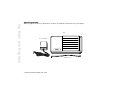
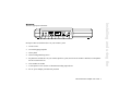
ENHANCED
FEATURE
ADAPTER
User Guide
Venture
Multiline Communications System
Unpacking the EFA ...........................................2
EFA ports .........................................................3
Connecting your EFA to your Venture System ...4
Verify that the EFA is connected to your system.................. 5
Adding a music source .....................................5
Connecting a music source.................................................... 5
Activating Music on hold...................................................... 5
Activating Background music............................................... 6
Adding loudspeaker paging.............................6
Connecting a loudspeaker page amplifier ............................. 6
Activating loudspeaker paging.............................................. 6
Adding the Venture Door Phone .......................6
Connecting your Venture Door Phone .................................. 7
Activating your Venture Door Phone.................................... 7
Setting Door phone options................................................... 7
Adding an electronic door latch ........................8
Connecting your electronic door latch .................................. 8
Enhanced Feature Adapter User Guide i
Contents
Introduction .....................................................1
Contents
Adding a fax machine or modem .................... 8
Connecting your fax machine or modem to your EFA..........9
Activating Fax switch ............................................................9
Adding a Call Detail Recording ........................ 9
Connecting a computer ..........................................................9
Connecting a printer.............................................................10
Activating CDR ...................................................................10
Adding account code capabilities to CDR ........ 11
Password protecting the EFA option settings .. 11
Using EFA functions ....................................... 11
Answering a door phone call ...............................................11
Turning Background music ON or OFF at each Venture phone
12
Using an account code while on a call.................................12
Loudspeaker paging .............................................................13
Saving Background music and Account code to a Memory key
13
Saving Door phone to a Memory key ..................................13
Troubleshooting ............................................ 14
EFA options does not appear in the Services list ...................14
ii Enhanced Feature Adapter User Guide
Appendix.......................................................15
Running cable to the jacks .................................................. 15
Terminating two lines on the EFA ...................................... 16
EFA connection requirements ............................................ 17
Canadian regulatory information ...................19
U.S. regulatory information............................20
Index .............................................................25
Enhanced Feature Adapter User Guide iii
Contents
You forgot your password................................................... 14
Contents
iv Enhanced Feature Adapter User Guide
Congratulations! Adding the
Enhanced Feature Adapter (EFA) to
your Venture system enables you to
connect seven devices: a music
source, an external page amplifier, a
door phone, a door locking/
unlocking device, a fax machine or
modem, and a printer or a PC.
Adding these devices to your
Venture system enables you to:
•
provide music to callers who
have been put on hold
•
play music though the handsfree
speaker of your phone
•
page over a public address
system
•
answer and open a door from a
phone in your Venture system
•
use one line alternately for voice
calls, and for faxes or modem
transmissions
•
accumulate and display Call
Detail Recording (CDR)
accounting information
Installing and using the
Introduction
This User guide explains how to
install the EFA, and to program and
use the EFA options.
☞ Note: Any wiring of your
home or office that may be required
to install the devices connected to
your EFA should be done by
following the instructions that come
with each device. These instructions
are not covered in this EFA User
Guide.
Enhanced Feature Adapter User Guide 1
Installing and using the
Unpacking the EFA
When you unpack the EFA you should have: one EFA, one telephone cord and one AC power adapter.
EFA
AC power adapter
telephone cord
2 Enhanced Feature Adapter User Guide
There are eight ports on the EFA:
1
2
3
4
5
6
7
8
Each port connects a different device to your Venture system:
1.
a music source
2.
an external paging amplifier
3.
a door phone
4.
a door locking/unlocking device
5.
the phone line used as line 1 on your Venture phone or system, and if a fax or modem is attached, a second phone
line to be used for the fax
6.
a fax machine or modem
7.
a serial printer or a PC used as a Call Detail Recording output device
8.
the AC power adapter provided with your EFA
Enhanced Feature Adapter User Guide 3
Installing and using the
EFA ports
Installing and using the
Connecting your EFA to
your Venture System
1.
Plug one end of the 6-wire cord
provided with your EFA into a
phone jack on which the
telephone line, used as line 1 on
your Venture system, is
terminated.
line 1
AC outlet
☞ Note: If the EFA will be
used with a fax machine or
modem, a second line to be used
for the fax or modem line must
also be terminated on this jack.
See “Terminating two lines on
the EFA” on page 16.
2.
Plug the other end of the 6-wire
cord into the telephone
on your EFA.
3.
port
Plug the power adapter cord into
the AC power ! port on your
EFA.
4.
EFA
Plug the power adapter into an
AC outlet.
4 Enhanced Feature Adapter User Guide
telephone port
AC power port
2.
Press £.
3.
Press ’ until your display
shows EFA options. If your
display does not show EFA
options, see “Troubleshooting”
on page 14.
license be obtained for the right
to reproduce or transmit the
music source through the music
on hold or background music
features of this
telecommunications system.
Venture purchasers are solely
responsible for obtaining any
such license(s); in no event will
Northern Telecom or any of its
subsidiaries be liable for a
failure to obtain the required
licenses.
Adding a music source
Adding a music source to your EFA
enables you to:
•
•
provide music to calls on hold
for every telephone line
connected to your Venture
system
play background music through
the handsfree speaker on idle
phones
☞ Note: Depending on your
music source, applicable
copyright law may require that a
Connecting a music source
You will need a cable with a 3.5 mm
earphone jack on one end and
whatever is required to fit the output
of your music source on the other
end. Three typical types of
connectors are:
1.
Plug the cable into the output
(line out) of your music source.
☞ Note:
Do not plug the
cable into the loudspeaker
output of your music source. If
your music source has a separate
amplifier, use the auxiliary, line
out or headphone output jacks.
This could damage both
your EFA and the music
source.
2.
Plug the other end of the cable
into the
3.
port on your EFA.
Turn on the music source.
Activating Music on hold
1. Go to any Venture phone.
2.
Press £.
•
for tape or CD players and tuners
— an RCA jack
3.
Press ’ until your display
shows EFA options.
•
for amplifiers — a 3.5 mm
earphone jack
4.
Press —.
Enhanced Feature Adapter User Guide 5
Installing and using the
Verifying that the EFA is
connected to your system
1. Go to any Venture phone.
Installing and using the
5.
Press ’ until your display
shows Music on hold.
6.
Press ¥ to turn on Music on
hold.
Activating Background music
Activating background music at any
Venture phone makes music
available to all Venture phones on the
system. Background music is then
turned ON or OFF at each phone.
1.
Go to any Venture phone.
2.
Press £.
3.
Press ’ until your display
shows EFA options.
4.
Press —.
5.
Press ’ until your display
shows Music at idle.
6.
Press ¥ to turn on background
music.
6 Enhanced Feature Adapter User Guide
☞ Note: See also, “Turning
1.
Plug one end of the cable into the
input port of your paging
amplifier as shown in the
amplifier instructions.
Adding loudspeaker
paging
2.
Plug the other end of the cable
into the
port on your EFA.
Connecting a loudspeaker paging
amplifier for a public address system
enables you to make loudspeaker
announcements from your Venture
phones.With loudspeaker paging
activated, when you page all phones
from any Venture phone, your
message will be sent out over the
public address system as well as to all
of your Venture phones.
3.
Turn on your external page
amplifier and follow the
manufacturer’s instructions for
selecting the appropriate input.
Background music ON or OFF at
each Venture phone” on page 12.
Connecting a loudspeaker page
amplifier
You will need a cable with a 3.5 mm
earphone jack on one end and
whatever is required to fit the input of
your external page amplifier on the
other end. These are available at most
electronics and audio stores.
Activating loudspeaker paging
1. Go to any Venture phone.
2.
Press £.
3.
Press ’ until your display
shows EFA options.
4.
Press —.
5.
Press ’ until your display
shows Extern page.
6.
Press ¥ to turn on external
paging.
Adding the Venture Door Phone
(Aastra part number: A0665958)
enables you to answer a door from
one or all the phones in your Venture
system.
3.
4.
☞ Note: Only the Venture Door
1.
2.
Follow the instructions included
in your Venture Door phone for
connecting the wires to it.
Strip approximately 1/4 inch of
insulation from the other end of
the wires.
5.
Press ’ until your display
shows Door phone.
6.
Press ¥ to turn on door phone
answering capabilities.
Insert the wires into the two
terminals. It does not matter
which wire goes into which
terminal.
Setting Door phone options
By setting the following options, you
can customize the way your door
phone works.
☞ Note:
To disconnect the
door phone wires from the EFA,
insert a stiff piece of wire (such
as a paper clip) into the slot
above the wire while pulling the
wire out of the terminal.
Phone can be used with your EFA.
Connecting your Venture Door
Phone
You will need a pair of 16 to 20
gauge solid wires such as telephone
wire or doorbell wire. These are
available at most hardware and
building supply stores.
If the wires are stranded, apply
solder to the wires to make them
solid enough to insert into the
EFA terminals.
Activating your Venture Door
Phone
1. Go to any Venture phone.
2.
Press £.
3.
Press ’ until your display
shows EFA options.
4.
Press —.
Door phone name—changes the
door phone name to any 16-character
name you choose.
Door phone ID—changes 98, the ID
assigned to your door phone at the
factory, to any 2-digit number you
choose.
Door timeout—sets the number of
times a phone will ring when the door
phone button is pressed. (The default
is three rings.)
Door calls all/Door calls
phone—sets door phone calls to ring
at all phones or one phone in your
Enhanced Feature Adapter User Guide 7
Installing and using the
Adding the Venture Door
Phone
Installing and using the
system. (Door calls all is the
default setting.)
☞ Note: When Door calls
phone is selected, but the call is not
answered by the selected phone (after
the programmed number of rings),
the door phone call will ring on all
Venture phones.
Phone ID to call—when you select
Door calls phone, Phone ID to
call selects one phone to which all
door phone calls will go.
1.
Go to any Venture phone.
2.
Press £.
3.
Press ’ until your display
shows EFA options.
4.
Press —.
5.
Press ’ until your display
shows the Door phone option
you want to set.
6.
Press ¥ .
8 Enhanced Feature Adapter User Guide
7.
Follow the display prompts.
3.
If the wires are stranded, apply
solder to the wires to make them
solid enough to insert into the
EFA terminals.
4.
Insert the wires into the two
terminals on the EFA. It
does not matter which wire goes
into which terminal.
Adding an electronic door
latch
When you have added the Venture
Door Phone to your system, you can
use an electronic door latch to release
the door lock from your Venture
phones.
Connecting your electronic door
latch
You will need a pair of 16 to 20
gauge solid wires such as telephone
wire or doorbell wire available at
most hardware or building supply
stores.
1.
Follow the door latch
manufacturer’s instructions to
connect one end of the wires in
place of the push button actuator
of the doorlatch.
2.
Strip approximately 1/4 inch of
insulation from the other end of
the wires.
☞ Note:
To disconnect the
door latch wires from the EFA,
insert a stiff piece of wire (such
as a paper clip) into the slot
above the wire while pulling the
wire out of the terminal.
Adding a fax machine or
modem
If you subscribe to the telephone
service provider feature called
Distinctive Ringing, adding a fax
machine or modem to your system
through your EFA will enable you to
use one line alternatively for making
(and receiving) phone calls and for
sending (and receiving) faxes or
3.
☞ Note: On line 2 the distinctive
1.
Go to any Venture phone.
2.
Press £.
3.
Press ’ until your display
shows EFA options.
ring phone number must be assigned
to the fax machine or modem.
☞ Note: Distinctive Ringing may
also be called Ident-a-call, Ident-aring, Teen Service, Smart Ring,
Signal Ring or Custom Ringing.
Connecting your fax machine or
modem to your EFA
1. Plug one end of the phone wire
that comes with your fax or
modem into your fax or modem.
2.
Plug the other end of the phone
wire into the second
your EFA.
port on
Set your fax machine or modem
to answer after 3 or more rings.
Activating Fax switch
This activates the Fax switch feature.
4.
Press —.
5.
Press ’ until your display
shows Fax switch.
6.
Press ¥ to turn Fax switch on.
☞ Note: The distinctive ring
line assigned to the Fax switch
rings at all Venture phones.
Adding a Call Detail
Recording
Connecting a printer or computer
with Call Detail Recording (CDR)
software to your system through your
EFA, provides accounting
information on all incoming and
outgoing calls except for calls less
than five seconds long, unanswered
calls and intercom calls. You can also
to enter an up to 4- digit account code
during a call so that you can track
calls for a specific customer or
account.
Your EFA requires:
•
a serial printer set at 9600 baud
with a minimum of 40 columns.
OR
•
a computer with Call Detail
Accounting software package
that accepts SL-1 records.
☞ Note: Your CDR printer will
record all numbers dialed including
passwords. Ensure that the
printer or computer is located
where this information can
remain confidential.
Enhanced Feature Adapter User Guide 9
Installing and using the
modem transmissions. The line used
for both the fax or modem calls and
phone calls must be wired as line 2 in
the phone jack that you plug your
EFA into.
Installing and using the
Connecting a computer
You will need a 9-pin serial cable. In
addition, if your computer uses a 25pin connector for its serial port, you
need a 9-pin to 25-pin adapter. These
are available at any computer store.
1.
Plug one end of the serial cable
into your computer.
2.
Plug the other end of the serial
cable into your
EFA.
3.
port on your
Follow the instructions that
came with your software to
configure your computer for the
following serial format:
•
9600 baud
•
8 data bits
•
No parity
•
1 stop bit
Connecting a printer
To connect a printer, you will need a
9-pin null modem adapter and a 9-pin
serial cable. In addition, if your
printer uses a 25-pin connector for its
serial port, you will also require a 9pin to 25-pin adapter. These are
available at any computer store.
☞ Note: The Scriptos
Technologies serial printer. No. 550
0102 02 103 is an example of a serial
printer that works with the Venture
EFA.
1.
2.
3.
10 Enhanced Feature Adapter User Guide
Plug the null modem adapter
into either end of your 9-pin
cable.
Plug either end of the 9-pin cable
into your printer.
4.
Follow the instructions that
came with your printer to
configure your printer for the
following serial format:
•
9600 baud
•
8 data bits
•
No parity
•
1 stop bit
Activating CDR
Activating CDR includes turning on
CDR, turning on Account code and
selecting on of these four CDR
output formats:
•
CDR in English—a printer
format used to print call
records in English
•
CDR in French—a printer
format used to print call
records in French
•
CDR in Spanish—a printer
format used to print call
records in Spanish
Plug the other end of the 9-pin
cable into your
EFA.
port on your
CDR as SL-1 data—a
computer format used by
call detail accounting
software
1.
Go to any Venture phone.
2.
Press £.
3.
Press ’ until your display
shows EFA options.
4.
Press —.
5.
Press ’ until your display
shows CDR OFF.
6.
Press ¥ to turn CDR on.
7.
Press ’ until your display
shows Account code OFF.
8.
Press ¥ to turn Account code
on.
9.
Press ’ until your display
shows
CDR in English
’=next *=change.
10. If CDR in English is your
preference, press ™ to
exit the list or press ’ to go to
the next EFA option.
OR
If you want a different CDR
format, press ¥ and go on to
step 11.
1.
Go to any Venture phone.
2.
Press £.
3.
Press ’ until your display
shows EFA options.
4.
Press —.
5.
Press ’ until your display
shows Password.
6.
Press ¥ .
7.
Follow the prompts to enter the
4-digit password.
Using EFA functions
11. Press ’ until your display
shows the format you want.
The following EFA functions are
activated at each Venture phone:
12. Press ¥ . Your display shows
the option you selected and
- confirmed -.
☞ Note: Account code ON
Password protecting the
EFA option settings
enables you to enter a 4-digit
code during a call so that you can
track calls for a specific
customer or account.
When a 4-digit password is used, you
can limit access to the EFA options
sublist in the Services list to those
who know the password.
•
answering door phone calls
•
turning background music on
and off
•
adding account code
information for individual phone
calls to CDR records
•
paging
Enhanced Feature Adapter User Guide 11
Installing and using the
•
Installing and using the
Answering a door phone call
When you have activated the door
phone option on your Venture phone
and the door phone rings, your
display shows Door phone calling.
phone). To answer the door, go to the
door.
1.
Pick up the handset or press
handsfree/mute key.
☞ Note: If you are using your
2.
Press Û.
OR
If you have saved Background
music to a memory key, press
the memory key twice.
3.
Press ’ until your display
shows Door phone.
☞ Note:
4.
Press —.
5.
Speak to the person at the door.
6.
If you have a door unlocking
device and want to open the
door, press ¥ to open the door.
intercom line, when a door phone call
is received, you must release your
ongoing intercom call to answer the
incoming door phone call.
☞ Note: When Door calls
phone is selected, but the call is not
answered by the selected phone (after
the programmed number of rings),
the door phone call will ring on all of
your Venture phones.
☞ Note: If all the intercom paths
Turning Background music ON
or OFF at each Venture phone
1. Press £.
2.
are busy when a door phone call
comes in, your display shows the
Door phone, 98 (or any other 2-digit
ID you have assigned to the door
12 Enhanced Feature Adapter User Guide
Press ’ until your display
shows Background music.
☞ Note: Background music
must be activated for this
message to be displayed.
3.
1.
Press — turn Background music
on.
See “Saving
Background music and Account
code to a Memory key” on
page 13.
☞ Note: You can adjust the
volume of music through the
speaker when it is playing:
•
press the right end of the
¶ to
increase the volume.
OR
• press the left end of the
¶ to
decrease the volume.
2.
Press £.
3.
Press ’ until your display
shows Account code.
4.
Press —.
5.
Enter a 1 to 4-digit account code.
OR
☞ Note: When more than
one phone is included in a call,
the account code record lists
only the phone that made or
answered the call.
☞ Note: When an account
code is entered during a
conference call, it overrides any
previously entered account code.
1.
If you have saved account code
to a memory key, make or
answer a call.
display shows Background
music or Account code in your
Services list.
2.
Press the memory key.
3.
Press —.
4.
Enter a 1 to 4-digit account code.
3.
Press ß. The display
shows Save to?
4.
Press the memory key that you
want to use.
5.
Follow the display prompts.
☞ Note:
See “Saving
Background music and Account
code to a Memory key” on
page 13.
Loudspeaker paging
When the Extern page option is set
to ON, when you page all phones on
your Venture system, your page is
also broadcast over your public
address system.
Saving Background music and
Account code to a Memory key
Background music and Account code
EFA options are stored in the Services list
as services once they have been
programmed. From the Services list they
can be saved to a memory key.
1.
Press £.
2.
Press ” or ’, until your
Saving Door phone to a Memory
key
When the Door phone option is activated,
the Door phone is listed in your Phone list
and your Directory. From the Phone list
or the Directory, it can be saved to a
memory key.
1.
Press ’ until your display
shows Door phone.
2.
Press ß. Your display
shows Save to?
3.
Press the memory key that you
want to use. The display shows
Saved: Memory key
Door phone.
Enhanced Feature Adapter User Guide 13
Installing and using the
Using an account code while on
a call
1. Make or answer a call.
Troubleshooting
Troubleshooting
Troubleshooting is required when
you install your EFA and EFA
options does not appear in the
Services list or when you forget
your password.
5.
Pick up the handset. You should
hear dial tone.
6.
Check on a Venture phone to
ensure that the „
indicator light is lit.
7.
If there is no dial tone, or the
phone’s „ indicator
light is not lit, verify that the
phone jack is wired correctly,
see “Terminating two lines on
the EFA” on page 16.
EFA options does not appear in
the Services list
1. Ensure that there are 3 spaces
available in your Services list to
display Background music,
Account code and EFA options.
8.
If line one has dial tone and the
indicator light is lit, reconnect
your EFA.
9.
If EFA options is still not
available in the Services list,
open the Termination Module
included with your EFA and
follow the instructions included
with it.
☞ Note: The Services list
has a total of 20 spaces. To free
up spaces in your Services list
you can delete services or save
services to your memory keys.
2.
Ensure that your EFA is plugged
into a live AC outlet.
3.
If the problem persists, unplug
your EFA from the phone jack.
4.
Plug in a phone.
10. If problems persist call the
Aastra help desk at
1-800-574-1611.
14 Enhanced Feature Adapter User Guide
You forgot your password
You can’t enter the EFA options list
because you have forgotten the
password.
1.
Press £.
2.
Press ’ until your display
shows EFA options.
3.
Press —. The display reads
Please enter Password >.
4.
Enter the month, date and hour
(in 24 hour format) displayed on
the phone.
If your phone is displaying
FEB 21 3:45pm, the password
would be 022115.
5.
Press ’ repeatedly until your
display shows Password.
6.
Press ¥ . The display shows
your 4-digit password.
This appendix provides in-depth
information required to complete the
wiring of a Venture EFA, from the
connecting blocks to a Venture EFA.
It is intended for use by installers or
individuals with system wiring
experience.
and the telephones (a home run
configuration) is recommended.
☞ Note: In a home run
configuration a separate cable is
run from the connecting block to
each telephone and from the
connecting block to the EFA.
Running cable to the jacks
When wiring is required for new
installations or to provide additional
phone lines:
•
A separate jack is required for
the EFA.
•
The same telephone line must
appear as line 1 on each Venture
phone and the EFA so that the
EFA will appear in the Services
list of each phone.
•
Three (or more) twisted-pair
cable is recommended.
•
Running cable from the
connecting blocks to the EFA
Enhanced Feature Adapter User Guide 15
Appendix
Appendix
Appendix
Terminating two lines on the EFA
This is required when a fax machine
or a modem will be sharing a
telephone line with a phone in your
system.
1.
Connect phone line 1 to the red
and green pins of the phone jack
2.
Connect phone line 2 to the
black and yellow pins of the first
phone jack.
3.
Plug one end of the telephone
cord provided with the EFA into
the phone jack.
4.
connecting block
line 1
line 2
red
green
black
yellow
Plug the other end of the
telephone cord into the phone
port on the EFA.
telephone cord
16 Enhanced Feature Adapter User Guide
EFA
Device
Music source (CD player, radio
etc.)
Port
ICON
Type of connector required and acceptable levels of input or
output and device impedance
3.5 mm mini jack connector (output appears on left channel of a stereo jack
only)
Input level of -20dBVrms to +6dBVrms
Input impedance is 5 Kohms
External page amplifier
3.5 mm mini jack connector, (output appears on both the left and right channels)
Output impedance is 600 ohms. Output level is -14 dbVrms open circuit (-20
dbVrms into 600 ohms).
Venture door phone
Push-in type connector suitable for AWG 16 to AWG 20 solid or tinned stranded wire
The Venture door phone is the only door phone that can be attached to the EFA.
The Aastra part number for ordering a door phone is AO665958.
Door lock/unlock interface
(A normally open relay contact
used to control a door latch solenoid or similar device.)
Push-in type connector suitable for AWG 16 to AWG 20 solid or tinned stranded wire
Rating of relay contacts;1 Amp at 30 Vdc, 0.3 Amp at 110 Vdc, 0.5 Amp at
125 Vdc
Enhanced Feature Adapter User Guide 17
Appendix
EFA connection requirements
The following table shows the ICON for the port to which the device should be connected, the type of connector
required, the acceptable level of input and output and impedance for each device connected to the EFA.
Appendix
The telephone line used as line 1
on the Venture phone(s) and a
second telephone line used for
the fax machine.
RJ12 jack. (This cord is provided with the EFA.)
Fax machine or modem
RJ12 jack. (The Venture EFA is configured so the fax or modem line appears
on pins 3 and 4 of jack number 2.)
Printer or computer
DB9 connector.
To connect a printer a null modem is also required.
To connect a computer with a 25-pin serial port connector a 9-pin to 25-pin
adapter is also required.
AC power
The AC adapter is included with your EFA.
!
18 Enhanced Feature Adapter User Guide
16 Vrms, 50/60 Hz, 500 ma
be connected to customer provided jacks
except where specified by individual
telecommunications company tariffs.
Industry Canada Notice
The Industry Canada label identifies certified
equipment. This certification means that the
equipment meets certain telecommunications
network protective, operational and safety
requirements. The Department does not
guarantee the equipment will operate to the
user’s satisfaction.
Repairs to certified equipment should be made
by an authorized Canadian maintenance
facility designated by the supplier. Any repairs
or alterations made by the user to this
equipment, or equipment malfunctions, may
give the telecommunications company cause
to request the user to disconnect the
equipment.
Before installing this equipment, users should
ensure that it is permissible to be connected to
the facilities of the local telecommunications
company. The equipment must also be
installed using an acceptable method of
connection. The method of connection
approved for this equipment as designated by
D.O.C. Standard CS-03 is a CA11A/CA14A
or CA11W/CA14W connection arrangement.
The A or W suffix indicates that either desk or
wall mounting is approved. In some cases, the
company’s inside wiring associated with a
single line individual service may be extended
by means of a certified jack-plug-cord
ensemble (telephone extension cord). The
customer should be aware that compliance
with the above conditions may not prevent
degradation of service in some situations.
Users should ensure for their own protection
that the electrical ground connections of the
power utility, telephone lines and internal
metallic water pipe system, if present, are
connected together.
Existing telecommunications company
requirements do not permit their equipment to
only to the requirement that the sum of the LN
of all the devices does not exceed 100.
This telephone has been tested and found to
comply with the limits for a Class B digital
device in accordance with the Canadian EMI
requirement ICES-003.
CAUTION: To eliminate the possibility of
accidental damage to cords, plugs, jacks and
the telephone, do not use sharp instruments
during the assembly procedures.
WARNING: Do not insert the plug at the
free end of the receiver cord directly into a
wall or baseboard jack. Such misuse can result
in unsafe sound levels.
This precaution may be particularly important
in rural areas.
CAUTION: Users should not attempt to make
electrical ground connections themselves, but
should contact the appropriate electric
inspection authority, or electrician, as
appropriate.
NOTICE: The Load Number (LN) assigned to
each terminal device denotes the percentage of
the total load to be connected to a telephone
loop which is used by the device, to prevent
overloading. The termination of a loop may
consist of any combination of devices subject
The exclamation point within
an equilateral triangle is
intended to alert the user to the
presence of important operating and maintenance (serving)
instruction in the literature
accompanying the product.
This symbol on the product is also used to
identify the following important information:
Shock Hazard Warning:
To avoid potential electrical shock hazard to
personnel or damage to the telephone, use only
the manufacturer supplied equipment and
installation procedures. Specifically, use only
6 conductor modular Teladapt plug/cords with
Enhanced Feature Adapter User Guide 19
Regulator y infor mation
Canadian regulatory
information
Regulator y infor mation
this product, and the AC transformer must be
CSA/UL or CSA-NRTL/C approved Class 2,
level C, rated as follows:
For North American Markets mains nominal
AC voltage 110-117V:
For Venture EFA- Input: 117/120VAC, 50/
60Hz, 12W and Output: 16VAC 500 mA.
For International Markets mains nominal AC
voltage 220-240V:
For Venture EFA- Input: 220/240VAC, 50/
60Hz, 12W and Output: 16VAC 500 mA.
Substitution of non approved equipment will
void the Aastra warranty.
designed to provide reasonable protection,
there is no guarantee that interference will not
occur in a particular installation. You can
determine whether interference occurs by
monitoring your radio or television reception
while placing a call.
If your terminal causes interference, one of the
following measures may correct the problem:
Reorient or relocate the receiving TV or radio
antenna, where this may be done safely.
To the extent possible, move the telephone and
the radio or television farther away from each
other, or connect the telephone and the radio or
television to outlets on separate circuits.
Consult the dealer or an experienced radio/
television technician for additional
suggestions.
U.S. regulatory information
Radio/TV interference
Terminals equipped with electronic push-key
dials generate and use radio frequency energy,
and if not installed and used properly and in
strict accordance with the manufacturer’s
instructions, may cause interference to radio
and television reception. These terminals have
been tested and found to comply with the
limits for a Class B digital device in
accordance with the specifications in Part 15
of the FCC rules. While these rules are
Federal Communications Commission
(FCC) notice
FCC registration number: This telephone
equipment complies with Part 68, Rules and
Regulations, of the FCC for direct connection
to the Public Switched Telephone Network.
(The FCC registration number appears on a
sticker affixed to the bottom of the telephone.)
Note: FCC registration does not constitute an
expressed or implied guarantee of
performance.
20 Enhanced Feature Adapter User Guide
Your connection to the telephone line must
comply with these FCC rules:
Use only an FCC standard RJ11W/RJ14W or
RJ11C/RJ14C network interface jack and FCC
compliant line cord and plug to connect this
telephone to the telephone line. (To connect
the telephone, press the small plastic tab on the
plug at the end of the telephone’s line cord.
Insert into a wall or baseboard jack until it
clicks. To disconnect, press the tab and pull
out.)
If a network interface jack is not already
installed in your location, you can order one
from your telephone company. Order RJ11W/
RJ14W for wall-mounted telephones or
RJ11C/RJ14C for desk/table use. In some
states, customers are permitted to install their
own jacks.
Your telephone may not be connected to a
party line or coin telephone line. Connection to
Party Line Service is subject to state tariffs.
(Contact the state public utility commission,
public service commission or corporation
commission for information.)
It is no longer necessary to notify the
Telephone Company of your phone’s
Registration and REN numbers. However, you
must provide this information to the telephone
company if they request it.
The telephone company may make changes in
its facilities, equipment, operations or
procedures that could affect the operation of
the equipment. If this happens the telephone
company will provide advance notice in order
for you to make necessary modification to
maintain uninterrupted service.
Do not attempt to repair this equipment
yourself. If trouble is experienced with this
equipment, for repair or warranty information
please contact 1-800-574-1611
If the equipment is causing harm to the
telephone network, the telephone company
may request that you disconnect the equipment
until the problem is resolved.
Signaling method: The unit’s push-key
dial allows it to signal in tones (DTMF). It can
complete calls to local and long distance lines
and can also complete long distance calls via
computer-phone systems such as MCI or
SPRINT.
CSA-NRTL/C installation
instructions
Ringer Equivalence Number: The FCC
Registration label (on bottom of phone),
includes a Ringer Equivalence Number
(REN), which is used to determine the number
of devices you may connect to your phone line.
A high total REN may prevent phones from
ringing in response to an incoming call and
may make placing calls difficult. In most
areas, a total REN of 5 should permit normal
phone operation. To determine the total REN
allowed on your telephone line, consult your
local telephone company.
Warning: Avoid electrical shock hazard to
personnel or equipment damage observe the
following precautions when installing
telephone equipment:
Hearing aids: The telephone is compatible
with hearing aids equipped with an appropriate
telecoil option and is compliant with the
requirements for hearing aid compatibility of
the Americans with Disabilities Act (ADA).
Programming emergency numbers: When
programming emergency numbers and/or
making test calls to emergency numbers:
1. Check with local authorities before making
any test calls to emergency numbers.
2. Remain on the line and briefly explain to the
dispatcher the reason for calling before
hanging up.
3. Perform such activities in the off-peak
hours, such as early mornings or late evenings.
1. Never install telephone wiring during a
lightning storm.
2. Never install telephone jacks in wet
locations unless the jack is specifically
designed for wet locations.
3. Never touch uninsulated telephone wires or
terminals unless the telephone line has been
disconnected at the network interface.
4. Use caution when installing or modifying
telephone lines.
Important safety instructions
When using your telephone equipment, basic
safety precautions should always be followed
to reduce risk of fire, electric shock and injury
to persons, including the following:
1. Read and understand all instructions.
2. Follow the warnings and instructions
marked on the product.
3. Unplug this product from the wall outlet
before cleaning. Do not use liquid cleaners or
Enhanced Feature Adapter User Guide 21
Regulator y infor mation
If this terminal equipment causes harm to the
telephone network, the telephone company
will notify you in advance that temporary
discontinuance of service may be required. If
advance notice isn’t practical, the telephone
company will notify the customer as soon as
possible. Also, you will be advised of your
right to file a complaint with the FCC if you
believe it necessary.
Regulator y infor mation
aerosol cleaners. Use a damp cloth for
cleaning.
(A) When the power supply cord or plug is
damaged or frayed.
4. Do not use this product near water, for
example, near a bath tub, wash bowl, kitchen
sink, or laundry tub, in a wet basement, or near
a swimming pool.
(B) If the product has been exposed to rain,
water or liquid has been spilled on the product,
disconnect and allow the product to dry out to
see if it still operates; but do not open up the
product.
5. Do not place this product on an unstable
cart, stand or table. The product may fall,
causing serious damage to the product.
6. This product should never be placed near or
over a radiator or heat register. This product
should not be placed in a built-in installation
unless proper ventilation is provided.
(D) If the product exhibits a distinct change in
performance.
12. Avoid using a telephone during an
electrical storm. There may be a remote risk of
electric shock from lightning.
13. Do not use the telephone to report a gas
leak in the vicinity of the leak.
8. Do not overload wall outlets and extension
cords as this can result in the risk of fire or
electric shock.
14. CAUTION: To eliminate the possibility
of accidental damage to cords, plugs, jacks,
and the telephone, do not use sharp
instruments during the assembly procedures.
10. To reduce the risk of electric shock do not
disassemble this product, but have it sent to a
qualified service person when some service or
repair work is required.
The exclamation point within an
equilateral triangle is intended to
alert the user to the presence of
important operating and
maintenance (serving) instruction
in the literature accompanying
the product..
(C) If the product housing has been damaged.
7. Do not allow anything to rest on the power
cord. Do not locate this product where the cord
will be abused by persons walking on it.
9. Never spill liquid of any kind on the
product.
16. Save these instructions.
15. WARNING: Do not insert the plug at the
free end of the handset cord directly into a wall
or baseboard jack. Such misuse can result in
unsafe sound levels or possible damage to the
handset.
11. Unplug this product from the wall outlet
and refer servicing to qualified service
personnel under the following conditions:
22 Enhanced Feature Adapter User Guide
This symbol on the product is used to identify
the following important information:
Shock Hazard Warning:
To avoid potential electrical shock hazard to
personnel or damage to the telephone, use only
the manufacturer supplied equipment and
installation procedures. Specifically, use only
6 conductor modular Teladapt plug/cords with
this product, and the AC transformer must be
CSA/UL or CSA-NRTL/C approved Class 2,
level C, rated as follows:
For North American Markets mains nominal
AC voltage 110-117V:
For Venture EFA- Input: 117/120VAC, 50/
60Hz, 12W and Output: 16VAC 500 mA.
For International Markets mains nominal AC
voltage 220-240V:
For Venture EFA- Input: 220/240VAC, 50/
60Hz, 12W and Output: 16VAC 500 mA.
Warranty and repair
If you have several telephones and you are
having problems with all of them, or if your
telephone works in some outlets and not in
others, your problem may originate with the
local telephone lines or with central office
equipment. Contact your telephone company
repair service listed in the front of your phone
book.
Should the terminal fail during the twelve
month warranty period, please return it for
repair to the manufacturer, or to the authorized
agent as specified in the product literature.
You will be responsible for shipping charges,
if any, and for presenting proof of your
telephone’s date of purchase.
If the terminal is covered by a Telephone
Company Maintenance Agreement, follow the
procedure set forth in the Maintenance
Agreement for obtaining repair or replacement
of the terminal.
If the terminal is no longer covered by the
manufacturer or its authorized agents’
Warranty, and is not covered by a Telephone
Company Maintenance Agreement, you may
return the terminal to the manufacturer or its
authorized agents for repair or refurbishment.
You will be billed for any repairs.
Repair to this equipment can only be made by
Aastra Telecom Inc. and its authorized agents,
and by others who may be authorized by the
FCC. Questions about the warranty or requests
for the manufacturer’s policy and procedure
on repair and refurbishment should be directed
to the manufacturer or authorized agent as
specified in the product literature.
Manufacturer’s limited twelve month
warranty
Coverage: The manufacturer warrants this
terminal against defects and malfunctions for a
period of twelve months from the date of
original purchase. If there is a defect or
malfunction, Aastra Telecom Inc. or its
authorized agents will, at its option, and as the
exclusive remedy, either repair or replace the
terminal at no charge if returned within the
warranty period.
If replacement parts are used during repair,
these parts may be refurbished or may contain
refurbished materials. If it is necessary to
replace the terminal, it may be replaced with a
refurbished terminal of the same design and
color. If it should become necessary to repair
or replace a defective or malfunctioning
terminal set under this warranty, the provisions
of this warranty shall apply to the repaired or
replaced terminal until the expiration of ninety
(90) days from the date of pick-up, or the date
of shipment to you of the repaired or
replacement set or until the end of the original
twelve month warranty period whichever is
later.
Exclusions: Aastra Telecom Inc. does not
warranty this terminal to be compatible with
the equipment of any particular telephone
company. This warranty does not extend to
damage to product resulting from improper
installation or operation, alteration, neglect,
abuse, misuse, fire or natural causes such as
storms or floods after the terminal is in your
possession.
Aastra Telecom shall not be liable for any
incidental or consequential damages,
including but not limited to loss, damage, or
expense directly or indirectly arising from the
customer’s use or inability to use this product,
either separately or in combination with other
equipment. This paragraph, however, shall not
apply to consequential damages for injury to
the person in the case of telephones used or
bought for use primarily for personal, family,
or household purposes.
The warranty sets forth the entire liability and
obligations of Aastra Telecom Inc. and its
authorized agents with respect to breach of
warranty, and the warranties set forth or
limited herein are the sole warranties and are in
lieu of all other warranties, expressed or
implied, including warranties or fitness for
particular purpose and merchantability.
Enhanced Feature Adapter User Guide 23
Regulator y infor mation
Substitution of non approved equipment will
void the Aastra warranty.
Regulator y infor mation
State law provisions: This warranty gives you
specific legal rights and you may have other
rights which vary from state to state. Some
states do not allow the exclusion of incidental
or consequential damages or allow limitation
on implied warranties or their duration, so that
above exclusions or limitations may not apply.
24 Enhanced Feature Adapter User Guide
B
background music 6
at each Venture phone 12
C
Call Detail Recording
activating CDR 10
adding 9
connecting a printer 10
Canadian regulatory
information 19
CDR (see Call Detail
Recording) 10
CDR printer location 9
connecting
computer 10
EFA to your system 4
electronic door latch 8
fax machine or modem 8
loudspeaker page amplifier
6
music source 5
D
Distinctive Ringing 8
Door phone 7
E
EFA connection requirements
17
EFA options not in Services
list 14
EFA ports 3
electronic door latch 8
F
fax machine
connecting 9
Fax switch
activating 9
H
home run 15
M
modem
connecting 9
music at idle 5
music on hold 5
P
password protecting
EFA option settings 11
peripheral device wiring 1
ports, connections 3
Enhanced Feature Adapter User Guide 25
Index
A
account code
using 13
activating
background music 6
CDR 10
Door Phone 7
Fax switch 9
loudspeaker paging 6
music on hold 5
adding
Call Detail Recording 9
electronic door latch 8
fax machine or modem 8
loudspeaker paging 6
music source 5
answering a door phone call 12
Index
printers, compatible 10
R
regulatory information
Canadian 19
U.S. 20
running cable to the jacks 15
EFA functions 11
V
Venture Door Phone 6
connecting 7
S
saving to a memory key
Account code 13
Background music 13
Door phone 13
setting
Door phone options 7
T
Troubleshooting 14
twisted-pair cable 15
U
U.S. regulatory information 20
unpacking the EFA 2
using
account code 13
26 Enhanced Feature Adapter User Guide