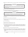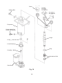
1
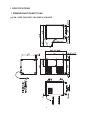
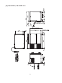
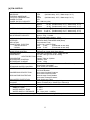
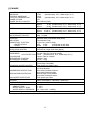
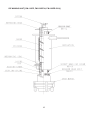
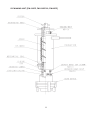
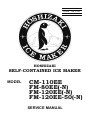
NO.
E2EB-679
ISSUED: JUN. 3, 2005
REVISED: APR. 20, 2011
HOSHIZAKI
SELF-CONTAINED ICE MAKER
CM-110EE
FM-80EE(-N)
FM-120EE(-N)
FM-120EE-50(-N)
MODEL
SERVICE MANUAL
CONTENTS
PAGE
I. SPECIFICATIONS--------------------------------------------------------------------------------------1
1. DIMENSIONS/CONNECTIONS-----------------------------------------------------------------1
[a] CM-110EE, FM-120EE, FM-120EE-N, FM-80EE---------------------------------------1
[b] FM-120EE-50, FM-120EE-50-N-------------------------------------------------------------2
2. SPECIFICATIONS-----------------------------------------------------------------------------------3
[a] CM-110EE----------------------------------------------------------------------------------------3
[b] FM-120EE-----------------------------------------------------------------------------------------4
[c] FM-120EE-N--------------------------------------------------------------------------------------5
[d] FM-120EE-50------------------------------------------------------------------------------------6
[e] FM-120EE-50-N---------------------------------------------------------------------------------7
[f] FM-80EE -----------------------------------------------------------------------------------------8
II. GENERAL INFORMATION--------------------------------------------------------------------------9
1. CONSTRUCTION-----------------------------------------------------------------------------------9
2. OPERATION - How it works-------------------------------------------------------------------- 12
3. TIMER BOARD------------------------------------------------------------------------------------- 13
[a] SOLID-STATE CONTROL------------------------------------------------------------------ 13
[b] TIMER BOARD-------------------------------------------------------------------------------- 13
[c] SEQUENCE------------------------------------------------------------------------------------ 14
III. INSTALLATION INSTRUCTIONS--------------------------------------------------------------- 17
1. UNPACKING---------------------------------------------------------------------------------------- 17
2. LOCATION------------------------------------------------------------------------------------------ 18
3. INSTALLATION------------------------------------------------------------------------------------ 19
4. ELECTRICAL CONNECTIONS---------------------------------------------------------------- 19
5. WATER SUPPLY AND DRAIN CONNECTIONS------------------------------------------ 20
IV. OPERATING INSTRUCTIONS------------------------------------------------------------------ 22
1. START UP------------------------------------------------------------------------------------------- 23
2. PREPARING THE ICEMAKER FOR LONG STORAGE--------------------------------- 24
V. MAINTENANCE AND INSPECTION------------------------------------------------------------ 24
1. PERIODICAL CLEANING----------------------------------------------------------------------- 25
2. CLEANING OF WATER SYSTEM------------------------------------------------------------ 26
3. INSPECTION--------------------------------------------------------------------------------------- 31
[a] EXTRUDING HEAD (UPPER BEARING), HOUSING (LOWER BEARING)--- 31
[b] MECHANICAL SEAL------------------------------------------------------------------------- 31
[c] GEAR MOTOR--------------------------------------------------------------------------------- 32
[d] CONDENSER---------------------------------------------------------------------------------- 32
VI. TECHNICAL INFORMATION--------------------------------------------------------------------- 33
1. WATER CIRCUIT AND REFRIGERANT CIRCUIT---------------------------------------- 33
2. WIRING DIAGRAM------------------------------------------------------------------------------- 34
[a] CM-110EE, FM-120EE(-N), FM-120EE-50(-N)---------------------------------------- 34
[b] FM-80EE---------------------------------------------------------------------------------------- 35
i
3. TIMING CHART------------------------------------------------------------------------------------ 36
[a] PRINCIPLE OF OPERATION-------------------------------------------------------------- 36
[b] PROTECTORS-------------------------------------------------------------------------------- 36
4. PERFORMANCE DATA-------------------------------------------------------------------------- 38
[a] CM-110EE-------------------------------------------------------------------------------------- 38
[b] FM-120EE, FM-120EE-50------------------------------------------------------------------ 39
[c] FM-120EE-N, FM-120EE-50-N------------------------------------------------------------ 40
[d] FM-80EE---------------------------------------------------------------------------------------- 41
VII. SERVICE DIAGNOSIS---------------------------------------------------------------------------- 42
1. NO ICE PRODUCTION-------------------------------------------------------------------------- 42
2. LOW ICE PRODUCTION------------------------------------------------------------------------ 44
3. OTHERS--------------------------------------------------------------------------------------------- 44
VIII. REMOVAL AND REPLACEMENT OF COMPONENTS--------------------------------- 46
1. SERVICE FOR REFRIGERANT LINES----------------------------------------------------- 46
[a] SERVICE INFORMATION------------------------------------------------------------------ 46
[b] REFRIGERANT RECOVERY-------------------------------------------------------------- 47
[c] EVACUATION AND RECHARGE--------------------------------------------------------- 47
2. BRAZING-------------------------------------------------------------------------------------------- 48
3. COMPRESSOR------------------------------------------------------------------------------------ 48
4. DRIER------------------------------------------------------------------------------------------------ 50
5. EXPANSION VALVE------------------------------------------------------------------------------ 51
6. EVAPORATOR ASSEMBLY-------------------------------------------------------------------- 52
7. FAN MOTOR---------------------------------------------------------------------------------------- 56
8. FLOAT SWITCH----------------------------------------------------------------------------------- 56
9. CONTROL WATER VALVE--------------------------------------------------------------------- 57
ii
I. SPECIFICATIONS
1.DIMENSIONS/CONNECTIONS
[a] FM-80EE,FM-120EE, FM-120EE-N,CM-110EE
I. SPECIFICATIONS
1. DIMENSIONS/CONNECTIONS
[a] CM-110EE, FM-120EE, FM-120EE-N, FM-80EE
1
[b] FM-120EE-50,FM-120EE-50-N
[b] FM-120EE-50, FM-120EE-50-N
2
2. SPECIFICATIONS
[a] CM-110EE
AC SUPPLY VOLTAGE
AMPERAGE
STARTING AMPERAGE
ELECTRIC CONSUMPTION
POWER FACTOR
POWER SUPPLY CAPACITY
ICE PRODUCTION PER 24h
1 phase 220-240V
50Hz
3.5A
(Ambient temp. 32°C, Water temp. 21°C)
13A
525W
(Ambient temp. 32°C, Water temp. 21°C)
65%
Min 1.08kVA (4.5A)
Approx.
110 kg (Ambient temp. 10°C, Water temp. 10°C)
Approx.
98 kg (Ambient temp. 21°C, Water temp. 15°C)
Approx.
75 kg (Ambient temp. 32°C, Water temp. 21°C)
WATER CONSUMPTION PER 24h
Approx. 0.110 m3 (Ambient temp. 10°C, Water temp. 10°C)
Approx. 0.098 m3 (Ambient temp. 21°C, Water temp. 15°C)
Approx. 0.075 m3 (Ambient temp. 32°C, Water temp. 21°C)
SHAPE OF ICE
Cubelet
MAX STORAGE CAPACITY
Approx. 32kg - Leveled
(Bin Control Setting Approx. 27kg)
DIMENSIONS (DRAWING No.)
640(W) x 600(D) x 800(H) (mm) (359551)
EXTERIOR
Stainless Steel, Galvanized Steel (Rear)
INSULATION
Polyurethane Foam
CONNECTION - ELECTRIC
Y-type Con. (with EU Plug)
- WATER SUPPLY
Inlet
G 3/4”
(Connected at rear side)
- DRAIN
Outlet R 3/4”
(Connected at rear side)
ICE MAKING SYSTEM
Auger type
HARVESTING SYSTEM
Direct driven Auger (80W Gear Motor)
COMPRESSOR
Hermetic Compressor 315W Model SC12G
CONDENSER
Fin and Tube type forced air cooling
HEAT REJECTION 1030W
EVAPORATOR
Copper Tube on Cylinder
REFRIGERANT CONTROL
Capillary Tube
REFRIGERANT CHARGE
R134a 150g
BIN CONTROL SYSTEM
Mechanical Bin Control (or Actuator and Reed Switch)
(Time Delay Controlled)
ICE MAKING WATER CONTROL
Float Switch and Water Valve
ELECTRICAL PROTECTION
Class I Appliance
6A Circuit Breaker
COMPRESSOR PROTECTION
Auto-reset Overload Protector
Auto-reset Pressure Switch
GEAR MOTOR PROTECTION
Manual-reset Circuit Breaker
Auto-reset Thermal Protector
LOW WATER PROTECTION
Float Switch and Timer
WEIGHT
Net weight 71kg / Gross weight 82 kg
PACKAGE
Carton 746mm(W) x 706mm(D) x 922mm(H)
ACCESSORIES
Scoop, Installation Kit
OPERATION CONDITIONS
AMBIENT TEMP.
5 - 40°C
WATER SUPPLY TEMP
5 - 35°C
WATER SUPPLY PRESSURE
0.5 - 8 bar (0.05 - 0.8MPa)
We reserve the right to make changes in specifications and design without prior notice.
3
[b] FM-120EE
AC SUPPLY VOLTAGE
AMPERAGE
STARTING AMPERAGE
ELECTRIC CONSUMPTION
POWER FACTOR
POWER SUPPLY CAPACITY
ICE PRODUCTION PER 24h
1 phase 220-240V
50Hz
3.5A
(Ambient temp. 32°C, Water temp. 21°C)
13A
520W
(Ambient temp. 32°C, Water temp. 21°C)
65%
Min 1.08kVA (4.5A)
Approx.
125 kg (Ambient temp. 10°C, Water temp. 10°C)
Approx.
115 kg (Ambient temp. 21°C, Water temp. 15°C)
Approx.
85 kg (Ambient temp. 32°C, Water temp. 21°C)
WATER CONSUMPTION PER 24h
Approx. 0.125 m3 (Ambient temp. 10°C, Water temp. 10°C)
Approx. 0.115 m3 (Ambient temp. 21°C, Water temp. 15°C)
Approx. 0.085 m3 (Ambient temp. 32°C, Water temp. 21°C)
SHAPE OF ICE
Flake
MAX STORAGE CAPACITY
Approx. 26kg - Leveled
(Bin Control Setting Approx. 21kg)
DIMENSIONS (DRAWING No.)
640(W) x 600(D) x 800(H) (mm) (359549)
EXTERIOR
Stainless Steel, Galvanized Steel (Rear)
INSULATION
Polyurethane Foam
CONNECTION - ELECTRIC
Y-type Con. (with EU Plug)
- WATER SUPPLY
Inlet
G 3/4”
(Connected at rear side)
- DRAIN
Outlet R 3/4”
(Connected at rear side)
ICE MAKING SYSTEM
Auger type
HARVESTING SYSTEM
Direct driven Auger (80W Gear Motor)
COMPRESSOR
Hermetic Compressor 315W Model SC12G
CONDENSER
Fin and Tube type forced air cooling
HEAT REJECTION 1030W
EVAPORATOR
Copper Tube on Cylinder
REFRIGERANT CONTROL
Capillary Tube
REFRIGERANT CHARGE
R134a 150g
BIN CONTROL SYSTEM
Mechanical Bin Control (or Actuator and Reed Switch)
(Time Delay Controlled)
ICE MAKING WATER CONTROL
Float Switch and Water Valve
ELECTRICAL PROTECTION
Class I Appliance
6A Circuit Breaker
COMPRESSOR PROTECTION
Auto-reset Overload Protector
Auto-reset Pressure Switch
GEAR MOTOR PROTECTION
Manual-reset Circuit Breaker
Auto-reset Thermal Protector
LOW WATER PROTECTION
Float Switch and Timer
WEIGHT
Net weight 71kg / Gross weight 82 kg
PACKAGE
Carton 746mm(W) x 706mm(D) x 922mm(H)
ACCESSORIES
Scoop, Installation Kit
OPERATION CONDITIONS
AMBIENT TEMP.
5 - 40°C
WATER SUPPLY TEMP
5 - 35°C
WATER SUPPLY PRESSURE
0.5 - 8 bar (0.05 - 0.8MPa)
We reserve the right to make changes in specifications and design without prior notice.
4
[c] FM-120EE-N
AC SUPPLY VOLTAGE
AMPERAGE
STARTING AMPERAGE
ELECTRIC CONSUMPTION
POWER FACTOR
POWER SUPPLY CAPACITY
ICE PRODUCTION PER 24h
1 phase 220-240V
50Hz
3.5A
(Ambient temp. 32°C, Water temp. 21°C)
13A
525W
(Ambient temp. 32°C, Water temp. 21°C)
65%
Min 1.08kVA (4.5A)
Approx.
110 kg (Ambient temp. 10°C, Water temp. 10°C)
Approx.
98 kg (Ambient temp. 21°C, Water temp. 15°C)
Approx.
75 kg (Ambient temp. 32°C, Water temp. 21°C)
WATER CONSUMPTION PER 24h
Approx. 0.110 m3 (Ambient temp. 10°C, Water temp. 10°C)
Approx. 0.098 m3 (Ambient temp. 21°C, Water temp. 15°C)
Approx. 0.075 m3 (Ambient temp. 32°C, Water temp. 21°C)
SHAPE OF ICE
Nugget
MAX STORAGE CAPACITY
Approx. 32kg - Leveled
(Bin Control Setting Approx. 27kg)
DIMENSIONS (DRAWING No.)
640(W) x 600(D) x 800(H) (mm) (359550)
EXTERIOR
Stainless Steel, Galvanized Steel (Rear)
INSULATION
Polyurethane Foam
CONNECTION - ELECTRIC
Y-type Con. (with EU Plug)
- WATER SUPPLY
Inlet
G 3/4”
(Connected at rear side)
- DRAIN
Outlet R 3/4”
(Connected at rear side)
ICE MAKING SYSTEM
Auger type
HARVESTING SYSTEM
Direct driven Auger (80W Gear Motor)
COMPRESSOR
Hermetic Compressor 315W Model SC12G
CONDENSER
Fin and Tube type forced air cooling
HEAT REJECTION 1030W
EVAPORATOR
Copper Tube on Cylinder
REFRIGERANT CONTROL
Capillary Tube
REFRIGERANT CHARGE
R134a 150g
BIN CONTROL SYSTEM
Mechanical Bin Control (or Actuator and Reed Switch)
(Time Delay Controlled)
ICE MAKING WATER CONTROL
Float Switch and Water Valve
ELECTRICAL PROTECTION
Class I Appliance
6A Circuit Breaker
COMPRESSOR PROTECTION
Auto-reset Overload Protector
Auto-reset Pressure Switch
GEAR MOTOR PROTECTION
Manual-reset Circuit Breaker
Auto-reset Thermal Protector
LOW WATER PROTECTION
Float Switch and Timer
WEIGHT
Net weight 71kg / Gross weight 82 kg
PACKAGE
Carton 746mm(W) x 706mm(D) x 922mm(H)
ACCESSORIES
Scoop, Installation Kit
OPERATION CONDITIONS
AMBIENT TEMP.
5 - 40°C
WATER SUPPLY TEMP
5 - 35°C
WATER SUPPLY PRESSURE
0.5 - 8 bar (0.05 - 0.8MPa)
We reserve the right to make changes in specifications and design without prior notice.
5
[d] FM-120EE-50
AC SUPPLY VOLTAGE
AMPERAGE
STARTING AMPERAGE
ELECTRIC CONSUMPTION
POWER FACTOR
POWER SUPPLY CAPACITY
ICE PRODUCTION PER 24h
1 phase 220-240V
50Hz
3.5A
(Ambient temp. 32°C, Water temp. 21°C)
13A
520W
(Ambient temp. 32°C, Water temp. 21°C)
65%
Min 1.08kVA (4.5A)
Approx.
125 kg (Ambient temp. 10°C, Water temp. 10°C)
Approx.
115 kg (Ambient temp. 21°C, Water temp. 15°C)
Approx.
85 kg (Ambient temp. 32°C, Water temp. 21°C)
WATER CONSUMPTION PER 24h
Approx. 0.125 m3 (Ambient temp. 10°C, Water temp. 10°C)
Approx. 0.115 m3 (Ambient temp. 21°C, Water temp. 15°C)
Approx. 0.085 m3 (Ambient temp. 32°C, Water temp. 21°C)
SHAPE OF ICE
Flake
MAX STORAGE CAPACITY
Approx. 57kg - Leveled
(Bin Control Setting Approx. 41kg)
DIMENSIONS (DRAWING No.)
940(W) x 600(D) x 800(H) (mm) (359552)
EXTERIOR
Stainless Steel, Galvanized Steel (Rear)
INSULATION
Polyurethane Foam
CONNECTION - ELECTRIC
Y-type Con. (with EU Plug)
- WATER SUPPLY
Inlet
G 3/4”
(Connected at rear side)
- DRAIN
Outlet R 3/4”
(Connected at rear side)
ICE MAKING SYSTEM
Auger type
HARVESTING SYSTEM
Direct driven Auger (80W Gear Motor)
COMPRESSOR
Hermetic Compressor 315W Model SC12G
CONDENSER
Fin and Tube type forced air cooling
HEAT REJECTION 1030W
EVAPORATOR
Copper Tube on Cylinder
REFRIGERANT CONTROL
Capillary Tube
REFRIGERANT CHARGE
R134a 150g
BIN CONTROL SYSTEM
Mechanical Bin Control (or Actuator and Reed Switch)
(Time Delay Controlled)
ICE MAKING WATER CONTROL
Float Switch and Water Valve
ELECTRICAL PROTECTION
Class I Appliance
6A Circuit Breaker
COMPRESSOR PROTECTION
Auto-reset Overload Protector
Auto-reset Pressure Switch
GEAR MOTOR PROTECTION
Manual-reset Circuit Breaker
Auto-reset Thermal Protector
LOW WATER PROTECTION
Float Switch and Timer
WEIGHT
Net weight 81kg / Gross weight 94 kg
PACKAGE
Carton 1046mm(W) x 706mm(D) x 922mm(H)
ACCESSORIES
Scoop, Installation Kit
OPERATION CONDITIONS
AMBIENT TEMP.
5 - 40°C
WATER SUPPLY TEMP
5 - 35°C
WATER SUPPLY PRESSURE
0.5 - 8 bar (0.05 - 0.8MPa)
We reserve the right to make changes in specifications and design without prior notice.
6
[e] FM-120EE-50-N
AC SUPPLY VOLTAGE
AMPERAGE
STARTING AMPERAGE
ELECTRIC CONSUMPTION
POWER FACTOR
POWER SUPPLY CAPACITY
ICE PRODUCTION PER 24h
1 phase 220-240V
50Hz
3.5A
(Ambient temp. 32°C, Water temp. 21°C)
13A
525W
(Ambient temp. 32°C, Water temp. 21°C)
65%
Min 1.08kVA (4.5A)
Approx.
110 kg (Ambient temp. 10°C, Water temp. 10°C)
Approx.
98 kg (Ambient temp. 21°C, Water temp. 15°C)
Approx.
75 kg (Ambient temp. 32°C, Water temp. 21°C)
WATER CONSUMPTION PER 24h
Approx. 0.110 m3 (Ambient temp. 10°C, Water temp. 10°C)
Approx. 0.098 m3 (Ambient temp. 21°C, Water temp. 15°C)
Approx. 0.075 m3 (Ambient temp. 32°C, Water temp. 21°C)
SHAPE OF ICE
Nugget
MAX STORAGE CAPACITY
Approx. 65kg - Leveled
(Bin Control Setting Approx. 47kg)
DIMENSIONS (DRAWING No.)
940(W) x 600(D) x 800(H) (mm) (359554)
EXTERIOR
Stainless Steel, Galvanized Steel (Rear)
INSULATION
Polyurethane Foam
CONNECTION - ELECTRIC
Y-type Con. (with EU Plug)
- WATER SUPPLY
Inlet
G 3/4”
(Connected at rear side)
- DRAIN
Outlet R 3/4”
(Connected at rear side)
ICE MAKING SYSTEM
Auger type
HARVESTING SYSTEM
Direct driven Auger (80W Gear Motor)
COMPRESSOR
Hermetic Compressor 315W Model SC12G
CONDENSER
Fin and Tube type forced air cooling
HEAT REJECTION 1030W
EVAPORATOR
Copper Tube on Cylinder
REFRIGERANT CONTROL
Capillary Tube
REFRIGERANT CHARGE
R134a 150g
BIN CONTROL SYSTEM
Mechanical Bin Control (or Actuator and Reed Switch)
(Time Delay Controlled)
ICE MAKING WATER CONTROL
Float Switch and Water Valve
ELECTRICAL PROTECTION
Class I Appliance
6A Circuit Breaker
COMPRESSOR PROTECTION
Auto-reset Overload Protector
Auto-reset Pressure Switch
GEAR MOTOR PROTECTION
Manual-reset Circuit Breaker
Auto-reset Thermal Protector
LOW WATER PROTECTION
Float Switch and Timer
WEIGHT
Net weight 81kg / Gross weight 94 kg
PACKAGE
Carton 1046mm(W) x 706mm(D) x 922mm(H)
ACCESSORIES
Scoop, Installation Kit
OPERATION CONDITIONS
AMBIENT TEMP.
5 - 40°C
WATER SUPPLY TEMP
5 - 35°C
WATER SUPPLY PRESSURE
0.5 - 8 bar (0.05 - 0.8MPa)
We reserve the right to make changes in specifications and design without prior notice.
7
[f] FM-80EE
AC SUPPLY VOLTAGE
AMPERAGE
STARTING AMPERAGE
ELECTRIC CONSUMPTION
POWER FACTOR
POWER SUPPLY CAPACITY
ICE PRODUCTION PER 24h
1 phase 230V
50Hz
1.78A
(Ambient temp. 32°C, Water temp. 21°C)
5.41A
0.3kW
(Ambient temp. 32°C, Water temp. 21°C)
67%
Min 0.52kVA (2.0A)
Approx.
85 kg (Ambient temp. 10°C, Water temp. 10°C)
Approx.
75 kg (Ambient temp. 21°C, Water temp. 15°C)
Approx.
60 kg (Ambient temp. 32°C, Water temp. 21°C)
WATER CONSUMPTION PER 24h
Approx. 0.850 m3 (Ambient temp. 10°C, Water temp. 10°C)
Approx. 0.750 m3 (Ambient temp. 21°C, Water temp. 15°C)
Approx. 0.600 m3 (Ambient temp. 32°C, Water temp. 21°C)
SHAPE OF ICE
Flake
MAX STORAGE CAPACITY
26kg - Leveled
DIMENSIONS (DRAWING No.)
640(W) x 600(D) x 800(H) (mm)
EXTERIOR
Stainless Steel, Galvanized Steel (Rear)
INSULATION
Polyurethane Foam
CONNECTION - ELECTRIC
Y-type Con. (with EU Plug)
- WATER SUPPLY
Inlet
G 3/4”
(Connected at rear side)
- DRAIN
Outlet R 3/4”
(Connected at rear side)
ICE MAKING SYSTEM
Auger type
HARVESTING SYSTEM
Direct driven Auger (40W Gear Motor)
COMPRESSOR
Hermetic Compressor Model TLS6F
CONDENSER
Fin and Tube type forced air cooling
HEAT REJECTION 470W
(Ambient temp. 32°C, Water temp. 21°C)
EVAPORATOR
Copper Tube on Cylinder
REFRIGERANT CONTROL
Capillary Tube
REFRIGERANT CHARGE
R134a 140g
BIN CONTROL SYSTEM
Mechanical Bin Control (or Actuator and Reed Switch)
(Time Delay Controlled)
ICE MAKING WATER CONTROL
Float Switch and Water Valve
ELECTRICAL PROTECTION
5A Circuit Breaker, Earthing Wire
6A Circuit Breaker
COMPRESSOR PROTECTION
Auto-reset Overload Protector
Auto-reset Pressure Switch
GEAR MOTOR PROTECTION
Manual-reset Circuit Breaker
Auto-reset Thermal Protector
LOW WATER PROTECTION
Float Switch and Timer
WEIGHT
Net weight 65kg / Gross weight 75 kg
PACKAGE
Carton 746mm(W) x 706mm(D) x 922mm(H)
ACCESSORIES
Scoop, Installation Kit
OPERATION CONDITIONS
AMBIENT TEMP.
5 - 40°C
WATER SUPPLY TEMP
5 - 35°C
WATER SUPPLY PRESSURE
0.5 - 8 bar (0.05 - 0.8MPa)
We reserve the right to make changes in specifications and design without prior notice.
8
II. GENERAL INFORMATION
1. CONSTRUCTION
Self-contained cubelet icemaker model CM-110EE and self-contained flaker models
FM-120EE, FM-120EE-N, FM-120EE-50, FM-120EE-50-N and FM-80EE include Water
Supply, Evaporator, Condensing and Control Assemblies.
Top Panel
Door
Front Panel (Left)
Power Supply Cord
Front Cover
Louver
Air Filter
Bin Control Switch
Spout
Drainboard
Evaporator
Reservoir
Circuit Breaker
Compressor
Control Box
Gear Motor
Condenser
Fan Motor
9
ICE MAKING UNIT [CM-110EE, FM-120EE-N, FM-120EE-50-N]
10
ICE MAKING UNIT [FM-120EE, FM-120EE-50, FM-80EE]
11
2. OPERATION - How it works
Potable water flows from the external supply tap and enters the water inlet on the
machine, passes through an electrically operated Water Valve before flowing into the
Reservoir Tank. From the Tank, water flows by gravity into the bottom of the Evaporator
to completely surround the Auger and fill the Evaporator with water to the same level as
in the Reservoir Tank.
Water leakage at the bottom of the Evaporator is prevented by the use of a mechanical
seal.
The Evaporator serves to change the water into ice by using a heat exchange process
in conjunction with the Compressor/Condenser assembly.
As water is used and turned into ice, the level in the Evaporator and the Reservoir Tank
will fall. At a pre-determined level, a dual action Float Switch fitted to the Reservoir Tank
electrically commands the Water Valve to open and refill the Tank. This system functions
therefore to maintain a constant water level inside the Evaporator assembly.
The Auger, which is located inside the Evaporator is driven by an external Gear Motor
assembly. The rotating Auger carries the ice upwards where it is pressed against the
Extruding Head at the top of the Evaporator to remove excess water, before finally being
extruded and broken into irregular shapes and sizes of ice by the Flake/Nugget Cutter
or into cubelet ice.
The continuous flow of ice is then pushed into the Ice Spout and falls by gravity into the
Storage Bin below.
Moving the Operation Switch, located on the Control Box, to the “ON” position starts
an automatic and continuous icemaking process. When the Storage Bin has filled with
ice, the Bin Control Switch, located at the top of the Storage Bin, stops the icemaking
process. When ice is removed from the Storage Bin, the Bin Control Switch will
automatically reset and restart the icemaking process.
12
3. TIMER BOARD
[a] SOLID-STATE CONTROL
1)An exclusive HOSHIZAKI solid-state control is employed in CM-110EE, FM120EE, FM-120EE-N, FM-120EE-50, FM-120EE-50-N and FM-80EE self-contained
icemakers.
2)A Printed Circuit Board (hereafter called “Timer Board”) includes a stable and highquality control system.
3)No adjustment is required.
[b] TIMER BOARD
CAUTION
1.Fragile, handle very carefully.
2.A t i m e r b o a r d c o n t a i n s C M O S ( C o m p l e m e n t a r y M e t a l - O x i d e
Semiconductor) integrated circuits, which are susceptible to failure due
to static discharge. It is especially important to either wear an anti-static
wrist strap or touch a metal part of the machine before servicing to be
static free.
3.Do not touch the electronic devices on either side of the board to prevent
damage.
4.Do not change wiring and connections. Especially, never misconnect
terminals.
5.Do not repair the electronic devices or parts on the board in the field.
Always replace the whole board assembly when it fails.
The icemaker is controlled by the Timer Board for the following purposes:
1)To prevent the Gear Motor and the Compressor from starting or stopping
simultaneously.
2)To reduce ice remaining in the Evaporator.
3)To protect the unit in case of low water and low water pressure.
4)To protect the unit from short cycling if the Bin Control resets quickly.
13
Fig. 1
[c] SEQUENCE
Fig. 2
14
CONTROL (CTL)
PROTECT (PRT)
X1 RELAY
(GEAR MOTOR)
X2 RELAY
(COMPRESSOR)
PART CODE
MODEL
RATING
T 1
T2
T3
T4
T5
T6
437305-02
H2AA144C02
24 VAC 50/60Hz
60 ± 15 sec.
90 ± 22 sec.
150 ± 45 sec.
Max. 1 sec.
Max. 0.25 sec.
Max. 1 sec.
Fig. 3
Note: “T” (time) functions of the Timer Board are non-adjustable.
15
Functions of Terminals
1) Terminals 1, 2
Power supply AC 24V.
2) Terminals 3, 4
Control X1 (GM) and X2 (CM) Relays.
When closed, energize X1 (GM) in 1 sec. and X2 (CM) in 60 sec.
When opened, de-energize X1 (GM) in 150 sec. and X2 (CM) in 90 sec.
3) Terminals 5, 6
Control X1 (GM) and X2 (CM) Relays.
When opened, de-energize X1 (GM) and X2 (CM) immediately.
When closed, energize X1 (GM) in 1 sec. and X2 (CM) in 60 sec.
4) Terminals 7, 8, 9
X1 (GM) contacts.
8 is a movable contact, 7 is a make contact, and 9 is a break contact.
5) Terminals 10, 11
Control X2 (CM) Relay.
When opened, de-energize X2 (CM) immediately.
When closed, energize X2 (CM) immediately.
Note: 1. X2 Relay is a single pole, normally open relay, and its terminals are mounted
on the relay itself.
2. The above operation times are median. See Fig. 3 for details.
3. GM = Gear Motor
CM = Compressor
16
III. INSTALLATION INSTRUCTIONS
WARNING
1.The installation must be carried out by qualified personnel, in accordance
with current regulations, according to the manufacturer’s instructions.
2.Keep ventilation openings, in the appliance enclosure or in the built-in
structure, clear of obstruction.
1. UNPACKING
WARNING
Children should not be allowed in reach of the packaging elements (plastic
bags and expanded polystyrene) as they are potential sources of danger.
CAUTION
Remove shipping carton, tape(s) and packing. If packing material is left in
the icemaker, it will not work properly.
Top Panel
Door
Front Panel (Left)
Power Supply Cord
Front Cover
Louver
Air Filter
Fig. 4
1)After removing the packaging, make sure that the icemaker is in good condition. If in
doubt, please do not use the equipment.
2)Remove the shipping tape holding the Door and Front Panel.
17
3)Open the Door, take out the package containing accessories, and check the contents:
a) Installation Kit
Inlet Hose
1
Outlet Hose
1
Adjustable Leg
4
b) Scoop
1
4)Remove the Front Panel (Left) and Top Panel. See Fig. 5.
5)Remove the protective plastic film from the panels. If the icemaker is exposed to the
sun or to heat, remove the film after the icemaker cools.
Top Panel
Protective Plastic Film
Front Panel (Left)
Adjustable Leg
Front Panel (Left): Remove the screws. Lift up and
pull toward you.
Top Panel:
Remove the screws and lift up.
Fig. 5
2. LOCATION
WARNING
1.This icemaker is not intended for outdoor use. Normal operating ambient
temperature should be within 5°C to 40°C. Normal operating water
temperature should be within 5°C to 35°C. Operation of the icemaker,
for extended periods, outside of these normal temperature ranges may
affect production capacity.
2.The icemaker should not be located next to ovens, grills or other high
heat producing equipment.
3.The location should provide a firm and level foundation for the
equipment.
18
4.Allow 15 cm clearance at rear, sides and top for proper air circulation
and ease of maintenance and/or service should they be required.
5.This appliance is not suitable for installation in an area where a water jet
could be used and where dripping is not allowed.
6.Do not place anything on top of the icemaker or in front of the Louver.
7.This icemaker will not work at subfreezing temperatures. To prevent
damage to the water supply line, drain the icemaker when air
temperature is below zero (see “IV. 2. PREPARING THE ICEMAKER
FOR LONG STORAGE”).
8.The noise from this icemaker is 55 dB or less.
3. INSTALLATION
* Incorrect installation can cause harm to people, animals or things, for which the
manufacturer cannot be held responsible.
1)Position the icemaker in the selected permanent site.
2)Level the icemaker in both the left-to-right and front-to-rear directions by adjusting the
legs.
4. ELECTRICAL CONNECTIONS
WARNING
THIS APPLIANCE MUST BE EARTHED
This icemaker requires an earth that meets the national and local
electrical code requirements. To prevent possible severe electrical shock
to individuals or extensive damage to equipment, install a proper earth
wire to the icemaker. Remove the plug from the mains socket before any
maintenance, repairs or cleaning is undertaken.
* This appliance requires a separate 220 - 240VAC, 13A supply. The electrical supply
must be protected by a suitable circuit breaker.
* The main control box fuse is rated at 6A and should only be replaced by a qualified
service engineer.
* Usually an electrical permit and services of a licensed electrician are required.
19
* If the supply cord and the plug should need to be replaced, it should only be done by a
qualified service engineer.
For the U.K. and the Republic of Ireland only
* The wires in the mains lead are coloured in accordance with the following code:
Green & Yellow = Earth
Blue = Neutral
Brown = Live
As the colours of the wire in the mains lead of this appliance may not correspond with
the coloured markings identifying the terminals in your plug, proceed as follows:
The wire which is coloured Green-and-Yellow must be connected to the terminal in
or coloured Green or
the plug which is marked with the letter E or by the symbol
Green-and-Yellow. The wire which is coloured Blue must be connected to the terminal
which is marked with the letter N or coloured Black. The wire which is coloured Brown
must be connected to the terminal which is marked with the letter L or coloured Red.
* Should the socket outlets in the installation site not be suitable for the plug supplied
with your product, the plug must be removed (cut off if it is moulded on plug) and an
appropriate plug fitted.
If the non-rewirable plug has been cut from the power supply cord, it must be
disposed of. There should be no attempt to reuse it. Inserting such a plug into a socket
elsewhere presents a serious risk of electrical shock.
* The non-rewirable plug must never be used without a fuse cover being fitted.
The correct replacement for the detachable fuse cover is identifiable from the
manufacturer’s reference number stamped on the plug.
Supply of replacement fuse covers can be obtained from Hoshizaki Parts/Service
Centres.
Fuses should be rated at 13A and approved to BS 1362.
5. WATER SUPPLY AND DRAIN CONNECTIONS
WARNING
Connect to potable water supply only.
20
*The connections to the mains water supply must be made in accordance with the
countries’ current requirements of the Water Supply or Water Fittings Regulations.
*Water supply pressure should be minimum 0.05 MPa (0.5 bar) and maximum 0.78
MPa (8 bar). If the pressure exceeds 0.78 MPa (8 bar), use a pressure reducing valve.
Do NOT throttle back the supply tap.
*A plumbing permit and services of a licensed plumber may be required in some areas.
*The icemaker drain is gravity flow, so ensure drain pipe has an adequate pitch or fall.
*Water should drain into an open trap.
*Be sure to use the new hose-sets supplied with the appliance. Do not reuse any old
hose-sets.
1)Attach angled end of white flexible inlet hose (accessory) to the G3/4 fitting at the
top rear of the icemaker as indicated, ensuring rubber sealing washer is correctly
positioned. Hand tighten sufficiently to provide leak free joint.
2)Attach the other end of inlet hose to the water tap, noting washer is correctly
positioned before hand tightening as above.
3)Attach grey flexible outlet hose (accessory) to the R3/4 fitting at the bottom rear of
the icemaker as indicated, confirming fitment of rubber washer before finally hand
tightening the joint. This pipe can be cut to length as necessary to suit position of
main drain.
Water Supply
Inlet G3/4
Inlet Hose
Water Supply Tap
Drain Outlet
R3/4
Inlet Hose
Outlet Hose
Fig. 6
21
Fig. 7
IV. OPERATING INSTRUCTIONS
WARNING
1.This icemaker is designed to produce and store edible ice. To keep the
icemaker hygienic:
* Wash your hands before removing ice. Use the Plastic Scoop provided
(accessory).
* The Storage Bin is for ice use only. Do not store anything else in the
Bin.
* Clean the Storage Bin before use (see “V. 1. PERIODICAL
CLEANING”).
* Keep the Scoop clean. Clean it by using a neutral cleaner and rinse
thoroughly.
* Close the Door after removing ice to prevent entrance of dirt, dust or
insects into the Storage Bin.
2.The use of any electrical equipment involves the observance of some
fundamental rules. In particular:
* Instances of high humidity and moisture increase the risk of electrical
short circuits and potential electrical shocks. If in doubt, disconnect the
icemaker.
*Do not damage the power cord or pull it in order to disconnect the
icemaker from the feed network.
*Use the attachment plug as the main power disconnect switch for the
icemaker.
*Appliance must be positioned so that the plug is accessible.
*Do not touch the attachment plug and other electrical parts or operate
the Operation Switch with damp hands.
*This appliance is not intended for use by persons (including children)
with reduced physical, sensory or mental capabilities, or lack of
experience and knowledge, unless they have been given supervision
or instruction concerning use of the appliance by a person responsible
for their safety.
*Young children should be supervised to ensure that they do not play
with the appliance.
*Do not attempt to modify the icemaker. Only qualified personnel may
disassemble or repair the appliance.
3.All parts are factory-adjusted. Improper adjustments may result in failure.
4.If the unit is turned off, wait for at least 3 minutes before restarting the
icemaker to prevent damage to the Compressor.
22
1. START UP
1)Check that the power supply cord is disconnected.
2)With the Front Panel (Left) removed, check that the Operation Switch on the Control
Box is turned on.
3)Replace the Front Panel (Left) and Top Panel in their correct position.
4)Open the water supply tap.
5)Connect the power supply and energise.
6)The following should occur in sequence:
a) Water Reservoir will fill.
b) Gear Motor will start.
c) Compressor will start.
Circuit
Breaker (6A)
Motor
Protector *
Operation
Switch
Control Box
Front Panel
(Left)
Control Box
*3A (FM-120EE, CM-110EE)
1A (FM-80EE)
Condenser
Fig. 9
Fig. 8
IMPORTANT
1. Check the conditions and quality of the ice production.
2. Do not use ice produced in the trial run. It might be contaminated with
foreign matter in the water circuit. Discard or flush down the drain.
3. Clean the Storage Bin before use (see “V. 1. PERIODICAL CLEANING”).
23
2. PREPARING THE ICEMAKER FOR LONG STORAGE
WARNING
When shutting off the icemaker for an extended time, drain out all water
from the water line and remove ice from the Storage Bin. The Storage Bin
should be cleaned and dried. Drain the icemaker to prevent damage to the
water supply line at sub-freezing temperatures. Shut off the icemaker until
the proper ambient temperature is resumed.
1) Close the water supply tap.
2) Run the icemaker (for about 10 minutes) until the Compressor and the Gear Motor
stop automatically.
3) Unplug the icemaker and remove the Front Panel (Left).
4) Remove the Inlet Hose from the water tap, and drain the Hose.
5) Unhook the Drain Hose (Water Level Gauge).
6) Drain water, and refit the Drain Hose, the Inlet Hose and the Front Panel in their
correct position.
7) Remove all ice from the Storage Bin. Clean and dry the Bin.
V. MAINTENANCE AND INSPECTION
WARNING
1. Before carrying out any cleaning or maintenance operations, unplug the
icemaker from the electrical supply network.
2. A trained service person should check and clean the Condenser at least
once a year.
3. This appliance must not be cleaned by use of a water jet.
4.To prevent possible damage, do not clean the plastic parts with water
above 40°C or in a dishwasher.
24
1. PERIODICAL CLEANING
[1] Exterior
Wipe the exterior at least once per week with a clean, soft cloth. Use a damp cloth
containing a neutral cleaner to wipe off grease or dirt.
[2] Storage Bin Interior Cleaning/Sanitisation (as required)
1)Open the Storage Bin Door, and remove all ice.
2)Remove the Drain Cap located in the base of the Storage Bin.
3)Wash the Bin Liner, Plastic Spill Flap and Drain Cap with a neutral non-abrasive
cleaner. Rinse thoroughly.
Note: Take care not to damage the Bin Control Actuator at the top of the Bin.
4)Mix 5 litres of water with 18 ml of 5.25% sodium hypochlorite solution in a suitable
container or the recommended Hoshizaki sanitiser as directed.
5)Soak a clean sponge or cloth with the solution and wipe all the surfaces of the Bin
Liner, Plastic Spill Flap and Drain Cap.
6)Refit the Drain Cap. Wipe the inside surface of the Bin Door with the solution. Close
the Bin Door.
7)The remaining solution can be used to sanitise utensils.
Note: Do not wipe dry or rinse after sanitising, but allow to air dry.
[3] Ice Scoop, Bin Door Exterior and Door Handle Cleaning/Sanitisation (Daily)
1)Either mix 3 litres of water with 11 ml of 5.25% sodium hypochlorite solution in a
suitable container, or the recommended Hoshizaki sanitiser as directed.
2)Soak the Scoop in the solution for more than 3 minutes. Rinse thoroughly, and shake
to remove surplus liquid.
Note: Using a cloth to dry may re-contaminate.
3)Use a neutral cleaner to wash the Storage Bin Door exterior, especially the Handle at
the top of the Door. Rinse with a clean cloth and fresh water.
4)Soak a clean cloth with the sanitising solution, and wipe the surfaces. Use fresh water
and a clean cloth to rinse.
25
[4] Air Filter
Plastic mesh Air Filters remove dirt or dust from the air and keep the Condenser from
getting clogged. If the Filters get clogged, the ice dispenser’s performance will be
reduced. Remove and clean the Air Filter at least twice per month:
1)Slide the Air Filter off the Louver.
2)Clean the Air Filter by using a vacuum cleaner. When
severely clogged, use warm water and a neutral
cleaner to wash the Air Filter.
Air Filter
3)Rinse and dry the Air Filter thoroughly, and place it in
position.
Louver
Fig. 10
2. CLEANING OF WATER SYSTEM
WARNING
1.HOSHIZAKI recommends cleaning this unit at least twice a year. More
frequent cleaning, however, may be required in some existing water
conditions.
2.Always wear rubber gloves, eye protectors, apron, etc. for safe handling
of the cleaner and sanitiser.
3.Use the cleaners and sanitisers recommended by Hoshizaki. Contact
your local Hoshizaki office for further details. (The instructions below
give an example of those recommended cleaners and sanitisers.)
4.Never mix cleaning and sanitising solutions in an attempt to shorten
cleaning time.
5.Wipe off any splashed or spilt cleaner/sanitiser immediately.
6.Do not use any ammonia type cleaners on any part of the icemaker.
<STEP 1>
Dilute the solutions with water as follows:
Cleaning solution: “Nickel-Safe Ice Machine Cleaner” by The Rectorseal Corporation
or similar. Prepare approximately 3 L of solution as directed on the
container.
26
Sanitising solution:30 mL of 5.25% sodium hypochlorite with 7.6 L of water or the
Hoshizaki recommended sanitiser as directed on the container.
IMPORTANT
For safety and maximum effectiveness, use the solutions immediately after
dilution.
<STEP 2>
Use the cleaning solution to remove lime deposits in the water system.
1)Unplug the icemaker.
2)Close the water supply tap.
3)Remove all ice from the Storage Bin to avoid contamination by the cleaner.
4)Remove the Front Panel (Left) and the Top Panel.
5)Unhook the Drain Hose and drain the water system.
6)Refit the Drain Hose in its correct position.
7)Remove the Control Water Valve by releasing the Fitting Nut. Do not lose the
Packing.
8)Remove the Cover of the Reservoir. Remove any loose debris or scale.
9)Carefully fill the Reservoir with the solution to the overflow point. If necessary, use a
small brush to clean the inside of the Reservoir.
10)Refit the Cover of the Reservoir and the Control Water Valve in their correct position.
Note:This unit will start immediately the power is turned on when the Reservoir is
full.
11) Loose fit the Top Panel and refit the Front Panel (Left) in position.
12) Allow the icemaker to stand for about 10 minutes, then plug in the icemaker to make
ice with the solution until the machine automatically stops.
13) Open the water supply tap and allow the machine to continue icemaking for a further
15 minutes. Unplug the icemaker.
14) Remove the Front Panel (Left).
27
15) Unhook the Drain Hose and drain the water system.
16) Refit the Front Panel (Left) in its correct position.
17) Plug in the icemaker to supply water to the Reservoir.
18) Unplug the icemaker when the Gear Motor starts.
19) Repeat items 14) to 18) at least twice to fully flush the solution.
20) Pour warm water into the Storage Bin to melt any ice down the drain.
Note:1.If the machine has heavy deposits of scale, repeat the complete cleaning
procedure.
2.Do not increase the proportion of cleaning solution to shorten cleaning times,
as this may lock the Auger when completing item 12).
<STEP 3>
Note: Sanitising should always be completed after cleaning or alternately as an
individual procedure if conditions exist to make it necessary.
Use 2.8 lit. of the sanitizing solution to sanitize the icemaker.
21) Close the water supply tap.
22) Follow items 4) to 20) to complete sanitisation of the water system.
<STEP 4>
Use the remaining sanitising solution to sanitise removable parts.
23)[Auxiliary code K-2 and earlier]
Remove the Front Panel (Left) and lift off the Top Panel.
[Auxiliary code K-3 and later]
Open the Door and remove the Actuator Assembly from the Upper Panel by pushing
the tabs on the Actuator Base inward (See Fig. 11).
24)[Auxiliary code K-2 and earlier]
Remove the Snap Pin, the Shaft and the Actuator from the Bin Control Assembly (See
Fig. 11).
[Auxiliary code K-3 and later]
Remove the Reed Switch and the Actuator from the Actuator Base (See Fig. 11).
28
25) Remove the Thumbscrews, the Spout and the Spout Gasket (See Fig. 11).
[Auxiliary code K-2 and earlier]
[Auxiliary code K-3 and later]
Actuator Base
Actuator
Shaft
Reed Switch
Snap Pin
Tab
Actuator
To remove actuator,
make it horizontal and
push in arrow direction
Actuator
Spout Gasket
Thumbscrew
Spout
Fig. 11
26) Immerse these parts in the sanitizing solution for about 15 minutes.
27) Rinse these parts thoroughtly with clean water.
IMPORTANT
If the solution is left on these parts, they will corrode.
28)Refit the removed parts in reverse order.
29)Close the water supply tap.
29
30)Remove the Control Water Valve by releasing
the Fitting Nut. Do not lose the Packing (See
Fig. 12).
Coil
31)Remove the Mesh Filter from the inlet side of
the Valve (See Fig. 12).
Do not remove
Filter
Packing
32)Clean the Mesh using a brush. Rinse with
fresh water.
33)Refit the Mesh into the Valve and the Valve
into its correct position.
Fig. 12
34)Open the water supply tap and check for leaks.
35)[Auxiliary code K-2 and earlier]
Refit the Top and Front Panels securely with the screws.
[Auxiliary code K-3 and later]
Close the Door.
36)Plug in the icemaker and make ice for 30 minutes.
37)Unplug the icemaker and pour warm water into the Storage Bin to melt the ice.
38)Plug in the icemaker and start the automatic icemaking process.
IMPORTANT
1.After cleaning, do not use ice made from the sanitizing solution. Be
careful not to leave any solution in the Storage Bin.
2.Follow carefully any instructions provided with the bottles of cleaning or
sanitizing solution.
3.Never run the icemaker when the Reservoir is empty.
30
3. INSPECTION
IMPORTANT
1.This icemaker must be maintained individually, referring to the instruction
manual and labels provided with the icemaker.
2.To achieve optimum icemaker performance, the following parts need
periodic inspection and maintenance:
Extruding head (upper bearing)
Housing (lower bearing)
Mechanical seal
These parts should be inspected after two years from installation or
10,000 hours of operation, whichever comes first, and once a year
thereafter. Their service life, however, depends on water quality
and environment. More frequent inspection and maintenance are
recommended in bad or severe water conditions.
[a] EXTRUDING HEAD (UPPER BEARING), HOUSING (LOWER BEARING)
These parts should be replaced if a diametrical
gap of more than 0.5 mm is found when at least
three spots are checked by changing the direction
of the auger on each bearing.
It depends on the water quality and conditions,
but normally the bearings should be checked for
wear after a total of 8,000 - 10,000 hour operation
from installation date.
0.5 mm Round Stock
or Pin Gauge
Auger
Extruding
Head
Note: The clearance between the auger blades
and the evaporator interior is 0.4 - 0.5
mm. If the bearings and rotating parts are
For reference only
worn out to create a larger clearance, the
(May
differ
from actual design)
evaporator interior may be damaged. (The
diameters differ by 0.8 - 1.0 mm.)
If the auger surfaces against which the bearings contact are no longer smooth or
show any burrs or abrasions during the above inspection, replace the auger.
[b] MECHANICAL SEAL
The mechanical seal prevents water leaks from between the auger and the housing
bearing and gradually wears out to reduce its watertightness. Check the amount of
water leakage from the drain pipe located at the side of the gear case to determine the
necessity of replacement.
31
Total operation time
3,000 hours
10,000 hours
Water leakage
0.1 mL/h
0.5 mL/h
Note: The water leakage will exceed the above amount with scale/dirt build up or
damage on the mating surface. Replace the mechanical seal when the water
leakage exceeds 0.5 mL/h.
[c] GEAR MOTOR
After the following hours of operation, check the gear motor for excessive noise caused
by increased torque or deterioration of mechanical parts.
Bearing, gear and other mechanical parts:
Oil seal:
10,000 hours
5 years
Note: When the output shaft oil seal is exposed to a large amount of water at one time,
water may enter the gear case. Always drain the water circuit before removing
the auger for service.
[d] CONDENSER
Check the condenser once a year, and clean if required by using a brush or vacuum
cleaner. More frequent cleaning may be required depending on the location of the
icemaker.
32
VI. TECHNICAL INFORMATION
1. WATER CIRCUIT AND REFRIGERANT CIRCUIT
33
2. WIRING DIAGRAM
[a] CM-110EE, FM-120EE(-N), FM-120EE-50(-N)
34
[b] FM-80EE
35
3. TIMING CHART
[a] PRINCIPLE OF OPERATION
When the Operation Switch is moved to the “ON” position, water is supplied through the
Control Water Valve. This cycle continues until the Reservoir is full and the Float Switch
signals to close the Water Valve. The Gear Motor will then start in 1 second and the
Compressor in 60 seconds. This starts the normal icemaking process.
During normal operation, the icemaker will stop only when the Ice Storage Bin is full and
the Bin Control activates. This will automatically reset to resume normal operation.
POWER ON
Float Switch
UPPER
LOWER
Control Water Valve
ON
OFF
Bin Control Switch
ON
OFF
Gear Motor
ON
OFF
Fan Motor
ON
OFF
Compressor
ON
OFF
[b] PROTECTORS
BIN FULL
1sec
90sec
60sec
150sec
1sec
60sec
Fig. 13
1) Pressure Switch
If the Pressure Switch activates, the Gear Motor, Fan Motor and Compressor stop
simultaneously in 0.25 sec. When the switch resets at the correct pressure, the icemaker
starts the icemaking process in the same way as startup. (See “[a] PRINCIPLE OF
OPERATION.”)
Although the Pressure Switch will automatically reset, the Compressor will stop for at
least 5 minutes for protection in case the head pressure rises to activate the Pressure
Switch again. If this happens, the icemaker will start and stop repeatedly without making
ice until the cause of head pressure rise is removed.
2) Motor Protector (GM)
When the Protector activates, the Gear Motor, Fan Motor and Compressor stop
simultaneously in 0.25 sec. The Protector has to be manually reset. Check and resolve
the cause of the Protector tripping before pressing the Reset.
36
POWER ON
Float Switch
PRESSURE SWITCH
MOTOR PROTECTOR
OFF
RESET
UPPER
LOWER
Control Water Valve
ON
OFF
Pressure Switch
ON
OFF
Gear Motor
ON
OFF
Fan Motor
ON
OFF
Compressor
ON
OFF
1sec
0.25sec
1sec
60sec
60sec
Fig. 14
3) Low Water Control
The icemaker will stop when the water level in the Reservoir falls below the lower
float level and is not refilled to the upper float level within 90 seconds due to either an
interruption in the water supply or low water pressure. When the water reaches the
upper float level, the icemaker will automatically resume the icemaking process.
POWER ON
Float Switch
LOW WATER
UPPER
LOWER
Control Water Valve
ON
OFF
Gear Motor
ON
OFF
Fan Motor
ON
OFF
Compressor
ON
OFF
1sec
90sec
60sec
150sec
Fig. 15
37
1sec
60sec
4. PERFORMANCE DATA
Ice Production Capacity (kg/day)
[a] CM-110EE
150
130
110
90
70
50
10/10
21/15
32/21
Electric Consumption (kWH/day)
Ambient Temp/Water Temp (°C)
13
12
11
10
9
10/10
21/15
32/21
12
1.2
10
1
8
0.8
6
0.6
4
0.4
Head Pressure (bar)
2
Suction Pressure (bar)
0
0.2
0
10/10
21/15
32/21
Ambient Temp/Water Temp (°C)
38
Suction Pressure (bar)
Head Pressure (bar)
Ambient Temp/Water Temp (°C)
[b] FM-120EE, FM-120EE-50
Ice Production Capacity (kg/day)
150
130
110
90
70
50
10/10
21/15
32/21
Electric Consumption (kWH/day)
Ambient Temp/Water Temp (°C)
13
12
11
10
9
10/10
21/15
32/21
12
1.2
10
1
8
0.8
6
0.6
4
Head Pressure (bar)
2
Suction Pressure (bar)
0
0.4
0.2
0
10/10
21/15
32/21
Ambient Temp/Water Temp (°C)
39
Suction Pressure (bar)
Head Pressure (bar)
Ambient Temp/Water Temp (°C)
Ice Production Capacity (kg/day)
[c] FM-120EE-N, FM-120EE-50-N
150
130
110
90
70
50
10/10
21/15
32/21
Electric Consumption (kWH/day)
Ambient Temp/Water Temp (°C)
13
12
11
10
9
10/10
21/15
32/21
12
1.2
10
1
8
0.8
6
0.6
4
0.4
Head Pressure (bar)
2
Suction Pressure (bar)
0
0.2
0
10/10
21/15
32/21
Ambient Temp/Water Temp (°C)
40
Suction pressure (bar)
Head Pressure (bar)
Ambient Temp/Water Temp (°C)
Ice Production Capacity (kg/day)
[d] FM-80EE
100
90
80
70
60
50
10/10
21/15
32/21
Electric Consumption (kWH/day)
Ambient Temp/Water Temp (°C)
8
7
6
5
4
10/10
21/15
32/21
14
1.4
12
1.2
10
1
8
0.8
6
0.6
4
Head Pressure (bar)
2
Suction Pressure (bar)
0
0.4
0.2
0
10/10
21/15
32/21
Ambient Temp/Water Temp (°C)
41
Suction Pressure (bar)
Head Pressure (bar)
Ambient Temp/Water Temp (°C)
VII. SERVICE DIAGNOSIS
1. NO ICE PRODUCTION
PROBLEM
[1] The icemaker
will not start.
CHECK
a) Power Supply
b) Circuit Breaker
(Control Box)
c) Transformer
Receptacle (on
upper part of
Control Box)
d) Transformer
e) Water Valve
f) Water Supply Tap
g) Plug and
Receptacle
(Control Box)
h) Bin Control
POSSIBLE CAUSE
1. OFF position.
2. Loose connections.
3. Bad contacts.
4. Blown fuse.
5. Unplugged.
1. OFF position.
2. Bad contacts.
1. Disconnected.
1. Coil winding opened.
1. Coil winding opened.
2. Strainer clogged.
1. Closed.
2. Water failure.
1. Disconnected.
2. Terminal out of Plug
or Receptacle.
1. Bad contacts.
2. Actuator does not
move freely.
[2] Water does not
stop, and the
icemaker will
not start.
[3] Water has
been supplied,
but the
icemaker will
not start.
i) Protection Switch
1. Bin Control defective.
a) Water Control
Relay
b) Float Switch
2. Switch turned on.
1. Contacts fused.
2. Coil winding opened.
1. Bad contacts.
c) Hoses
a) Water Control
Relay
b) Gear Motor
Protector
2. Float does not move
freely.
1. Disconnected.
1. Bad contacts.
1. Tripped.
c) Gear Motor Relay
(Control Timer)
1. Coil winding opened.
2. Bad contacts.
d) Control Timer
(Printed Circuit
Board)
1. Broken.
42
REMEDY
1. Move to ON position.
2. Tighten.
3. Check for continuity and
replace.
4. Replace.
5. Plug in.
1. Move to ON position.
2. Check for continuity and
replace.
1. Connect.
1. Replace.
1. Replace.
2. Clean.
1. Open.
2. Wait till water is supplied.
1. Connect.
2. Insert Terminal back in
position.
1. Check for continuity and
replace.
2. Clean Axle and its
corresponding holes or
replace Bin Control.
1. Check Bin Control and
replace.
2. Check Protection Switch.
1. Replace.
2. Replace.
1. Check for continuity and
replace.
2. Clean or replace.
1. Connect.
1. Check for continuity and
replace.
1. Find the cause, resolve it,
and press Reset Button on
Motor Protector.
1. Replace.
2. Check for continuity and
replace.
1. Replace.
PROBLEM
[3] (Continued)
[4] Gear Motor
starts, but
Compressor
will not start or
operates
intermittently.
CHECK
e) Gear Motor
Protect Relay
POSSIBLE CAUSE
1. Coil winding opened.
2. Bad contacts.
f) Pressure Switch
1. Dirty Air Filter or
Condenser.
2. Ambient temperature
too warm.
3. Fan not rotating.
4. Refrigerant
overcharged.
5. Refrigerant line or
components plugged.
6. Bad contacts.
a) X2 Relay on
Control Timer
b) Starter
c) Start Capacitor or
Run Capacitor
d) Compressor
e) Power Supply
[5] Gear Motor
and
Compressor
start, but no ice
is produced.
a) Refrigerant Line
7. Loose connections.
1. Bad contacts.
2. Coil winding opened.
1. Bad contacts.
2. Coil winding opened.
3. Loose connections.
1. Defective.
1. Loose connections.
2. Motor winding opened
or earthed.
3. Motor Protector
tripped.
1. Circuit Ampacity too
low.
1. Gas leaks.
2. Refrigerant line
clogged.
43
REMEDY
1. Replace.
2. Check for continuity and
replace.
1. Clean.
2. Check for recommended
temperature.
3. See 3 - [1] - a).
4. Recharge.
5. Clean and replace Drier.
6. Check for continuity and
replace.
7. Tighten.
1. Check for continuity and
replace.
2. Replace Timer.
1. Check for continuity and
replace.
2. Replace.
3. Tighten.
1. Replace.
1. Tighten.
2. Replace.
3. Find out the cause of
overheat or overcurrent.
1. Install a larger-sized
conductor.
1. Check for leaks with a leak
detector. Reweld leak,
replace Drier and charge
with refrigerant. The
amount of refrigerant is
marked on Nameplate or
Label.
2. Replace the clogged
component.
2. LOW ICE PRODUCTION
PROBLEM
[1] Low ice
production.
CHECK
a) Refrigerant Line
b) High-side
Pressure Too
High
c) Expansion Valve
(not adjustable)
POSSIBLE CAUSE
1. Gas leaks.
2. Refrigerant line
clogged.
3. Overcharged.
1. Dirty Air Filter or
Condenser.
2. Ambient temperature
too warm.
3. Fan rotating too slow.
4. Bad ventilation.
1. Low-side pressure too
low.
2. Low-side pressure too
high.
REMEDY
1. See 1 - [5] - a).
2. Replace the clogged
component.
3. Recharge.
1. Clean.
2. Check for recommended
temperature.
3. See 3 - [1] - a).
4. Remove anything blocking
vents.
1. Replace.
2. See if Expansion Valve
Bulb is mounted properly,
and replace the valve if
necessary.
3. OTHERS
PROBLEM
[1] Abnormal
noise
CHECK
a) Fan Motor
b) Compressor
c) Refrigerant Lines
d) Gear Motor
e) Evaporator
POSSIBLE CAUSE
1. Bearing worn out.
2. Fan blade deformed.
3. Fan blade does not
move freely.
1. Bearings worn out, or
cylinder valve broken.
2. Mounting pad out of
position.
1. Rub or touch lines or
other surfaces.
1. Bearing or Gear
wear/damage.
1. Too much pressure
loss.
2. Scale on inside wall of
Freezing Cylinder.
3. Water does not flow
from Reservoir into
Evaporator (air staying
in Evaporator).
44
REMEDY
1. Replace.
2. Replace fan blade.
3. Replace.
1. Replace.
2. Reinstall.
1. Reset or secure pipes.
1. Replace.
1. Replace.
2. Remove Auger. Use a
solution of lime removing
cleaner to clean
periodically.
If water is found to surpass
the following levels, install
a conditioner.
Hardness 50 ppm
Silica
30 ppm
3. Straighten bent hose.
PROBLEM
[2] Overflow from
Reservoir
(Water does
not stop.)
CHECK
a) Water Supply
b) Water Valve
c) Float Switch
d) Water Control
Relay
[3] Gear Motor
Protector
operates
frequently.
a) Power Supply
Voltage
b) Evaporator Assy
c) Bin Control
[4] Icemaker does
not stop even if
Bin is full of
ice.
a) Bin Control
[5] Water leaks at
the bottom of
Evaporator
a) Mechanical Seal
POSSIBLE CAUSE
1. Water pressure too
high.
1. Diaphragm does not
close.
1. Bad contacts.
1. Bad contacts.
2. Coil winding opened.
1. Too high or too low.
1. Bearings or Auger
worn out.
1. Actuator does not
move freely.
1. Contacts fused.
2. Actuator does not
move freely.
1. Worn out.
2. Bad assembly.
45
REMEDY
1. Install a Pressure
Reducing Valve.
1. Clean or replace.
1. Check for continuity and
replace.
1. Check for continuity and
replace.
2. Replace.
1. Connect the unit to a
power supply of proper
voltage.
1. Replace Bearing or Auger.
1. Clean Axle and its
corresponding holes or
replace Bin Control.
1. Check for continuity and
replace.
2. Clean Axle and its
corresponding holes or
replace Bin Control.
1. Replace.
2. Clean and assemble.
VIII. REMOVAL AND REPLACEMENT OF COMPONENTS
1. SERVICE FOR REFRIGERANT LINES
[a] SERVICE INFORMATION
1) Allowable Compressor Opening Time and Prevention of Lubricant Mixture
[R134a]
The compressor must not be opened more than 30 minutes in replacement or service.
Do not mix lubricants of different compressors even if both are charged with R134a,
except when they uses the same lubricant.
2) Treatment for Refrigerant Leak [R134a]
If a refrigerant leak occurs in the low side of an ice maker charged with R134a, air may
be drawn in. Even if the low side pressure is higher than the atmospheric pressure
in normal operation, a continuous refrigerant leak will eventually lower the low side
pressure below the atmospheric pressure and will cause air suction. Air contains a large
amount of moisture, and ester easily absorbs a lot of moisture. If an ice maker charged
with R134a has possibly drawn in air, the drier must be replaced. Be sure to use a drier
designed for R134a.
3) Handling of Handy Flux [R134a]
Repair of the refrigerant circuit needs brazing. It is no problem to use the same handy
flux that has been used for the current refrigerants. However, its entrance into the
refrigerant circuit should be avoided as much as possible.
4) Oil for Processing of Copper Tubing [R134a]
When processing the copper tubing for service, wipe off oil, if any used, by using alcohol
or the like. Do not use too much oil and let it into the tubing, or wax contained in the oil
will clog the capillary tubing.
5) Service Parts for R134a
Some parts used for refrigerants other than R134a are similar to those for R134a. But
never use any parts unless they are specified for R134a because their endurance
against the refrigerant have not been evaluated. Also, for R134a, do not use any parts
that have been used for other refrigerants. Otherwise, wax and chlorine remaining on
the parts may adversely affect R134a.
6) Replacement Copper Tubing [R134a]
The copper tubes currently in use are available for R134a. But do not use them if oily
46
inside. The residual oil in copper tubes should be as little as possible. (Low residual oil
type copper tubes are used in the shipped units.)
7) Evacuation, Vacuum Pump and Refrigerant Charge [R134a]
Never allow the oil in the vacuum pump to flow backward. The vacuum level and
vacuum pump may be the same as those for the current refrigerants. However, the
rubber hose and gauge manifold to be used for evacuation and refrigerant charge
should be exclusively for R134a.
8) Refrigerant Leak Check
Refrigerant leaks can be detected by charging the unit with a little refrigerant, raising
the pressure with nitrogen and using an electronic detector. Do not use air or oxygen
instead of nitrogen for this purpose, or rise in pressure as well as in temperature may
cause R134a to suddenly react with oxygen and explode. Be sure to use nitrogen to
prevent explosion.
[b] REFRIGERANT RECOVERY
The refrigerant must be recovered if required by an applicable law. No refrigerant
Access Valve is provided in the unit. Install a proper Access Valve on the low-side line (ex.
Compressor Process Pipe). Recover the refrigerant from the Access Valve, and store it
in a proper container. Do not discharge the refrigerant into the atmosphere.
[c] EVACUATION AND RECHARGE
1)Attach Charging Hoses, a Service Manifold and a Vacuum Pump to the system.
2)Turn on the Vacuum Pump.
3)Allow the Vacuum Pump to pull down to a 760 mmHg vacuum. Evacuating period
depends on pump capacity.
4)Close the Low-side Valve on the Service Manifold.
5)Disconnect the Vacuum Pump, and attach either a Refrigerant Charging Cylinder
with visual weight indications or a Service Cylinder and electronic scales to
accurately weigh in the charge. Remember to loosen the connection on the Charging
Hose to purge the air. Check the Nameplate for the required refrigerant charge.
6)Open the Low-side Valve. Do not invert the Charging Cylinder. A liquid charge may
damage the Compressor.
47
7)Plug in the icemaker when charging speed gets slow. Unplug the icemaker when the
Low-side Gauge shows approximately 0 bar. Do not run the icemaker at negative
pressures. Close the Low-side Valve when the charging is complete.
8)Repeat the above step 7), if necessary, until the required amount of refrigerant has
entered the system.
9)Close the Refrigerant Access Valve, and disconnect the hoses and Service Manifold.
10)Cap the Access Valve and leak test.
2. BRAZING
DANGER
1.Refrigerant R134a itself is not flammable, explosive and poisonous.
However, when exposed to an open flame, R134a creates Phosgene
gas, hazardous in large amounts.
2.Always recover the refrigerant and store it in a proper container, if
required by an applicable law. Do not discharge the refrigerant into the
atmosphere.
3.Do not use silver alloy or copper alloy containing Arsenic.
4.In its liquid state, the refrigerant can cause frostbite because of the low
temperature.
3. COMPRESSOR
IMPORTANT
Always install a new Drier every time the sealed refrigeration system is
opened. Do not replace the Drier until after all other repair or replacement
has been made.
1)Unplug the icemaker.
2)Remove the Top Panel, the Front Panel (Left) and the Left Side Panel.
3)Remove the Terminal Cover on the Compressor, and disconnect the Compressor
wiring.
48
4)Recover the refrigerant and store it in a proper container, if required by an applicable
law.
5)Remove the Discharge, Suction and Access Pipes from the Compressor using
brazing equipment.
WARNING
When repairing a refrigerant system, be careful not to let the burner flame
contact any electrical wires or insulation.
6)Remove the Bolts and Rubber Grommets.
7)Slide and remove the Compressor. Unpack the new Compressor package.
8)Attach the Rubber Grommets of the previous Compressor to the new Compressor.
9)Clean the Suction, Discharge and Process Pipes with an abrasive cloth/paper.
10)Place the Compressor in position, and secure it using the Bolts.
11)Remove plugs from the Discharge, Suction and Access Pipes.
12)Braze the Access, Suction and Discharge Pipes (Do not change this order) with
nitrogen gas flowing at the pressure of 0.2 - 0.3 bar.
13)Install the new Drier. (See “4. DRIER”.)
14)Check for leaks using nitrogen gas (10 bar) and soap bubbles.
15)Connect the Terminals to the Compressor, and replace the Terminal Cover in its
correct position.
16)Evacuate the system, and charge it with refrigerant. See the Nameplate for the
required refrigerant charge. (See “1. [c] EVACUATION AND RECHARGE”.)
17)Refit the panels in their correct position.
18)Plug in the icemaker.
Note: Hoshizaki recommends that Compressor starting electrics are always replaced at
the same time as the Compressor.
49
4. DRIER
IMPORTANT
Always install a new Drier every time the sealed refrigeration system is
opened. Do not replace the Drier until after all other repair or replacement
has been made.
1)Unplug the icemaker.
2)Remove the Top Panel, the Front Panel (Left) and the Left Side Panel.
3)Recover the refrigerant and store it in a proper container, if required by an applicable
law.
4)Remove the Drier using brazing equipment.
5)Install the new Drier with the arrow on the Drier in the direction of the refrigerant
flow. Use nitrogen gas at the pressure of 0.2 - 0.3 bar when brazing the tubings.
6)Check for leaks using nitrogen gas (10 bar) and soap bubbles.
7)Evacuate the system, and charge it with refrigerant. See the Nameplate for the
required refrigerant charge.
8)Refit the panels in their correct position.
9)Plug in the icemaker.
50
5. EXPANSION VALVE
IMPORTANT
Sometimes moisture in the refrigerant circuit exceeds the Drier capacity
and freezes up at the Expansion Valve. Always install a new Drier every
time the sealed refrigeration system is opened. Do not replace the Drier
until after all other repair or replacement has been made.
1)Unplug the icemaker.
2)Remove the Top Panel, the Front Panel (Left) and the Left Side Panel.
3)Recover the refrigerant and store it in a proper container, if required by an applicable
law.
4)Remove the Expansion Valve Bulb at the Evaporator outlet.
5)Remove the Expansion Valve Cover, and disconnect the Expansion Valve using
brazing equipment.
6)Braze the new Expansion Valve with nitrogen gas flowing at the pressure of 0.2 - 0.3
bar.
WARNING
Always protect the valve body by using a damp cloth to prevent the valve
from overheating. Do not braze with the valve body exceeding 120°C.
7)Install the new Drier.
8)Check for leaks using nitrogen gas (10 bar) and soap bubbles.
9)Attach the Bulb to the suction line. Be sure to secure the Bulb using a band and to
refit the insulation.
10)Place the new set of Expansion Valve Covers in position.
11)Evacuate the system, and charge it with refrigerant. See the Nameplate for the
required refrigerant charge.
12)Refit the panels in their correct position.
13)Plug in the icemaker.
51
6. EVAPORATOR ASSEMBLY - See Fig. 16
1)Unplug the icemaker.
2)Close the water supply tap.
3)Remove the Inlet Hose from the water tap, and drain the Hose.
4)Remove the Top Panel, the Front Panel (Left) and the Left Side Panel.
5)Unhook the Drain Hose, and remove the Cap on the hose end to drain the water
system.
6)Remove the three Thumbscrews, and take off the Spout from the Evaporator.
CUTTER
7)Loosen the Cutter by a wrench and remove it.
8)Remove the Cylinder Gasket at the top of the Evaporator.
EXTRUDING HEAD
9)Remove the three Sealing Bolts, and lift off the Extruding Head from the top of the
Evaporator.
10)Check the Bearing inside the Extruding Head. If it is worn out or scratched, replace
the Bearing.
Note:Replacing the Bearing needs a fitting tool. If it is not available, replace the
whole Extruding Head.
AUGER
11)Lift out the Auger. Check the top and bottom areas in contact with the Bearings. If
the surface is scratched or pitted, replace the Auger. Check the blade edge of the
Auger. If it is scratched or worn where it has contacted the Evaporator, replace it.
EVAPORATOR
Note: Skip the following steps 12) through 14) when the Evaporator does not need
replacement.
52
12)Recover the refrigerant and store it in a proper container, if required by an applicable
law.
IMPORTANT
Always install a new Drier every time the sealed refrigeration system is
opened. Do not replace the Drier until after all other repair or replacement
has been made.
13)Remove the Bulb of the Expansion Valve.
14)Disconnect the brazing connections of the Expansion Valve and the Copper Tube Low Side from the Evaporator, using brazing equipment.
WARNING
Always protect the valve body by using a damp cloth to prevent the valve
from overheating. Do not braze with the valve body exceeding 120°C.
15)Remove the two Truss Head Machine Screws and the Strap securing the
Evaporator.
16)Disconnect the three Hoses from the Evaporator.
17)Remove the four Socket Head Cap Screws securing the Evaporator with the Lower
Bearing Housing.
18)Lift off the Evaporator.
LOWER BEARING AND MECHANICAL SEAL
19)The Mechanical Seal consists of two parts. One part rotates with the Auger, the
other is static and is fitted into a top recess in the Housing. If the contact surfaces of
these two parts become worn or scratched, the Mechanical Seal may leak water and
should be replaced.
20)Remove the O-ring on the top outer edge of the Housing.
21)Remove the four Bolts and lift the Housing clear of the Gear Motor. Check the
Bearing inside the Housing. If it is worn or scratched, replace it using a fitting tool.
Carefully ease out the lower part of the Mechanical Seal before replacing the
Bearing.
Note: If a fitting tool is not available, replace the whole Lower Housing complete with
Bearing.
53
GEAR MOTOR
22)Remove the Coupling - Spline on the Gear Motor Shaft.
23)Cut the Connectors of the Gear Motor.
24)Remove the three Socket Head Cap Screws securing the Gear Motor.
25)When replacing the Evaporator;
(a)Braze the new Evaporator with nitrogen gas flowing at the pressure of 0.2 - 0.3
bar.
(b)Replace the Drier.
(c)Check for leaks using nitrogen gas (10 bar) and soap bubbles.
(d)Evacuate the system, and charge it with refrigerant. See the Nameplate for the
required refrigerant charge.
26) Assemble the removed parts in the reverse order of which they were removed.
WARNING
Be careful not to damage the surface of the O-ring, or it may cause
water leaks. Handle the Mechanical Seal with care not to scratch nor to
contaminate its contact surface.
27)Refit the panels in their correct position.
28)Open the water supply tap.
29)Plug in the icemaker.
54
Cutter
Sealing Bolt
Cutter
Evaporator
Extruding
Head
Socket Head Cap
Screw with Washer
Auger
O-ring
Lower Bearing
Ring
Coupling - Spline
Mechanical Seal
Gear Motor
Fig. 16
55
7. FAN MOTOR
1)Unplug the icemaker.
2)Remove the Top Panel, the Front Panel (Left) and the Left Side Panel.
3)Remove the wire connectors from the Fan Motor leads.
4)Remove the Fan Motor Bracket and the Fan Motor.
5)Install the new Fan Motor onto the Bracket, and re-fix the Fan Blade.
6)Refit the Fan Motor Assembly and the wire connectors.
7)Refit the panels in their correct position.
8)Plug in the icemaker.
8. FLOAT SWITCH
1)Unplug the icemaker.
2)Close the water supply tap.
3)Remove the Inlet Hose from the water tap, and drain the Hose.
4)Remove the Top Panel and the Front Panel (Left).
5)Drain the water system using the Drain Hose (Water Level Gauge).
6)Disconnect the wire connectors of the Float Switch leads.
7)Unfasten the flanged top, turn it and then remove the Float Switch.
8)Install the new Float Switch.
9)Re-connect the switch leads using new connectors.
10)Refit the panels in their correct position.
11)Open the water supply tap.
12)Plug in the icemaker, and check the Float Switch functions normally.
56
9. CONTROL WATER VALVE
1)Unplug the icemaker.
2)Close the water supply tap.
3)Remove the Inlet Hose from the water tap, and drain the Hose.
4)Remove the Top Panel and the Front Panel (Left).
5)Disconnect the Terminals from the Control Water Valve.
6)Loosen the Fitting Nut on the Control Water Valve Inlet, and remove the Control
Water Valve. Do not lose the Packing inside the Fitting Nut.
7)Remove the Reservoir Inlet Cover from the Control Water Valve.
8)Install the new Control Water Valve.
9)Assemble the removed parts in the reverse order of which they were removed.
10)Open the water supply tap.
11)Check for water leaks.
12)Refit the panels in their correct position.
13)Plug in the icemaker.
57