1
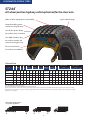
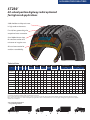
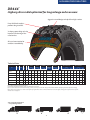
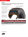
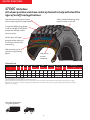
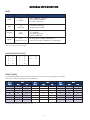
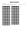
BFGoodrich® Commercial Truck Tire
DATA BOOK
January 2011
To Find Your Nearest BFGoodrich®
Commercial Truck Tire Dealer Call:
United States, 1-877-788-8899
Canada, 1-888-871-6666
Mexico, 011-52-442-296-1600
or visit www.bfgoodrichtrucktires.com
Copyright © 2011 MNA, Inc. All rights reserved. BWT42029 (01/11)
TABLE OF CONTENTS
GENERAL INSTRUCTIONS
Part 1: Safety – Mounting the Tire . . . . . . . . . . . . . . . . . . . . . . . . . . . . . . . 2
Part 2: Mounting and Demounting Tubeless Tires . . . . . . . . . . . . . . . . . 4
Part 3: Mounting and Demounting Tube-Type Tires . . . . . . . . . . . . . . . 7
HIGHWAY/REGIONAL TIRES
ST244™ . . . . . . . . . . . . . . . . . . . . . . . . . . . . . . . . . . . . . . . . . . . . . . . . . . . . . 10
ST230™ . . . . . . . . . . . . . . . . . . . . . . . . . . . . . . . . . . . . . . . . . . . . . . . . . . . . . 11
TR144™ . . . . . . . . . . . . . . . . . . . . . . . . . . . . . . . . . . . . . . . . . . . . . . . . . . . . . 12
DR444™ . . . . . . . . . . . . . . . . . . . . . . . . . . . . . . . . . . . . . . . . . . . . . . . . . . . . 13
ON/OFF ROAD TIRES
ST576™ . . . . . . . . . . . . . . . . . . . . . . . . . . . . . . . . . . . . . . . . . . . . . . . . . . . . . 14
DR675™ . . . . . . . . . . . . . . . . . . . . . . . . . . . . . . . . . . . . . . . . . . . . . . . . . . . . 15
ST565™ Wide Base . . . . . . . . . . . . . . . . . . . . . . . . . . . . . . . . . . . . . . . . . . . 16
Load/Inflation Table . . . . . . . . . . . . . . . . . . . . . . . . . . . . . . . . . . . . . . . . . 17
General Information . . . . . . . . . . . . . . . . . . . . . . . . . . . . . . . . . . . . . 18-19
1
GENERAL INSTRUCTIONS
PART 1: SAFETY – MOUNTING THE TIRE
IMPORTANT: BE SURE TO READ THIS SAFETY INFORMATION.
Make sure that everyone who services tires or vehicles in
your operation has read and understands these warnings.
SERIOUS INJURY OR DEATH CAN RESULT FROM FAILURE TO
FOLLOW SAFETY WARNINGS. No matter how well any tire is
constructed, punctures, impact damage, improper inflation,
improper maintenance, or service factors may cause tire failure
creating a risk of property damage and serious or fatal injury.
Truck operators should examine their tires frequently for snags,
bulges, excessive treadwear, separations, or cuts. If such
conditions appear, demount the tire and see a truck dealer
immediately.
The US Department of Labor Occupational Safety and
Health Administration (OSHA) provides regulations and
publications for safe operating procedures in the servicing of
wheels. Please refer to OSHA Standard 29 CFR Part 1910.177
(Servicing Multi-Piece and Single Piece Rim Wheels).
Specifically, note that the employer shall provide a program
to train all employees who service wheels in the hazards
involved in servicing those wheels and the safety procedures to
be followed. The employer shall ensure that no employee
services any wheel unless the employee has been trained and
instructed in correct procedures of servicing the type of wheel
being serviced, and shall establish safe operating procedures
for such service.
BFGoodrich® Truck Tires provides the following information
to further assist employers to comply with that initiative.
Tire and wheel servicing can be dangerous and must be done only by trained personnel using proper tools and procedures.
Failure to read and comply with all procedures may result in serious injury or death to you or others.
Re-inflation of any type of tire and wheel assembly that has been operated in a run-flat or underinflated condition (80% or less
of recommended operating pressure) can result in serious injury or death. The tire may be damaged on the inside and can explode
during inflation. The wheel parts may be worn, damaged, or dislodged and can explosively separate. Refer to RMA Tire Information
Service Bulletin on potential “zipper ruptures” – TISB Volume 33, Number 3 (December 2007).
RMA (Rubber Manufacturers Association) recommends that any tire suspected of having been run underinflated and/or
overloaded must remain in the safety cage, be inflated to 20 psi OVER maximum pressure marked on the sidewall, and then
be inspected. Do not exceed the maximum inflation pressure for the wheel.
Be sure to reduce pressure to regular operating pressure before placing back in service if the tire has been deemed serviceable.
Use of starting fluid, ether, gasoline, or any other flammable material to lubricate, seal, or seat the beads of a tubeless tire can
cause the tire to explode or can cause the explosive separation of the tire and wheel assembly resulting in serious injury or death.
The use of any flammable material during tire servicing is absolutely prohibited.
Any inflated tire mounted on a wheel contains explosive energy. The use of damaged, mismatched, or improperly assembled tire
and wheel parts can cause the assembly to burst apart with explosive force. If you are struck by an exploding tire, wheel part, or the
blast, you can be seriously injured or killed.
Re-assembly and inflation of mismatched parts can result in serious injury or death. Just because parts fit together does not
mean that they belong together. Check for proper matching of all wheel parts before putting any parts together.
Mismatching tire and wheel component is dangerous. A mismatched tire and wheel assembly may explode and can result in
serious injury or death. This warning applies to any combination of mismatched components and wheel combinations. Never
assemble a tire and wheel unless you have positively identified and correctly matched the parts.
2
ZIPPER RUPTURES
TIRE INSPECTION
A fatigue-related damage, with or without a rupture, occurs in
the sidewall flex area of steel radial light and medium truck tires
when it is subjected to excessive flexing or heat. This zipper rupture
is a spontaneous burst of compressed gas, and the resulting rupture
can range in length anywhere from 12 inches to 3 feet
circumferentially around the tire. This is caused by the damage and
weakening of the radial steel cables as a result of run-flat,
underinflation, or overload. Eventually, the pressure becomes too
great for the weakened cables to hold, and the area ruptures with
tremendous force.
The RMA (Rubber Manufacturers Association) states that
permanent tire damage due to underinflation and/or overloading
cannot always be detected. Any tire known or suspected of having
been run at 80% or less of normal operating inflation pressure
and/or overloaded, could possibly have permanent structural
damage (steel cord fatigue).
The RMA has issued a revised Tire Industry Service Bulletin for
procedures to address zipper ruptures in certain commercial vehicle
tires. The purpose of the bulletin is to describe the inspection
procedures for identifying potential sidewall circumferential
ruptures (also known as “zipper ruptures”) on truck/bus tires and
light-truck tires of steel cord radial construction. Zipper ruptures
can be extremely hazardous to tire repair technicians. Careful
adherence to proper repair procedures is crucial.
For more information contact RMA at [email protected]
or visit www.rma.org.
Tire inspection should always include a thorough inspection of
both sidewalls and inner liner, as this may reveal any potential
damage condition that would cause the tire to become scrap.
Examine the inner liner for creases, wrinkling, discoloration, or
insufficient repairs, and examine the exterior for signs of bumps or
undulations, as well as broken cords, any of which could be
potential out of service causes. Proper OSHA regulations must be
followed when putting any tire and wheel back in service. After
the tire has been inflated to 20 psi in a safety cage, it should
undergo another sidewall inspection for distortions, undulations,
or popping noises indicating a breaking of the steel cords. If this is
the case, immediately fully deflate and scrap the tire. If no
damage is detected, continue to inflate to the maximum pressure
marked on the sidewall. Do not exceed the maximum inflation
pressure for the wheel. Any tire suspected of having been run
underinflated and/or overloaded must remain in the safety cage,
be inflated to 20 psi OVER maximum pressure marked on the
sidewall, and then be inspected.
3
PART 2: MOUNTING AND DEMOUNTING TUBELESS TIRES
In order for a tire to perform properly, it must be mounted on
the correct size wheel. The following are general instructions for
mounting and demounting BFGoodrich® Truck tubeless tires.
Specifics for 19.5" wheels are detailed in the Mounting Tubeless
Tire section (Page 5). For additional detailed instructions on
mounting and demounting truck tires on particular types of
wheels, refer to the instructions of the wheel manufacturer or the
RMA wall charts.
components during the sudden release of the contained gas
of a single piece wheel. Refer to current OSHA standards for
compliance. Do not bolt safety cages to the floor nor add any
other restraints or accessories. Cage should be placed 3 feet
from anything, including the wall. Never stand over a tire or in
front of a tire when inflating. Always use a clip-on valve chuck
with an in-line valve fitted with a pressure gauge or use a
presettable regulator. Additionally, ensure there is a sufficient
length of hose between the clip-on chuck and the in-line
valve (if one is used) to allow the service technician to stand
outside the trajectory zone when inflating.
Trajectory zone means any potential path or route that a wheel
component may travel during an explosive separation or the
sudden release of the pressurized gas, or an area at which the
blast from a single piece wheel may be released.
The trajectory may deviate from paths that are perpendicular
to the assembled position of the wheel at the time of
separation or explosion. See Rubber Manufacturers Association
Tire Information Service Bulletin Volume 33, Number 3
(December 2007) for more information.
TUBELESS TIRE MOUNTING/DEMOUNTING
USING A MOUNTING MACHINE
There are several tire changing machines available for the mount
and demount procedure. Consult the manufacturer’s user manual
for the machine you are using as each operates differently. Full
lubrication of the wheel and beads is still required. Inflation
process requirements remain the same.
DIRECTIONAL TIRES
Truck tires featuring directional tread designs have arrows
molded into the shoulder/edge of the outer ribs to indicate the
intended direction of tire rotation. It is important, to maximize tire
performance, that directional tires be mounted correctly on wheels
to ensure that the directionality is respected when mounted on the
vehicle.
For example, when mounting directional drive tires on a set of
8 wheels, use the drop centers as a reference. Four tires should be
mounted with the arrows pointing to the left of the technician and
four tires with the arrows pointing to the right. This ensures that
when the assemblies are fitted onto the vehicle that all tires can be
pointed in the desired direction of rotation.
Directional steer tires should be mounted in a similar fashion,
one each direction, to ensure both are pointed forward.
Once directional tires are worn greater than 50%, there is
generally no negative effect of running them in a direction opposite
to the indicated direction of rotation.
Operating directional tires from new to 50% worn in the
opposite direction of that indicated on the tire will result in the
premature onset of irregular wear, excessive noise levels, and
significantly reduced tread life.
2. TIRE AND WHEEL LUBRICATION
It is essential that an approved tire mounting lubricant be used.
Preferred materials for use as bead lubricants are vegetable based
and mixed with proper water ratios per manufacturer’s instructions.
Never use antifreeze, silicones, or petroleum-base lubricants as this
will damage the rubber. Lubricants not mixed to the manufacturer’s
specifications may have a harmful effect on the tire and wheel.
The lubricant serves the following three purposes:
• Helps minimize the possibility of damage to the tire beads from
the mounting tools.
• Helps ease the insertion of the tire onto the wheel by lubricating
all contacting surfaces.
• Assists proper bead seating (tire and wheel centering) and helps
to prevent eccentric mountings.
Apply a clean lubricant to all portions of the tire bead area and
the exposed portion of the flap using sufficient but sparing
quantities of lubricant. Also, lubricate the entire rim surface of
the wheel. Avoid using excessive amounts of lubricant, which can
become trapped between the tire and tube and can result in tube
damage and rapid air loss.
1. SELECTION OF PROPER COMPONENTS AND
MATERIALS
a. All tires must be mounted on the proper wheel as indicated in
the specification tables. For complete tire specifications, refer to
application specific data books.
b. Make certain that wheel is proper for the tire dimension.
c. Always install new valve cores and metal valve caps
containing plastic or rubber seals.
d. Always replace the rubber valve stem on a 16" through 19.5"
wheel.
e. Always use a safety device such as an inflation cage
or other restraining device that will constrain all wheel
CAUTION: It is important that tire lubricant be clean and free
of dirt, sand, metal shavings, or other hard particles. The following
practice is recommended:
a. Use a fresh supply of tire lubricant each day, drawing from
a clean supply source and placing the lubricant in a clean
portable container.
b. Provide a cover for the portable container and/or other means
to prevent contamination of the lubricant when not in use.
For lubricants in solution, we suggest the following method
4
that has proven to be successful in helping to minimize
contamination and prevent excess lubricant from entering the
tire casing: provide a special cover for the portable container
that has a funnel-like device attached. The small opening of the
funnel should be sized so that when a swab is inserted through
the opening into the reserve of lubricant and then withdrawn,
the swab is compressed, removing excess lubricant. This allows
the cover to be left in place providing added protection. A mesh
false bottom in the container is a further protection against
contaminants. The tire should be mounted and inflated
promptly before lubricant dries.
symmetric wheel profile facilitating tire mounting from either
side.) It is imperative that the tire always be mounted and
dismounted only from the short side. Failure to do this will likely
result in damaged tire beads that could eventually cause rapid
gas loss due to casing rupture. This is particularly important on
19.5 inch RW (reduced well) aluminum wheels which, contrary to
the norm, have their drop center located close to the disc side.
Do not use 19.5 x 7.50 wheel for the 305/70R19.5 tire size.
All 19.5 inch tubeless wheels should be mounted from the short
side. Care should be taken to ensure that any internal
monitoring system molded in the tire or on the wheel is not
damaged or dislodged during this service.
5. Do not use any kind of hammer. Severe inner liner damage
may occur resulting in sidewall separation and tire destruction.
Use only proper mounting levers;
3. PREPARATION OF WHEELS AND TIRES
a. Always wear safety goggles or face shields when buffing or
grinding wheels.
b. Inspect wheel assemblies for cracks, distortion, and
deformation of flanges. Using a file and/or emery cloth, smooth
all burrs, welds, dents, etc. that are present on the tire side of
the wheel. Inspect the condition of bolt holes on the wheels.
Rim flange gauges and ball tapes are available for measuring
wear and circumference of aluminum wheels.
c. Remove rust with a wire brush and apply a rust inhibiting paint
on steel wheels. The maximum paint thickness is 0.0035" on
the disc face of the wheel.
d. Remove any accumulation of rubber or grease that might be
stuck to the tire, being careful not to damage it. Wipe the beads
down with a dry rag.
DO NOT USE A DUCK BILL HAMMER.
Re-inflation of any type of tire and wheel assembly
that has been operated in a run-flat or underinflated
condition (less than 80% of normal recommended
operating pressure) can result in serious injury or
death. The tire may be damaged on the inside and can
explode during inflation. The wheel parts may be
worn, damaged or dislodged and can explosively
separate.
MOUNTING TUBELESS
1. Inspect the condition of the bolt holes on the wheels, and look
for signs of fatigue. Check flanges for excessive wear by using
the wheel manufacturer’s flange wear indicator.
2. Replace valve core, and inspect valve stem for damage and
wear. Michelin recommends always replacing the valve stem
and using a new valve stem grommet. Ensure valve stem is
installed using the proper torque value. 80-125 in/lbs
(7-11 ft/lbs) for standard aluminum wheels and 35-55 in/lbs
(3-5 ft/lbs) for standard tubeless steel wheels. Ensure the valve
core is installed using the proper torque value of 1.5-4 in/lbs.
To prevent galvanic corrosion on aluminum wheels, lubricate
the threads and O-ring of the valve stem with a
non-waterbased lubricant before installation.
3. Apply the tire and wheel lubricant to the rim surface of the wheel
and bead area of the tire. When applying lubricant to the wheel,
lubricate the entire rim surface from flange to flange. The tire
should be mounted and inflated before the lubricant dries.
4. With short ledge up, lay the tire over the wheel opposite the
valve side and work it on with proper tubeless tire tools, making
full use of the drop center well. Drop center wheels are typically
designed with an off-set drop center to accommodate wheel
width and brake clearance. This creates a “short side” and a “long
side” on the wheel. (Some drop center wheels are designed with a
INFLATION OF TUBELESS TIRES
1. Lay tire/wheel assembly horizontally and inflate to no more
than 5 psi to position the beads on the flanges. OSHA dictates
no more than 5 psi outside the cage to seat the beads.
2. To complete the seating of the beads, place the assembly in an
OSHA (Occupational Safety and Health Administration)
compliant inflation restraining device (i.e. safety cage) and
inflate to 20 psi. Check the assembly carefully for any signs of
distortion or irregularities from run-flat. If run-flat is detected,
scrap the tire.
3. If no damage is detected, continue to inflate to the maximum
pressure marked on the sidewall. RMA (Rubber Manufacturers
Association) recommends that if any tire suspected of having
been underinflated and/or overloaded must remain in the
safety cage at 20 psi over the maximum pressure marked on the
sidewall. Do not exceed the maximum inflation pressure for the
wheel. RMA requires that all steer sidewall tires are inflated
without a valve core.
4. Ensure that the guide rib (GG Ring/mold line) is positioned
concentrically to the rim flange with no greater than 2⁄ 32" of
difference found circumferentially. Check for this variation by
5
measuring at four sidewall locations (12, 3, 6, 9 o’clock).
If bead(s) did not seat, deflate tire, re-lubricate the bead seats
and re-inflate.
Note: As a general guide in vibration analysis, the 30/60/90
rule may apply:
.030-.060 (1⁄ 32 to 2 ⁄ 32 inch) = No action is required. Limited
possibility for vibration exists, and this range maximizes the
ability to balance properly.
.061-.090 (2 ⁄ 32 to 3⁄ 32 inch) = Corrective action would be to
perform the 3 R’s, after deflating the tire.
– Rotate the tire on the wheel
– Re-lubricate the tire and wheel (ensure the wheel is very
clean)
– Re-inflate ensuring your initial inflation is with the tire lying
horizontal (3-5 psi max)
>.090 (>3⁄ 32 inch) = Perform 3 R’s if mismount is indicated;
however, when the reading is this high, it usually requires
checking runout on these component parts:
wheels/hubs/drums/wheel bearings.
5. After beads are properly seated, place the tire in safety cage
and inflate assembly to maximum pressure rating shown on the
sidewall, then reduce to operating pressure. Check valve core for
leakage, then install suitable valve cap. Consider the use of
inflate-thru or double seal valve caps for easier pressure
maintenance.
DEMOUNTING OF TUBELESS TIRES
1. If still fitted on the vehicle, completely deflate the tire by
removing the valve core. In the case of a dual assembly,
completely deflate both tires before removing them from the
vehicle (OSHA requirement). Run a wire or a pipe cleaner
through the valve stem to ensure complete deflation.
2. With the tire assembly lying flat (after deflating the tire), break
the bead seat of both beads with a bead breaking tool. Do not
use hammers of any type to seat the bead. Striking a wheel
assembly with a hammer of any type can damage the tire or
wheel and endanger the installer. Use a steel duck bill hammer
only as a wedge. Do not strike the head of a hammer with
another hard faced hammer – use a rubber mallet.
3. Apply the vegetable-based lubricant to all surfaces of the bead
area of the tire.
4. Beginning at the valve, remove the tire from the wheel. Starting
at the valve will minimize chances of damaging the valve
assembly. Make certain that the rim flange with the tapered
ledge that is closest to the drop center is facing up. Insert the
curved ends of the tire irons between the tire and rim flange.
Step forward into the drop center and drop the bars down,
lifting the tire bead over the rim flange. Hold one tire iron in
position with your foot. Pull the second tire iron out and
reposition it about 90 degrees from the first iron. Pull the
second tire iron towards the center of the wheel. Continue to
work tools around wheel until first bead is off the wheel.
5. Lift the assembly, place and rotate the tire iron to lock on the
back rim flange, allow the tire to drop, and with a rocking
motion remove the tire from the wheel.
6
PART 3: MOUNTING AND DEMOUNTING TUBE-TYPE TIRES
A tire cannot perform properly unless it is mounted properly on the correct size wheel. The following are general instructions for
demounting and mounting BFGoodrich® tube-type tires. For detailed instructions on mounting and demounting truck tires on particular types
of wheels, refer to the instructions of the wheel manufacturer or the RMA wall charts.
Do not re-inflate any tires that have been run underinflated or flat without careful inspection for damage. If run-flat
damage is detected, scrap the tire. A tire is considered run-flat if it is found to be less than 80% of normal
recommended operating pressure. This can result in serious injury or death. The tire may be damaged on the inside and
can explode during inflation. The wheel parts may be worn, damaged or dislodged and can explosively separate.
may deviate from paths that are perpendicular to the assembled
position of the wheel at the time of separation or explosion.
1. SELECTION OF PROPER COMPONENTS AND
MATERIALS
NEVER WELD OR APPLY HEAT TO A WHEEL ON WHICH
A TIRE IS MOUNTED.
a. All tires must be mounted with the proper tube and flap
(if required) and wheel as indicated in the specification tables.
For complete tire specifications, refer to application specific
data books.
b. Make certain that wheel components are properly matched
and of the correct dimensions for the tire.
c. Always fit a new tube in a new mounting. Since a tube will
exhibit growth in size through normal use, an old tube used in
a new mounting increases the possibility of tube creasing and
chafing, possibly resulting in failure.
d. Always install a new flap in a new mounting. A flap, through
extended use, becomes hard and brittle. After a limited time,
it will develop a set to match the tire and wheel in which it is
fitted. Therefore, it will not exactly match a new tire and wheel
combination.
e. Always install new valve cores and metal valve caps
containing plastic or rubber seals. For tires requiring
O-rings, be sure to properly install a new silicone O-ring at
every tire change.
f. Always use a safety device such as an inflation cage or other
restraining device that will constrain all wheel components
during an explosive separation of a multi-piece wheel, or during
the sudden release of the contained gas of a single piece wheel
that is in compliance with OSHA (Occupational Safety and
Health Administration) standards. Do not bolt restraining device
to the floor. Never stand over a tire or in front of a tire when
inflating. Always use a clip-on valve chuck with an in-line valve
with a pressure gauge or a presettable regulator. Additionally,
ensure there is a sufficient length of hose between the clip-on
chuck and the in line valve (if one is used) to allow the service
technician to stand outside the trajectory path when inflating.
Trajectory zone means any potential path or route that a wheel
component may travel during an explosive separation, or the
sudden release of the pressurized gas, or an area at which the
blast from a single piece wheel may be released. The trajectory
2. TIRE AND WHEEL LUBRICATION
It is essential that an approved tire mounting lubricant
be used. Preferred materials for use as bead lubricants are
vegetable based and mixed with proper water ratios per
manufacturer’s instructions. Never use antifreeze, silicones, or
petroleum-base lubricants as this will damage the rubber.
Lubricants not mixed to the manufacturer’s specifications may
have a harmful effect on the tire and wheel.
The lubricant serves the following three purposes:
• Helps minimize the possibility of damage to the tire beads
from the mounting tools.
• Helps ease the insertion of the tire onto the wheel by
lubricating all contacting surfaces.
• Assists proper bead seating (tire and wheel centering) and
helps to prevent eccentric mountings.
Apply a clean lubricant to all portions of the tire bead area and
the exposed portion of the flap using sufficient but sparing
quantities of lubricant. Also, lubricate the entire rim surface.
Avoid using excessive amounts of lubricant, which can become
trapped between the tire and tube and can result in tube
damage and rapid gas loss.
CAUTION: It is important that tire lubricant be clean and free
of dirt, sand, metal shavings, or other hard particles. The following
practice is recommended:
a. Use a fresh supply of tire lubricant each day, drawing from a
clean supply source and placing the lubricant in a clean
portable container.
b. Provide a cover for the portable container and/or other means
to prevent contamination of the lubricant when not in use. For
lubricants in solution, we suggest the following method, which
has proven to be successful in helping to minimize
contamination and prevent excess lubricant from entering the
7
tire casing: provide a special cover for the portable container
that has a funnel-like device attached. The small opening of the
funnel should be sized so that when a swab is inserted through
the opening into the reserve of lubricant and then withdrawn,
the swab is compressed, removing excess lubricant. This allows
the cover to be left in place providing added protection.
A mesh false bottom in the container is a further protection
against contaminants. The tire should be mounted and inflated
promptly before lubricant dries.
DEMOUNTING TUBE-TYPE TIRE
1. Before loosening any nuts securing the tire and wheel assembly
to the vehicle, remove the valve core and deflate completely.
If working on a dual assembly, completely deflate both tires.
Run a wire or pipe cleaner through the valve stem to ensure
complete deflation. This is to prevent a possible accident.
2. Remove the tire and wheel assembly from the vehicle and place
on the floor with the side ring up.
3. Run a wire or pipe cleaner through the valve stem to clear the
valve stem.
4. Apply lubricant to all surfaces of the bead area of the tire. Use
the duck bill hammer, with the rubber mallet as a wedge, or a
slide hammer.
5. For two-piece wheels, remove the side ring by pushing the tire
bead down. Insert the tapered end of the rim tool into the
notch and pry the side ring out of the gutter. Pry progressively
around the tire until the side ring is free of the gutter.
6. For three-piece wheels, remove the lock ring by pushing the
side rings and the tire bead down. Insert the tapered end of the
rim tool into the notch near the split in the lock ring, push the
tool downward, and pry the lock ring outward to remove the
gutter from the base. Use the hooked end of the rim tool
progressively around the tire to complete the removal, then lift
off the side ring.
7. Turn the assembly over.
8. Unseat the remaining tire bead from the rim, and lift the rim
from the tire.
3. PREPARATION OF WHEELS AND TIRES
a. Always wear safety goggles or face shields when buffing or
grinding wheels.
b. Inspect wheel assemblies for cracks, distortion, and
deformation of flanges. Using a file and/or emery cloth,
smooth all burrs, welds, dents, etc. that are present on the tire
side of the wheel. Inspect the condition of bolt holes on the
wheels. Rim flange gauges and ball tapes are available for
measuring wear and circumference of aluminum wheels.
c. Remove rust with a wire brush and apply a rust inhibiting paint
on steel wheels. The maximum paint thickness is .0035" on the
disc face of the wheel.
d. Remove any accumulation of rubber or grease stuck to the tire,
being careful not to damage it. Wipe the beads down with a
dry rag.
Any inflated tire mounted on a wheel contains
explosive energy. The use of damaged, mismatched
or improperly assembled tire and wheel parts can
cause the assembly to burst apart with explosive
force. If you are struck by an exploding tire, wheel
part or the blast, you can be seriously injured or
killed. Do not attempt to dismount the tire while the
assembly is still installed on the vehicle. Use proper
tools to demount or mount wheel parts. Never use a
steel hammer to seat wheel parts – use only rubber,
plastic, or brass-tipped mallets. Striking a wheel
assembly with a hammer of any type can damage the
tire or wheel and endanger the installer. Use a steel
duck bill hammer only as a wedge. Do not strike the
head of a hammer with another hard-faced
hammer – use a rubber mallet.
Re-assembly and inflation of mismatched parts can
result in serious injury or death. Just because parts
fit together does not mean that they belong
together. Check for proper matching of all wheel
parts before putting any parts together. Inspect the
tire and the wheel for any damage that would
require them to be placed out of service.
Mismatching tire and wheel components is
dangerous. A mismatched tire and wheel assembly
may explode and can result in serious injury or
death. This warning applies to any combination of
mismatched components, and wheel combinations.
Never assemble a tire and wheel unless you have
positively identified and correctly matched the
parts.
8
6. Apply a proper tire lubricant to the inside and outside
surfaces of both beads and to that portion of the flap that
appears between the beads. Make sure that excess lubricant
does not run down into the tire.
7. Follow Steps 4 through 8 of the “Mounting of Tube-Type Tires.”
MOUNTING TUBE-TYPE TIRE
1. Insert the proper size tube into the tire and partially inflate
(3 psi) to round out the tube (with larger sizes it may be
necessary to use bead spreaders – see below for mounting
instructions).
2. Insert the valve through the flap valve hole. (Make sure the
reinforced patch that is directly over the flap valve hole is facing
outwards.) Then insert the remainder of the flap into the tire.
3. Check the flap wings to ensure against folding. This is easily
accomplished by placing your hand into one tire side, then the
other, and then running your hand along the entire flap wing.
4. Inflate the tube until the flap is secured against the tire wall
and the beads start to spread apart, making sure not to exceed
3 psi.
5. Apply a proper tire lubricant to both beads, exposed flap, and
fully to the rim. Make sure that excess lubricant does not run
down into the tire.
6. Lay the wheel flat on the floor with the gutter side up. Place
tire, tube, and flap on the wheel, taking care to center the valve
in the slot.
7. For two-piece wheels, place the side ring on the rim base so
that the ring split is opposite the valve stem by placing the
leading end (end without the notch) of the ring into the groove
in the wheel, and progressively walk the side ring into place.
Ensure the ring is fully seated in the gutter.
8. For three-piece wheel, place the side ring on the rim base and
stand on the ring to position it below the gutter rim base. Snap
the leading end (end without the notch) of the lock ring into
the gutter of the rim base, and progressively walk the lock ring
into place. Ensure the ring is fully seated in the gutter.
INFLATION OF TUBE-TYPE TIRES
1. An inflation line with an extension (30" minimum), in-line
gauge, and a clip-on valve chuck should be used for inflation.
Remove valve core and lay the assembly flat on the ground.
Using an approved restraining device, inflate partially to seat
beads to no more than 3 psi. While the tire is still in the
restraining device, make sure all wheel components are
centered and locked properly. If not, the tire must be deflated,
broken down, relubricated and reinflated. Do not attempt to
seat the lock ring by means of a hammer.
2. Deflate the tire by removing the inflation line. This is to allow
the tube to relax, thus, eliminating any wrinkles or uneven
stretching that may have occurred during primary inflation.
3. With the valve core still removed, place the dual and wheel
assembly into an approved safety cage or other approved
restraining device meeting OSHA (Occupational Safety and
Health Administration) standards, and reinflate the tire to the
pressure shown on the sidewall in order to ensure proper bead
seating. Then adjust the tire to the proper operating pressure.
Never stand over a tire or in front of a tire when inflating.
Always use a clip-on valve chuck with an in-line valve with
a pressure gauge or a presettable regulator and a sufficient
length of hose between the clip-on chuck and in-line valve
(if one is used) to allow the employee to stand outside the
trajectory path when inflating. RMA (Rubber Manufacturers
Association) requires that all steel sidewall radial tires are
inflated without a valve core.
4. Reinspect the assembly for proper positioning and seating of
all components.
5. Check for leaks, and install a suitable valve cap.
MOUNTING OF TUBE-TYPE TIRES USING
MANUAL SPREADERS
1. Follow Steps 1 through 3 of the “Mounting of Tube-Type Tires.”
However, before inserting the flap into the tire, position two
bead spreaders in the following manner:
a. Place the first at a 90° angle to the valve.
(Flap is positioned between the spreader and the tube.)
b. Place the second directly opposite the first.
c. Spread the beads and insert the flap.
d. Close the beads, remove spreaders.
2. Follow Steps 4 through 8 of the “Mounting of Tube-Type Tires.”
Do not re-inflate any tires that have been run
underinflated or flat without careful inspection
for damage.
If run-flat damage is detected, scrap the tire.
A tire is considered run-flat if it is found to be
less than 80% of normal recommended operating
pressure.
MOUNTING OF TUBE-TYPE TIRES USING
AUTOMATIC SPREADERS
1.
2.
3.
4.
Spread the tire beads.
Inflate the tube to approximately 3 psi.
Insert the tube into the tire.
Insert the valve through the flap valve hole.
(As mentioned, the flap reinforced valve area must face
outwards.) Insert the remainder of the flap into the tire.
5. Close the beads.
9
HIGHWAY/REGIONAL TIRES
ST244
™
All-wheel position highway radial optimized for the steer axle.
Wider tread for improved wear and handling.
Stylish sidewall design.
Unique decoupling groove
to help resist irregular wear.
Five-rib, four-groove design
for excellent water evacuation.
••
••
••
••
•
•
• • • • • • • • • • • • • • •••
•
•
•
•
•
•
•• • • • • • • • • • • • • • • • • • •
• • • •• • • • •
•• •••
• • •• • • • •• •
Over 1900 miniature sipes
for excellent traction and
resistance to irregular wear.
•
••
••
••
•
••
••
••
•••
• • • • • • • • • • • • • • • • • • • • • • • • • • • • • ••
•
•
•
•
•
•
•
• • ••
All-steel construction
for excellent retreadability.
••
••
••
••
••
••
••
•
••
••
••
•••
••
••
••
••
Technical Data
Size
Tread Max.
Load Catalog Depth Speed
Range Number
(1)
32nds mph
Loaded
Radius
Overall
Diameter
Approved
Wheels
Overall Width
(2)
Min. Dual
Spacing (2)
Revs
per
Mile
Max. Load Per Tire
Single
Max. Load Per Tire
Dual
in.
mm.
in.
mm.
(Measuring wheel
listed first.)
in.
mm
lbs.
psi
kg.
kPa
lbs.
psi
kg.
kPa
11R22.5
G
40525
18
75
19.1
486
41.1
1043 10.5
267
8.25, 7.50
12.5
318
505
6175
105
2800
720
5840
105
2650
720
11R22.5
H
92401
18
75
19.2
487
41.1
1044 12.2
309
8.25, 7.50
12.5
318
505
6610
120
3000 830 6005
120
2725
830
275/80R22.5
G
61456
18
75
18.6
472
40.0 1016
10.9
277
8.25, 7.50
12.2
311
519
6175
110
2800
2575
760
720
mm.
in.
760
5675
110
11R24.5
G
51477
18
75
20.2
513
43.3 1100
11.0
279
8.25, 7.50
12.5
318
478
6610
105
3000
720
6005
105
2725
11R24.5
H
58109
18
75
20.2
513
43.3 1100
11.0
279
8.25, 7.50
12.5
318
478
7160
120
3250
830
6610
120
3000 830
275/80R24.5
G
77897
18
75
19.2
488
41.3 1049 10.6
269
8.25, 7.50
12.2
311
502
6175
110
2800
760
5675
110
2575
Note: Wheel listed first is the measuring wheel.
(1) Exceeding the lawful speed limit is neither recommended nor endorsed.
(2) Tire section widths and overall widths will change 0.1 inch (2.5 mm) for each 1/4 inch change in wheel width. Minimum dual spacing should be adjusted accordingly.
BFGoodrich® tires are subject to a continuous development program. BFGoodrich® Commercial Truck Tires reserves the right to change product specifications at any time
without notice or obligation.
Recommended Application
Acceptable Application
10
760
HIGHWAY/REGIONAL TIRES
ST230
™
All-wheel position highway radial optimized
for high scrub applications.
Solid shoulders to help resist wear
in high scrub environments.
Five-rib, four-groove design for
exceptional water evacuation.
Over 1900 miniature sipes
for excellent traction and
resistance to irregular wear.
All-steel construction for
excellent retreadability.
Technical Data
Size
Tread Max.
Load Catalog Depth Speed
Range Number
(1)
32nds mph
Loaded
Radius
Overall
Diameter
Overall Width
(2)
Approved
Wheels
Min. Dual
Spacing (2)
Revs
per
Mile
Max. Load Per Tire
Single
Max. Load Per Tire
Dual
in.
mm.
in.
mm.
in.
mm.
(Measuring wheel
listed first.)
in.
mm
lbs.
psi
kg.
kPa
lbs.
psi
kg.
kPa
225/70R19.5
G
74208
15
75
14.8
376
32.1
815
9.2
233
6.00, 6.75
10.0
254
647
3970
110
1800
760
3750
110
1700
760
245/70R19.5
G
89688
16
75
15.6
396
33.5
852
9.7
246
6.75, 7.50
10.9
277
624
4540
110
2060
760
4300
110
1950
760
10R22.5
G
62086
17
75
18.6
472
39.8
1012
10.0
255
7.50, 6.75, 8.25
11.4
288
521
5675
115
2575
790
5355
115
2430
790
11R22.5
H
68045
18
75
19.1
486
41.1
1043
11.1
282
8.25, 7.50
12.5
318
505
6610
120
3000
830
6005
120
2725
830
12R22.5
H
63223
19
75
19.8
503
42.4 1077
11.3
286
8.25, 9.00
13.2
335
487
7390
120
3350
830
6780
120
3075
830
255/70R22.5
H
95971
17
75
17.1
435
36.6
929
10.2
258
8.25, 7.50
11.6
295
566
5510
120
2500
830
5070
120
2300
830
275/80R22.5
G
50614
18
75
18.6
472
40.0 1016
10.9
277
8.25, 7.50
12.2
311
518
6175
110
2800
760
5675
110
2575
760
315/80R22.5
L
55458
17
75
19.6
499
42.4 1076
12.5
317
9.00
13.8
351
489
9090
130
4125
900
8270
130
3750
900
11R24.5
H
79184
18
75
20.2
513
43.3 1100
11.0
279
8.25, 7.50
12.5
318
478
7160
120
3250
830
6610
120
3000
830
275/80R24.5
G
71892
18
75
19.2
488
41.3 1049 10.6
269
8.25, 7.50
12.2
311
503
6175
110
2800
760
5675
110
2575
760
Note: Wheel listed first is the measuring wheel.
(1) Exceeding the lawful speed limit is neither recommended nor endorsed.
(2) Tire section widths and overall widths will change 0.1 inch (2.5 mm) for each 1/4 inch change in wheel width. Minimum dual spacing should be adjusted accordingly.
BFGoodrich® tires are subject to a continuous development program. BFGoodrich® Commercial Truck Tires reserves the right to change product specifications at any time
without notice or obligation.
Recommended Application
Acceptable Application
11
HIGHWAY/REGIONAL TIRES
TR144
™
Highway radial optimized for the free rolling axles.
Shoulder groove designed to help
improve resistance to irregular wear.
Stylish sidewall design.
Optimized five-rib design to help resist
irregular wear on free rolling axles.
See-through grooves designed
to improve wet traction.
All-steel construction for
excellent retreadability.
Technical Data
Size
Tread Max.
Load Catalog Depth Speed
Range Number
(1)
32nds mph
Loaded
Radius
Overall
Diameter
Approved
Wheels
Overall Width
(2)
Min. Dual
Spacing (2)
Revs
per
Mile
Max. Load Per Tire
Single
Max. Load Per Tire
Dual
in.
mm.
in.
mm.
(Measuring wheel
listed first.)
in.
mm
lbs.
psi
kg.
kPa
lbs.
psi
kg.
kPa
11R22.5
G
02041
12
75
19.0
484
40.8 1036
11.2
285
8.25, 7.50
12.5
318
508
6175
105
2800
720
5840
105
2650
720
275/80R22.5
G
39833
12
75
18.4
468
39.7 1008
11.1
281
8.25, 7.50
12.2
311
523
6175
110
2800
760
5675
110
2575
760
11R24.5
G
06457
12
75
20.0
508
43.0 1092
11.1
283
8.25, 7.50
12.5
318
482
6610
105
3000
720
6005
105
2725
720
275/80R24.5
G
27373
12
75
19.1
485
40.8 1036 10.8
274
8.25, 7.50
12.2
311
507
6175
110
2800
760
5675
110
2575
760
in.
mm.
Note: Wheel listed first is the measuring wheel.
(1) Exceeding the lawful speed limit is neither recommended nor endorsed.
(2) Tire section widths and overall widths will change 0.1 inch (2.5 mm) for each 1/4 inch change in wheel width. Minimum dual spacing should be adjusted accordingly.
BFGoodrich® tires are subject to a continuous development program. BFGoodrich® Commercial Truck Tires reserves the right to change product specifications at any time
without notice or obligation.
Recommended Application
Acceptable Application
12
HIGHWAY/REGIONAL TIRES
DR444
™
Highway drive radial optimized for long mileage and even wear.
Aggressive tread design to help deliver high traction.
Deep 28/32nds tread to
promote long tread life.
V-shape groove design to help
improve self-cleaning of the
tread surface.
All-steel construction for
excellent retreadability.
Technical Data
Size
Tread Max.
Load Catalog Depth Speed
Range Number
(1)
32nds mph
Loaded
Radius
Overall
Diameter
Approved
Wheels
Overall Width
(2)
Min. Dual
Spacing (2)
Revs
per
Mile
Max. Load Per Tire
Single
Max. Load Per Tire
Dual
in.
mm.
in.
mm.
(Measuring wheel
listed first.)
in.
mm
lbs.
psi
kg.
kPa
lbs.
psi
kg.
kPa
11R22.5
G
77081
28
75
19.4
493
41.8 1062
11.2
284
8.25, 7.50
12.5
318
497
6175
105
2800
720
5840
105
2650
720
11R22.5
H
98035
28
75
19.4
493
41.8 1062
11.2
284
8.25, 7.50
12.5
318
497
6610
120
3000 830 6005
120
2725
830
275/80R22.5
G
90375
28
75
18.9
480
40.6 1032 10.9
277
8.25, 7.50
12.2
311
511
6175
110
2800
2575
760
720
in.
mm.
760
5675
110
11R24.5
G
52321
28
75
20.5
521
43.9
1116
11.0
279
8.25, 7.50
12.5
318
472
6610
105
3000
720
6005
105
2725
11R24.5
H
89861
28
75
20.5
521
43.9
1116
11.0
279
8.25, 7.50
12.5
318
472
7160
120
3250
830
6610
120
3000 830
275/80R24.5
G
55617
28
75
19.5
495
41.9 1064 10.6
269
8.25, 7.50
12.2
311
500
6175
110
2800
760
5675
110
2575
760
Note: Wheel listed first is the measuring wheel.
(1) Exceeding the lawful speed limit is neither recommended nor endorsed.
(2) Tire section widths and overall widths will change 0.1 inch (2.5 mm) for each 1/4 inch change in wheel width. Minimum dual spacing should be adjusted accordingly.
BFGoodrich® tires are subject to a continuous development program. BFGoodrich® Commercial Truck Tires reserves the right to change product specifications at any time
without notice or obligation.
Recommended Application
Acceptable Application
13
ON/OFF ROAD TIRES
ST576
™
All-wheel position radial optimized to help withstand the rigor
of on/off road applications.
Exceptional sidewall protection helps
improve resistance to impacts.
Aggressive shoulder design with offset
blocks for exceptional traction.
Deep 21/32nds tread depth
for long original tread life.
Specially formulated compound
for optimized tread life and
resistance to the abrasion
and cutting associated with
on/off road use.
Robust 4-belt construction
for excellent protection
against road hazards and
dependable retreadability.
Technical Data
Size
Tread Max.
Load Catalog Depth Speed
Range Number
(1)
32nds mph
Loaded
Radius
Overall
Diameter
Approved
Wheels
Overall Width
(2)
Min. Dual
Spacing (2)
Revs
per
Mile
Max. Load Per Tire
Single
Max. Load Per Tire
Dual
in.
mm.
in.
mm.
(Measuring wheel
listed first.)
in.
mm
lbs.
psi
psi
kg.
kPa
11R22.5
H
50677
21
65
19.3
489
41.2 1047
11.2
284
8.25, 7.50
12.5
318
502
6610
120
3000 830 6005
120
2725
830
11R24.5
H
86409
21
65
20.2
512
43.2 1098
11.2
284
8.25, 7.50
12.5
318
479
7160
120
3250
120
3000 830
in.
mm.
kg.
kPa
830
lbs.
6610
Note: Wheel listed first is the measuring wheel.
(1) Exceeding the lawful speed limit is neither recommended nor endorsed.
(2) Tire section widths and overall widths will change 0.1 inch (2.5 mm) for each 1/4 inch change in wheel width. Minimum dual spacing should be adjusted accordingly.
BFGoodrich® tires are subject to a continuous development program. BFGoodrich® Commercial Truck Tires reserves the right to change product specifications at any time
without notice or obligation.
Recommended Application
Acceptable Application
14
ON/OFF ROAD TIRES
DR675
™
Drive radial optimized to help provide excellent traction
in on/off road applications.
Aggressive shoulder design with offset
blocks for exceptional traction.
Exceptional sidewall protection for
excellent resistance to impacts.
Deep 30/32nds tread
for long tread life.
Tread compound tailored
for rigor of on/off road
applications.
Robust 4-belt construction
for excellent protection
against road hazards and
dependable retreadability.
Technical Data
Size
Tread Max.
Load Catalog Depth Speed
Range Number
(1)
32nds mph
Loaded
Radius
Overall
Diameter
Approved
Wheels
Overall Width
(2)
Min. Dual
Spacing (2)
Revs
per
Mile
Max. Load Per Tire
Single
Max. Load Per Tire
Dual
in.
mm.
in.
mm.
(Measuring wheel
listed first.)
in.
mm
lbs.
psi
psi
kg.
kPa
11R22.5
H
47237
30
65
19.6
498
41.9 1064
11.2
284
8.25, 7.50
12.5
318
494
6610
120
3000 830 6005
120
2725
830
11R24.5
H
80401
30
65
20.5
521
44.0 1118
11.3
287
8.25, 7.50
12.5
318
471
7160
120
3250
120
3000 830
in.
mm.
kg.
kPa
830
lbs.
6610
Note: Wheel listed first is the measuring wheel.
(1) Exceeding the lawful speed limit is neither recommended nor endorsed.
(2) Tire section widths and overall widths will change 0.1 inch (2.5 mm) for each 1/4 inch change in wheel width. Minimum dual spacing should be adjusted accordingly.
BFGoodrich® tires are subject to a continuous development program. BFGoodrich® Commercial Truck Tires reserves the right to change product specifications at any time
without notice or obligation.
Recommended Application
Acceptable Application
15
ON/OFF ROAD TIRES
ST565
™
Wide Base
All-wheel-position wide base radial optimized to help withstand the
rigor of on/off road applications.
Deep circumferential grooves channel
water to help improve wet road traction.
Offset shoulder block design helps
improve traction in soft soil.
Size specific bridging (high bridges
in 385, low bridges in 445) define
smooth ride and high traction
where necessary.
Variable pitch wall angles
designed to help reduce the
risk of stone retention and
stone drilling.
Wide-protector ply for
resistance to penetrating
objects.
Chip and cut
resistant
compound.
Technical Data
32nds
Max.
Speed
(1)
mph
in.
mm.
in.
mm.
in.
19
65
19.5
496
42.2
1071
14.9
49039
19
65
20.4
518
44.4
1128
42131
20
65
20.9
530
45.5
1156
Size
Load
Range
Catalog
Number
385/65R22.5
J
64873
425/65R22.5
L
445/65R22.5
L
Tread
Depth
Loaded
Radius
Overall
Diameter
Overall Width
(2)
Approved
Wheels
Max. Load Per Tire
Single
mm.
(Measuring wheel
listed first.)
Revs
per
Mile
lbs.
psi
kg.
kPa
378
11.75, 12.25
493
9370
120
4250
830
16.5
420
13.00, 12.25
470
11400
120
5150
830
17.7
450
14.00, 13.00
458
12300
120
5600
830
Note: Wheel listed first is the measuring wheel.
(1) Exceeding the lawful speed limit is neither recommended nor endorsed.
(2) Tire section widths and overall widths will change 0.1 inch (2.5 mm) for each 1/4 inch change in wheel width. Minimum dual spacing should be adjusted accordingly.
BFGoodrich® tires are subject to a continuous development program. BFGoodrich® Commercial Truck Tires reserves the right to change product specifications at any time
without notice or obligation.
Recommended Application
Acceptable Application
16
MAXIMUM LOADS PER AXLE AT COLD INFLATION PRESSURES
PSI
65
70
75
80
85
90
95
100
105
110
115
120
125
130
kPa
450
480
520
550
590
620
660
690
720
760
790
830
860
900
7940 (G)
18180 (L)
SINGLE
5510
5790
6080
6390
6630
6900
7280
7430
7690
DUAL
10400
10880
11440
12000
12460
12980
13660
13960
14460
15000 (G)
SINGLE
2500
2620
2760
2900
3000
3140
3300
3380
3480
3600 (G)
DUAL
4720
4920
5200
LBS
225/70R19.5
KG
5440
5640
5880
6200
6320
6560
6800 (G)
SINGLE
7280
7480
7780
8160
8380
8670
9080 (G)
DUAL
13660
14060
14620
15440
15760
16300
17200 (G)
SINGLE
3300
3400
3540
3700
3800
3940
4120 (G)
DUAL
6200
6360
6640
7000
7160
7400
7800 (G)
LBS
245/70/R19.5
KG
SINGLE
8160
8560
8960
9350
9700
10050
10410
10720
11030
DUAL
15440
16180
16920
17640
18340
19040
19760
20300
20840
11350 (G)
21420 (G)
SINGLE
3700
3880
4060
4240
4400
4560
4720
4860
5000
5150 (G)
9720 (G)
LBS
10R22.5
KG
DUAL
7000
7320
7640
8000
8320
8640
8960
9200
9440
SINGLE
9060
9540
9980
10440
11020
11460
11900
12350 (G)
12640
12930
13220 (H)
DUAL
17520
18320
19040
19800
20820
21660
22500
23360 (G)
23580
23800
24020 (H)
SINGLE
4100
4320
4520
4740
5000
5200
5400
5600 (G)
5740
5880
6000 (H)
DUAL
7960
8320
8640
9000
9440
9840
10240
10600 (G)
10720
10840
10900 (H)
LBS
11R22.5
KG
SINGLE
9880
10400
10900
11380
12010
12410
12810
13220
13740
14260
14780 (H)
DUAL
19120
19960
20760
21560
22700
23140
23580
24020
25060
26100
27120 (H)
SINGLE
4480
4720
4940
5160
5450
5640
5820
6000
6240
6480
6700 (H)
DUAL
8680
9040
LBS
12R22.5
KG
9400
9760
10300
10520
10720
10900
11360
11840
12300 (H)
SINGLE
8380
8740
9100
9350
9790
10130
10410
10800
11020 (H)
DUAL
15880
16440
17100
17640
17820
18440
18700
19660
20280 (H)
SINGLE
3800
3960
4120
4240
4440
4600
4720
4900
5000 (H)
DUAL
7200
7440
7760
8000
8080
8360
8480
8920
9200 (H)
12350 (G)
LBS
255/70R22.5
KG
SINGLE
9000
9450
9880
10310
10740
11020
11560
11960
DUAL
16380
17200
18160
18760
19540
20280
21040
21760
22700 (G)
SINGLE
4080
4280
4480
4680
4880
5000
5240
5420
5600 (G)
DUAL
7440
7800
10300 (G)
LBS
275/80R22.5
KG
8240
8520
8880
9200
9560
9880
SINGLE
12350
12830
13340
13880
14380
14880
15220
15840
16540
17620
DUAL
22700
23360
24280
25580
26180
27080
27760
28840
30440
32040 33080 (L)
LBS
315/80R22.5*
SINGLE
5600
5820
6060
6300
6520
6740
6900
7180
7500
7960
8250
DUAL
10300
10600
11000
11600
11880
12280
12600
13080
13800
14480
15000 (L)
(L)
13880
14700
15300
16100
16460
17020
17640
18100
18740 (J)
KG
LBS
385/65R22.5
12760
13440
SINGLE
KG
5760
6120
6300
6700
6940
7300
7480
7700
8000
8200
8500
LBS
15180
15980
16540
17480
18200
18740
19580
20200
21000
21400
22800 (L)
6860
7280
7500
7960
8260
8500
8880
9160
9500
9760
10300 (L)
16460
17320
18180
18960
19740
20400
21200
22000
22800
23400
24600 (L)
7440
7900
8250
8640
8940
9250
9640
9920
10300
10580
11200 (L)
425/65R22.5
(J)
SINGLE
KG
LBS
445/65R22.5
SINGLE
KG
SINGLE
9640
10140
10620
11100
11680
12190
12700
13220 (G)
13580
13940
14320 (H)
DUAL
18640
19480
20280
21040
22040
22700
23360 24020 (G)
24820
25620
26440 (H)
SINGLE
4380
4600
4820
5040
5300
5540
5780
6000 (G)
6160
6320
6500 (H)
11640
12000 (H)
LBS
11R24.5
KG
DUAL
8440
8840
9200
9560
10000
10320
10640
10900 (G)
11280
SINGLE
9090
9540
9880
10420
10840
11350
11670
12080
12350 (G)
DUAL
16540
17360
18160
18960
19720
20820
21240
21980
22700 (G)
SINGLE
4120
4320
4480
4720
4920
5150
5300
5480
5600 (G)
DUAL
7480
7880
8240
8600
8960
9440
9640
9960
10300 (G)
LBS
275/80R24.5
KG
D = Dual (4 tires per axle), S = Single (2 tires per axle)
* For use with 8.25" wheel, consult your BFG dealer.
BFGoodrich® tires are subject to a continuous development program. BFGoodrich® Commercial Truck Tires reserves the right to change product specifications at any time without notice or obligations.
17
GENERAL INFORMATION
UNITS
Quantity
S.I. Units
Other Units
Length
m
(meter)
1 inch (") = 0.0254 m or 25.4 mm
1 mile = 1609 m (1.609 km)
1 kilometer = 0.621 mile
Mass
kg
(Kilogram)
Pressure
kPa
(Pascal)
Speed
m/s
(meter per second)
1 pound (lb) = 0.4536 kg
1 kilogram (kg) = 2.205 lbs.
1 bar* = 100 kPa
1 psi = 6.895 kPa
1 pound per square inch
1 kg/cm2 - 98.066 kPa
1 kilometer per hour (kph)* = 0.27778 m/s
1 mile per hour (mph) = 0.4470 m/s (or 1.60935 kph)
* Non S.I. unit to be retained for use in specialized fields.
LOAD RANGE/PLY RATING
B
–
4
F
–
12
L
–
20
C
–
6
G
–
14
M
–
22
D
–
8
H
–
16
E
–
10
J
–
18
SPEED SYMBOL
The ISO* SPEED SYMBOL indicates the speed at which the tire can carry a load corresponding to its Load Index
under service conditions specified by the tire manufacturer.**
Speed
Symbol
Speed
(kph)
mph
Speed
Symbol
Speed
(kph)
mph
Speed
Speed
Symbol
(kph)
mph
A1
5
2.5
A7
35
22.5
F
80
50
A2
10
5
A8
40
25
G
90
56
A3
15
10
B
50
30
J
100
62
A4
20
12.5
C
60
35
K
110
68
A5
25
15
D
65
40
L
120
75
A6
30
20
E
70
43
M
130
81
N
140
87
* International Standardization Organization
** Exceeding the legal speed limit is neither recommended nor endorsed.
18
GENERAL INFORMATION
LOAD INDEX
The ISO LOAD INDEX is a numerical code associated with the maximum load a tire can carry at the speed indicated by its SPEED* SYMBOL
under service conditions specified by the tire manufacturer. (1 kg = 2.205 lbs.)
Load Index
kg
lbs.
Load Index
kg
lbs.
120
1,400
3,085
146
3,000
6,610
121
1,450
3,195
147
3,075
6,780
122
1,500
3,305
148
3,150
6,940
123
1,550
3,415
149
3,250
7,160
124
1,600
3,525
150
3,350
7,390
125
1,650
3,640
151
3,450
7,610
126
1,700
3,750
152
3,550
7,830
127
1,750
3,860
153
3,650
8,050
128
1,800
3,970
154
3,750
8,270
129
1,850
4,080
155
3,875
8,540
130
1,900
4,190
156
4,000
8,820
131
1,950
4,300
157
4,125
9,090
132
2,000
4,410
158
4,250
9,370
133
2,060
4,540
159
4,375
9,650
134
2,120
4,675
160
4,500
9,920
135
2,180
4,805
161
4,625
10,200
136
2,240
4,940
162
4,750
10,500
137
2,300
5,070
163
4,875
10,700
138
2,360
5,205
164
5,000
11,000
139
2,430
5,355
165
5,150
11,400
140
2,500
5,510
166
5,300
11,700
141
2,575
5,675
167
5,450
12,000
142
2,650
5,840
168
5,600
12,300
143
2,725
6,005
169
5,800
12,800
144
2,800
6,175
170
6,000
13,200
145
2,900
6,395
** Exceeding the legal speed limit is neither recommended nor endorsed.
19
NOTES
20
BFGoodrich® Commercial Truck Tire
DATA BOOK
January 2011
To Find Your Nearest BFGoodrich®
Commercial Truck Tire Dealer Call:
United States, 1-877-788-8899
Canada, 1-888-871-6666
Mexico, 011-52-442-296-1600
or visit www.bfgoodrichtrucktires.com
Copyright © 2011 MNA, Inc. All rights reserved. BWT42029 (01/11)


![Trailer Roll Stability (TRS) Installation Manual [L30040]](http://vs1.manualzilla.com/store/data/006020641_1-040a22153212ab13bbec744ca183c148-150x150.png)