1
SERVICE MANUAL
LN-9624-00
June — 2014
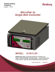
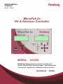
MicroPak 2e
HV & Atomizer Controller
MODEL:
A13338
IMPORTANT: Before using this equipment, carefully read
SAFETY PRECAUTIONS, starting on page 1, and all instructions
in this manual. Keep this Service Manual for future reference.
Service Manual Price:
$50.00 (U.S.)
NOTE: This is the first release of this manual.
LN-9624-00
MicroPak 2e HV Controller- Contents
CONTENTS
MicroPak 2e HV Controller
PAGE
SAFETY:
1-7
SAFETY PRECAUTIONS ......................................................................................................... 1
HAZARDS / SAFEGUARDS................................................................................................... 2-7
INTRODUCTION:
8-11
GENERAL DESCRIPTION ........................................................................................................ 8
SPECIFICATIONS ................................................................................................................. 8-9
PASSWORD PROTECTION ................................................................................................... 10
OPERATOR INTERFACE .................................................................................................. 10-11
INSTALLATION:
12-19
LOCATION / MOUNTING ....................................................................................................... 12
POWER CONNECTIONS ....................................................................................................... 13
ETHERNET CONNECTIONS.................................................................................................. 13
CASCADE CONNECTIONS.................................................................................................... 14
ELECTRICAL NOISE / GROUNDING ................................................................................ 14-15
WIRING EXAMPLES ......................................................................................................... 15-17
INTERLOCK CONNECTIONS ................................................................................................ 18
OPERATION:
20-41
START-UP .............................................................................................................................. 20
BASIC MENU OPERATIONS.................................................................................................. 21
RUN MENUS ..................................................................................................................... 22-23
CONFIGURATION MENUS ............................................................................................... 23-27
DIAGNOSTIC MENU ......................................................................................................... 27-28
OPERATING PARAMETERS AND SETTINGS.................................................................. 28-29
CONFIGURATION PARAMETERS AND SETTINGS ......................................................... 30-31
CONTROL AND STATUS CONDITIONS ........................................................................... 32-34
ETHERNET/IP INTERFACE .............................................................................................. 35-40
INTEGRATION NOTES:
58-59
GUIDELINES ..................................................................................................................... 56-57
MAINTENANCE:
58-60
TROUBLESHOOTING GUIDE ................................................................................................ 58
FAULT TROUBLESHOOTING GUIDE .................................................................................... 59
PARTS:
60-61
PARTS LIST ........................................................................................................................... 60
APPENDIX:
62-63
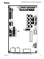
Mounting Diagrams, Atomizer Jumpers ................................................................................... 63
WARRANTY POLICIES:
64-65
LIMITED WARRANTY............................................................................................................. 64
LN-9624-00
MicroPak 2e Atomizer Controller- Contents
CONTENTS — MicroPak 2e Atomizer Controller
PAGE
INTRODUCTION:
42-45
ATOMIZER DESCRIPTION .................................................................................................... 42
SPECIFICATIONS ............................................................................................................. 42-43
SPEED CONTROL ............................................................................................................ 44-45
OPERATION:
46-57
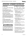
OPERATING MODES / AUTOMATIC SHUTDOWN................................................................ 46
INTERFACING CONSIDERATIONS ....................................................................................... 47
ETHERNET/IP INTERFACE .............................................................................................. 47-53
HARDWARE SIGNALS ...................................................................................................... 54-56
LN-9624-00
MicroPak 2e HV Controller - Safety
SAFETY
SAFETY PRECAUTIONS
Before operating, maintaining or servicing any
Ransburg electrostatic coating system, read
and understand all of the technical and safety
literature for your Ransburg products. This
manual contains information that is important
for you to know and understand. This information relates to USER SAFETY and PREVENTING EQUIPMENT PROBLEMS. To help
you recognize this information, we use the following symbols. Please pay particular attention
to these sections.
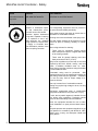
A WARNING! states information to alert you
to a situation that might cause serious injury if instructions are not followed.
A CAUTION! states information that tells
how to prevent damage to equipment or
how to avoid a situation that might cause
minor injury.
A NOTE is information relevant to the procedure in progress.
While this manual lists standard specifications
and service procedures, some minor
deviations may be found between this
literature and your equipment. Differences in
local codes and plant requirements, material
delivery requirements, etc., make such
variations inevitable. Compare this manual with
your system installation drawings and
appropriate Ransburg equipment manuals to
reconcile such differences.
!
WARNING
The user MUST read and be familiar
with the Safety Section in this manual and
the Ransburg safety literature therein
identified.
This manual MUST be read and thoroughly understood by ALL personnel who
operate, clean or maintain this equipment!
Special care should be taken to ensure that
the WARNINGS and safety requirements
for operating and servicing the equipment
are followed. The user should be aware of
and adhere to ALL local building and fire
codes and ordinances as well as NFPA-33
SAFETY STANDARD, LATEST EDITION,
prior to installing, operating, and/or servicing this equipment.
!
WARNING
The hazards shown on the following
pages may occur during the normal use
of this equipment. Please read the hazard chart beginning on page 2.
Careful study and continued use of this manual
will provide a better understanding of the
equipment and process, resulting in more efficient operation, longer trouble-free service and
faster, easier troubleshooting. If you do not
have the manuals and safety literature for your
Ransburg system, contact your local
Ransburg representative or Ransburg.
LN-9624-00
1
MicroPak 2e HV Controller - Safety
AREA
HAZARD
SAFEGUARDS
Tells where hazards
may occur.
Tells what the hazard is.
Tells how to avoid the hazard.
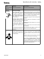
Spray Area
Fire Hazard
Improper or inadequate opera- Fire extinguishing equipment must be present in
tion and maintenance proce- the spray area and tested periodically.
dures will cause a fire hazard.
Spray areas must be kept clean to prevent the acProtection against inadvertent cumulation of combustible residues.
arcing that is capable of causing
Smoking must never be allowed in the spray area.
fire or explosion is lost if any
safety interlocks are disabled The high voltage supplied to the atomizer must be
during operation. Frequent Pow- turned off prior to cleaning, flushing or mainteer Supply or Controller shut- nance.
down indicates a problem in the
When using solvents for cleaning:
system requiring correction.
Those used for equipment flushing should
have flash points equal to or higher than those
of the coating material.
Those used for general cleaning must have
flash points above 100°F (37.8°C).
Spray booth ventilation must be kept at the rates
required by NFPA-33, OSHA, country, and local
codes. In addition, ventilation must be maintained during cleaning operations using flammable
or combustible solvents.
Electrostatic arcing must be prevented. Safe
sparking distance must be maintained between the
parts being coated and the applicator. A distance
of 1 inch for every 10KV of output voltage is required at all times.
Test only in areas free of combustible material.
Testing may require high voltage to be on, but only
as instructed.
Non-factory replacement parts or unauthorized
equipment modifications may cause fire or injury.
If used, the key switch bypass is intended for use
only during setup operations. Production should
never be done with safety interlocks disabled.
Never use equipment intended for use in waterborne installations to spray solvent based materials.
The paint process and equipment should be set up
and operated in accordance with NFPA-33, NEC,
OSHA, local, country, and European Health and
Safety Norms.
2
LN-9624-00
MicroPak 2e HV Controller - Safety
AREA
HAZARD
Tells where hazards Tells what the hazard is.
may occur.
Spray Area
SAFEGUARDS
Tells how to avoid the hazard.
Explosion Hazard
Improper or inadequate opera- Electrostatic arcing must be prevented. Safe
tion and maintenance proce- sparking distance must be maintained between the
dures will cause a fire hazard.
parts being coated and the applicator. A distance
of 1 inch for every 10KV of output voltage is reProtection against inadvertent
quired at all times.
arcing that is capable of causing
fire or explosion is lost if any
Unless specifically approved for use in hazardous
safety interlocks are disabled
locations, all electrical equipment must be located
during operation.
outside Class I or II, Division 1 or 2 hazardous
Frequent Power Supply or Con- areas, in accordance with NFPA-33.
troller shutdown indicates a
problem in the system requiring Test only in areas free of flammable or combuscorrection.
tible materials.
The current overload sensitivity (if equipped)
MUST be set as described in the corresponding
section of the equipment manual. Protection
against inadvertent arcing that is capable of
causing fire or explosion is lost if the current overload sensitivity is not properly set. Frequent
power supply shutdown indicates a problem in the
system which requires correction.
Always turn the control panel power off prior to
flushing, cleaning, or working on spray system
equipment.
Before turning high voltage on, make sure no objects are within the safe sparking distance.
Ensure that the control panel is interlocked with the
ventilation system and conveyor in accordance
with NFPA-33, EN 50176.
Have fire extinguishing equipment readily available
General Use and
Maintenance
Improper operation or mainte- Personnel must be given training in accordance
nance may create a hazard.
with the requirements of NFPA-33, EN 60079-0.
Personnel must be properly Instructions and safety precautions must be read
trained in the use of this equip- and understood prior to using this equipment.
ment.
Comply with appropriate local, state, and national
codes governing ventilation, fire protection, operation maintenance, and housekeeping. Reference
OSHA, NFPA-33, EN Norms and your insurance
company requirements.
LN-9624-00
3
MicroPak 2e HV Controller - Safety
AREA
HAZARD
SAFEGUARDS
Tells where hazards
may occur.
Tells what the hazard is.
Tells how to avoid the hazard.
Spray Area /
High Voltage
Equipment
Electrical Discharge
There is a high voltage device
that can induce an electrical
charge on ungrounded objects
which is capable of igniting coating materials.
Parts being sprayed and operators in the spray
area must be properly grounded.
Parts being sprayed must be supported on conveyors or hangers that are properly grounded. The
resistance between the part and earth ground must
Inadequate grounding will cause not exceed 1 meg ohm. (Refer to NFPA-33.)
a spark hazard. A spark can
ignite many coating materials
Operators must be grounded. Rubber soled insuand cause a fire or explosion.
lating shoes should not be worn. Grounding straps
on wrists or legs may be used to assure adequate
ground contact.
Operators must not be wearing or carrying any
ungrounded metal objects.
When using an electrostatic handgun, operators
must assure contact with the handle of the applicator via conductive gloves or gloves with the palm
section cut out.
NOTE: REFER TO NFPA-33 OR SPECIFIC
COUNTRY SAFETY CODES REGARDING
PROPER OPERATOR GROUNDING.
All electrically conductive objects in the spray area,
with the exception of those objects required by the
process to be at high voltage, must be grounded.
Grounded conductive flooring must be provided in
the spray area.
Always turn off the power supply prior to flushing,
cleaning, or working on spray system equipment.
Unless specifically approved for use in hazardous
locations, all electrical equipment must be located
outside Class I or II, Division 1 or 2 hazardous
areas, in accordance with NFPA-33.
4
LN-9624-00
MicroPak 2e HV Controller - Safety
AREA
HAZARD
SAFEGUARDS
Tells where hazards
may occur.
Tells what the hazard is.
Tells how to avoid the hazard.
Electrical
Equipment
Electrical Discharge
High voltage equipment is utilized in the process. Arcing in
the vicinity of flammable or
combustible materials may occur. Personnel are exposed to
high voltage during operation
and maintenance.
Unless specifically approved for use in hazardous
locations, the power supply, control cabinet, and all
other electrical equipment must be located outside
Class I or II, Division 1 and 2 hazardous areas in
accordance with NFPA-33 and EN 50176.
Turn the power supply OFF before working on the
equipment.
Protection against inadvertent
arcing that may cause a fire or Test only in areas free of flammable or combusexplosion is lost if safety circuits tible material.
are disabled during operation.
Testing may require high voltage to be on, but only
Frequent power supply shut- as instructed.
down indicates a problem in the
system which requires correc- Production should never be done with the safety
tion.
circuits disabled.
An electrical arc can ignite coat- Before turning the high voltage on, make sure no
ing materials and cause a fire or objects are within the sparking distance.
explosion.
Toxic Substances
Chemical Hazard
Certain materials may be harm- Follow the requirements of the Material Safety
ful if inhaled, or if there is con- Data Sheet supplied by coating material manufactact with the skin.
turer.
Adequate exhaust must be provided to keep the
air free of accumulations of toxic materials.
Use a mask or respirator whenever there is a
chance of inhaling sprayed materials. The mask
must be compatible with the material being
sprayed and its concentration. Equipment must be
as prescribed by an industrial hygienist or safety
expert, and be NIOSH approved.
LN-9624-00
5
MicroPak 2e HV Controller - Safety
AREA
HAZARD
SAFEGUARDS
Tells where hazards
may occur.
Tells what the hazard is.
Tells how to avoid the hazard.
Spray Area
Explosion Hazard—
Incompatible Materials
Halogenated hydrocarbon solvents for example: methylene
chloride and 1,1,1,Trichloroethane are not chemically compatible with the aluminum that might be used in many
system components. The
chemical reaction caused by
these solvents reacting with aluminum can become violent and
lead to an equipment explosion.
6
Aluminum is widely used in other spray application
equipment - such as material pumps, regulators,
triggering valves, etc. Halogenated hydrocarbon
solvents must never be used with aluminum equipment during spraying, flushing, or cleaning. Read
the label or data sheet for the material you intend
to spray. If in doubt as to whether or not a coating
or cleaning material is compatible, contact your
coating supplier. Any other type of solvent may be
used with aluminum equipment.
LN-9624-00
MicroPak 2e HV Controller - Safety
NOTES
LN-9624-00
7
MicroPak 2e HV Controller - Introduction
INTRODUCTION—HV CONTROLLER
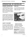
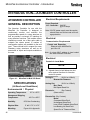
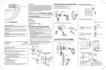
GENERAL DESCRIPTION
DISPLAYS
The Ransburg MicroPak 2e (A13338-00), in
conjunction with an appropriate cascade is
used to provide high voltage for electrostatic
application equipment. The controller is
packaged in a single package measuring 5.1”
tall X 8.5” wide X 6.5” deep. The controller can
operate in “Local” and “Remote” conditions
with either “Voltage Mode” or “Current Mode”
of high voltage control.
The front panel displays the high voltage
and current output from the cascade as true
readings. They are derived from feedback
signals in the low voltage cable between the
controller and the cascade.
The Ransburg MicroPak 2e Controller uses a
combination of proven high voltage generation
technology including microprocessor-based
control with diagnostic and communication
functions. It uses a variable voltage output to
drive a cascade that amplifies the voltage to a
high value. It also uses both current and
voltage feedback information to maintain the
desired set point. The processor circuitry
provides the maximum in applicator transfer
efficiency, while maintaining the maximum
safety
SAFETY FEATURES
When used with the appropriate applicators
and cascades, the Ransburg MicroPak 2e
Controller provides the ultimate in operational
safety. The protections include Overvoltage,
Overcurrent,
Di/Dt
and
Dv/Dt.
The
microprocessor circuits allow the use of output
load curve control, which limits the high
voltage output to safe levels when the controls
are set responsibly and safe distances are
observed and followed.
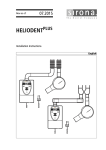
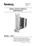
Figure 1: MicroPak 2e Controller
SPECIFICATIONS
(At Sea-Level Conditions)
Environmental / Physical
Operating Temperature:
0°C to +55°C
Storage and Shipping
Temperature:
-40°C to +85°C
Humidity:
95% Non-Condensing
Physical Size: 5.1" tall X 8.5" wide X 6.5" deep
8
LN-9624-00
MicroPak 2e HV Controller - Introduction
Electrical Requirements
Power Required:
(per controller)
J11 - Controller : 24V DC @ 0.5 Amps
J4 - Cascade:
24V DC @ 6.0 Amps
(fully loaded output),
RansPak 1000 (RP1000
or LEPS5002) Cascade
24V DC @ 2.0 Amps
(fully loaded output),
HP404, RP404, HP505
and CONSOLIDATED
Cascades
Note: 24V DC power supply must be regulated and have over current and over voltage protection.
Electrical
Communication Requirements
Control and Reporting: EtherNet/IP
Note: A unique MAC address is hard coded
into each MicroPak 2e & Atomizer Controller. User controls must be configured
to recognize each unique address.
Internal Controller
Scan Time:
1 msec
(all data is taken
from a rolling average of
16 scans)
HP404 / RP404 Cascades
Output:
100 kV @ 0 μA
125 μA @ 0 kV
Cascade Size:
HP404 1.50” X 1.56” x 7.0”
RP404 4” X 4” X 12”
RP1000 / LEPS5002 Cascades
Controls:
High Voltage Power :
24 Volts, 10Amp, Form C
relay contact
Output:
100 kV @ 0 μA
1000 μA @ 0 kV
Discrete In:
Cascade Size:
RP1000 4” X 4” X 12”
LEPS5002 17”x13”x13”
Discrete Out:
(Dry Contact)
Remote Stop
Misc IO Interlock/Trigger
Door Interlock
Booth Air Interlock
(Analog)
KV Setpoint (0-10VDC)
(3, Dry Contact)
Interlock Out
External Power Enable
System Alarm
Controller Operating Range
High Voltage:
0-100kV, settable in 1kV
increments
Current:
HP404/RP404
CONSOLIDATED
HP505
RP1000
LEPS5002
LN-9624-00
0-125 microamps
0-150 microamps
0-240 microamps
0-1000 microamps
0-1000 microamps
HP505 Cascade
Output:
100 kV @ 0 μA
240 @ 0 kV
Cascade Size:
1.50” X 1.56” x 7.0”
CONSOLIDATED Cascade
Output:
100 kV @ 0 μA
150 μA @ 0 kV
Cascade Sizes:
A12760-02
(IN LINE)
3” X 3” x 16.97”
A12761-02
3” X 7.64” x 11.8”
(RGT ANGLE)
9
MicroPak 2e HV Controller - Introduction
PASSWORD PROTECTION
MicroPak 2e Controller parameters
are
password protected with three levels, Config,
System and User to help prevent unqualified
operators from changing the values.
The
password menu is composed of two screens.
The first screen prompts the user to confirm
they wish to enter the required password, while
the second screen accepts the entry of the
password digits. The three levels represent a
hierarchy with Config at the top, System in the
middle and User at the bottom. This means
that while a higher level password is active, the
user will not be required to enter a lower level
password if they change a parameter which
requires it.
ATOMIZER
System Password Menu
Enter Password0000
Exit
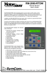
Figure 2: 1st Password Screen
HIGH VOLTAGE
Value=0000
Range 0000 to 9999
- Null0Save Quit
Digit Mode
Figure 3: 2nd Password Screen
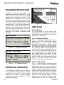
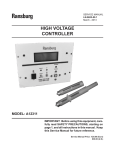
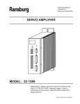
OPERATOR INTERFACE
The MicroPak 2e Controller shown in figure 4,
has a physically simple operator interface
consisting of five (5) LED's (Light Emitting
Diodes), four (4) switches, seven (7) buttons,
and two four line twenty character (4 X 20)
alpha/numeric displays.
10
Figure 4: Operator Interface
SWITCHES
Power Switch
The rocker switch on the left and the LED
directly above it are for power On/Off selection
and display. The green LED is on when the
power is On to the controller.
Local / Remote Switch
This is a two position toggle switch used to
determine if the Local (Front Panel) controls
have priority or if the Remote controls
(EtherNet/IP Connection or Discrete inputs)
have priority. If the switch is up (Local Mode)
the Front Panel controls may change parameters, enable or disable the high voltage, and
clear faults. The Remote EtherNet/IP connection may look at parameters and values, but
may not change them or enable/disable the
high voltage output. If the switch is down
(Remote Mode) the opposite is true except that
the Front Panel switch may be changed to local
Mode at any time to disable the Remote
Controls and to enable the Local Controls.
HV On / Off Switch
This is a return-to-center momentary toggle
switch. It is active only when the Local/Remote
mode switch is set to Local. It is used to
enable and disable the High Voltage output and
to clear system faults. When the System
Checks and Current Status are OK, flipping the
switch to the up position (HV On) will enable
High Voltage Output (see "Figure 4 - Operator
Interface" in this section). Flipping it to the
down position (HV Off) will disable the High
Voltage Output. If there is a system fault,
LN-9624-00
MicroPak 2e HV Controller - Introduction
flipping this switch to the OFF position (also
known as the Reset position) will reset (clear)
any faults currently detected by the system.
Atomizer On / Off Switch
This is a two position toggle switch. It is used
to enable and disable (i.e. start and stop) a
configured atomizer when in LOCAL mode.
When the controller is in REMOTE mode it is
ignored.
LED'S
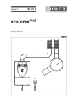
Figure 5: Buttons
Power LED
HV/AT Button
If the Green Power LED is on, then the system
power to the controller is On.
The High Voltage/Atomizer Button (just below
the right display) is used to toggle the active
display between the “Atomizer” and “High
Voltage” displays. Note that the active display
always has a (block character) in the lower
right corner. So when the High Voltage is the
active display, it will look like "Figure 3 - 2nd
Password Screen" in the PASSWORD PROTECTION section.
HV Fault LED
The red HV Fault LED is lit when the system
detects a fault condition (see "Figure 4 Operator Interface" in the SWITCHES section).
When operating in "Local Mode", it is cleared
by flipping the HV On/Off switch to the OFF
(Reset) position. If the system is still in a fault
condition, it will immediately be lit as the system
detects the fault.
High Voltage LED
The green High Voltage LED displays the
current state of the High Voltage Output. This
LED is illuminated whenever High Voltage is
being supplied.
Atomizer Fault LED
The red Atomizer Fault LED is lit when the
Atomizer subsystem detects a fault condition.
This condition will be displayed on the Atomizer
status screen.
Atomizer LED
The green Atomizer LED is lit when the Atomizer controller commands the turbine to spin.
BUTTONS
The seven buttons used to control the viewing
and entry of information on the two 4 X 20
character displays are:
LN-9624-00
Screen Button
The Screen Button (just below the right display)
is used to change (toggle) to the next Menu
screen. The menu screens wrap around so that
after the last screen it will return to the first
screen.
Up and Down Buttons
The buttons above and below the Set Button in
the middle (the Up and Down Buttons) are used
to move the selection indicator vertically to a
value to be selected by the Set Button. When
in a value entry menu, the Up and Down
buttons are used to increase or decrease the
value being entered.
Set Button
This labeled button (in the middle) is used to
select the value to change and to enter the
change after it has been made.
Left and Right Buttons
The buttons to the right and left of the Set
Button (the Left and Right Buttons) are used to
move the selection horizontally.
11
MicroPak 2e HV Controller - Installation
INSTALLATION
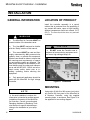
GENERAL INFORMATION
LOCATION OF PRODUCT
Install the controller assembly in a control
cabinet that is protected from the possibility of
any contact with water, vapor or high humidity.
Ambient temperature should not exceed 131F
(55C). The area should be clean, dry and well
ventilated.
!
WARNING
The MicroPak 2e Controller MUST be
located outside of the hazardous area.
The User MUST read and be familiar
with the “Safety” section of this manual.
This manual MUST be read and thoroughly understood by ALL personnel who
operate, clean, or maintain this equipment!
Special care should be taken to ensure that
the warnings and requirements of operating and servicing safely are followed. The
user should be aware of and adhere to ALL
local building and fire codes and ordinances as well as NFPA-33, OSHA, and all related country safety codes prior to installing, operating, and/or servicing this
equipment.
Only approved applicators should be
used with the MicroPak 2e High Voltage
Controller.
!
CAUTION
DO NOT locate the Controller near or
adjacent to heat producing equipment such
as ovens, high wattage lamps, etc.
Figure 6: Installation
MOUNTING
NOTE
As each installation is unique, this
information is intended to provide general
installation information for the MicroPak
2e Controller. Consult your authorized
Ransburg distributor or Ransburg Technical Service for specific directions pertaining to the installation of your equipment.
12
Using eight (8) #4-40 or M3 screws (not included), secure the front panel of the MicroPak 2e
& Atomizer Controller, using the supplied
mounting holes, to enclosure. See Figure 43 in
the appendix for a mounting diagram.
LN-9624-00
MicroPak 2e HV Controller - Installation
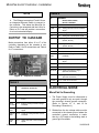
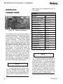
INPUT POWER
CONNECTIONS
Tables 1 & 2 show the connections for Cascade and Controller power.
Input power must be supplied from one or two
regulated DC power supplies. Two connectors, J4 and J11 are provided so that controller
operating power may be separated from
cascade operating power. Cascade operating
power is delivered through J4 and controller
operating power is delivered through J11.
This configuration gives the user the ability to
provide an ESTOP by inserting a suitable
switch or contactor in the J4 power leads.
When separate control of the cascade power
is not required, power to J4 and J11 can be
run from one DC power supply.
!
CAUTION
Power supplies connected to J4 and
J11 must be protected against excessive
current and provide Over Voltage protection.
TABLE 2
Signal
Name
J11
Connection
Power Supply
+VPWR
Pin 1
+ 24 VDC
GND
Pin 2
DC return
N.C.
Pin 3
N.C.
NOTE
The Ransburg MicroPak 2e Controller
has a built in resettable fuse in the controller
power lead, so if the controller logic draws a
current in excess of 1.5 amps it will open.
Reset is achieved by turning controller power OFF for 5 minutes then back ON.
ETHERNET CONNECTORS
Figure 7: Input Power Connections
TABLE 1
Figure 8: Ethernet Connector
Signal
Name
J4
Connection
Power Supply
+VPWR
Pin 1
+ 24 VDC
+VPWR
Pin 2
+ 24 VDC
GND
Pin 3
DC return
GND
Pin 4
DC return
CHGND
Pin 5
Earth Ground
LN-9624-00
Use the appropriate 10/100BASE-T Ethernet
wiring (Straight EIA/TIA 568A) for your installation with an RJ-45 plug to connect to the MicroPak 2e Controller. Connection can be made
using either J7 or J10 as shown in Figure 8
above.
13
MicroPak 2e HV Controller - Installation
NOTE
TABLE 4
J7
The Ethernet connectors J7 and J10 use
an integrated Ethernet Switch to connect to
the controller. This allows the MicroPak 2e
Controller to be networked with the LAN of a
Robot or PLC and still provide a connection
for a local networked display.
OUTPUT TO CASCADE
Make connections from either J6 or J7 of the
controller, depending on the cascade in use.
Refer to Table 3 for J6 connections and Table 4
for J7 connections.
Cascades
HP404, RP404, HP505,
RP1000, LEPS5002
HVGND
Pin 1
0 VDC for VCT Power
AFB
Pin 2
Analog Cascade Current Feedback
Signal
VCT
Pin 3
Analog DC Cascade Drive Signal
VCT
Pin 4
Analog DC Cascade Drive Signal
HP_DR B
Pin 5
Digital Cascade Drive Signal
(HP404, HP505)
HP_DR A
Pin 6
Digital Cascade Drive Signal
(HP404, HP505)
N.C.
Pin 7
(Termination point; No Connection)
N.C>
Pin 8
(Termination point; No Connection)
MULTIGND
Pin 9
0 VDC for Analog Cascade Voltage
Feedback
KVFB
Pin 10 Analog Cascade Voltage Feedback
Signal
N/C
Pin 11 (Termination point; No Connection)
HVGND
Pin 12 0 VDC for VCT Power
RP DR B Pin 13 Digital Cascade Drive Signal
(RP1000, LEPS5002)
Figure 9: Outputs to Cascade
TABLE 3
J6
Cascades
VCT/R+
Pin 2
Analog DC Cascade Drive Signal
Nominal 15 VDC for Cascade Electronics
SAFEPin 4 0 VDC for Analog Cascade Voltage
TY /GND
Feedback
14
Analog Cascade Voltage Feedback
Signal
SHIELD/ Pin 6
GND
0 VDC for Analog Cascade Current
Feedback
AFB/
I-FB
Analog Cascade Current Feedback
Signal
Pin 7
HVGND
Pin 16 0 VDC for VCT Power
MicroPak 2e Grounding
0 VDC for R+ and E+ Power
Pin 5
Pin 15 0 VDC for VCT Power
ELECTRICAL NOISE
Pin 1
KVFB/
V-FB
HVGND
A12760-02 / A12761-02
HVGND
+15V/E+ Pin 3
RP DR A Pin 14 Digital Cascade Drive Signal
(RP1000, LEPS5002)
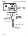
1. The Power Supply must be referenced to
true earth ground at only one point, through
the controller’s chassis ground connection.
(Refer to Figures 10, 11, and 12 for
Grounding Connections.)
2. Shields from the low voltage cable must be
connected to the chassis ground where the
controller’s ground connection is made,
then by a 3/4” braid to the building steel or
ground grid if available.
LN-9624-00
MicroPak 2e HV Controller - Installation
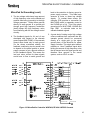
MicroPak 2e Grounding (cont.)
3. The low voltage cable has a large amount
of high frequency noise on the shields and
grounds from being in proximity to the high
voltage generator. Taking these grounds
directly to earth ground or a ground grid
through good high frequency conductors
(braid) keeps this high frequency noise
from interfering with the low voltage control
circuitry.
4. The feedback signals for kV and A are
developed with respect to the cascade
ground signal (MULTIGND). If the cascade
ground were routed only to earth ground
via the above mentioned shields, the
feedback conditioning circuitry would have
to depend on the panel ground or power
supply common to get a ground reference
for the feedback signals. This means the
low level return current for these signals
would have to flow to earth ground and
back to the controller via factory ground or
power supply common. This adds large
amounts of noise to these low voltage
signals. To combat these effects, the
controller PCB provides a connection for
MULTIGND which is separately routed to
the CHGND pin of J4. This is the single
ground point for MULTIGND, HVGND and
logic GND to minimize noise on the
cascade feedback signals.
5. A great deal of testing under high voltage
corona conditions has confirmed that this
cascade ground should be connected
directly at a single point to the signal
ground plane of the MicroPak 2e power
supply controller. This single point method
maintains a “clean” feedback signal while
limiting the amount of high frequency noise
that is dumped onto the signal ground and
therefore other grounds in the overall
system, such as a PLC or robot.
3/4" BRAID CABLE
EARTH GROUND
Figure 10: MicroPak 2e Controller W/HP404, RP-404 & HP505 Cascade
LN-9624-00
15
MicroPak 2e HV Controller - Installation
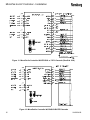
3/4" BRAID CABLE
EARTH GROUND
Figure 11: MicroPak 2e Controller W/LEPS5002 or 74793 Cascade (RansPak 1000)
Figure 12: MicroPak 2e Controller W/CONSOLIDATED Cascade
16
LN-9624-00
MicroPak 2e HV Controller - Installation
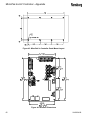
Figure 13: Proper Power Supply and Grounding Connections
LN-9624-00
17
MicroPak 2e HV Controller - Installation
INTERLOCK
CONNECTIONS
Table 5 shows the pin assignments for the interlock signals.
TABLE 5
Outputs
J5
External Power Enable
Pins 1, 2
System Alarm Out
Pins 3, 4
Interlock Out
Pins 5, 6
Interlock Inputs
Figure 14: Interlock Connector
J5 is supplied to give the end-user access to
interlock connections for integrating the controller into the user’s system. Three output signals
are provided thru dry contacts (rated 30 VDC @
2 amps maximum).
These three signals
indicate: 1) the state of controller operating
power, 2) when a controller fault exists, and 3)
the state of the controller interlock inputs. Four
input signals are provided which should only be
connected to dry contact outputs from the
user’s system. The four interlock signals are
designated as: 1) a door interlock, 2) a booth
air interlock, 3) a miscellaneous interlock, which
can be configured to serve as a HV Trigger
input, and 4) a remote stop input which removes power from the cascade drive circuits
when sensed by the Display and Communications Processor. A fifth input which accepts a
0-10 VDC analog control signal is provided to
allow control of the high voltage setpoint.
NOTE
The fourth interlock input Remote Stop
cannot be disabled through software. If the
user does not wish to use the Remote Stop
input, a jumper must be placed between J513 and J5-14 to close the Remote Stop circuit.
18
Door Interlock (+)
Pins 7 *
Door Interlock (-)
Pins 8
Booth Air Interlock (+)
Pins 9 *
Booth Air Interlock (-)
Pins 10
Misc.Interlock/Trigger(+) Pins 11 *
Misc. Interlock/Trigger(-) Pins 12
Remote Stop (+)
Pins 13 *
Remote Stop (-)
Pins 14
Analog Input
KV Setpoint (+)
Pins 15
KV Setpoint (Gnd)
Pins 16
* Refer to the following note.
NOTE
The positive interlock input pins are directly connected to the internal +24VDC of
the MP2e controller. It is recommended that
these pins not be run outside of the MP2e
enclosure without the addition of series limiting resistors (3.3K, 1/4w). This will prevent
overloading the MP2e internal current limit if
a positive input is accidentally shorted to
ground. Alternatively, the user can provide
a separate +24VDC supply external to the
MP2e to power the (-) interlock inputs.
LN-9624-00
MicroPak 2e HV Controller - Installation
NOTES
LN-9624-00
19
MicroPak 2e HV Controller - Operation
OPERATION — HV Controller
HIGH VOLTAGE
START-UP
Before its’ first use, the following features of the
MicroPak 2e controller must be configured by
the user.
If the EtherNet/IP interface will be used, it
must be enabled.
A valid IP address for EtherNet/IP use.
NOTE
The MicroPak 2e controller will come
preconfigured from the factory for the following: 1) The type of cascade to be driven, 2)
whether an Atomizer Controller is included
or not and 3) the Atomizer type supported
when an Atomizer Controller is included..
In addition if an Atomizer Controller is present,
the user must configure the following features
of the Atomizer Controller.
The type of each signal being supplied to
the seven analog inputs of the Atomizer
controller. i.e. Voltage (0-10 V) or Current
(4-20mA).
NOTE
For correct operation of the analog inputs, jumpers JMP15 through JMP9 on the
Atomizer Controller must also be set to the
matching V or I mode. See the section on
Atomizer operation for further details.
Ransburg
SN 1330-0021
©2014
Software Ver: 1.0.00
Figure 15: Start-Up Menu Screen (Left)
The ATOMIZER screen allows the user to
select from one of three options: RUN mode,
Configuration mode, or Diagnostics mode. In
addition, the bottom line displays the status of
the system connections.
ATOMIZER
Run
Configuration
Diagnostics
HVC eip
Figure 16: Start-Up Menu Screen (Right)
The status is displayed via upper or lower case
letters which indicate the associated board is
communicating (upper case) or not communicating (lower case). The letters “HVC” represents the High Voltage Control board and the
letters “EIP” represent the EtherNet/IP host
connection. If the configuration includes an
Atomizer Controller the letters “AT” will be
shown.
NOTE
START-UP MENU
The two menus that display on the unit at
power up are shown in Figures 15 and 16. The
HIGH VOLTAGE screen displays the Serial
Number, Copyright Date and Software Version
of the unit.
20
When the REMOTE/LOCAL switch is
set to REMOTE at power-up, the controller
automatically switches to RUN mode after
approximately 5 seconds. When the REMOTE/LOCAL switch is set to LOCAL at
power-up, the controller remains in the startup screens until the user selects a mode.
LN-9624-00
MicroPak 2e HV Controller - Operation
MENUS AND OPERATION
On all of the menus, if a parameter can be
changed it will be proceeded by a blinking ““
and followed by a blinking “” to show that it is
a changeable value. If there is more than one
changeable value on a screen, pressing the Up
or Down and Left or Right Buttons will move the
selection " "s to the next value. If there are
no changeable values on a screen then the
“Active Screen Indicator” in the lower right
corner will blink. When the selection " "s
surround the value you wish to change, press
the Set Button. If the value to be changed
requires a password, either the User, System
or Config Password Menu will be displayed
allowing you to enter the required password.
After entering the Password, you are returned
to the originally selected value. If the password
was entered correctly, the value may now be
changed. If the entry was incorrect, the password screen will again be displayed. Once a
password has been successfully entered, it will
remain active for a period of time that depends
on the password type. It then times out and
must be re-entered to make further changes.
During the active time, the block character
indicating the active screen will alternate with
the letters U, S or C corresponding to entry of
the User, System or Config password. The
activated time period for these password types
decreases as the privilege level increases
(U = 4, S = 3 and C = 2 minutes).
When a numeric value is being changed, a
value change menu, similar to the one shown in
Figure 17, will be displayed. In this menu the
Left and Right Buttons allow the user to select
HIGH VOLTAGE
Value=0000
Range 0000 to 9999
Inc/DecDigitQuit
Figure 17: Value Change Screen
LN-9624-00
from the two methods available to change a
value.
If the Inc/Dec method is selected, the user is
shown the screen seen in Figure 18. In this
mode, the Up and Down buttons (above and
below the SET Button) can be used to incrementally change the value. The value will
increase with the up button and decrease with
the down button until it reaches the maximum
or minimum allowed value.
ATOMIZER
Value000
Range 000 to 100
Inc/Dec Mode
Figure 18: Inc/Dec Change Mode Screen
If the Digit method is selected, the user is
shown the screen seen in Figure 19. This
shows the current value to be modified, the low
and high limits for the selected parameter and
the digit mode options to change the current
value. The "-" option allows the user to negate
the current value displayed. The “Null” option
causes the current value to be cleared allowing
the user to begin entry of a new value. The
‘number’ option ("0") enables the Up and
Down Buttons to select the next digit to be
added to the value when the user presses the
Set Button. The “Save” option saves any
changes made in this screen and exits. And
the “Quit” option cancels any changed made in
the screen and exits.
ATOMIZER
Value=0000
Range 000 to 100
- Null0Save Quit
Digit Mode
Figure 19: Digit Mode Change Screen
21
MicroPak 2e HV Controller - Operation
High Voltage Fault Menu
RUN MENUS
High Voltage Run Menu
This menu displays the KVSet value in Voltage
Mode. Also displayed by this menu are the
control mode and cascade type, the current
actual KV value, the current μA value, the
current hardware check value, the High Voltage
status, and the current controller status. KVSet
is the only changeable value on this menu. In
Current Control Mode the menu displays μASet
as the changeable value instead of KVSet.
HIGH VOLTAGE
KVSet000
V404
KVAct 000 uAAct 0000
Chk:OK
Com: OK
HV: Off
Sts: STP
This menu displays the latest fault and any
current warning. It also provides an option to
SAVE the current parameter values as default
values. Selecting this option will cause the
current values to be stored so that they will be
available after a power cycle. If this option is
not used, all parameter changes are discarded
at the next power cycle when default parameters are restored.
HIGH VOLTAGE
Fault:HV Power Off
Warn: None
HVC EIP
SaveDefaults
Figure 22: Fault Menu Screen
User Password Menu
Figure 20: Run Menu Screen
When the password has been entered, the user
will be returned to the value being changed.
High Voltage Mode Menu
This menu displays whether or not the DiDt or
DvDt feature is enabled and the sensitivity of
this feature. If the current/voltage changes
greater than this value, within 100 milliseconds,
a fault occurs. The next element displayed on
this screen is a user settable limit on cascade
output current when in voltage control mode.
This limit has a range of 0 to the maximum
current for the currently configured cascade.
The last two items displayed are KV Low Limit
and KV High Limit which are used in Current
Mode to set a lower and upper bound, which if
exceeded will cause a fault to occur. All five of
these values can be selected and changed.
Note: KV Low Limit and KV High Limit are only
displayed when in Current Mode.
HIGH VOLTAGE
DiDt Mode Dis 50
Max UA Limit 0125
HIGH VOLTAGE
User Password Menu
Enter Password0000
Exit
Figure 23: Password Menu Screen
Atomizer Run and Fault Menu
When an atomizer is configured, this menu
displays the configured atomizer type on line 1,
followed by the Turbine Speed Set Point value
and the current actual Turbine Speed value. In
addition, the current Fault status of the Atomizer Controller and the current Bearing Air
pressure are displayed. If no atomizer is
configured, this screen shows the high voltage
controller’s fault and connection status information similar to figure 22.
Figure 21: Voltage Mode Screen
22
LN-9624-00
MicroPak 2e HV Controller - Operation
ATOMIZER
RMA300-500
kRPM-Sp 00 RPMAct 00
No Faults
Bearing Air 000 psi
Figure 24: Run Menu Screen (Right)
Atomizer Shape Air Menu
This menu allows the user to manually adjust
both the shaping air outputs and the paint flow
rate outputs. The values used are expressed
as percentages since the controller can be
configured to provide either 0-10 V or 4-20 mA
analog outputs.
ATOMIZER
ShapeAirSP1
ShapeAirSP2
PFlowRateSP1
PFlowRateSP2
000%
000 %
000 %
000 %
Automatic Gun Fault Menu
This menu displays the latest faults for both the
atomizer and high voltage controllers.
In
addition, it displays any current high voltage
warning and the current connection status.
ATOMIZER
ATf:RansNet CommLost
HVflt:HV Power Off
HVWrn:None
HV
AT
Figure 27: Gun Fault Menu Screen
CONFIGURATION MENUS
High Voltage Controller Configuration Menus
The following seven menus are displayed on
the HIGH VOLTAGE screen (left panel).
Figure 25: Shape Menu Screen
Atomizer Fluid Maintenance Menu
This menu enables the user to safely perform
paint flow calibration or flushing operations by
disabling the Fluid Interlocks. Disabling the
fluid interlocks cause both the high voltage and
atomizer to be disabled (forced off). While at
the same time allowing the paint and solvent
triggers to occur without checking the rotational
speed of the atomizer.
ATOMIZER
Atomizer Fluid Maint
** Remove CUP **
before Disabling
FluidInterlockEna
Figure 26: Atomizer Maint Menu Screen
LN-9624-00
Cascade Menu
This menu allows the factory to configure the
type of cascade connected to the controller.
HIGH VOLTAGE
Cascade HP404
MaxI 150 uA V 100 KV
Freq 67.5 kHz
Figure 28: Cascade Menu Screen
Interlock Menu
The three Interlock inputs which can be
enabled or disabled are configured in this
screen. As seen in Figure 29, the first interlock
is labeled MiscIO. This input can serve as
23
MicroPak 2e HV Controller - Operation
either an Interlock input (as shown in Figure
29) or as a Trigger input. It can be configured
to the trigger function by selecting Interlock
and pressing the Set button. It can similarly
be returned to the interlock function by selecting Trigger and pressing the Set button. The
other two inputs are dedicated to use as
interlocks and are labeled Door and Booth Air.
This screen has a total of four changeable
items.
HIGH VOLTAGE
MiscIOEnaInterloc
Booth Ena
Door
Ena
Figure 29: Interlock Menu Screen
NOTE
The system default to have all interlocks ENABLED. So if the interlocks are not wired
closed, the controller will remain in a faulted
condition.
The fourth interlock input Remote Stop
cannot be disabled. If the user does not wish
to use the Remote Stop input, a jumper must
be placed between J5-13 and J5-14 to close
the Remote Stop circuit.
MicroPak V-I Limiting Menu
This menu displays four settings that the
factory configures to match the product(s)
purchased with the controller. These settings
cannot be changed by the user.
The control mode indicates if the controller is
set to control Voltage or Current. The Charge
Type corresponds to how the high voltage
charge is transferred to the material being
applied. This is normally set as direct for all
cascades except the RP1000 when used with
24
an indirect charge ring, The V-I limiting
function is always enabled. It controls a
software function which limits the voltage and
current load curves to levels very similar to
those used in the original MicroPak controller.
HIGH VOLTAGE
Control ModeVoltag
Charge Type Direct
uPak VIlimiting Ena
SingleBell Cabinet
Figure 30: MicroPak V-I Limiting Screen
IP Address Menu
This menu provides the user with four options.
It allows setting the EtherNet/IP Address for
the controller, provides control over whether
EtherNet/IP communications are enabled or
not, provides control over whether DHCP is
used to acquire an IP address and allows the
user to save any Configuration changes that
have been made. Note that the Save or Quit
options will place the unit into run mode. This
is the only way to exit the Configuration
Menus other than cycling controller power.
HIGH VOLTAGE
IP192168:000:003
Ethernet IP Dis
DHCP Dis Hardware
QUIT SAVE
Figure 31: IP Address Menu Screen
When DHCP is disabled and a new IP Address has been entered and saved, power
must be cycled on the unit before the new IP
Address will be used.
When DHCP is enabled, the IP address,
network mask and Gateway IP address will be
LN-9624-00
MicroPak 2e HV Controller - Operation
requested from a local DHCP server. The
user is responsible for providing a server to
respond to these requests. If no DHCP server
is available the MicroPak 2e will wait indefinitely for a response.
In addition, when
DHCP is enabled, an EtherNet/IP controller
can configure the MicroPak 2e to save the
current configuration and use it at the next
power cycle instead of requesting an address
via DHCP. Similarly, the remote EtherNet/IP
controller can also reconfigure the MicroPak
2e to request its IP configuration from a DHCP
server at the next power cycle.
Feedback Fault Menu
This menu gives the user control over the use
of the Feedback Fault. It allows this fault to
be disabled and provides the means to modify
the delay before a fault is generated after
detection.
It also allows the user to modify the Communications Timeout value. The Communications
Time Out value has a range of 500—5000
milliseconds with a default value of 1000.
This parameter is used by the Display &
Communications Control processor to determine how long to wait before signaling a fault
when Ethernet/IP messages are not being
received.
HIGH VOLTAGE
Feedback FaultEna
FB Fault Delay 0500
ComTimeOut 1000 msec
QUIT SAVE
Figure 32: Feedback Menu Screen
NOTE
The Feedback Fault settings should
only be changed when adjacent indirect
charge applicators cause Feedback Faults.
In all other cases the defaults shown above
should be used.
LN-9624-00
Date Menu
This menu allows the user to set the date and
time for the controller’s real-time clock (RTC).
The RTC information is then used by the
controller to apply a timestamp to log file
entries. This is done to aid in later analysis.
As figure 33 shows, there are six settable
values on the date and time screen. Month,
Day, Year, Hours, Minutes and Seconds,
HIGH VOLTAGE
Date1126-2012
Time 10:08:30
QUIT SAVE
Figure 33: Date Screen
Change Passwords Menu
This menu requires the user to enter the
current password before they are allowed to
set a new password. When the new password is entered, it will immediately be used for
all values being changed.
HIGH VOLTAGE
Change Passwords:
User Password????
Sys Password ????
Cfg Password ????
Figure 34: Change Passwords Screen
Broadcast Control Menu
This menu allows the user to control the
filtering of excessive broadcast packets. The
principal use of this feature is as an aid in
confirming the presence of excessive broadcast traffic. Setting Suppression to Ena will
enable the removal of broadcast packets if the
count of packets per measurement interval
exceeds the percentage specified by Storm
Level. In normal use this feature should be
disabled.
In addition, the MAC address
25
MicroPak 2e HV Controller - Operation
assigned to the front board of the controller pair
is displayed at the top of the screen.
HIGH VOLTAGE
MAC00:50:C2:FA:D0:37
Broadcast Cntrl Menu
Suppression Dis
Storm Level
01 %
Figure 35: Broadcast Control Screen
ATOMIZER CONFIGURATION MENUS
The following three menus are displayed on the
ATOMIZER screen (right panel). They are
included in the base MicroPak 2e Controller but
are only used when an Atomizer Controller
board is configured.
Atomizer Use Menu
This menu shows the maximum number of
Atomizers which can be configured, the number
of Atomizers which have been configured, (as
previously mentioned, only one Atomizer
Controller is currently supported) and which
atomizer type was configured by the factory.
ATOMIZER
Max Atomizers 1
Num Atomizers0
Atomizer RMA300-500
Figure 36: Atomizer Use Screen
Min Bearing Air Menu
The Bearing Air menu is provided so that a
user can specify a lower than normal level of
bearing air to the turbine in a production
emergency.
26
!
CAUTION
Extreme caution should be used with
this setting as turbine failure can result
from specifying a lower value than the factory default setting. This requires the System Password to change.
NOTE
The factory default minimum value is
restored at each controller power cycle to
guard against forgetting the change was
made .
Analog Inputs Mode Menu
This screen allows the user to select the mode
of each analog input on the Atomizer Controller . Two options are available, “V” or “I”. “V”
represents a 0-10 volt input and “I” represents a
4-20 milliamp input.
ATOMIZER
Analog Input Mode
V=0-10V I=4-20mA
#1V#2 V #3 V #4 V
#5 V #6 V #7 V
Figure 37: Analog Input Mode Screen
NOTE
Jumpers JMP15 through JMP9 must be
set to match the selections on this screen.
See the Atomizer Controller operation section for further information.
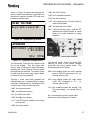
DIAGNOSTICS MENU
Selecting Diagnostics from the Startup Menu
LN-9624-00
MicroPak 2e HV Controller - Operation
shown in Figure 16 causes the following two
menu screens to be displayed. Note that once
this menu is entered, a power OFF cycle must
be done to exit the menu.
HIGH VOLTAGE
Keys=udlrcsaLoraE
“a H” -the HV/AT button.
“L R” -the Local/Remote switch.
“o O” -the HV On switch.
“r R” -the momentary HV off switch which is
used to Reset faults.
“a A” -the Atomizer on/off switch.
“E e” -the External stop input. Note the “E”
indicates the external contact is closed
which is the state required for normal
operation.
Figure 38: Diagnostic Key Screen
ATOMIZER
PWR=02820 LGIC=02685
1.8V=02320
Sts: STP
Figure 39: Diagnostic Voltage Screen
The first screen, Figure 38, only uses the first
line of the display. This line begins with
“Keys=“ and is followed by single characters
showing the current state of the front panel
push buttons and switches. This allows a user
to verify that all the front panel inputs, shown
in Figure 40, work as expected.
Figure 40: Front Panel Switches
The second screen, Figure 39 shows A2D
readings for three of the system voltages
along with the current system status. The
items displayed are as follows:
PWR—this reading shows the main cascade
power (+24V DC) connected to J4. It’s
nominal value is 2820.
Typically a lower case letter indicates the
corresponding key is inactive while an upper
case letter indicates activity. Working from left
to right across the list of letters we have:
LGIC—this reading shows the Logic power
(+24V DC) connected to J11.
It’s
nominal value is 2685.
“u U” -the Up arrow button.
1.8V—this readings shows the internal 1.8V
DC power supply. It’s nominal value is
2320.
“d D” -the Down arrow button.
“l L” -the Left arrow button.
“r R” -the Right arrow button.
Sts —this shows the current system state
which can be either Stopped or Faulted.
“c C” -the SET button. located in the Center
of the arrows.
“s S” -the Screen button.
LN-9624-00
27
MicroPak 2e HV Controller - Operation
OPERATING
PARAMETERS AND
SETTINGS
kVSet
This is the voltage setpoint, used in Voltage
Mode. The system attempts to keep the
voltage at this value when operating at low
current levels, but as the current level is
increased the voltage will be reduced to stay
within the I-V curve of the selected cascade.
When operating in Current Mode, kVSet is not
displayed since the upper and lower voltage
limits are determined by kV Low Limit and kV
High Limit.
μASet
This is the current setpoint, used in Current
Mode. The system attempts to keep the
current at this value.
di/dt Enable/Disable
This allows the user to enable or disable the
controller’s detection of rapid current changes.
This is only active and displayed in Voltage
Mode.
is greater than 90% of this value, it issues a
Current Limit Warning. When the current rises
above this value, it issues a Current Limit
Fault.
kV Low Limit
This parameter determines the level where a
kV Low Limit Fault occurs. When the Voltage
falls below this value, it issues a kV Lo Fault. It
only applies in Current Mode.
kV High Limit
This parameter determines the level where a
kV High Limit Warning occurs. When the
voltage exceeds 90% of this value, it issues a
kV High Limit Warning and prevents the
voltage from exceeding the limit value. It only
applies in Current Mode.
Turbine Speed Setpoint
This parameter sets the turbine speed which
will be commanded by the controller when in
LOCAL mode. When in Remote mode it
displays the speed setpoint commanded by
the remote controller.
NOTE
di/dt Sensitivity
When a rapid current change occurs where
current rises faster than this value in 100
milliseconds, a di/dt fault is generated. This is
only active and displayed in Voltage Mode.
dv/dt Enable/Disable
This allows the user to enable or disable the
controller’s detection of rapid voltage changes. This is only active and displayed in
Current Mode.
ShapeAirSP1
dv/dt Sensitivity
ShapeAirSP2
When a rapid voltage change occurs where
voltage falls faster than this value in 100
milliseconds, a dv/dt fault is generated. This is
only active and displayed in Current Mode.
This parameter determines the level in percent
(i.e. 0-100%) that will be applied to the Shaping Air 2 output.
Max μA Limit
This parameter determines the level in percent
(i.e. 0-100%) that will be applied to the Paint
This parameter determines the level where a
Current Limit Fault occurs. When the current
28
The following Atomizer settings and features are only available when .the Atomizer
Controller is configured for use with a ControlPak.
This parameter determines the level in percent
(i.e. 0-100%) that will be applied to the Shaping Air 1 output.
PFlowRateSP1
LN-9624-00
MicroPak 2e HV Controller - Operation
Flow Rate 1 output.
PFlowRateSP2
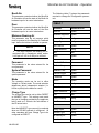
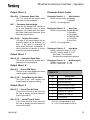
Table six lists the operating parameters and
the passwords required to change each
parameter.
This parameter determines the level in percent
(i.e. 0-100%) that will be applied to the Paint
Flow Rate 2 output.
TABLE 6
FluidInterLock
This parameter allows the user to disable the
fluid interlocks between the high voltage
controller and the atomizer controller. It is
intended to allow maintenance activities such
as paint flow calibrations. In addition, it can be
used in an emergency to allow flushing of an
atomizer when it cannot be run up to speed.
A description of the fluid interlocks follows:
There are two fluid interlocks implemented in
the Atomizer which this parameter enables or
disables. The first interlock normally prevents
the Atomizers Paint Trigger and Wash outputs
from being activated when the atomizer is
below a minimum safe speed for fluid application. The purpose of this interlock is to prevent fluid from being applied when it could
easily flood the turbine. The second interlock
prevents the solvent control output (i.e. Bell
Cup, Disk or Gun Wash) from activating when
the high voltage controller is active. This is
done to minimize the risk of a fire caused by a
high voltage discharge while solvent fluid is
present.
LN-9624-00
Parameter
Password Level
KvSet
-none-
uASet
-none-
Di/Dt Enable
User
Di/Dt Sensitivity
User
Dv/Dt Enable
User
Dv/Dt Sensitivity
User
Max μA Limit
System
KV Low Limit
-none-
KV High Limit
System
Turbine Speed Setpoint -noneShaping Air 1
User
Shaping Air 2
User
Paint Flow Rate 1
User
Paint Flow Rate 2
User
FluidInterLock
System
29
MicroPak 2e HV Controller - Operation
CONFIGURATION
PARAMETERS AND
SETTINGS
Cascade Type
The MicroPak 2e Controller currently supports
the following types of cascades.
HP404
RP404
HP505
RP1000
LEPS5002
CONSOLIDATED
NOTE
The cascade type is configured by the
factory based on the equipment ordered by
the customer. In addition to configuring the
controller for one of the cascade types
shown above, the factory will also configure
JMP2, JMP3 and JMP4 to match that cascade type.
This Atomizer controller currently supports the
following types of atomizers. .
RMA300-500
AeroBell
AeroBell 33
RMA100-200
TurboDisk
Auto Gun
WARNING
ONLY USE the type of atomizer which
the controller was configured for by the
factory. Using a different type atomizer
may allow for operation outside the recommended parameters and values for the applicator and can result in damage or
unsafe operation.
30
This parameter consists of the Month, Day and
Year which is maintained by the embedded
realtime clock hardware. The controller uses it
to apply a time stamp to log file entries.
Time
This parameter consists of the Hour, Minute
and Second which is maintained by the
embedded real-time clock hardware. The
controller uses it to apply a time stamp to log
file entries.
IP Address
This is the IP (Internet Protocol) address
assigned to the controller. It is set by default
to 192.168.0.3 but can be changed to allow
the use of multiple MicroPak 2e Controllers
and to accommodate the local network settings.
EtherNet/IP
This parameter controls whether the MicroPak
2e Controller will allow a host system to
connect and remotely configure and command
the controller via an EtherNet/IP connection.
Num Atomizers
Atomizer
!
Date
This parameter sets the number of Atomizer
units to be configured on the MicroPak 2e
Controller. This serves as an enable/disable
for the atomizer controller since the system is
currently limited to a single atomizer controller.
MiscIO
This parameter controls whether the MicroPak
2e Controller will use the state of the MiscIO
hardware input in its control calculations.
Interlock/Trigger
This parameter controls whether the MiscIO
hardware input will be used as an interlock
signal or as a trigger to enable HV.
NOTE
MiscIO must be enabled to cause the controller to act on this setting.
LN-9624-00
MicroPak 2e HV Controller - Operation
Booth Air
This parameter controls whether the MicroPak
2e Controller will use the state of the Booth Air
hardware input in its control calculations.
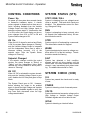
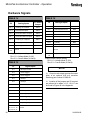
The following table (7) shows the passwords
required to change the Configuration parameters.
TABLE 7
Door
This parameter controls whether the MicroPak
2e Controller will use the state of the Door
hardware input in its control calculations.
Parameter
Password Level
Booth Air
System
Minimum Bearing Air
Broadcast Suppress System
This parameter sets the air pressure which
must be present at the Bearing Air Feedback
input before the turbine is allowed to operate.
Cascade Type
Config
Charge Type
Config
ComTimeOut
System
Config Password
Config
Date
User
DHCP
System
Door
System
EtherNet/IP Enable
User
FB Fault Delay
System
System Password
Feedback Fault
System
This parameter is the value entered for the
system password.
Interlock/Trigger
System
IP Address
System
MiscIO
System
Mode
Config
Storm Level
System
System Password
System
The charge type can be set to either DIRECT
or INDIRECT type. This setting must match
the type of charging provided by the applicator
being used as it controls the calculations of
the KV actual value.
Time
User
uPak VI Limiting
Config
User Password
User
Note the INDIRECT type can only be selected
when an RP1000 cascade is configured. All
other cascades will force Charge Type to be
configured as DIRECT.
Analog Inputs
System
Atomizer Type
Config
Min Bearing Air
System
Num Atomizers
System
NOTE
This input requires that bearing air be
monitored with a transducer which scales
0-100 psi to 0-10V or 0-100 psi to 4-20mA.
Password
This parameter is the value entered for the
user password.
Mode
The operating mode can be set to either
Voltage or Current mode. The mode selection
determines which independent setpoint (i.e.
kVSet or μASet) is the basis for control.
Charge Type
LN-9624-00
31
MicroPak 2e HV Controller - Operation
CONTROL CONDITIONS
SYSTEM STATUS (STS)
Power Up
STRT / RISE / FALL
On power up, the system does several checks
to determine hardware status. It checks
various signals to determine that there are no
faults, including feedback from the Variable
Voltage Output and High Voltage Inputs to
determine system status. If it determines that
it is OK to start, the Check display on the run
menu changes from VOL or INT to OK and
System Status changes to OK.
System is changing from one voltage/current
value to another. Di/dt and dv/dt checks are
disabled. The abbreviations stand for Starting. Rising and Falling.
HV On
STPD
When the HV On signal is received and Check
is OK, the system status changes to "Starting"
and the Variable Voltage Output is increased
until the Independent Value rises to within a
tolerance window (currently +/-3) of the
setpoint value. Then the System Status
changes to "Running".
System output is off and awaiting a command.
The abbreviation stands for Stopped.
Setpoint Changed
FALT
If the setpoint changes outside the control
window, the status changes to "Rising" or
"Falling" until the Independent Value again
reaches the control window at which point it
returns to "Running".
System has detected a fault condition,
stopped and will not allow starting until the
fault is reset. If the fault condition has not been
cleared, it may immediately fault without starting. The abbreviation stands for Fault.
HV Off
When HV Off is activated the system immediately sets the Variable Voltage Output to zero
volts, disables the HV Relay and goes to Stop
Mode.
The System Check goes to OK. However,
before allowing the output to be enabled
again, it checks the High Voltage and Variable
Voltage Output feedback signals to verify that
they have both decreased since the high
voltage was disabled.
RUN
System is attempting to keep a steady value
on Setpoint (the Independent Value). All enabled checks are active.
WARN
System has detected a current or voltage condition within 10% of the limit settings. The abbreviation stands for Warning.
SYSTEM CHECK (CHK)
OK
System has passed the checks and is ready
to start.
POWER
System is detecting a lack of cascade power.
VOLTG
System has detected excessive voltage on the
High Voltage or Variable Voltage Output
Feedback signals and will not allow a start.
INTLK
System is detecting an interlock failure.
32
LN-9624-00
MicroPak 2e HV Controller - Operation
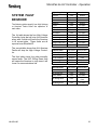
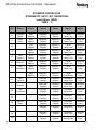
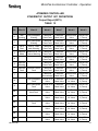
SYSTEM FAULT
BEHAVIOR
The following tables specify how High Voltage
or Atomizer Faults effect the operation of
each other.
The 1st table shows the four High Voltage
Controller faults that will stop the Atomizer
along with 8 which will leave the Atomizer
in its current state. These faults are all
reported over EtherNet/IP.
The second table shows that ALL Atomizer
Faults will stop the High Voltage Controller.
The third table shows four other miscellaneous faults. The HVC WDog Reset fault
will cause the Atomizer to stop since it will
loose it’s communications link.
LN-9624-00
High Voltage Faults
Interlock
Comm Time Out
Communications
Hardware
KV Low
DIDT or DVDT
HV Feedback
Min Output
Max KV
Over Voltage
Over Current
Voltage Cable Fault
Current Cable Fault
HV Action
Fault
Fault
Fault
Fault
Fault
Fault
Fault
Fault
Fault
Fault
Fault
Fault
Fault
Atom Action
Disable
Disable
Disable
Disable
No effect
No effect
No effect
No effect
No effect
No effect
No effect
No effect
No effect
Atomizer Faults
Bell Overspeed
Bell Underspeed
Loss Of Feedback
Low Bearing Air
Comm. Lost
HV Action
Disable
Disable
Disable
Disable
Disable
Atom Action
Fault
Fault
Fault
Fault
Fault
Other HV Faults
Remote Stop
HVC Power OFF
System Mode
HV Action
Fault
Fault
Fault
HVC WDog Reset
Fault
DSP WDog Reset
Fault
Atom Action
Disable
Disable
No effect
*RansNet Lost
Fault
No effect
33
MicroPak 2e HV Controller - Operation
NOTES
34
LN-9624-00
MicroPak 2e HV Controller - Operation
ETHERNET/IP
INTERFACE
The EtherNet/IP Interface for the MicroPak 2e
Controller is defined as a set of four 16 bit
words of input plus a set of four 16 bit words of
output. The Assembly instances are defined as
objects 100 (0x64) and 116 (0x74), where
object 100 is the input assembly and object 116
is the output assembly.
These bits are currently undefined and
unused.
Input Word 1
Bits (0-7) - kV Setpoint
This byte (8 bit) value determines the
active Voltage setpoint in kV.
Bits (8-15) - μA Setpoint
This byte (8 bit) value determines the
active Current setpoint in μA.
The Input bit definitions are shown in Table 8
and the Output bit definitions are shown in
Table 9 on the following pages.
NOTE
When defining the IO Instances to the
host system, specify the input object of the
controller as the output object of the host
and the output object of the controller as the
input object of the host.
NOTE
When an RP1000 or LEPS5002 cascade is selected, this value is multiplied by 5
to set the actual μA setpoint.
Input Word 2
Bits (0-7) - Parameter Value
These bits are currently undefined and
unused.
Description of Interface Elements
Input Word 0
Bit 0 - Enable Control
When this bit is set (high) the system
will attempt to keep the actual at the
appropriate setpoint.
Bit 1 - Reset Faults
When this bit is changed from low to
high (cleared to set) the system will
clear any fault bits if any are set and will
set the communication fault if no fault
bits are set.
Bit 2 - Current Mode
When this bit is set, the system will
operate in the Current Control Mode
and when cleared will operate in the
Voltage Control Mode.
Bits (3-15) - Unused
LN-9624-00
Bit (8-14) - Parameter Select Code
This 7 bit value determines
parameter to change.
the
Bit 15 - Parameter Write Strobe
When this bit changes from cleared to
set, the parameter value is written into
the selected parameter and displayed in
the Output Word 2.
Input Word 3
Bits (0-7) - Unused
These bits are currently undefined and
unused.
Bits (8-14) - Parameter Select code
The 7 bit value determines
parameter to change.
the
Bit 15 - Parameter Read Strobe
When this bit changes from cleared, to
set the Current Parameter Value is read
from the selected parameter and
displayed in the Output Word 3.
35
MicroPak 2e HV Controller - Operation
MicroPak 2e
ETHERNET/IP INPUT BIT DEFINITIONS
Input Object (0X64)
TABLE 8
36
Bit
Word 0
Word 1
Word 2
Word 3
0
HV Enable Control
kV Setpoint
Parameter
Value
1
Reset Faults
kV Setpoint
Parameter
Value
2
Current Mode
kV Setpoint
Parameter
Value
3
kV Setpoint
Parameter
Value
4
kV Setpoint
Parameter
Value
5
kV Setpoint
Parameter
Value
6
kV Setpoint
Parameter
Value
7
kV Setpoint
Parameter
Value
8
μA Setpoint
Parameter
Select Code
Parameter
Select Code
9
μA Setpoint
Parameter
Select Code
Parameter
Select Code
10
μA Setpoint
Parameter
Select Code
Parameter
Select Code
11
μA Setpoint
Parameter
Select Code
Parameter
Select Code
12
μA Setpoint
Parameter
Select Code
Parameter
Select Code
13
μA Setpoint
Parameter
Select Code
Parameter
Select Code
14
μA Setpoint
Parameter
Select Code
Parameter
Select Code
15
μA Setpoint
Parameter
Write Strobe
Parameter
Read Strobe
LN-9624-00
MicroPak 2e HV Controller - Operation
MicroPak 2e
ETHERNET/IP OUTPUT BIT DEFINITIONS
Output Object (0X74)
TABLE 9
Bit
Word 0
Word 1
Word 2
Word 3
0
In Control
Over Current Warning
Parameter
Data Value
Actual kV Value
1
Ramping
Over Voltage Warning
Parameter
Data Value
Actual kV Value
2
OK to Start
Under Voltage Warning
Parameter
Data Value
Actual kV Value
3
Remote Mode
Max Output Warning
Parameter
Data Value
Actual kV Value
4
HV On Echo
Communications Time
Out Fault
Parameter
Data Value
Actual kV Value
5
Warning
Interlock Fault
Parameter
Data Value
Actual kV Value
6
Fault
Communications Fault
Parameter
Data Value
Actual kV Value
7
Hardware Fault
Parameter
Data Value
Actual kV Value
8
Low Voltage Fault
Parameter
Select Code
Actual μA Value
9
dv/dt Fault
Parameter
Select Code
Actual μA Value
10
di/dt Fault
Parameter
Select Code
Actual μA Value
11
Minimum Output Fault
Parameter
Select Code
Actual μA Value
12
Feedback Fault
Parameter
Select Code
Actual μA Value
13
Over Voltage Fault
Parameter
Select Code
Actual μA Value
14
Over Current Fault
Parameter
Select Code
Actual μA Value
Cable Fault
Parameter
Acknowledge
Actual μA Value
15
LN-9624-00
Heartbeat
37
MicroPak 2e HV Controller - Operation
Output Word 0
Output Word 1
Bit 0 - In Control
Bit 0 - Over Current Warning
This bit is set when control is enabled
and the controlled value has reached
within three of the setpoint. This does
not mean that the value is still within
three of the setpoint, but that it had
been at one time.
Bit 1 - Ramping
This bit is set when the setpoint has
been changed and the controlled value
has not yet come within three of the
setpoint value.
During the time this bit is set, the di/dt
and dv/dt checks are not active.
Bit 2 - OK to Start
This bit is set when the system determines that the voltage values are in a
range where it is allowed to start control.
Bit 3 - Remote Mode
This bit is set when the front panel
switch is set to remote. When set, an
external unit can control the system.
Bit 4 - HV On Echo
This bit is set whenever HV is ON
Bit 5 - Warning
This bit is set whenever any warning is
in effect.
Bit 6 - Fault
This bit is set whenever any fault is in
effect (see "Fault Descriptions" in
"Troubleshooting
Guide"
in
the
"Maintenance" section).
Bits (7-14) - Unused
These bits are currently undefined and
unused.
Bit 15 - Heartbeat
This bit changes state every 1/4 second
producing two pulses per second.
38
The current value is within 10% of the
upper limit.
Bit 1 - Over Voltage Warning
The voltage value is within 10% of the
upper limit in current mode.
Bit 2 - Under Voltage Warning
The voltage value is within 10% of the
lower limit in current mode.
Bit 3 - Max Output Warning
The control voltage has reached its
maximum value.
Bit 4 - Communication Time Out Fault
The system has detected a communication loss which was greater than the
value specified by ComTimeOut.
Bit 5 - Interlock Fault
The system has detected one of the
active interlock input in an open state.
Bit 6 - Communication Fault
The system has detected a communication failure after an EtherNet/IP
connection was initiated.
Bit 7 - Hardware Fault
The system has detected a fatal System Failure.
Bit 8 - Low Voltage Fault
The system has fallen below the kV
Limit Lo while in Current Mode.
Bit 9 - dv/dt Fault
The system has detected a dv/dt event.
Bit 10 - di/dt Fault
The system has detected a di/dt event.
Bit 11 - Minimum Output Fault
The system has lowered the Variable
Voltage Output to zero and still is
above the setpoint.
LN-9624-00
MicroPak 2e HV Controller - Operation
Bit 12 - Feedback Fault
The system has measured an high
level of voltage or current feedback .which does not correspond to the
level of the control outputs being applied.
Bit 13 - Over Voltage Fault
The system has exceeded the kV Limit
Hi or the Max System Limit.
Bit 14 - Over Current Fault
The current value has exceeded the
Current (I) Limit Hi or the Max SystemLimit.
Bit 15 - Cable Fault
This bit is set whenever the voltage or
current feedback from the cascade has
been lost or fallen below the acceptable
value.
Output Word 2
Bits (0-7) - Parameter Data Value
This byte (8 bit) tells the system the
active parameter value.
NOTE
When an RP1000 or LEPS5002 cascade is selected, the μA value returned is
the actual value divided by 5.
Parameter Select Codes
Parameter Select = 1:
DvDt
READ—returns value of DvDT threshold
WRITE —sets value of DvDT threshold
Parameter Select = 2:
DiDt
READ—returns value of DiDT threshold
WRITE —sets value of DiDT threshold
Parameter Select = 3:
kVHi
READ—returns value of max KV allowed
WRITE —sets value of max KV allowed
Parameter Select = 4:
iHi
READ—returns value of max I allowed
WRITE —sets value of max I allowed
NOTE
Bits (8-14) - Parameter Select Code
This 7 bit value tells the system which
parameter is being displayed.
Bit 15 - Parameter Acknowledge
When this bit changes from cleared to
set a new Parameter Value is being
displayed. It is cleared when the Parameter Read Strobe and Parameter
Write Strobe are both cleared.
Output Word 3
Bits (0-7) - Actual kV Value
The byte (8 bit) value displays the latest
voltage reading in kV.
Bits (8-15) - Actual μA Value
This byte (8 bit) value displays the
latest current reading in μA.
LN-9624-00
When an RP1000 or LEPS5002 cascade is selected, the μA value passed is
scaled by 5 from the actual value.
Parameter Select = 5:
kVLo
READ—returns value of kVLo
WRITE —sets value of kVLo
Parameter Select = 6:
DxDtEna
READ—returns value of DxDtEna
WRITE —sets value of DxDtEna
NOTE
DxDtEna will enable the DxDt check
available in the control mode currently active. I.e. DiDT when in Voltage Mode and
DvDT when in Current Mode.
39
MicroPak 2e HV Controller - Operation
Parameter Select = 7:
Password 1
NOTES
READ—returns User password (X…)
WRITE —(Unsupported)
Parameter Select = 8:
Password 2
READ—returns User password (.X..)
WRITE —(Unsupported)
Parameter Select = 9:
Password 3
READ—returns User password (..X.)
WRITE —(Unsupported)
Parameter Select = 10:
Password 4
READ—returns User password (...X)
WRITE —(Unsupported)
TABLE 10
Parameter
Min Value
Max Value
DvDT
0
60
DiDt
0
60
kVHi
20
100
iHi
10
Per Cascade
kVLo
0
80
DxDtEna
0 = Disable
1 = Enable
Password 1
0
9
Password 2
0
9
Password 3
0
9
Password 4
0
9
NOTE
The per Cascade iHi values can be
found in the Electrical Specifications located
in the Introduction section.
40
LN-9624-00
MicroPak 2e HV Controller - Operation
NOTES
LN-9624-00
41
MicroPak 2e Atomizer Controller - Introduction
INTRODUCTION—ATOMIZER CONTROLLER
ATOMIZER CONTROLLER
GENERAL DESCRIPTION
The Atomizer Controller for use with the
MicroPak 2e Controller is designed to
continuously monitor and maintain the
programmable speed of a rotary atomizer as
well as provide a universal I/O interface for
many atomizer functions. This module utilizes
closed-loop control via a fiber optic cable to
maintain the rotator speed. A number of
configuration options are available to the end
user. These include built in support for many
Ransburg rotary atomizers as well as an
assortment of inputs and outputs available to
the user.
Electrical Requirements
Power Required:
J15 - Controller : 24V DC
@ 0.25 Amps
Note: 24V DC power supply must be regulated and have over current and over voltage protection.
Electrical
Communication Requirements
Control and Reporting:
Ethernet to the MicroPak 2e:
port J8 or J9
Note: A unique MAC address is hard coded
into each Atomizer Controller.
Electrical
Controls in Local Mode
NOTE
Signals shown in bold below are minimum required functions for Atomizer
control to operate.
Figure 41: MicroPak 2e Multi I/O Board
SPECIFICATIONS
(At Sea-Level Conditions)
Environmental / Physical
Operating Temperature:
Storage and Shipping
Temperature:
Humidity:
Physical Size:
Mounting:
42
0°C to +55°C
-40°C to +85°C
95% Non-Condensing
2" tall X 7.5" X 4.75"
Figure 44 in Appendix
Analog In:
BEARING
(0-10V or 4-20mA)
AIR FEEDBACK
Analog Out:
(0-10V or 4-20mA)
BELL DRIVE
Bell Speed Read Out
Discrete In:
(Dry Contact)
(None active)
Discrete Out: (Dry Contact)
BRAKE
Overspeed Warn/Fault
Underspeed Warn/Fault
Loss of Bell Feedback Warn/Fault
Low Bearing Air Warn/Fault
Speed Out of Tolerance Warn
LN-9624-00
MicroPak 2e Atomizer Controller - Introduction
Electrical
Electrical
Controls in Remote EtherNet/IP Mode
Controls in Remote Discrete Mode
Analog In:
BEARING
(0-10V or 4-20mA)
AIR FEEDBACK
Analog Out:
(0-10V or 4-20mA)
BELL DRIVE
Bell Speed Read Out
Discrete In:
(Dry Contact)
(None active)
Discrete Out:
(Hi-Side Switch)
BRAKE
Paint Trigger #1
Paint Trigger #2
Dump #1
Dump #2
Fluid Override #1
Fluid Override #2
Cup Wash
Overspeed Warn/Fault
Underspeed Warn/Fault
Loss of Bell Feedback Warn/Fault
Low Bearing Air Warn/Fault
Speed Out of Tolerance Warn
Analog In: (0-10V or 4-20mA)
BEARING AIR FEEDBACK
Bell Speed Setpoint
Flowrate Setpoint #1
Flowrate Setpoint #2
Shaping Air Setpoint #1
Shaping Air Setpoint #2
Analog Out: (0-10V or 4-20mA)
BELL DRIVE
Bell Speed Read Out
Flowrate #1
Flowrate #2
Shaping Air #1
Shaping Air #2
Discrete In:
(Dry Contact)
BELL SPIN ENABLE
Paint Trigger #1
Paint Trigger #2
Dump #1
Dump #2
Fluid Override #1
Fluid Override #2
Cup Wash
Discrete Out:
(Dry Contact)
BRAKE
Paint Trigger #1
Paint Trigger #2
Dump #1
Dump #2
Fluid Override #1
Fluid Override #2
Cup Wash
Overspeed Warn/Fault
Underspeed Warn/Fault
Loss of Bell Feedback Warn/Fault
Low Bearing Air Warn/Fault
Speed Out of Tolerance Warn
LN-9624-00
43
MicroPak 2e Atomizer Controller - Introduction
SPEED CONTROL
The Atomizer Controller is used in a closedloop rotational speed control system for rotary
atomizers as shown in Figure 42. It accepts a
requested speed command and, after
comparing this with the actual speed feedback
from the atomizer, provides an output to
maintain the requested speed.
When a speed request is received, the
controller activates the Turbine Drive signal
which controls the output of an E to P
transducer providing an air pilot signal to a 1:1
volume booster. The volume booster supplies
high volume drive air to the rotary atomizer.
The atomizer speed is monitored by a fiber
optic cable to a fiber optic transceiver mounted
on the Atomizer Controller board.
The
transceiver provides a speed feedback signal
to the Atomizer Controller which is timed to
determine the rotational speed. The speed, in
increments of 1000's rpm, is displayed on the
MicroPak 2e Controller front panel.
An optional braking system provides for rapid
slowdown. When changing speeds from high
to low (change greater than 3,000 rpm), the
controller provides an electrical brake signal to
drive a pneumatic solenoid which delivers high
pressure air to the brake input of the atomizer.
Ransburg part numbers, for each of the components described, are listed in the MicroPak
2e High Voltage Controller Parts List located
in this manual.
NOTE
A speed command of 1 krpm is
recognized by the controller as an
emergency stop condition and will cause the
brake to stay engaged until the speed
reaches 2 krpm from which the turbine will
coast to a stop.
A speed command of 0 krpm does not
actuate the brake but allows the turbine to
coast to a stop condition.
Figure 42: MicroPak 2e Controller/Atomizer Minimal System
44
LN-9624-00
MicroPak 2e Atomizer Controller - Introduction
NOTES
The speed feedback signal is designed to
drop out at about 2 krpm and the controller will
set a Loss of Feedback Fault. A new speed
command will reset the fault at the Atomizer
Controller, but the MicroPak 2e Controller will
only reset its fault indication when
commanded by the EtherNet/IP interface or
the front panel HV On/Off switch.
An electrical input is provided and required for
atomizer bearing air sensing and interlock.
Minimum bearing air pressure threshold is set
at 80 psi. This can be changed as described
in the section titled MicroPak 2e Controller
Configuration.
The maximum allowed speeds for various
rotator types is shown in the "Specifications"
in the "Introduction" section. There are no
minimum speed limits set by the Atomizer
Controller itself, however, the low speed
operation is limited by the drop out of speed
feedback signal at about 2 krpm.
LN-9624-00
45
MicroPak 2e Atomizer Controller - Operation
OPERATION—ATOMIZER CONTROLLER
OPERATION
AUTOMATIC SHUTDOWN
The Atomizer Controller currently supports
three different operating modes with varying
levels of capabilities.
The
Atomizer Controller continuously
monitors turbine operation and detects
common fault conditions and will automatically
stop the atomizer when one is detected.
Remote EtherNet/IP Control
This mode gives the remote system full
access to the atomizer parameters and allows
control of starting and stopping as well as
collection of fault information.
Remote Discrete Control
This mode is only available when EtherNet/IP
is disabled. While it provides no access to the
atomizer parameters, it does allow the remote
system to control starting, stopping and various other functions provided through the Atomizer Controller inputs and outputs. See tables 14, 15, 16, &17 for a complete list of I/O
functions.
Local Front Panel Control
This mode is available whenever the MicroPak
2e Controller is in Local mode. In the current
software release, operation is limited to starting and stopping the atomizer by means of the
Atomizer On/Off switch located on the front
panel.
NOTE
In local mode the Turbine Speed Set point
can be set from the front panel and that
value will be used for local operation. Upon
exiting Local mode, control of the Turbine
Speed Setpoint reverts to either the
EtherNet/IP interface or the Discrete inputs.
1. Overspeed: If the speed feedback exceeds the speed setpoint.
Liquid Bell - 10,000 rpm above setpoint
Disk - any speed over 30 krpm
Time delay is 0.5 seconds
2. Underspeed: If the speed feedback is less
than the speed setpoint:.
Liquid Bell - 10,000 rpm under setpoint
Disk - No underspeed checks made
Time delay is 0.5 seconds.
3. Loss of Feedback: Senses when feedback should be present but is not.
Pulses received from the fiber optics
must be no greater than 800 msec apart
during normal operation.
Start-up delay:
Liquid Bell - 1 second for the first pulse
Disk - 7 seconds
Once the first pulse has been received, the
800 msec interval applies.
4. Invalid Speed Command: Will not process speed requests higher than rated maximum. Internally set speed command to zero.
5. Low Bearing Air Pressure: If the bearing air pressure feedback drops below the
minimum bearing air threshold. There is a 4
second time delay for all settings.
6. Interlock Open: If an active interlock is
opened while the atomizer is running, all
outputs will be disabled and a brake assisted ESTOP will be done before faulting.
46
LN-9624-00
MicroPak 2e Atomizer Controller - Operation
Out of Tolerance (WARNING)
Speed is not within +/- 5% of setpoint, no
internal action taken, 1 second delay.
Signal may be used externally as desired.
INTERFACING
CONSIDERATIONS
When using an Atomizer there are some operational restrictions that must be observed to
avoid damaging the turbine. Five of these
conditions were listed in the Automatic Shutdown section and are automatically enforced
by the Atomizer Controller. There is also a
sixth condition which the controller is programed to prevent. That is, the flow of paint to
the bell when the Atomizer is not spinning.
This operational interlock is accomplished by
deactivating the signals Paint Trigger #1 and
Paint Trigger #2 whenever the Atomizer is not
running, i.e. either IDLE or FAULTED.
!
CAUTION
If the user chooses not to use the discrete outputs Paint Trigger #1 and Paint
Trigger #2 provided by the Atomizer Controller, then they are responsible for implementing a comparable interlock between
Atomizer operation and paint flow. Failure
to do so may result in a turbine failure.
LN-9624-00
ETHERNET/IP INTERFACE
The EtherNet/IP Interface for the Atomizer
Controller is defined as two assembly instances that contain the MicroPak 2e interface in
the first four words of the input and output
sets. Six additional words for the Atomizer
Controller have been added at the end of the
MicroPak 2e EtherNet/IP interface.
This means that the Atomizer Controller interface is a set of ten 16 bit words of input plus a
set of ten 16 bit words of output. The Assembly instances are defined as objects 101
(0x65) and 117 (0x75), where object 101 is
the input assembly and object 117 is the output assembly.
Since the first four words of the Atomizer Controller interface are identical to those defined
for the MicroPak 2, the following interface description only includes the six words which are
specific to the Atomizer Controller. The Input
bit definitions are shown in Table 11 and the
Output bit definitions are shown in Table 12 on
the following pages.
47
MicroPak 2e Atomizer Controller - Operation
ATOMIZER CONTROLLER
ETHERNET/IP INPUT BIT DEFINITIONS
Input Object (0X65)
TABLE 11
Bit
Word 4
Word 5
Word 6
Word 7
Word 8
Word 9
0
Atomizer
Enable
RPM
Setpoint
ShapeAir 1
Setpoint
ShapeAir 2
Setpoint
Param
Read Code
Parameter
Value
1
Reset
Faults
RPM
Setpoint
ShapeAir 1
Setpoint
ShapeAir 2
Setpoint
Param
Read Code
Parameter
Value
2
RPM
Setpoint
ShapeAir 1
Setpoint
ShapeAir 2
Setpoint
Param
Read Code
Parameter
Value
3
RPM
Setpoint
ShapeAir 1
Setpoint
ShapeAir 2
Setpoint
Param
Read Code
Parameter
Value
4
Paint
Trigger #1
RPM
Setpoint
ShapeAir 1
Setpoint
ShapeAir 2
Setpoint
Param
Read Code
Parameter
Value
5
Dump #1
RPM
Setpoint
ShapeAir 1
Setpoint
ShapeAir 2
Setpoint
Param
Read Code
Parameter
Value
6
Fluid
Override #1
RPM
Setpoint
ShapeAir 1
Setpoint
ShapeAir 2
Setpoint
Param
Read Code
Parameter
Value
RPM
Setpoint
ShapeAir 1
Setpoint
ShapeAir 2
Setpoint
Param
Read Strobe
Parameter
Value
7
8
Paint
Trigger #2
FlowRate 1
Setpoint
FlowRate 2
Setpoint
Parameter
Write Code
Parameter
Value
9
Dump #2
FlowRate 1
Setpoint
FlowRate 2
Setpoint
Parameter
Write Code
Parameter
Value
10
Fluid
Override #2
FlowRate 1
Setpoint
FlowRate 2
Setpoint
Parameter
Write Code
Parameter
Value
FlowRate 1
Setpoint
FlowRate 2
Setpoint
Parameter
Write Code
Parameter
Value
FlowRate 1
Setpoint
FlowRate 2
Setpoint
Parameter
Write Code
Parameter
Value
13
FlowRate 1
Setpoint
FlowRate 2
Setpoint
Parameter
Write Code
Parameter
Value
14
FlowRate 1
Setpoint
FlowRate 2
Setpoint
Parameter
Write Code
Parameter
Value
15
FlowRate 1
Setpoint
FlowRate 2
Setpoint
Parameter
Write Strobe
Parameter
Value
11
12
48
Bell Cup
Wash
LN-9624-00
MicroPak 2e Atomizer Controller - Operation
Input Word 4
Bit 0 - Atomizer Enable
When this bit is set (high) the system
will attempt to keep the actual at the
appropriate setpoint.
Bit 1 - Reset Atomizer Faults
When this bit is changed from low to
high (cleared to set) the system will
clear any fault bits if any are set and
will set the communication fault if no
fault bits are set.
Bits (2-3) - Unused
These bits are currently unused.
Bit 4 - Paint Trigger #1
When this bit is set, the system will activate the Paint Trigger #1 output and
when cleared will de-activate the Paint
Trigger #1 output. This output is only
active when the bell is running.
Bit 5 - Dump #1
When this bit is set, the system will activate the Dump #1 output and when
cleared will de-activate the Dump #1
output.
Bit 6 - Fluid Override #1
When this bit is set, the system will activate the Fluid Override #1 output and
when cleared will de-activate the Fluid
Override #1 output.
Bit 7 - Unused
This bit is currently unused.
Bit 8 - Paint Trigger #2
When this bit is set, the system will activate the Paint Trigger #2 output and
when cleared will de-activate the Paint
Trigger #2 output. This output is only
active when the bell is running.
output.
Bit 10 - Fluid Override #2
When this bit is set, the system will activate the Fluid Override #2 output and
when cleared will de-activate the Fluid
Override #2 output.
Bit 11 - Unused
This bit is currently unused.
Bit 12 - Bell Cup Wash
When this bit is set, the system will activate the Bell Cup Wash output and
when cleared will de-activate the Bell
Cup Wash output.
Input Word 5
Bits (0-7) - kV Setpoint
This byte (8 bit) value determines the active Voltage setpoint in kV.
Bits (8-15) - Unused
These bits are currently unused.
Input Word 6
Bits (0-7) - Shape Air 1 Setpoint
This byte (8 bit) value determines the
Shaping Air 1 setpoint in % of full scale.
Bits (8-15) - Flow Rate 1 Setpoint
This byte (8 bit) value determines the
Flow Rate 1 setpoint in % of full scale.
Input Word 7
Bits (0-7) - Shape Air 2 Setpoint
This byte (8 bit) value determines the
Shaping Air 2 setpoint in % of full scale.
Bits (8-15) - Flow Rate 2 Setpoint
This byte (8 bit) value determines the
Flow Rate 2 setpoint in % of full scale.
Bit 9 - Dump #2
When this bit is set, the system will activate the Dump #2 output and when
cleared will de-activate the Dump #2
LN-9624-00
49
MicroPak 2e Atomizer Controller - Operation
Input Word 8
NOTES
Bits (0-6) - Parameter Read Code
This 6 bit value determines the parameter to read.
Bit 7 - Parameter Read Strobe
When this bit changes from cleared to
set, the parameter value is read from
the selected parameter and displayed
in Output Word 7.
Bits (8-14) - Parameter Write Code
This 6 bit value determines the parameter to set.
Bit 15 - Parameter Write Strobe
When this bit changes from cleared to
set, the parameter value is written into
the selected parameter and displayed
in Output Word 7.
Input Word 9
Bits (0-15) - Parameter Value
This 16 bit value is written to the parameter being changed.
50
LN-9624-00
MicroPak 2e Atomizer Controller - Operation
ATOMIZER CONTROLLER
ETHERNET/IP OUTPUT BIT DEFINITIONS
Output Object (0X75)
TABLE 12
Bit
Word 4
Word 5
Word 6
Word 7
Word 8
Word 9
0
Bell
Running
Bell Overspeed
Warning
Parameter
Read Code
Parameter
Read Value
Actual RPM
Value
Actual Flow
1 (Future)
Bell Underspeed
Warning
Parameter
Read Code
Parameter
Read Value
Actual RPM
Value
Actual Flow
1 (Future)
1
2
OK to
Start
Loss of Feedback Warning
Parameter
Read Code
Parameter
Read Value
Actual RPM
Value
Actual Flow
1 (Future)
3
Remote
Mode
Speed Out of Tolerance Warning
Parameter
Read Code
Parameter
Read Value
Actual RPM
Value
Actual Flow
1 (Future)
Parameter
Read Code
Parameter
Read Value
Actual RPM
Value
Actual Flow
1 (Future)
Parameter
Read Code
Parameter
Read Value
Actual RPM
Value
Actual Flow
1 (Future)
Parameter
Read Code
Parameter
Read Value
Actual RPM
Value
Actual Flow
1 (Future)
Parameter
Acknowledge
Parameter
Read Value
Actual RPM
Value
Actual Flow
1 (Future)
4
5
Atomizer
Warning
6
Atomizer
Fault
Atomizer Comm
Fault
7
8
Bell Overspeed
Fault
Turbine Drive
Value
Parameter
Read Value
Actual Bearing Actual Flow
Air Value
2 (Future)
9
Bell Underspeed
Fault
Turbine Drive
Value
Parameter
Read Value
Actual Bearing Actual Flow
Air Value
2 (Future)
10
Loss of Feedback Fault
Turbine Drive
Value
Parameter
Read Value
Actual Bearing Actual Flow
Air Value
2 (Future)
Turbine Drive
Value
Parameter
Read Value
Actual Bearing Actual Flow
Air Value
2 (Future)
Turbine Drive
Value
Parameter
Read Value
Actual Bearing Actual Flow
Air Value
2 (Future)
13
Turbine Drive
Value
Parameter
Read Value
Actual Bearing Actual Flow
Air Value
2 (Future)
14
Turbine Drive
Value
Parameter
Read Value
Actual Bearing Actual Flow
Air Value
2 (Future)
15
Turbine Drive
Value
Parameter
Read Value
Actual Bearing Actual Flow
Air Value
2 (Future)
11
12
LN-9624-00
Low Bearing Air
Fault
51
MicroPak 2e Atomizer Controller - Operation
Output Word 4
Bit 0 - Bell Running
This bit is set when the atomizer control
is enabled. It means that the atomizer
controller is actively attempting to
control the bell speed.
Bit 1 - Unused
Bit 2 - OK to Start
This bit is set when the system determines that the voltage values are in a
range where it is allowed to start control.
Bit 3 - Remote Mode
This bit is set when the front panel
switch is set to remote. When set, an
external unit can control the system.
This bit is set when the Atomizer
detects a loss of feedback condition as
described in the “Automatic Shutdown”
section.
Bit 3 - Speed Out of Tolerance Warning
This bit is set when the Atomizer
detects a speed out of tolerance
condition as described in the
“Automatic Shutdown” section.
Bits (4-5) - Unused
These bits are currently undefined and
unused.
Bit 6 - Atomizer Communication Fault
The system has detected a communication failure after an EtherNet/IP
connection was initiated.
Bit 4 - Unused
Bit 7 - Unused
Bit 5 - Warning
Bit 8 - Bell Overspeed Fault
This bit is set whenever an Atomizer
warning is in effect.
Bit 6 - Fault
This bit is set whenever an Atomizer
fault is in effect (see "Fault Descriptions" in "Troubleshooting Guide" in the
"Maintenance" section).
Bits (7-15) - Unused
These bits are currently undefined and
unused.
Output Word 5
Bit 0 - Bell Overspeed Warning
This bit is set when the Atomizer
detects an overspeed condition as
described in the “Automatic Shutdown”
section.
Bit 1 - Bell Underspeed Warning
This bit is set when the Atomizer
detects an underspeed condition as
described in the “Automatic Shutdown”
section.
52
Bit 2 - Loss of Feedback Warning
This bit is set when the Atomizer
faults due to an overspeed condition
as described in the “Automatic Shutdown” section.
Bit 9 - Bell Underspeed Fault
This bit is set when the Atomizer
faults due to an underspeed condition
as described in the “Automatic Shutdown” section.
Bit 10 - Loss of Feedback Fault
This bit is set when the Atomizer
faults due to a loss of feedback condition as described in the “Automatic
Shutdown” section.
Bit 11 - Unused
Bit 12 - Low Bearing Air Fault
This bit is set when the Atomizer
faults due to a low bearing air pressure condition as described in the
“Automatic Shutdown” section.
Bits (13-15) - Unused
LN-9624-00
MicroPak 2e Atomizer Controller - Operation
Output Word 6
Parameter Select Codes
Bits (0-6) - Parameter Read Code
Parameter Select = 1:
This 7 bit value tells the system which
parameter is being displayed.
Bit 7 - Parameter Acknowledge
When this bit changes from cleared to
set a new Parameter Value is being
displayed. It is cleared when the Parameter Read Strobe and Parameter Write
Strobe are both cleared.
Bits (8-15) - Turbine Drive Value
This byte (8 bit) value displays the air
pressure applied to the Atomizer turbine. If this value is monitored for
each speed and paint combination, it
can be used as an indicator of correct
operation or a potential problem.
Output Word 7
Bits (0-15) - Parameter Read Value
This 16 bit value tells the system which
parameter is being displayed.
Output Word 8
Bits (0-7) - Actual RPM Value
The byte (8 bit) value displays the latest
turbine speed in 1000 RPM.
Bits (8-15) - Actual Bearing Air Value
This byte (8 bit) value displays the
latest bearing air pressure reading.
Output Word 9
Bits (0-7) - Actual Flow #1 Value
In the future this byte (8 bit) value will
be used to display the latest measurement of flow rate #1.
Bits (8-15) - Actual Flow #2 Value
In the future this byte (8 bit) value will
be used to display the latest measurement of flow rate #2.
LN-9624-00
Atom Enabled
READ—returns value 0=Disabled
1= Enabled
WRITE —is not supported
Parameter Select = 2:
Atom Type
READ—returns value 0=RMA300-500
1= AeroBelll
2= AeroBell33
3= RMA100-200
4= TurboDisk
5= Auto Gun
WRITE —is not supported.
Parameter Select = 3:
Input Mode
READ—returns bit values of 0-127
WRITE —sets bit values of 0-127
See Table 13 for bit details
See table for corresponding jumpers
Parameter Select = 4:
Min Bearing Air
READ—returns value 0—100
WRITE —sets value 0—100
TABLE 13
Bit
Analog Input
0
1) Bearing Air Feedback
1
2) Bell Speed Setpoint
2
3) Paint Flow Rate 1 Setpoint
3
4) Paint Flow Rate 2 Setpoint
4
5) Shaping Air 1 Setpoint
5
6) Shaping Air 2 Setpoint
7
7) (unassigned)
A “0” bit = Voltage Mode (0-10V)
A “1” bit = Current Mode (4-20mA)
53
MicroPak 2e Atomizer Controller - Operation
Hardware Signals
TABLE 14
TABLE 16
V-I Select
Jumper
J14
Analog Inputs
J14-1
1—Bearing Air Feedback
JMP15
J14-3
2—Bell Speed Setpoint
JMP14
J14-5
3—Paint Flow Rate 1 Setpoint
JMP13
J14-7
4—Paint Flow Rate 2 Setpoint
JMP12
J14-9
5—Shaping Air 1 Setpoint
J14-11
J14-13
even
pins
Analog Outputs
V-I Select
J4-1
1—Bell Drive
JMP1
J4-3
2—Bell Speed Read Out
JMP2
J4-5
3—Paint Flow Rate 1
JMP3
J4-7
4—Paint Flow Rate 2
JMP4
J4-9
5—Shaping Air 1
JMP5
JMP11
J4-11
6—Shaping Air 2
JMP5
6—Shaping Air 2 Setpoint
JMP10
J4-13
7—(future)
JMP7
7—(unassigned)
JMP9
J4-15
8—(future)
JMP8
Ground
Ground
Analog Input Jumper setting:
Pins 1-2 = Voltage Mode (0-10V)
Pins 2-3 = Current Mode (4-20mA)
TABLE 15
J5
Digital Inputs
J5-1
1—Bell Spin Enable
J5-3
2—Paint Trigger 1
J5-5
3—Paint Trigger 2
J5-7
4—Dump 1
J5-9
5—Dump 2
J5-11
6—Fluid Override 1
J5-13
7—Fluid Override 2
J5-15
8—Bell Cup Wash
J5-17
9—(unassigned)
J5-19
10—(unassigned)
J5-21
11—(unassigned)
J5-23
12—(unassigned)
J5-2, 4, 6, 8,
10, 12 , 14, 16,
18, 20, 22, 24
54
J4
J4-17, J418
(N.C.)
Analog Output Jumper setting:
Pins 1-2 = Voltage Mode (0-10V)
Pins 2-3 = Current Mode (4-20mA)
NOTE
Current mode output requires the installation of an optional 4-20 mA converter:
Ransburg part number A13248-00.
Location of the jumpers and I/O connectors referred to in tables 14, 15, 16 & 17 can
be found in Figure 45 in the Appendix.
Ground
LN-9624-00
MicroPak 2e Atomizer Controller - Operation
NOTES
TABLE 17
J1
Digital Outputs
J1-1
1—Brake
J1-3
2—Paint Trigger 1
J1-5
3—Paint Trigger 2
J1-7
4—Dump 1
J1-9
5—Dump 2
J1-11
6—Fluid Override 1
J1-13
7—Fluid Override 2
J1-15
8—Bell Cup Wash
J1-17
9—Overspeed Warning/Fault
J1-19
10—Underspeed Warning/Fault
J1-21
11—Loss of Bell Feed Back Warning/
Fault
J1-23
12—Low Bearing Air Warning/Fault
J1-25
13—Speed Out of Tolerance Warning
J1-27
14—(unassigned)
J1-29
15—(unassigned)
J1-31
16—(unassigned)
J1-33
17—(future)
J1-35
18—(unassigned)
J1-2, 4, 6, 8,
10, 12 , 14, 16,
18, 20, 22, 24,
26, 28, 30, 32,
34, 36
Ground
LN-9624-00
55
MicroPak 2e HV Controller - Integration Notes
INTEGRATION NOTES
GUIDELINES
Networking:
It is important to use a suitably configured network for EtherNet/IP communications. Following is a list of Ransburg’s recommendations:
Use a private switched LAN for an EtherNet/IP control network.
For large installations the use of a switch
which supports IGMP Snooping is recommended. These switches can direct multicast traffic to only the multicast group
members instead of broadcasting it to all
connected ports.
NOTE
The MicroPak 2e does not support multicast communications.
Many PLCs and robots make use of
multicast communications to minimize packet transmissions. Low cost Ethernet switches treat these as broadcasts and send these
messages to all connected devices. This
can present a substantial processing load for
devices which are not group members.
Do not allow Internet access from the
EtherNet/IP control network.
Monitor the EtherNet/IP control network to
confirm it remains isolated.
If remote monitoring from the plant LAN is
necessary, use a managed gateway to limit access to the private LAN.
For further guidance refer to ODVA document:
Network Infrastructure for EtherNet/IPTM, Publication Number: PUB00035R0.
56
EtherNet/IP TCP Configuration:
The present implementation of TCP Configuration through EtherNet/IP, requires that the
MicroPak 2e does not have another active
EtherNet/IP connection when the TCP Configuration message exchange occurs.
This
means that if a PC is being used to set the
TCP configuration, there must not be a PLC or
robot link to the MicroPak 2e (i.e. the Fault
Menu Screen must show “eip” in lower case).
It is planned to address this issue in a future
software update.
Atomizer Operation:
When deciding how to control an atomizer,
there are several important issues to consider.
1. The atomizer must not be run without an
adequate supply of bearing air.
2. The flow of paint must be interlocked with
the atomizer’s rotation. That is, paint must
not flow if the atomizer is not rotating.
Failure to stop the flow of paint will result
in “flooding” which can destroy an atomizer.
3. The flow of solvent must be interlocked
with the atomizer’s rotation and also with
the high voltage control.
Compliance with item 1 is built into the Atomizer Controller and requires user action to defeat. The user is responsible for the effects of
defeating this operational interlock.
Compliance with item 2 is easily achieved by
using the Paint Trigger outputs of the Atomizer Controller. The controller has been programmed to interlock these outputs with the
atomizer’s rotation, thereby freeing the user
from adding additional control logic to meet
this requirement. This behavior is included in
all input modes.
LN-9624-00
MicroPak 2e HV Controller - Integration Notes
Compliance with item 3 is also easily achieved
by using the Wash output (Bell Cup/Disk/Gun)
of the Atomizer Controller. The controller has
been programmed to interlock this output with
the high voltage controller, so that if high voltage controller is enabled, the Bell Cup Wash
output will not activate. This will prevent solvent from being dispensed when high voltage
is present.
!
CAUTION
Failure to interlock the flow of paint
with atomizer rotation may cause damage
to the atomizer.
Atomizer Interlock Behavior:
To help implement a safer paint booth, the
High Voltage controller has been programmed
to provide the state of the interlocks to the Atomizer controller with each update packet.
This enables the Atomizer Controller to perform a forced stop, using the air brake, if an
interlock opens while the atomizer is in motion. In addition, the atomizer controller will
also immediately disable the paint and solvent
outputs.
The bits contained in output words one and
five are provided to aid fault isolation. These
bits should not be relied on for fault detection,
since it is not guaranteed that a fault will always set an isolating bit.
Controller DIP Switch Settings:
Both the High Voltage Control Processor and
the Display and Communications Processor
boards have a 2 position dip switch labeled
S1. Switch 1 is not currently used and switch
2 which is for factory use only, should remain
in the CLOSED position for normal operation.
Likewise, the MicroPak 2e Multi I/O Board
(Atomizer Controller) contains a 6 position dip
switch labeled S1. The first four switch positions are used to determine the I/O function of
the Multi I/O Board. For the Atomizer board,
switches 1, 3 & 4 must be CLOSED and
switch 2 must be OPEN. Switch 5 is not currently used and switch 6, which is for factory
use only, should remain in the CLOSED position for normal operation.
Atomizer - MP2e Power Cycling
When the MP2e power is cycled quickly using
the front panel switch (i.e. OFF for less than 3
seconds), an Atomizer fault may occur. This
is because the Atomizer Controller executes a
reboot operation every time a failure of the
RansNet communications link is detected.
This behavior ensures the Atomizer Controller
always has current configuration data from the
MP2e.
Controller Fault Detection:
When programming the controlling PLC to detect faults the user should always:
Use bit 6 of output word zero to detect a
Voltage Controller fault.
Use bit 6 of output word four to detect an
Atomizer Controller fault.
LN-9624-00
57
MicroPak 2e HV Controller - Maintenance
MAINTENANCE
TROUBLESHOOTING GUIDE
!
WARNING
Before troubleshooting gun and control unit problems, flush the gun with solvent and
purge with air. Some of the tests will require high voltage to be applied to the gun, so the gun
must be empty of paint and solvent.
Fault
Description
Solution
Cable Fault (CF)
The Cable Fault indicates the
1. Check for loose wiring between the pc
control unit does not detect a
board connector and the high voltage
high voltage section on the end
section by pulling on each wire. Repair
of the cable. The fault typically
if necessary. Insure both connectors
occurs at a high voltage trigare secure and re-test for CF fault.
ger.
2. Replace high voltage section or send
unit in for repair.
3. Send unit in for repair.
FAULT/WARN TROUBLESHOOTING GUIDES
General
Problem
Atom Faults
Fault Report
No Fault
No Fault was detected.
Bell Overspeed
The bell speed feedback indicated the bell exceeded the setpoint. *
Bell Underspeed
The bell speed feedback indicated the bell was below the setpoint. *
Loss of Feedback
The fiber optic speed feedback signal was not detected. *
Low Bearing Air
The bearing air monitor indicated the pressure was too low. *
RansNet CommLost
The Ethernet communications between the HVC and speed controller
were interrupted.
Faulted by HVC
The speed controller has been stopped due to an HVC fault.
Interlock
The Atomizer controller has detected an open interlock. *
Atom Warns Speed Out of Tol
58
Explanation
Speed is not within +/- 5% of setpoint. *
For further information, see “Automatic Shutdown” in the section of this manual on
Operation of the Atomizer.
LN-9624-00
MicroPak 2e HV Controller - Maintenance
General
Problem
HVC Faults
Fault Report
Explanation
No Fault
No Fault was detected.
Over Current
The current value has exceeded the I Limit Hi or the Max System Limit.
MAX KV
The system has raised the Variable Voltage Output to the system maximum, but could not reach the setpoint.
Min Output
The system has lowered the Variable Voltage Output to zero and still is
above the setpoint.
kV Limit
The system has exceeded the kV Limit Hi or the Max System Limit.
DVDT
The system has detected a dv/dt event.
DIDT
The system has detected a di/dt event.
Cascade Feedback The current or voltage feedback from the cascade is out of range.
HVC
Warns
LN-9624-00
Voltage Cable
The system has detected a loss of the High Voltage Feedback signal
from a Consolidated cascade..
Current Cable
The system has detected a loss of the Current Feedback signal from a
Consolidated cascade...
KV Low
The system has fallen below kV Lo Limit while operating in Current
Mode.
Communications
The system has detected an EtherNet/IP communication failure. Possible causes are:
- Receipt of a reset command when no fault was active.
- Receipt of an invalid high voltage controller parameter value.
- Receipt of an invalid atomizer parameter value, Atomizer Fault LED
will also be lit
FLT’d by Atom
An atomizer fault has caused the high voltage controller to stop.
Comm Timeout
Either the MP2e or the “originating” EtherNet/IP controller failed to receive a message for three update intervals, so the connection was
dropped.
System Mode
The control software detected an invalid state.
Interlock
One of the enabled interlock input circuits was broken, i.e. the circuit
was opened..
Remote Stop
The Remote Stop input circuit was opened.
HVC WDog Reset
The high voltage control processor board reset by the WatchDog Timer.
DSP WDog Reset
The display processor board reset by the WatchDog Timer.
HV Power Off
External power was removed from the cascade power input—J4.
Over Current
The current level is within 10% of Max uA Limit.
Over Voltage
The voltage level is within 10% of KV High Limit (current mode only).
Under Voltage
The voltage level is within 10% of KV Low Limit (current mode only).
Max Output
Vct is maximum and the kV setpoint has not been reached.
KV High Limit
The voltage level (kV) is within 10% of kV Maximum, i.e. 110 kV.
59
MicroPak 2e HV Controller - Parts
MicroPak 2e High Voltage Controller - Parts List
Part #
Description
MicroPak 2e HV & Atomizer Controller
A13338-XX XX XX For replacement use, the user should order the same model number
(-XXXXXX) that was listed on the original invoice.
60
A13245-00
MicroPak 2e Multi-Function Board
A13248-00
MicroPak 2e Analog Output, 4-20mA add-on board
A11111-00
Volume Booster, 1:1
78643-00
E/P Transducer, High Speed, High Flow, DIN Rail Mount, 0-10V : 0-100PSI
A11485-01
Pneumatic Solenoid, minimum 4mm bore, 0-120 PSI
A13596
Pressure Transducer, 0-100 PSI : 0-10V
LN-9624-00
MicroPak 2e HV Controller - Parts
NOTES
LN-9624-00
61
MicroPak 2e HV Controller - Appendix
Figure 43: MicroPak 2e Controller Panel Mount Layout
Figure 44: Atomizer Dimensions
62
LN-9624-00
MicroPak 2e HV Controller - Appendix
Figure 45: MicroPak 2e Controller/Atomizer Layout
LN-9624-00
63
MicroPak 2e HV Controller - Warranty Policies
WARRANTY POLICIES
LIMITED WARRANTY
Ransburg will replace or repair without charge
any part and/or equipment that falls within the
specified time (see below) because of faulty
workmanship or material, provided that the
equipment has been used and maintained in
accordance with Ransburg's written safety and
operating instructions, and has been used
under normal operating conditions. Normal
wear items are excluded.
THE USE OF OTHER THAN RANSBURG
APPROVED PARTS, VOID ALL WARRANTIES.
SPARE PARTS: One hundred and eighty (180)
days from date of purchase, except for rebuilt
parts (any part number ending in "R") for which
the warranty period is ninety (90) days.
EQUIPMENT: When purchased as a complete
unit, (i.e., guns, power supplies, control units,
etc.), is one (1) year from date of purchase.
RANSBURG'S ONLY OBLIGATION UNDER THIS WARRANTY IS TO REPLACE
PARTS THAT HAVE FAILED BECAUSE
OF FAULTY WORKMANSHIP OR MATERIALS. THERE ARE NO IMPLIED WARRANTIES NOR WARRANTIES OF EITHER
MERCHANTABILITY OR FITNESS FOR A
PARTICULAR PURPOSE.
RANSBURG
ASSUMES NO LIABILITY FOR INJURY,
DAMAGE TO PROPERTY OR FOR CONSEQUENTIAL DAMAGES FOR LOSS OF
GOODWILL OR PRODUCTION OR INCOME, WHICH RESULT FROM USE OR
MISUSE OF THE EQUIPMENT BY PURCHASER OR OTHERS.
EXCLUSIONS:
If, in Ransburg's opinion the warranty item in
question, or other items damaged by this
part was improperly installed, operated or
maintained, Ransburg will assume no
responsibility for repair or replacement of the
item or items. The purchaser, therefore will
assume all responsibility for any cost of
repair or replacement and service related
costs if applicable.
WRAPPING THE APPLICATOR, ASSOCIATED VALVES AND TUBING, AND SUPPORTING HARDWARE IN PLASTIC, SHRINK
-WRAP, OR ANY OTHER NON-APPROVED
COVERING, WILL VOID THIS WARRANTY.
64
LN-9624-00
MicroPak 2e HV Controller - Warranty Policies
LN-9624-00
65
Manufacturing
1910 North Wayne Street
Angola, Indiana 46703-9100
Telephone: 260-665-8800
Fax: 260-665-8516
Technical Service — Assistance
320 Philips Ave.
Toledo, Ohio 43612-1493
Telephone (toll free): 800-233-3366
Fax: 419-470-2233
Technical Support Representative will direct you to the appropriate telephone number for
ordering Spare Parts.
© 2014 Finishing Brands, Inc. All rights reserved.
Models and specifications subject to change without notice.
Form No. LN-9624-00
Litho in U.S.A.
03/14