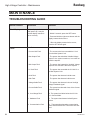
1
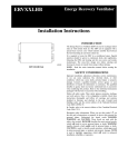
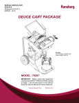
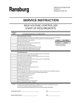
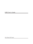
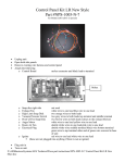
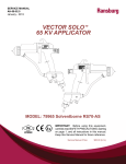
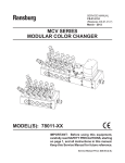
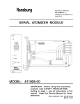
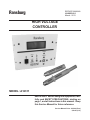
Ransburg SERVICE MANUAL LN-9623-00.1 March - 2013 HIGH VOLTAGE CONTROLLER MODEL: A12311 IMPORTANT: Before using this equipment, carefully read SAFETY PRECAUTIONS, starting on page 1, and all instructions in this manual. Keep this Service Manual for future reference. Service Manual Price: €25.00 (Euro) $30.00 (U.S.) Ransburg High Voltage Controller - Contents CONTENTS SAFETY: PAGE 1-5 SAFETY PRECAUTIONS......................................................................................................... 1 HAZARDS / SAFEGUARDS..................................................................................................... 2-5 INTRODUCTION: 6-9 GENERAL DESCRIPTION....................................................................................................... 6 SAFETY FEATURES................................................................................................................ 6 DISPLAY................................................................................................................................... 6 SPECIFICATIONS.................................................................................................................... 7 PASSWORD PROTECTION.................................................................................................... 8 OPERATOR INTERFACE........................................................................................................ 8 SWITCHES.............................................................................................................................. 8 LED'S....................................................................................................................................... 8-9 BUTTONS................................................................................................................................ 9 INSTALLATION: 10-11 INSTALLATION..........................................................................................................................10 MOUNTING................................................................................................................................10 INPUT POWER CONNECTIONS............................................................................................. 10 ETHERNET CONNECTOR.......................................................................................................11 INTERLOCK CONNECTION.................................................................................................... 11 OUTPUT TO CASCADE........................................................................................................... 11 RS232 CONNECTOR................................................................................................................11 OPERATION: 12-20 MENUS AND OPERATION.......................................................................................................12-14 PARAMETERS AND SETTINGS.............................................................................................. 14 CONTROL CONDITIONS.........................................................................................................15 SYSTEM STATUS (STS)...........................................................................................................15 SYSTEM CHECK (CHK)...........................................................................................................15 ETHERNET IP INTERFACE..................................................................................................... 16-20 MAINTENANCE: 21 TROUBLESHOOTING GUIDE................................................................................................. 21 WARRANTY POLICIES: 22 LIMITED WARRANTY...............................................................................................................22 LN-9623-00.1 2 Ransburg High Voltage Controller - Safety SAFETY SAFETY PRECAUTIONS Before operating, maintaining or servicing any Ransburg electrostatic coating system, read and understand all of the technical and safety literature for your Ransburg products. This manual contains information that is important for you to know and understand. This information relates to USER SAFETY and PREVENTING EQUIPMENT PROBLEMS. To help you recognize this information, we use the following symbols. Please pay particular attention to these sections. A WARNING! states information to alert you to a situation that might cause serious injury if instructions are not followed. A CAUTION! states information that tells how to prevent damage to equipment or how to avoid a situation that might cause minor injury. A NOTE is information relevant to the procedure in progress. While this manual lists standard specifications and service procedures, some minor deviations may be found between this literature and your equipment. Differences in local codes and plant requirements, material delivery requirements, etc., make such variations inevitable. Compare this manual with your system installation drawings and appropriate Ransburg equipment manuals to reconcile such differences. ! WARNING The user MUST read and be familiar with the Safety Section in this manual and the Ransburg safety literature therein identified. This manual MUST be read and thoroughly understood by ALL personnel who operate, clean or maintain this equipment! Special care should be taken to ensure that the WARNINGS and safety requirements for operating and servicing the equipment are followed. The user should be aware of and adhere to ALL local building and fire codes and ordinances as well as NFPA-33 SAFETY STANDARD, LATEST EDITION, prior to installing, operating, and/or servicing this equipment. ! WARNING The hazards shown on the following pages may occur during the normal use of this equipment. Please read the hazard chart beginning on page 2. Careful study and continued use of this manual will provide a better understanding of the equipment and process, resulting in more efficient operation, longer trouble-free service and faster, easier troubleshooting. If you do not have the manuals and safety literature for your Ransburg system, contact your local Ransburg representative or Ransburg. 1 LN-9623-00.1 Ransburg High Voltage Controller - Safety AREA HAZARD Spray Area Fire Hazard Tells where hazards may occur. Tells what the hazard is. Improper or inadequate operation and maintenance procedures will cause a fire hazard. Protection against inadvertent arcing that is capable of causing fire or explosion is lost if any safety interlocks are disabled during operation. Frequent Power Supply or Controller shutdown indicates a problem in the system requiring correction. SAFEGUARDS Tells how to avoid the hazard. Fire extinguishing equipment must be present in the spray area and tested periodically. Spray areas must be kept clean to prevent the accumulation of combustible residues. Smoking must never be allowed in the spray area. The high voltage supplied to the atomizer must be turned off prior to cleaning, flushing or maintenance. When using solvents for cleaning: •• Those used for equipment flushing should have flash points equal to or higher than those of the coating material. •• Those used for general cleaning must have flash points above 100°F (37.8°C). Spray booth ventilation must be kept at the rates required by NFPA-33, OSHA, country, and local codes. In addition, ventilation must be maintained during cleaning operations using flammable or combustible solvents. Electrostatic arcing must be prevented. Safe sparking distance must be maintained between the parts being coated and the applicator. A distance of 1 inch for every 10KV of output voltage is required at all times. Test only in areas free of combustible material. Testing may require high voltage to be on, but only as instructed. Non-factory replacement parts or unauthorized equipment modifications may cause fire or injury. If used, the key switch bypass is intended for use only during setup operations. Production should never be done with safety interlocks disabled. Never use equipment intended for use in waterborne installations to spray solvent based materials. The paint process and equipment should be set up and operated in accordance with NFPA33, NEC, OSHA, local, country, and European Health and Safety Norms. LN-9623-00.1 2 Ransburg High Voltage Controller - Safety AREA Tells where hazards may occur. Spray Area HAZARD Tells what the hazard is. SAFEGUARDS Tells how to avoid the hazard. Explosion Hazard Improper or inadequate operation and maintenance procedures will cause a fire hazard. Protection against inadvertent arcing that is capable of causing fire or explosion is lost if any safety interlocks are disabled during operation. Frequent Power Supply or Controller shutdown indicates a problem in the system requiring correction. Electrostatic arcing must be prevented. Safe sparking distance must be maintained between the parts being coated and the applicator. A distance of 1 inch for every 10KV of output voltage is required at all times. Unless specifically approved for use in hazardous locations, all electrical equipment must be located outside Class I or II, Division 1 or 2 hazardous areas, in accordance with NFPA-33. Test only in areas free of flammable or combustible materials. The current overload sensitivity (if equipped) MUST be set as described in the corresponding section of the equipment manual. Protection against inadvertent arcing that is capable of causing fire or explosion is lost if the current overload sensitivity is not properly set. Frequent power supply shutdown indicates a problem in the system which requires correction. Always turn the control panel power off prior to flushing, cleaning, or working on spray system equipment. Before turning high voltage on, make sure no objects are within the safe sparking distance. Ensure that the control panel is interlocked with the ventilation system and conveyor in accordance with NFPA-33, EN 50176. Have fire extinguishing equipment readily available and tested periodically. General Use and Maintenance Improper operation or maintenance may create a hazard. Personnel must be given training in accordance with the requirements of NFPA-33, EN 60079-0. Personnel must be properly trained in the use of this equipment. Instructions and safety precautions must be read and understood prior to using this equipment. Comply with appropriate local, state, and national codes governing ventilation, fire protection, operation maintenance, and housekeeping. Reference OSHA, NFPA-33, EN Norms and your insurance company requirements. 3 LN-9623-00.1 Ransburg AREA Tells where hazards may occur. Spray Area / High Voltage Equipment High Voltage Controller - Safety HAZARD Tells what the hazard is. SAFEGUARDS Tells how to avoid the hazard. Electrical Discharge There is a high voltage device that can induce an electrical charge on ungrounded objects which is capable of igniting coating materials. Inadequate grounding will cause a spark hazard. A spark can ignite many coating materials and cause a fire or explosion. Parts being sprayed and operators in the spray area must be properly grounded. Parts being sprayed must be supported on conveyors or hangers that are properly grounded. The resistance between the part and earth ground must not exceed 1 meg ohm. (Refer to NFPA-33.) Operators must be grounded. Rubber soled insulating shoes should not be worn. Grounding straps on wrists or legs may be used to assure adequate ground contact. Operators must not be wearing or carrying any ungrounded metal objects. When using an electrostatic handgun, operators must assure contact with the handle of the applicator via conductive gloves or gloves with the palm section cut out. NOTE: REFER TO NFPA-33 OR SPECIFIC COUNTRY SAFETY CODES REGARDING PROPER OPERATOR GROUNDING. All electrically conductive objects in the spray area, with the exception of those objects required by the process to be at high voltage, must be grounded. Grounded conductive flooring must be provided in the spray area. Always turn off the power supply prior to flushing, cleaning, or working on spray system equipment. Unless specifically approved for use in hazardous locations, all electrical equipment must be located outside Class I or II, Division 1 or 2 hazardous areas, in accordance with NFPA-33. LN-9623-00.1 4 Ransburg High Voltage Controller - Safety AREA Tells where hazards may occur. Electrical Equipment HAZARD Tells what the hazard is. Tells how to avoid the hazard. Electrical Discharge An electrical arc can ignite coating materials and cause a fire or explosion. Unless specifically approved for use in hazardous locations, the power supply, control cabinet, and all other electrical equipment must be located outside Class I or II, Division 1 and 2 hazardous areas in accordance with NFPA-33 and EN 50176. Turn the power supply OFF before working on the equipment. Test only in areas free of flammable or combustible material. Testing may require high voltage to be on, but only as instructed. Production should never be done with the safety circuits disabled. Before turning the high voltage on, make sure no objects are within the sparking distance. Certain material may be harmful if inhaled, or if there is contact with the skin. Follow the requirements of the Material Safety Data Sheet supplied by coating material manufacturer. High voltage equipment is utilized in the process. Arcing in the vicinity of flammable or combustible materials may occur. Personnel are exposed to high voltage during operation and maintenance. Protection against inadvertent arcing that may cause a fire or explosion is lost if safety circuits are disabled during operation. Frequent power supply shutdown indicates a problem in the system which requires correction. Toxic Substances SAFEGUARDS Adequate exhaust must be provided to keep the air free of accumulations of toxic materials. Use a mask or respirator whenever there is a chance of inhaling sprayed materials. The mask must be compatible with the material being sprayed and its concentration. Equipment must be as prescribed by an industrial hygienist or safety expert, and be NIOSH approved. Spray Area Explosion Hazard – Incompatible Materials Halogenated hydrocarbon solvents for example: methylene chloride and 1,1,1,-Trichloroethane are not chemically compatible with the aluminum that might be used in many system components. The chemical reaction caused by these solvents reacting with aluminum can become violent and lead to an equipment explosion. 5 Aluminum is widely used in other spray application equipment - such as material pumps, regulators, triggering valves, etc. Halogenated hydrocarbon solvents must never be used with aluminum equipment during spraying, flushing, or cleaning. Read the label or data sheet for the material you intend to spray. If in doubt as to whether or not a coating or cleaning material is compatible, contact your coating supplier. Any other type of solvent may be used with aluminum equipment. LN-9623-00.1 Ransburg High Voltage Controller - Introduction INTRODUCTION GENERAL DESCRIPTION The Ransburg High Voltage Controller (A1231100 or FRA # EE-4526-300), in conjunction with an appropriate cascade (A12295-00 [FRA# EE-4526800] or A12296-00 [FRA# EE- 4626-801]), is used to provide high voltage for electrostatic application equipment. The controller is packaged in a single package measuring 5.5" tall X 7.5" wide X 3.5 “ deep. The controller can operate in “Local” and “Remote” conditions with either “Voltage Mode” or “Current Mode” of high voltage operation. The Ransburg High Voltage Controller uses a combination of proven high voltage generation technology including microprocessor-based control with diagnostic and communication functions. It uses a variable voltage output to drive a cascade that amplifies the voltage to a high value. It also uses feedback with both current and voltage information to attempt to maintain actual value at set point. The processor circuitry provides the maximum in applicator transfer efficiency, while maintaining the maximum safety. DISPLAY The front panel displays the high voltage and current output from the cascade as true readings. They are derived from feedback signals in the low voltage cable between the controller and the cascade. Figure 1: High Voltage Controller SAFETY FEATURES When used with the appropriate applicators and cascades, the Ransburg High Voltage Controller provides the ultimate in operational safety. The protections include Overvoltage, Overcurrent, Di/ Dt and Dv/Dt. The microprocessor circuits allow the use of the output load curve control, which limits the high voltage output to safe levels when the controls are set responsibly and safe distances are observed and followed. LN-9623-00.1 6 Ransburg High Voltage Controller - Introduction SPECIFICATIONS NOTES Environmental / Physical Operating Temperature: 0°C to +55°C Storage and Shipping Temperature: -40°C to +85°C Humidity: Physical Size: 95% Non-Condensing 5.5" tall X 7.5" wide X 3.5" deep Electrical Power Required: 24VDC ± .5 V @ 2.5 Amps maximum (@ sea- level), regulated, with over-voltage protection. Note: For every 1000 ft. of increased elevation, the maximum current is increased by 3%. High Voltage Output: 24 Volts, 1Amp, Form C relay contact Controller Operating Range High Voltage: 0-100kV, settable in 1kV increments Current: 0-150 microamps Communication Requirements Control and Reporting: Ethernet IP Note: A unique MAC ID address is hard coded into each High Voltage Controller. User con-trols must be configured to recognize each unique address. Internal Controller Scan Time: 7 1 ms (all data is taken from a rolling average of 8 scans) LN-9623-00.1 Ransburg High Voltage Controller - Introduction PASSWORD PROTECTION High Voltage Controller parameters will be password protected to prevent an unqualified operator from changing the values. Figure 2: Password Screen OPERATOR INTERFACE The High Voltage Controller has a physically simple operator interface consisting of three (3) LED's (Light Emitting Diodes), three (3) switches, six (6) buttons, and a four line twenty character (4 X 20) alpha/numeric display. SWITCHES Power Switch The rocker switch on the left and the LED directly above it are for power On/Off selection and display. The green LED is on when the power is On to the controller. Local/Remote Switch This is used to determine if the Local (Front Panel) controls have priority or if the Remote (Ethernet Connection) controls have priority. If the switch is up (Local Mode) the Front Panel controls may change parameters, enable or disable the high voltage, and clear faults. The Remote Ethernet connection may look at parameters and values, but may not change them or enable/disable the high voltage output. If the switch is down (Remote Mode) the opposite is true except that the Front Panel switch may be changed to local Mode at any time to disable the Remote Controls and to enable the Local Controls. HV On/Off Switch This is a floating toggle switch. It is active if the Local/Remote mode switch is in Local. It is used to enable and disable the High Voltage output and to clear system faults. When the System Checks and Current Status are OK flipping the switch to the up position (HV On) will enable High Voltage Output (see "Figure 3 - Power Swtich" in this section). Flipping it to the down position (HV Off) will disable the High Voltage Output. If there is a system fault, flipping this switch to the OFF position (also known as the Reset position) it will reset (clear) any faults currently detected by the system. LED'S Power LED If the Green Power LED is on, then the system power to the controller is On. Figure 3: Power Switch LN-9623-00.1 8 Ransburg High Voltage Controller - Introduction Fault LED The red Fault LED is lit when the system detects a fault condition (see "Figure 3 - Power Switch" in this section). When operating in "Local Mode", it is cleared by flipping the HV On/Off switch to the Off (Reset) position. If the system is still in a fault condition, it will immediately be lit as the system detects the fault. NOTES High Voltage LED The green High Voltage LED displays the current state of the High Voltage Output. This LED is illuminated whenever High Voltage is being supplied. BUTTONS The six buttons used to control the viewing and entry of information on the 4 X 20 character display are: Screen Button The Screen Button (at the top) is used to change (toggle) to the next Menu screen. The menu screens wrap around so that after the last screen it will return to the first screen. Up and Down Buttons The buttons above and below the Set Button in the middle (the Up and Down Buttons) are used to change which value on the screen is to be changed. Set Button This labeled button (in the middle) is used to select the value to change and to enter the change after it has been made. Increase and Decrease Buttons The buttons to the right and left of the Set Button are the Increase and Decrease Buttons. They are used to change the value selected by the Set Button. 9 LN-9623-00.1 Ransburg High Voltage Controller - Installation INSTALLATION INSTALLATION INPUT POWER CONNECTIONS Figure 4: Installation MOUNTING Using four (4) each 10" X 32" or M-5 screws (not included), secure the front panel of the High Voltage Controller, using the supplied mounting holes, to enclosure. Figure 5: Input Power Connections Input power must be supplied from a regulated DC power Supply. The connection is made at J8 with +VIN at 24VDC ± .5V, GND at 24VDC return, CGND at Earth Ground. The 24 VDC supply must be protected against excessive current as well as Over Voltage protected. NOTE > The Ransburg High Voltage Controller has a built in resettable fuse so if it draws a current in excess of 2.5 amps it will open. Reset is achieved by turning controller power OFF for 5 minutes then back ON. LN-9623-00.1 10 Ransburg High Voltage Controller - Installation ETHERNET CONNECTOR are marked as COM (Common) NC (normally closed) or NO (normally open) and can be used by end-user. OUTPUT TO CASCADE Make connections from J6 of the controller to, the cascade per the following table. Figure 6: Ethernet Connector Use the appropriate 10/100BASE Ethernet wiring (Straight EIA/TIA 568A) for your installation using a RJ-45 plug to connect to the High Voltage Controller. INTERLOCK CONNECTION Figure 8: Output to Cascade TABLE 1 HVC-J6 Cascade A12295-00 (FRA# EE-4526-800) or A12296-00 (FRA# EE- 4626-801) HVGND Pin 1 R+ Pin 2 E+ Pin 3 GND Pin 4 U-FB Pin 5 SC Pin 6 I-FB Pin 7 OVDC for R+ and E+ Power Analog DC Cascade Drive Signal Nominal 15VDC for Cascade Electronics 0VDC for Analog Cascade Voltage Feedback Analog Cascade Voltage Feedback Signal 0VDC for Analog Cascade Current Feedback Analog Cascade Current Feedback Signal Figure 7: Interlock Connection J9 is supplied to give a hardwire connection thru relay dry contacts (rated at 24 VDC @ 1 amp maximum) for when the controller operating power is turned OFF or a fault condition exists. They 11 RS232 CONNECTOR This connector is a service connection for the Ransburg factory. LN-9623-00.1 Ransburg High Voltage Controller - Operation OPERATION MENUS AND OPERATION On all of the menus, if there is a parameter that can be changed there are a number of "#" characters to show that it is an enterable value. If there is more than one enterable value, pressing the Up or Down Buttons will move the "#'s" to the next changeable value. When the "#'s" are next to the value you wish to change, press the Set Button. This will bring up the Password Menu to allow you to enter the password and change the value. Once the password has been entered, it will remain active for an appropriate amount of time and then time out, requiring you to re-enter it. This is the menu that displays on the unit for 5 seconds (approximately) at power up. It displays the Model Number, Copyright Date, Serial Number, Software Version, and Hardware Version of the unit. It then changes to the Run Menu. If the Set Button is pressed while this menu is still up, the system changes to the display contrast Menu automatically to allow for contrast adjustment on initial power up. Run Menu When a valid password has been entered for any value (even if the value has not been changed) different menus will be available. These Menus are the Display Contrast Menu, the IP Address Menu, and the Enter New Password Menu. When a numeric value is being changed (using the buttons to the left and right of the SET Button) the numeric will increase with the right button and decrease with the left button until it passes the maximum or minimum allowed value at which time it will "roll over" to the other limit. Start-Up Menu Figure 10: Run Menu Screen This menu displays the setpoint (KVSET if in Voltage Mode, uASET if in Current Mode), the current actual KV value, the current uA value, the current hardware check value, the High Voltage status, and the current controller status. The setpoint (KVSET or uASET) is the only changeable value on this menu. Figure 9: Start-Up Menu Screen LN-9623-00.1 12 Ransburg High Voltage Controller - Operation Mode Menu Fault Menu Figure 11: Voltage Mode Screen Figure 13: Fault Menu Screen This menu displays the current mode (Voltage or Current) and the high and low limits allowed for the Dependent Value in that mode. All of these values are changeable values. This menu displays the latest fault and is displayed automatically upon the fault detection. Sensitivity Menu Display Contrast Menu Figure 12: Sensitivity Menu Screen This menu displays the current di/dt or dv/dt limit value and the enable status for di/dt or dv/dt depending on the mode. These are changeable values. If the current/voltage changes greater than this value within approximately 100ms, a fault signal is issued. 13 Figure 14: Display Contrast Menu Screen below the password digit being changed instead of beside them. When the new password is entered, it will now be used for all values being changed. LN-9623-00.1 Ransburg IP Address Menu High Voltage Controller - Operation PARAMETERS AND SETTINGS Mode The operating mode can be set to either Voltage or Current mode. The mode selection determines which independent setpoint is the basis for control. kVSet Figure 14: IP Address Menu Screen This is the voltage setpoint, used in Voltage Mode. The system attempts to keep the voltage at this value. uASet This menu allows the setting of the units IP Address. When the new IP Address has been entered, the unit must have the power cycled before the new IP Address will be used. This is the current setpoint, used in Current Mode. The system attempts to keep the current at this value. Password Menu This parameter determines the level where a kV Limit Fault occurs. When the voltage rises above this value, it issues a kV Limit Fault. It only applies in Current Mode. This menu is different in that the "#'s" are displayed below the password digit being changed instead of beside them. When the password is entered, the menu will return to the value being changed. Enter New Password Menu This menu is different in that the "#'s" are displayed below the password digit being changed instead of beside them. When the new password is entered, it will now be used for all values being changed. kV Limit Hi kV Limit Lo This parameter determines the level where a kV Limit Fault occurs. When the Voltage falls below this value, it issues a kV Limit Fault. It only applies in Current Mode. uA Limit Hi This parameter determines the level where a Current Limit Fault occurs. When the current rises above this value, it issues a Current Limit Fault. It only applies in Voltage Mode. Di/dt Sensitivity When a rapid current change occurs where current rises faster than this value in approximately 100ms, it issues a di/dt fault. This is only active in Voltage Mode. Dv/dt Sensitivity When a rapid voltage change occurs where voltage falls faster than this value in approximately 100ms it issues a dv/dt fault. This is only active in Current Mode. LN-9623-00.1 14 Ransburg High Voltage Controller - Operation CONTROL CONDITIONS SYSTEM STATUS (STS) Power Up OK On power up, the system does several checks to determine hardware status. It checks various signals to determine that there are no faults, including feedback from the Variable Voltage Output and High Voltage Inputs to determine system status. If it determines that it is OK to start, the Check display on the run menu changes from NoGo to OK and System Status changes to OK. HV On When the HV On signal is received, the system status changes to "Starting" and the Variable Voltage Output is increased until the Indpendent Value rises to within a tolerance window (currently +/-3) of the setpoint value. Then the System Status changes to "Running". Setpoint Changed If the setpoint changes outside the control window, the status changes to "Rising" or "Falling" until the Independent Value again reaches the window at which point it returns to "Running". HV Off On HV Off the system immediately sets the Variable Voltage Output to zero volts, disables the HV Relay and goes to Stop Mode. The System Check goes to NoGo until the High Voltage and Variable Voltage Output feedback again reach the pre-determined value. System is off and ready to start. Starting/Rising/Falling System is changing from one voltage/current value to another. Di/dt and dv/dt checks are disabled. Running System is attempting to keep a steady value on Setpoint (the Independent Value). All enabled checks are active. Stopping System is off and waiting to transient voltages/ currents to stop. Warning System has detected a current or voltage condition within 10% of the limit settings. Fault System has detected a fault condition, stopped and will not allow starting until the fault is cleared. If the fault condition has not been cleared, it may immediately fault without starting. SYSTEM CHECK (CHK) OK System has passed the checks and is ready to start. NoGo System has detected excessive voltage on the High Voltage or Variable Voltage Output Feedbacks and will not allow a start. 15 LN-9623-00.1 Ransburg High Voltage Controller - Operation ETHERNET IP INTERFACE The Ethernet IP Interface is defined as a set of four 16 bit IO words of input and a set of four 16 bit words of output. The Ethernet IP Input Assembly is defined as object 0 X 70 and the Ethernet IP Output Assembly is defined as object 0 X 71. The bit definitions are in the following table: ETHERNET IP INPUT BIT DEFINITIONS TABLE 1 LN-9623-00.1 16 Ransburg High Voltage Controller - Operation Input Word 0 Input Word 3 These bits are currentely undefined and unused. Bit 0 - Enable Control When this bit is set (high) the system will attempt to keep the actual at the appropriate setpoint. Bit 1 - Reset Faults When this bit is changed from low to high (cleared to set) the system will clear any fault bits if any are set and will set the communication fault if no fault bits are set. Bit 2 - Current Mode When this bit is set, the system will Bits (0-7) - Unused Bits (8-14) - Parameter Select code The 7 bit value determines the parameter to change. Bit 15 - Parameter Read Strobe When this bit changes from cleared, to set the Current Parameter Value is read from the selected parameter and displayed in the Output Word 3. operate in the Current Control Mode and when cleared will operate in the Voltage Control Mode. Bit 3 (3-15) - Unused These bits are currently undefined and unused. Input Word 1 Bits (0-7) - kV Setpoint This byte (8 bit) value determines the active Voltage setpoint in kV. Bits (8-15) - uA Setpoint This byte (8 bit) value determines the active Current setpoint in uA. Input Word 2 Bits (0-7) - Parameter Value These bits are currently undefined and unused. Bit (8-14) - Parameter Select Code This 7 bit value determines the parameter to change. Bit 15 - Parameter Write Strobe 17 When this bit changes from cleared to set, the parameter value is written into the selected parameter and displayed in the Output Word 2. LN-9623-00.1 Ransburg High Voltage Controller - Operation ETHERNET IP OUTPUT BIT DEFINITIONS TABLE 2 LN-9623-00.1 18 Ransburg High Voltage Controller - Operation Output Word 0 Output Word 1 Bit 0 - In Control This bit is set when control is enabled and the control value has closed within three of the setpoint. This does not mean that the value is still within three of the setpoint, but that it had been at one time. Bit 1 - Ramping This bit is set when the setpoint has been changed and the current value has not come within three of the setpoint yet. During the time it is set, the di/dt and dv/ dt are not active. Bit 2 - OK to Start This bit is set when the system determines that the current voltage values are in a range where it is allowed to start control. Bit 3 - Remote Mode This bit is set when the front panel switch is set to remote in order to allow remote control of the system. Bit 4 - HV On Echo This bit is set whenever HV is ON Bit 5 - Warning This bit is set whenever any warning is in effect. Bit 6 - Fault This bit is set whenever any fault is in effect (see "Fault Descriptions" in "Troubleshooting Guide" in the "Maintenance" section). Bit (7-14) - Unused These bits are currently undefined and unused. Bit 15 - Heartbeat This bit changes state every 1/4 second producing two pulses per second. Bit 0 - Over Current Warning The current value is within 10% of the upper limit. Bit 1 - Over Voltage Warning The voltage value is within 10% of the upper limit in current mode. Bit 2 - Under Voltage Warning The voltage value is within 10% of the lower limit in current mode. Bit (3-5) - Unused These bits are currently undefined and unused. Bit 6 - Communication Fault The system has detected a communi- cation failure after an Ethernet IP connection was initiated. Bit 7 - Hardware Fault The system has detected a fatal System Failure. Bit 8 - Low Voltage Fault The system has fallen below the kV Limit Lo in Current Mode. Bit 9 - dv/dt Fault The system has detected a di/dt event. Bit 10 - di/dt Fault The system has detected a di/dt event. Bit 11 - Minimum Output Fault The system has lowered the Variable Voltage Output to zero and still is above the setpoint. Bit 12 - Maximum Output Fault The system has raised the Variable Voltage Output to the system maximum, but could not reach the setpoint. Bit 13 - Over Voltage Fault 19 The system has exceeded the kV Limit Hi or the Max System Limit. LN-9623-00.1 Ransburg Bit 14 - Over Current Fault The current value has exceeded the Current (I) Limit Hi or the Max System Limit. High Voltage Controller - Operation NOTES Bit 15 - Cable Fault This bit is set whenever the voltage or current feedback from the cascade has been lost or fallen below the acceptable value. Output Word 2 Bits (0-7) - Parameter Data Value This byte (8 bit) tells the system the active parameter value. Bits (8-14) - Parameter Select Code This 7 bit value tells the system which parameter is being displayed. Bit 15 - Parameter Acknowledge When this bit changes from cleared to set a new Parameter Value is being displayed. It is cleared when the Parameter Read Strobe and Parameter Write Strobe are both cleared. Output Word 3 Bits (0-7) - Actual kV Value The byte (8 bit) value displays the latest voltage reading in kV. Bits (8-15) - Actual uA Value LN-9623-00.1 This byte (8 bit) value displays the latest current reading in uA. 20 Ransburg High Voltage Controller - Maintenance MAINTENANCE TROUBLESHOOTING GUIDE General Problem Blank Display Procedure 1. If the display is blank on initial power-up, it may be that the display contrast is not set correctly. Solution 1. Cycle the Power on the unit. 2. Within 5 seconds, press the SET button. 3. Press and hold the right arrow button until the display contrast looks correct. 4. When the display contrast looks correct, press the SET button again. Faults 21 1. No Fault 1. No Fault was detected. 2. Current Limit Fault 2. The current value has exceeded the I Limit Hi or the Max System Limit. 3. Max Output Fault 3. The system has raised the Variable Voltage Output to the system maximum, but could not reach the setpoint. 4. Min Output Fault 4. The system has lowered the Variable Voltage Output to zero and still is above the setpoint. 5. kV Limit Fault 5. The system has exceeded the kV Limit Hi or the Max System Limit. 6. dv/dt Fault 6. The system has detected a dv/dt event. 7. di/dt Fault 7. The system has detected a di/dt event. 8. Voltage Cable Fault 8. The system has detected a loss of the High Voltage Feedback signal. 9. Current Cable Fault 9. The system has detected a loss of the Current Feedback signal. 10. Low Voltage Fault 10. The system has fallen below the kV Limit Lo in Current Mode. 11. Hardware Fault 11. The system has detected a fatal System Failure. 12. Communication Fault 12. The system has detected a communication failure after an Ethernet IP connection was initiated. LN-9623-00.1 Ransburg High Voltage Controller - Warranty Policies WARRANTY POLICIES LIMITED WARRANTY Ransburg will replace or repair without charge any part and/or equipment that falls within the specified time (see below) because of faulty workmanship or material, provided that the equipment has been used and maintained in accordance with Ransburg's written safety and operating instructions, and has been used under normal operating conditions. Normal wear items are excluded. THE USE OF OTHER THAN RANSBURG APPROVED PARTS, VOID ALL WARRANTIES. SPARE PARTS: One hundred and eighty (180) days from date of purchase, except for rebuilt parts (any part number ending in "R") for which the warranty period is ninety (90) days. EQUIPMENT: When purchased as a complete unit, (i.e., guns, power supplies, control units, etc.), is one (1) year from date of purchase. WRAPPING THE APPLICATOR, ASSOCIATED VALVES AND TUBING, AND SUPPORTING HARDWARE IN PLASTIC, SHRINK-WRAP, OR ANY OTHER NON-APPROVED COVERING, WILL VOID THIS WARRANTY. LN-9623-00.1 RANSBURG'S ONLY OBLIGATION UNDER THIS WARRANTY IS TO REPLACE PARTS THAT HAVE FAILED BECAUSE OF FAULTY WORKMANSHIP OR MATERIALS. THERE ARE NO IMPLIED WARRANTIES NOR WARRANTIES OF EITHER MERCHANTABILITY OR FITNESS FOR A PARTICULAR PURPOSE. RANSBURG ASSUMES NO LIABILITY FOR INJURY, DAMAGE TO PROPERTY OR FOR CONSEQUENTIAL DAMAGES FOR LOSS OF GOODWILL OR PRODUCTION OR INCOME, WHICH RESULT FROM USE OR MISUSE OF THE EQUIPMENT BY PURCHASER OR OTHERS. EXCLUSIONS: If, in Ransburg's opinion the warranty item in question, or other items damaged by this part was improperly installed, operated or maintained, Ransburg will assume no responsibility for repair or replacement of the item or items. The purchaser, therefore will assume all responsibility for any cost of repair or replacement and service related costs if applicable. 22 Service Manual Price: €25.00 (Euro) $30.00 (U.S.) Manufacturing 1910 North Wayne Street Angola, Indiana 46703-9100 Telephone: 260/665-8800 Fax: 260/665-8516 www.ransburg.com Technical/Service Assistance Telephone: 800/ 233-3366 Fax: 419/ 470-2071 Technical Support Representative will direct you to the appropriate telephone number for ordering Spare Parts. © 2013 Ransburg. All rights reserved. Models and specifications subject to change without notice. Form No. LN-9623-00.1 Litho in U.S.A. 03/13