1
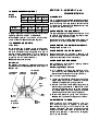
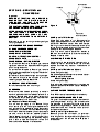
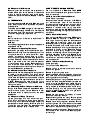
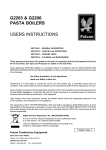
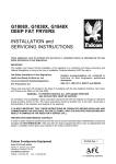
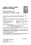
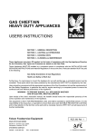
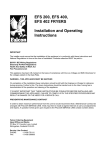
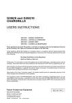
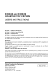
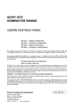
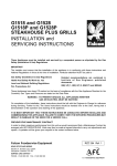
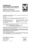
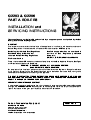
G2203 & G2206
PASTA BOILERS
INSTALLATION and
SERVICING INSTRUCTIONS
These appliances must be installed and serviced by a competent person as stipulated by the Gas
Safety (Installation & Use) Regulations.
IMPORTANT
The installer must ensure that the installation of the appliance is in conformity with these instructions and
National Regulations in force at the time of installation. Particular attention MUST be paid to -
Gas Safety (Installation & Use) Regulations
Health And Safety At Work etc. Act
Local and National Building Regulations
Fire Precautions Act
Detailed recommendations are contained in
Institute of Gas Engineers published
documents :
IGE/ UP/ 1, IGE/ UP/ 2, BS6173 and BS5440
These units have been CE-marked on the basis of compliance with the Gas Appliance Directive, Gas Types
and Pressures as stated on the Data Plate.
WARNING - TO PREVENT SHOCKS, ALL APPLIANCES WHETHER
GAS OR ELECTRIC, MUST BE EARTHED
On completion of the installation, these instructions should be left with the Engineer-in-Charge for reference
during servicing. Further to this, The Users Instructions should be handed over to the User, having had a
demonstration of the operation and cleaning of the appliance.
IT IS MOST IMPORTANT THAT THESE INSTRUCTIONS BE CONSULTED BEFORE INSTALLING AND
COMMISSIONING THIS APPLIANCE. FAILURE TO COMPLY WITH THE SPECIFIED PROCEDURES MAY
RESULT IN DAMAGE OR THE NEED FOR A SERVICE CALL.
PREVENTATIVE MAINTENANCE CONTRACT
In order to obtain maximum performance from this unit we would recommend that a Maintenance Contract be
arranged with AFE SERVICELINE. Visits may then be made at agreed intervals to carry out adjustments and
repairs. A quotation will be given upon request to the contact numbers below.
Falcon Foodservice Equipment
HEAD OFFICE AND WORKS
PO Box 37, Foundry Loan, Larbert.
Stirlingshire. Scotland. FK5 4PL
AFE SERVICELINE CONTACT -
PHONE - 01438 363 000 FAX - 01438 369 900
R5094 Ref. 3
SECTION 1 - INSTALLATION
UNLESS OTHERWISE STATED, PARTS WHICH HAVE BEEN PROTECTED BY THE MANUFACTURER
ARE NOT TO BE ADJUSTED BY THE INSTALLER
1.1 MODEL NUMBERS, NETT WEIGHTS
and DIMENSIONS
1.4 GAS SUPPLY
The incoming service must be of sufficient size to
supply full rate gas without excessive pressure drop.
DEPTH HEIGHT WEIGHT WEIGHT
MODEL WIDTH
A gas meter is connected to the service pipe by the
mm
mm
mm
kg
lbs
Gas Supplier. Any existing meter should be checked
G2203
300 770 870 56.7 125 by the Gas Supplier to ensure that such a meter is of
adequate capacity to pass the required rate of gas for
G2206
600 770 870 76.2 168 the unit, in addition to any other gas equipment which
has been installed.
The unit should be installed on a level, fireproof floor The gas control unit has an in-built governor therefore
in a well lit, draught free position. A clear space of an external device does not require to be fitted.
150mm should be left between the rear and sides of
Installation pipework should be fitted in accordance
the pasta boiler and any combustible wall.
with IGE/UP/2. Pipework should not be smaller than
the gas inlet connection - G2203 - Rp1/2 (1/2" BSP)
1.3 VENTILATION
and G2206 - Rp3/4 (3/4" BSP) .
Adequate ventilation, either natural or mechanical,
must be provided to supply sufficient fresh air for An isolating cock must be located close to the unit to
combustion. This should allow easy removal of allow shutdown during an emergency or servicing.
combustion products which may be harmful to health. The installation should be checked for gas soundness
and purged as specified in IGE/UP/1.
Recommendations for Ventilation of Catering
Appliances are given in BS5440:2. Furthermore, to 1.5 ELECTRICAL SUPPLY
ensure sufficient room ventilation, guidance on the
volume of air required to ventilate different types of Not applicable to these units.
catering equipment is provided in the table below.
For multiple installations, the requirements for 1.6 WATER SUPPLY
individual units require to be added together. The appliance is intended for connection to a main
Installation should be carried out in accordance with water supply only. Supply pressure must be within the
local and/or national regulations which apply at the range of 2.5 to 7.5 bar. A stop cock must be fitted in
an easily accessible position on the supply to enable
time. A competent installer MUST be employed.
The flue discharges vertically at the appliance rear at shut off for cleaning and maintenance.
a height of 1 metre from floor level. A clear distance of
610mm must be left between the top edge of the flue 1.7 TOTAL GAS RATES NATURAL and PROPANE GAS
and any overhanging object.
There must be no direct connection of the flue to the
Model
kW
Btu/hr
outside air or to a mechanical extraction system.
G2203
18.1
61,757
Placing the unit below a ventilated canopy is the most
G2206
32.5
110,890
suitable arrangement.
EQUIPMENT
Range, Unit Type
Pastry Oven
Fryer
Grill
Steak Grill
Boiling Pan
Steamer
Sterilizing Sink
Bains Marie
Tea/Coffee Machine
Pasta Boiler
Ventilation Rate Required
m3/ min
ft3/min
17
17
26
17
26
17
17
14
11
8.5 - 14
26
600
600
900
600
900
600
600
500
400
300 - 500
900
1.8 INJECTOR SIZES 1.8.1 Natural Gas
Model
G2203
G2206
Pilot Burner Main Burner
NG No. 18 é2.38mm
NG No. 18
é3.2mm
1.8.2 Propane Gas
Model
G2203
G2206
Pilot Burner Main Burner
LP No. 11
é1.57mm
LP No. 11
é2.15mm
1.8.3 Cross-Lighting Burners
Natural Gas Propane Gas
NG No. 26 LP No. 16
1.9 GAS PRESSURE ADJUSTMENT
Supply
Pressures
Model
G2203/2206
Natural Gas
mbar in. w.g
20
8
Propane Gas
mbar in. w.g
37
14.8
Natural Gas
mbar in. w.g
15
6
Propane Gas
mbar in. w.g
34.5
13.8
A pressure test point is fitted on burner manifold and
operating pressure is shown in table above.
An adjustable governor is included in multifunctional
control on Natural Gas models (see Figure 1).
1.10 BURNER ADJUSTMENTS
1.10.1 Pilot
Main Burner
No aeration adjustment is necessary however, the
gas pressure should be set as per the value shown in
Section 1.9.
Thermocouple
Interruptor
connection
Pilot
adjustment
screw
Pilot
outlet
Main
inlet
Main
Outlet
Regulator
mechanism
Figure 1
2.1 ASSEMBLY
The unit is packed as a complete assembly except for
flue uptake/back screen. To fit flue, remove flue back
panel and fixings from hob upstand. Slide flue over
unit upstand and replace fixings. Replace outer rear
flue panel and relevant fixings.
2.2 CONNECTION TO A GAS SUPPLY
The gas supply piping and appliance connection must
be installed in accordance with the regulations listed
on the front page of this document.
A gas isolating cock must be fitted to the supply in a
position which is readily accessible to the operator.
2.3 CONNECTION TO AN ELECTRICAL SUPPLY
An adjustment key is located on the multifunctional
control to regulate pilot flame (see Figure 1). Remove
the pilot adjustment cap, adjust the pilot key to
provide a flame, approximately 3/4" long, projecting
from each inverted channel of pilot burner. (A flame
larger than this will roar excessively.)
Replace pilot adjustment cap.
Thermocouple Thermopile
connection
connection
SECTION 2 - ASSEMBLY and
COMMISSIONING
Main
operating
knob
Not applicable to these units.
2.4 CONNECTION TO A WATER SUPPLY
Connect appliance as indicated in Section 1.6.
Check drain valve is closed and fill pan to specified
water level. Adjust ball valve if necessary.
2.5 PRE-COMMISSIONING CHECK
Prior to operation, ensure that all packing material
has been removed from unit.
2.5.1 Setting The Gas Pressure
a) It is necessary to check gas pressure during
commissioning. A suitable pressure gauge must
be connected to test point on supply manifold.
b) Turn on main gas valve at supply.
c) Light burners as detailed in User Instructions. The
supply pipes may contain air therefore, it may be
necessary to repeat the lighting procedure.
d) Adjust multifuncional control pressure governor to
relevent settiing as detailed in Section 1.9 of this
document. The screw should be turned clockwise
to increase pressure and anti-clockwise to reduce
it. Check again after 15 minues of operation.
e) Disconnect pressure gauge from test point.
Replace sealing screw and test gas soundness.
2.6 INSTRUCTION TO USER
After installing and commissioning the unit,
hand User Instructions to operator or purchaser.
Ensure details to light, turn off, use and clean are
properly understood. The main gas isolating valve
location should be made known to the user and the
procedure for operation in event of an emergency
should be demonstrated.
Spark electrode
SECTION 3 - SERVICING and
CONVERSION
Thermopile
Thermocouple
Important
BEFORE ATTEMPTING ANY SERVICING,
ENSURE THAT THE ISOLATING COCK IS
TURNED OFF AND THAT IT CANNOT BE
INADVERTENTLY TURNED BACK ON.
THE PASTA BOILER REQUIRES TO BE COOLED
AND DRAINED PRIOR TO MAINTENANCE.
AFTER ANY SUCH MAINTENANCE TASK, CHECK
THE APPLIANCE TO ENSURE CORRECT
PERFORMANCE AND CARRY OUT ANY
NECESSARY ADJUSTMENTS AS DETAILED IN
SECTION 1.
After carrying out any servicing or exchange of gas
carrying components -
ALWAYS CHECK FOR GAS SOUNDNESS!
3.1 GAS CONVERSION CHECK LIST
CHANGE MAIN INJECTORS
CHANGE PILOT INJECTORS
MODIFY MULTIFUNCTIONAL CONTROL
CHANGE DATA PLATE
CHANGE CROSS LIGHTING INJECTOR
To convert from Natural to Propane gas, remove
regulator mechanism and replace with blanking plate
which is supplied with kit.
To convert from Propane to Natural gas, remove
blanking plate and replace with regulator mechanism
supplied with kit.
All relevant injectors to be changed to suit gas type.
The pessure must also be adjusted to suit the
relevant gas type. Refer to Section 1.9.
3.2 REMOVAL OF CONTROL PANEL
Pull off thermostat knob and undo fixings.
3.3 BURNERS
Burners should be cleaned periodically to maintain
maximum performance and are best cleaned with a
wire brush. Blocked parts require to be cleared using
a metal broach. Any material pushed into the burner
should be shaken out via the air inlet.
3.3.1 Removal of Burner Assembly
Turn off main gas supply to unit. Remove fixings
which secure pilot and cross-lighter assemblies to
main burner and drop assemblies slightly. Disconnect
compression joint above manifold. Remove fixings
which retain the burner assembly front cross strap to
the side runners. Pull burner assembly forward
(approx. 25mm) and drop it slightly to clear front
cross strap. While supporting the assembly weight,
push it back to clear rear strap from runners and
lower to withdraw. Replace in reverse order.
Figure 2
3.3.2 Removal of Pilot Burner
Pilot pipe, nut
and orifice assembly
Isolate main gas supply to unit. Disconnect pilot
supply pipe compression nut and remove pipe from
pilot burner. Withdraw injector. Undo thermocouple
retaining nut and remove thermocouple from pilot
burner. Undo thermopile retaining nut and withdraw
thermopile. Pull lead from spark electrode.
Undo nuts which secure pilot burner bracket to
RH main burner. Withdraw pilot burner assembly.
Replace in reverse order.
3.4 CLEANING THE INJECTORS
Injectors should be periodically cleaned using a
wooden splinter or soft wire. Avoid use of metal
reamers as these may distort or increase size of
orifice.
3.4.1 Removal of Main Burner Injectors
Isolate main gas supply.
Use a 10mm open-ended spanner to remove injector.
3.4.2 Removal of Pilot and
Cross-Lighting Injectors
Isolate main gas supply.
Undo pilot supply pipe compression nut and remove
pipe from pilot burner. Withdraw injector. Replace in
reverse order.
3.5 FLAME FAILURE THERMOCOUPLE
Undo M10 nuts at pilot assembly and valve body.
3.6 PIEZO IGNITER/SPARK ELECTRODE
The igniter is of the piezo spark type, a device which
comprises generator housing, lead and electrode.
The electrode is mounted through the pilot burner
bracket and the generator is secured to the control
compartment side wall. The lead has a push on
connection at either end.
3.6.1 Removal of Igniter Generator
Remove igniter lead connection to generator.
Undo fixings which secure generator flange to control
compartment wall and remove device. Replace in
reverse order.
3.6.2 Removal of the Electrode
Remove igniter lead connection from electrode nut
located below pilot burner bracket. Tilt electrode
slightly to clear pilot burner hood and withdraw
upward from pilot burner bracket. Replace in reverse
order.
3.8 MULTIFUNCTIONAL GAS CONTROL
The unit is fitted with a Robertshaw 7000 BMVR
control which incorporates cock, governor, valve and
flame failure device.
3.8.1 Removal of Multifunctional Control
Isolate the main gas supply.
Disconnect thermocouple connection on MFC and
3.7 THERMOSTATS
The user thermostat is a Robertshaw RX model, snap pull thermocouple clear. Undo thermopile
action electric control with a centre stem adjustment connections and withdraw. Undo main gas inlet and
outlet connections to MFC and withdraw control.
of temperature.
Replace in reverse order taking care when
The safety stat is an EGO model with interrupter with reconnecting thermocouple. DO NOT overtighten as
a maximum fixed setting of 110oC. This interrupts the this may cause damage, hand tight plus a quarter turn
thermocouple signal from pilot and will subsequently is sufficient.
shut down the gas supply if pan boils dry.
3.8.2 To Clean the Main Valve
Note
Manual intervention is required to reset control in
event of cut-out.
To Reset
Push safety thermostat button when pan temperature
drops below 110oC.
3.7.1 Removal of Operating Thermostat
Isolate main gas supply. Drain cool water from pan.
Remove control knob from user thermostat and undo
fixings at either end of control panel. Pull panel
forward, while easing bottom edge up slightly.
Undo fixings alongside user thermostat spindle and
withdraw thermostat. Follow thermostat phial lead to
boss in pan front wall and undo small compression
nut which seals lead in position. Remove boss nut
and withdraw thermostat phial. Disconnect
thermostat electrical connections prior to removal of
thermostat. Replace in reverse order.
Push in and turn MFC control knob to OFF position.
Remove MFC as detailed in Section 2.8.1.
Undo fixings from control base and remove bottom
cover. Remove diaphragm, spring and valve
assembly by carefully lifting the edge all round. Clean
valve face with a fresh, soft, lint-free cloth or chamois.
Replace the diaphragm ensuring that diaphragm ear
engages with casting cut-out. Reposition bottom
cover and ensure spring locates on the rubber
projection at diaphragm centre. It should engage in
the centre depression of lower cover. Replace fixings
and tighten securely. Turn on gas supply and with
main burner on, check around bottom cover for leaks
with a soap solution.
3.8.3 To Lubricate the Gas Cock Plug
Isolate gas supply.
Turn control knob to ON position.
Remove fixings at actuator corners and remove
actuator and gasket.
3.7.2 Recalibration of User Thermostat
Remove knob from thermostat spindle taking care not Remove fixings through top cover.
to rotate it in either direction. This would change Carefully separate top cover assembly from control
setting. Steady spindle and rotate calibration screw body. Take care not to damage body gasket when
clockwise to decrease and anti-clockwise to increase removing gasket and cock spring.
the temperature. The approx. effect of a quarter turn Note key way position in plug top before removal of
is 27oC. Replace control knob and allow unit to the cock from body. It may be necessary to rotate this
operate until temperature has stabilised before slightly during removal. Remove old grease from plug
making final check.
only, do not attempt to clean cavity as old grease or
3.7.3 Checking the User Thermostat Calibration foreign matter may have been pushed into the cavity.
Using a reliable thermometer immersed 25mm below Lubricate cock plug only with good quality grease
water surface at pan centre. Measure water which is suitable for use with aluminium gas cocks.
temperature when a steady condition has been DO NOT OVER LUBRICATE.
Replace gas cock, rotating until keyway is in same
established.
position as it was upon removal.
3.7.4 Removal of Safety Thermostat
Isolate gas supply and drain water from pan. Reposition body gasket and spring. Ensure gasket
Undo fixings which secure safety stat to bracket. holes locate over raised boss around the fixing holes.
Undo fixing which retains thermocouple capillary to Replace control body top cover assembly. Ensure
pan base and remove packing. Withdraw phial and cock spring enters hub of dial shaft and that rubber
undo wires from interrupter. Fit replacement stat safety pilot valve face clears body casting edge.
Bear down on top cover when tightening fixings.
bracket and reposition parts in reverse order.
Reposition gasket and actuator. Position actuator so
that indicator mark is near knob. Securely tighten
corner fixings.
Replace thermocouple, pilot tubing, bleed line
connections. Re-establish the gas supply to unit.
Check for gas leaks with main burner on using a soap
solution.
3.9 REMOVAL OF WATER TAP
Undo side panel fixings and remove. Undo heat
deflector shield fixings and remove. Tap fixings will
now be accessible on hob underside. Remove fixings
and lift tap from hob. When refitting, secure fixings to
create a water tight connection. Replace remaining
parts in reverse order.
3.10 GOVERNOR
A governor is built in to the multifunctional control.
Refer to Sections 1.9 and 3.8.
SECTION 4 - MILLI-VOLT
SYSTEM CHECK
Before checking operation of millivolt system, the
following operations should be performed and
observations made;
1. Inspect system for correctly routed wiring.
2. The thermostat leads and all wiring connections
should be cleaned and tightened to eliminate all
unnecessary resistance.
3. Clean and/or adjust the pilot for maximum flame
impingement on thermopile.
The millivolt system and components should be
checked with an accurate meter which operates in
the 0 - 1000mV range.
Conduct each check listed in table below by
connecting meter leads to the indicated terminals.
All meter readings are closed circuit.
TEST A
COMPLETE MILLIVOLT SYSTEM CHECK
a) If reading is above 100mV and automatic valve still
does not respond, replace automatic valve
operator.
b) If closed circuit reading 'A' is below 100mV
determine cause of low reading by following this
procedure;
TEST B
THERMOPILE OUTPUT READING CHECK
If minimum mV rating is not obtainable, re-adjust pilot
for maximum mV output. If this is still below specified
minimum, replace thermopile.
TEST C
SYSTEM RESISTANCE CHECK
If reading is more than specified, system resistance is
excessive and requires to be reduced. To correct this;
a) Clean and tighten thermostat leads and
connections.
b) Shorten thermostat lead wires and/or replace with
heavier gauge wire leads.
c) Cycle thermostat by turning knob back and forth
rapidly to clean contacts.
TEST D
PILOT DROPOUT CHECK
a) Hold MFC dial pushed inward in pilot position and
light pilot. Keep knob pushed in until mV output
becomes stable at maximum level. Extinguish pilot
and observe meter.
b) Pilot magnet dropout should occur between 120
and 30mV. If dropout occurs outwith these limits,
replace MFC.
Check Test
Check Test
CONNECT METER LEADS
TO TERMINALS
THERMOSTAT
CONTACTS
Reading should be:
A
Complete System
TP & TH
Closed
Check Test
B
Thermopile Output
TH/TP & TP
Open
> 325mV
C
System Resistance
TH/TP & TH
Closed
< 80m ohms
D
Pilot Dropout
TH/TP & TP
Open
between 120 and 30mV