1
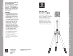
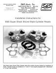
S&S Cycle, Inc
®
Instruction 51-1026
06-01-10
Copyright © 2002, 2003, 2005,
2006, & 2010
by S&S® Cycle, Inc.
.
14025 Cty Hwy G PO Box 215
Viola, Wisconsin 54664
Phone: 608-627-1497 • Fax: 608-627-1488
Technical Service Phone: 608-627-TECH (8324)
Technical Service Email: [email protected]
Website: www.sscycle.com
All rights reserved.
Printed in the U.S.A.
Installation Instructions for S&S®Cams for
Panhead, Shovelhead, & Harley-Davidson® Evolution® Engines
DISCLAIMER:
S&S parts are designed for high performance, closed course, racing
applications and are intended for the very experienced rider only. The
installation of S&S parts may void or adversely affect your factory warranty.
In addition such installation and use may violate certain federal, state, and
local laws, rules and ordinances as well as other laws when used on motor
vehicles used on public highways, especially in states where pollution laws
may apply. Always check federal, state, and local laws before modifying your
motorcycle. It is the sole and exclusive responsibility of the user to determine
the suitability of the product for his or her use, and the user shall assume all
legal, personal injury risk and liability and all other obligations, duties, and
risks associated therewith.
The words Harley®, Harley-Davidson®, H-D®, Sportster®, Evolution®, and all
H-D part numbers and model designations are used in reference only. S&S
Cycle is not associated with Harley-Davidson, Inc.
SAFE INSTALLATION AND OPERATION RULES:
Before installing your new S&S part it is your responsibility to read and follow
the installation and maintenance procedures in these instructions and follow
the basic rules below for your personal safety.
Gasoline is extremely flammable and explosive under certain conditions
and toxic when breathed. Do not smoke. Perform installation in a well
ventilated area away from open flames or sparks.
If motorcycle has been running, wait until engine and exhaust pipes
have cooled down to avoid getting burned before performing any
installation steps.
Before performing any installation steps disconnect battery to eliminate
potential sparks and inadvertent engagement of starter while working
on electrical components.
Read instructions thoroughly and carefully so all procedures are
completely understood before performing any installation steps.
Contact S&S with any questions you may have if any steps are unclear or
any abnormalities occur during installation or operation of motorcycle
with a S&S part on it.
Consult an appropriate service manual for your motorcycle for correct
disassembly and reassembly procedures for any parts that need to be
removed to facilitate installation.
Use good judgment when performing installation and operating
motorcycle. Good judgment begins with a clear head. Don’t let
alcohol, drugs or fatigue impair your judgment. Start installation
when you are fresh.
Be sure all federal, state and local laws are obeyed with the installation.
For optimum performance and safety and to minimize potential
damage to carb or other components, use all mounting hardware that is
provided and follow all installation instructions.
Motorcycle exhaust fumes are toxic and poisonous and must not be
breathed. Run motorcycle in a well ventilated area where fumes can
dissipate.
••
••
••
••
••
••
••
••
••
IMPORTANT NOTICE:
Statements in this instruction sheet preceded by the following words are of
special significance.
WARNING
Means there is the possibility of injury to yourself or others.
CAUTION
Means there is the possibility of damage to the part or motorcycle.
NOTE
Other information of particular importance has been placed in italic type.
S&S recommends you take special notice of these items.
WARRANTY:
All S&S parts are guaranteed to the original purchaser to be free of
manufacturing defects in materials and workmanship for a period of twelve
(12) months from the date of purchase. Merchandise that fails to conform to
these conditions will be repaired or replaced at S&S’s option if the parts are
returned to us by the purchaser within the 12 month warranty period or within
10 days thereafter.
In the event warranty service is required, the original purchaser must call or
write S&S immediately with the problem. Some problems can be rectified by
a telephone call and need no further course of action.
A part that is suspect of being defective must not be replaced by a Dealer
without prior authorization from S&S. If it is deemed necessary for S&S to
make an evaluation to determine whether the part was defective, a return
authorization number must be obtained from S&S. The parts must be packaged
properly so as to not cause further damage and be returned prepaid to S&S
with a copy of the original invoice of purchase and a detailed letter outlining
the nature of the problem, how the part was used and the circumstances at
the time of failure. If after an evaluation has been made by S&S and the part
was found to be defective, repair, replacement or refund will be granted.
ADDITIONAL WARRANTY PROVISIONS:
(1) S&S shall have no obligation in the event an S&S part is modified by any
other person or organization.
(2) S&S shall have no obligation if an S&S part becomes defective in whole or in
part as a result of improper installation, improper maintenance, improper use,
abnormal operation, or any other misuse or mistreatment of the S&S part.
(3) S&S shall not be liable for any consequential or incidental damages
resulting from the failure of an S&S part, the breach of any warranties, the
failure to deliver, delay in delivery, delivery in non-conforming condition, or
for any other breach of contract or duty between S&S and a customer.
(4) S&S parts are designed exclusively for use in Harley-Davidson® and other
American v-twin motorcycles. S&S shall have no warranty or liability obligation
if an S&S part is used in any other application.
PANHEAD & SHOVELHEAD CAMS
VALVE TIMING †
VALVE
DURATION
VALVE LIFT
LIFT @ TDC ‡
REQUIREMENTS
Part
#
Cam
Name
Recommended
Application
Intake
Open/Close
Exhaust
Open/Close
Intake
Exhaust
Shovel
Pan
Intake
Exhaust
Spring
Spacing
Tappet
Type
33-5062
S&S
450S
1948-’69
Up to 8.5:1
18°/38°
40°/18°
236°
38°
.453"
.475"
.151" Shovel
.158" Pan
.145" Pan
152" Pan
No
Hydraulic
33-5063
S&S
450S
1970-’77
Up to 8.5:1
18°/38°
40°/18°
236°
238°
.453"
.475"
.151" Shovel
.158" Pan
.145" Pan
.152" Pan
No
Hydraulic
33-5064
S&S
450S
1978-’84
Up to 8.5:1
18°/38°
40°/18°
236°
238°
.453"
.475"
.151" Shovel
.158" Pan
.145" Pan
152" Pan
No
Hydraulic
33-5040
S&S
495
1948-’69
9.75 or Higher
30°/62°
62°/30°
274°
274°
.495"
.520"
.220"
.198"
Yes
Solid
33-5041
S&S
495
970-’77
9.75 or Higher
30°/62°
62°/30°
274°
274°
.495"
.220"
.198"
Yes
Solid
33-5042
S&S
495
1978-’84
9.75 or Higher
30°/62°
62°/30°
274°
274°
.495"
.220"
.198"
Yes
Solid
33-5050
S&S
514
1948-’69
8:1 to 9:1
23°/43°
43°/23°
246°
246°
.514"
.194"
.186"
Yes
Solid
33-5051
S&S
514
1970-’77
8:1 to 9:1
23°/43°
43°/23°
246°
246°
.514"
.194"
.186"
Yes
Solid
33-5052
S&S
514
1978-’84
8:1 to 9:1
23°/43°
43°/23°
246°
246°
.514"
.194"
.186"
Yes
Solid
33-5059
S&S
560S
1948-’69
9:1 to 10:1
20°/55°
60°/20°
255°
260°
.560"
.168"
164"
Yes
Solid
33-5060
S&S
560S
1970-Early ‘77
9:1 to 10:1
20°/55°
60°/20°
255°
260°
.560"
.168"
164"
Yes
Solid
33-5061
S&S
560S
1977-Early ‘84
9:1 to 10:1
20°/55°
60°/20°
255°
260°
.560"
.168"
.164"
Yes
Solid
.540"
.587"
† Timing designation is function of zero lash @ .053" off base circle.
NOTE: Cams can be used in other applications. Call S&S for information if you have any questions.
‡ TDC Lifts are measured at the valve and are for reference only. Overlap valve lifts must be checked on assembled motor. Minimum valve to
valve clearance is .040".
2
CAMS for 1984-1999 BIG TWINS
VALVE TIMING †
VALVE DURATION
LIFT @ TDC ‡
REQUIREMENTS
Part
#
Cam
Name
Recommended
Application
Intake
Open/Close
Exhaust
Open/Close
Intake
Exhaust
Intake
Exhaust
Spring
Spacing
Tappet
Type
33-5075
Bolt-In
S&S
502
Stock 80" to 89"
8.5:1 to 9.5:1
28°/40°
50°/24°
248°
254°
.225"
.221"
No
Hydraulic
33-5073
S&S
520
Engines to 96"
8.5:1 to 10:1
0°/40°
50°/2°
220°
232°
.086"
.094"
Yes
Hydraulic
33-5072
S&S
546
4" Bore Engines
9:1 to 10:1
5°/55°
52°/5°
240°
237°
.126"
.106"
Yes
Hydraulic
33-5076
S&S
561
80" to 100"
9:1 to 10:1
32°/40°
50°/26°
252°
256°
.252"
.210"
Yes
Hydraulic
33-5079
S&S
562
98" to 113"
10:1 to 10.5:1
34°/55°
60°/29°
269°
269°
.260"
.220"
Yes
Hydraulic
33-5057
S&S
563
1984-Present
10.5:1 or Higher
32°/64°
64°/32°
276°
276°
.250"
.220"
Yes
Solid or
Hydraulic
33-5109
S&S
585V
1984-Present
9.5:1 to 10.5:1
20°/45°
60°/20°
245°
260°
.186"
.180"
Yes
Hydraulic
33-5058
S&S
600
4" Bore Engines
9.5:1 to 10.5:1
20°/55°
60°/20°
255°
260°
.218"
.198"
Yes
Hydraulic
33-5080
S&S
631
1984-Present
10.5:1 or Higher
34°/61°
66°/29°
275°
276°
.281"
.221"
Yes
Solid or
Hydraulic
33-5108
S&S
640
1984-Present
10.5:1 to 11.5:1
25°/60°
65°/20°
265°
265°
.222"
.192"
Yes
Hydraulic
33-5133
S&S
675*
1984-Present
10.5:1 to 11.5:1
25°/64°
70°/25°
269°
275°
.235"
.209"
Yes
Hydraulic
* Race application, verify all clearances.
† Timing designation is function of zero lash @ .053" off base circle.
‡ TDC Lifts are measured at the valve and are for reference only. Overlap valve lifts must be checked on assembled motor. Minimum valve to
valve clearance is .040".
3
GENERAL INFORMATION
1. Lifters
A.Camshafts with lifts greater than stock generally have lobes that are taller than stock which means that the cam followers or lifters will travel
a greater distance. For this reason it is necessary to check clearance between the lifter roller and tappet block, and between the rear cam
bearing and pinion bearing race.
B.High performance Harley-Davidson® Evolution® engines equipped with hydraulic lifters can often benefit from using an S&S® HL2T Hydraulic
Lifter Limited Travel Kit. In many instances, the HL2T kit will help lower cranking compression for easier starting. Additionally, these simple,
low cost kits reduce the likelihood of lifter collapse at high rpm. Kit part number for 1984-1985 Evolution® models with stock lifters and all
engines with S&S 33-5342 lifters introduced in late 1998 is 33-5338. Kit 33-5339 fits 1986-up Evolution® lifters and older S&S lifters 33-5340
and 33-5341.
2. Pushrods
A.Most high performance camshaft installations require the installation of a solid lifter conversion kit or adjustable pushrods. Adjustable
pushrods give the flexibility required to compensate for any differences in cam base circle dimensions, gasket thickness, and cylinder head
modifications. If pushrods are changed, depending upon their design, it may be necessary to do some additional pushrod-to-pushrod
tube and pushrod-to-cylinder head clearancing. This clearancing is necessary because the pushrod angle from the lifter to the rocker arm
changes due to additional lift of the camshaft. All S&S pushrods with tubing diameters of 7⁄16" or less can be used with any S&S cam without
additional clearancing. It is recommended that these clearances be checked if another pushrod type is used. Consult the pushrod installation
instructions. S&S makes adjustable chrome-moly steel pushrod kits for all big twin applications.
3. Rocker Arms
A.Additional camshaft lift causes additional rocker arm travel. Older engines should be checked to see if the rocker arm ends that contact the
valve are irregular or worn excessively. If they appear serviceable, they should then be checked to see how they contact the end of the valve
during a complete opening and closing cycle. The extra travel of the valve caused by a high lift cam may cause the rocker arm to contact the
valve improperly at the full open position. If irregular contact due to excessive wear is present, the rocker arm should be replaced.
B.Additional rocker arm travel may reduce the existing clearance between the rocker arm and rocker cover and between the rocker arms and
the top valve spring collar. This is of particular concern in instances where the valves have receded deep in the head due to worn valve seats.
Both clearances must be checked and corrected before final assembly. Machinist’s blue or putty can be used to check for contact.
NOTE: S&S recommends the use of roller rockers in high-lift applications to reduce valve stem and guide wear caused by elevated side-loads. Some degree
of side loading occurs with all lifts. The greater the lift, the greater the amount of side-load.
4. Valve Springs
A.Valve springs and top spring collars travel farther with a high lift cam. They must be spaced to prevent the spring from coil binding and
to prevent the top collar from contacting the valve guides. With valve fully open there must be a minimum of .060" additional valve travel
available before any coils of the inner or outer valve springs contact each other. A minimum clearance of .060" must be maintained between
the top valve spring retainer and the valve guide or valve seal when the valve is completely open.
B.The machining process required to prevent coil bind and maintain adequate seat pressures with stock springs can be difficult and expensive.
S&S recommends our .630" lift high performance spring kit 93-2077 (steel collars) or 93-2078 (titanium top collars) for most Evolution®
engines. Kits for higher lifts are also available. S&S offers several high-lift spring kits for shovelheads and panheads. The .550" lift kit 90-2053
(aluminum collars) fits 1948-early 1984 panheads and shovelheads. The .590" lift kit 90-2060 (steel collars) fits 1948-early 1981 panheads and
shovelheads. The 90-2063 kit fits late 1981-1984 shovelheads.
NOTE: S&S also offers panhead and shovelhead kits with titanium top collars. Shortening of the valve guide may be required. Otherwise, these kits virtually
eliminate the need for machining.
C.Because of its .560" lift, an experienced engine builder should install our 560S cam for shovelheads. The installation can be simplified by
using one of the .590" lift valve spring kits mentioned in the preceding paragraph. Moderate TDC lifts mean that, in most existing highperformance applications, no additional valve-to-piston or valve-to-valve clearancing will be required. Shortening of the valve guide for
adequate top collar-to-guide clearance may be required.
5. Valves and Pistons
A.A high performance camshaft increases the breathing capabilities of the engine by increasing the valve lift and/or duration. Valves that
open higher for longer periods of time run a greater risk of contacting each other or the pistons. If larger than stock diameter valves are used,
valve clearance problems are even more apt to occur.
B.S&S® recommends a minimum of .040" clearance between the valves throughout their opening and closing cycles. This can be checked with
a .040" diameter wire inserted through the spark plug hole.
C.Absolute minimum valve clearance between valves and pistons is .060" for the intakes and .080" for exhausts.
NOTE: Due to the increased lift and duration installation of most high performance camshafts require that valve train clearances be checked and corrected
if needed. Consult cam specifications on first page to determine which checks must be performed.
4
CAUTION
Failure to follow instructions and perform any required clearancing procedures may result in insufficient clearances between valve train
parts and other engine components causing damage to engine.
6. Other Information
A.All S&S cams are ground to fit needle roller style crankcase cam bearings. If an S&S cam is installed in an early set of big twin crankcases with
a bushing style cam bearing, then the bushing must be reamed to fit the bearing diameter of the camshaft.
B.In all 1948 to early 1984 installations where solid lifter style tappets are used S&S recommends plugging the hydraulic lifter oil feed holes
in the tappet blocks. If this procedure is not performed, excessive oil can bleed off the cam followers and fill the pushrod tubes causing
leakage. To perform this modification thread an 8-32 tap into the oil passage hole in the gasket surface and turn the tap until it just starts to
enter the cam follower hole. Then, screw an 8-32 x 3⁄16" allen head set screw in place to block the hole.
NOTE: If hydraulic lifters are ever reinstalled, these screw plugs must be removed.
7. Cam Gear Measuring
A.Start by installing .105" pins 180° apart on the cam gear—a rubberband will help hold them in one place.
B. Use a micrometer to measure the assembly and make a note of the dimension. Transfer the pins to the pinion gear and measure it also.
C. Match the pinion gear to the size closest to it in the chart below. The closer the sizing the less noise you will encounter.
D.Install the pinion and cam dry, use a new gasket and torque the cam cover in place. Verify in four different spots that the cam slides easily
and consistently across the pinion gear and check backlash at the same time.
E. Once you have verified that the fit is proper lubricate everything and move on to final assembly.
GEAR DIAMETER CHART
Color
Pinion Gear Diameter over .105" Pins
Cam Gear Diameter Over .105" Pins
Orange
1.4751-1.4756
2.7324-2.7334
White
1.4745-1.4751
2.7334-2.7344
Yellow
1.4737-1.4745
2.7344-2.7354
Red
1.4729-1.4737
2.7354-2.7364
Blue
1.4721-1.4729
2.7364-2.7374
Green
1.4715-1.4721
2.7374-2.7384
Black
1.4710-1.4715
2.7384-2.7394
8. Camshaft Installation Procedure
A.Remove pushrods. Pushrods can be removed from panheads and shovelheads by setting adjusters to shortest adjustment. It is necessary to
remove the rocker cover and rocker arm for pushrod removal and installation in a Evolution® engine.
B.Remove stock camshaft. Measure length of stock camshaft and new camshaft. If lengths are not equal (should be close to 3.025") change
spacer shims to make up any difference. Shovelhead and Evolution® engines use same shims. Camshafts for 1988 and later Evolution®
engines need to be shimmed to 3.075" (+.050" longer) because of a factory design change. Many engine builders replace inner camshaft
bearing when installing cam. Refer to Harley-Davidson® service manual for correct procedure.
NOTE: S&S recommends that when installing high performance cams in 1992 and later big twin engines, the inner camshaft bearing (marked INA SCE 138
USA), should be replaced with a Torrington B138 bearing (AP part #292310, S&S part 31-4009). The Torrington bearing has a higher radial load rating and is
better able to handle increased stress of high performance cams.
CAUTION
Use of the stock 1992 and later inner camshaft bearing with high performance camshaft may result in bearing failure, and cause serious
engine damage.
C.Install new cam and check for proper endplay. Endplay for installed camshafts should be .005" to .015".
D.Install lifters and pushrods. The longest pushrod is for front exhaust, next longest pushrod is for rear exhaust, and two shortest pushrods are
for front and rear intakes.
E.Adjust pushrods - In all cases engine must be cold and lifter to be adjusted must be at lowest position for pushrod adjustment.
1. Solid lifters. (All Engines)
a. Turn adjusting screw until free play is removed, and pushrod can be turned between thumb and forefinger with some drag.
b. Tighten locking nut, and recheck pushrod adjustment to insure that adjustment is still correct.
c. Rotate engine to place next pushrod at lowest point on cam and repeat procedure. Repeat for remaining pushrods.
5
2. Hydraulic lifters.
a. Turn adjusting screw until pushrod contacts lifter and all free play is removed.
b.Turn adjusting screw an additional 4 to 41⁄2 turns (24-27 flats), and tighten locknut. Allow sufficient time for lifter to bleed down.
Pushrod will spin freely after lifter bleeds down. It is imperative that engine not be rotated until lifter spins freely.
c. Rotate engine to place next pushrod at lowest point on cam and repeat procedure. Repeat for remaining pushrods.
3. Harley-Davidson® Evolution® hydraulic lifters with S&S® HL2T Limited Travel Kit. (Adjustable pushrods must be used with HL2T Kit.)
a. Lengthen pushrod adjuster 20 flats to fully collapse lifter. Pushrod will be extremely difficult to turn by hand.
NOTE: It may take as long as twenty minutes for lifter to fully collapse. Wait 20 minutes and attempt to rotate pushrod by hand. If pushrod cannot be
rotated with moderate effort, proceed to Step B. If pushrod can be rotated, extend adjuster 10 additional flats, wait 20 minutes and attempt to rotate
pushrod again. Do not proceed until pushrod cannot be rotated after 20 minutes.
b.After lifter is fully collapsed, shorten adjuster exactly to point where pushrod can be rolled between thumb and forefinger with
minimum effort.
NOTE: Some lifters with HL2T Kit provide quieter operation if pushrod adjuster is shortened 3 to 6 additional flats from point where pushrod can just be
turned by hand. The additional travel that results may improve the ability of the hydraulic unit to fill with oil and operate at zero lash.
c. Tighten locking nut against pushrod and confirm that pushrod adjustment remains correct.
d. Rotate engine to place next pushrod at lowest point on cam and repeat procedure. Repeat for remaining pushrods.
NOTE: If hydraulic units contain oil allow sufficient time for lifter to bleed down before final adjustment is made.
CAUTION
Do not turn engine until lifter is fully bled down and adjustment has been made. Valves could contact each other and cause damage.
9. Valve Spring Installation Information
A.Installation of an S&S® high lift racing valve spring kit may require that the spring pocket of the head be machined to the proper diameter.
Lower valve spring collar should seat completely flat on cylinder head surface and lower coils of valve spring should not touch sides of
spring pocket.
B.Heads must be removed to check the installed spring height. This is the distance from the bottom of the top retainer to the top surface
of the lower valve spring collar where the spring rests on the head (Dimension A, Figure 1). This distance is the height of the outer valve
spring when the valve is on the seat (typically 1.490" to 1.520" for panheads and shovelheads and 1.800" for Evolutions). Install the valve in
the guide. Then install the bottom collar, top retainer and keepers. Pull the top retainer tightly against the keepers. While holding the valve
assembly steady, measure the distance between the lower valve spring seating surface and the outside step of the top retainer. Record your
information.
After you have measured all the valves, find the shortest height. This will become the installed height for all the valve springs.
C.Once you have determined the installed height, use shims to obtain the same installed height for all valve springs (+.020" is acceptable).
Extra shims are available through S&S, if needed.
D.Before removing the retainers, measure the distance from the bottom of the retainer to the top of the valve guide or valve seal. (Dimension
B, Figure 1). This distance must be .060" greater than the lift of the valve. If not, the guide must be shortened to obtain clearance. Insufficient
clearance between top collar and valve seal is a very common cause of early camshaft fatigue and valve seal failure.
B
A
Remove seal and grind
guide here to obtain
greater measurement B.
6
EOnce the valve springs have been installed it is important to check for coil bind. With valve fully open, there must be a minimum of .060"
additional valve travel available before either the inner or outer valve springs are coil bound solid. If this clearance does not exist, the valves
must be sunk deeper in the head by grinding the valve seats. The typical installed valve spring height of 1.520" for panhead engines and
shovelhead engines, and 1.800" for Evolution® models should not be increased by more than .040".
F.Always check for clearance between the valve spring retainer and the inside face of the rocker arm. This is most critical when the valve is
fully closed. Rocker arms are designed to clear specific spring diameters so it is important that the proper rocker arm/retainer combination
is used. Insufficient clearance can also be the result of improper rocker arm geometry and/or incorrect valve stem length.
7
8