1
Section 1 – Principle of Operation
These meters are of the rotary positive displacement
type. The accurately-machined housing contains a rotor which revolves on ball bearings and carries evenlyspaced blades. As liquid flows through the meter, the
rotor and blades (vanes) revolve about a fixed cam
causing the blades to move outward. The successive
movement of the blades forms a measuring chamber of
precise volume between two of the blades, the rotor, the
housing, the bottom, and the top covers. A continuous
series of these closed chambers is produced for each
rotor revolution. Neither blades nor rotor contact the
stationary walls of the measuring chamber.
One of the outstanding features of the Smith meter
principle is that the flow is literally undisturbed while it
is being metered. Energy is not wasted by unnecessary
hydraulic bending of the liquid.
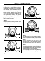
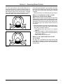
Figure 3
Figure 1
Unmeasured liquid (shaded area) is shown entering
meter. Rotor and vanes are turning clockwise. Vanes A
and D are fully extended forming the measuring chamber; Vanes B and C are retracted.
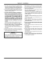
Figure 4
Figure 1
Figure 2
The rotor and vanes have made one-eighth revolution.
Vane A is fully extended; Vane B is partially extended;
Vane C is fully retracted; Vane D is partially retracted.
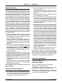
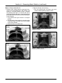
Figure 3
A quarter revolution has been made. Vane A is still
extended and Vane B is now fully extended. An exact
and known volume of new liquid is now in the measuring chamber.
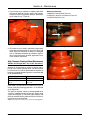
Figure 4
One eighth revolution later, the measured liquid is moving out of the meter. A second measuring chamber is being created between Vanes B and C. Vane A has begun
to retract and Vane C is beginning to extend.
In three-eighths of a revolution, one measured segment
of fluid has been passed and a second segment is being
created. This cycle is repeated as long as liquid flows.
Figure 2
Page 2 • MN01011
Issue/Rev. 0.9 (7/11)