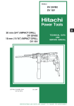
1
MODEL
SP 18VA
POWER TOOLS
ELECTRONIC SANDER POLISHER
SP 18VA
TECHNICAL DATA
AND
SERVICE MANUAL
S
LIST No. 0352
Jun. 2002
SPECIFICATIONS AND PARTS ARE SUBJECT TO CHANGE FOR IMPROVEMENT
REMARK:
Throughout this TECHNICAL DATA AND SERVICE MANUAL, a symbol(s)
is(are) used in the place of company name(s) and model name(s) of our
competitor(s). The symbol(s) utilized here is(are) as follows:
Competitor
Symbol Utilized
C
Company Name
Model Name
MAKITA
9227C/9227CB
CONTENTS
Page
1. PRODUCT NAME ........................................................................................................................... 1
2. MARKETING OBJECTIVE ............................................................................................................. 1
3. APPLICATIONS .............................................................................................................................. 1
4. SELLING POINTS .......................................................................................................................... 1
4-1. Selling Point Descriptions ............................................................................................................... 2
5. SPECIFICATIONS .......................................................................................................................... 3
6. COMPARISONS WITH SIMILAR PRODUCTS .............................................................................. 4
6-1. Specification Comparisons ............................................................................................................. 4
6-2. Practical Test Data .......................................................................................................................... 5
7. PRECAUTIONS IN SALES PROMOTION ..................................................................................... 6
7-1. Handling Instructions ...................................................................................................................... 6
7-2. Caution on Name Plate ................................................................................................................... 6
7-3. Precautions on Usage .................................................................................................................... 6
8. FUNCTION AND OPERATION OF THE CONTROL CIRCUIT ...................................................... 7
8-1. Control Circuit (Block Diagram) ...................................................................................................... 7
8-2. Function of Each Block ................................................................................................................... 7
8-3. Motor Characteristics and Voltage Applied to the Motor ................................................................. 8
9. PRECAUTIONS IN DISASSEMBLY AND REASSEMBLY ............................................................ 9
9-1. Disassembly of the Armature Ass'y ................................................................................................. 9
9-2. Disassembly of the Stator Ass'y .................................................................................................... 10
9-3. Disassembly of the Gear .............................................................................................................. 10
9-4. Reassembly ................................................................................................................................... 11
9-5. Tightening Torque .......................................................................................................................... 11
9-6. Wiring Diagram .............................................................................................................................. 11
9-7. Insulation Tests ............................................................................................................................. 12
9-8. Gear Backlash Value ................................................................................................................... 12
9-9. No-Load Current Value ................................................................................................................. 12
10. STANDARD REPAIR TIME (UNIT) SCHEDULES ..................................................................... 13
Assembly Diagram for SP 18VA
1. PRODUCT NAME
Hitachi Electronic Sander Polisher, Model SP 18VA [180 mm (7")]
2. MARKETING OBJECTIVE
The Model SP 18VA has been developed to upgrade and replace the current Model SP 18V. The main
improvements are increased motor power, weight reduction and improved operability.
3. APPLICATIONS
Sanding metallic surfaces.
Preparatory sanding and removing rust from metallic surfaces prior to painting, and removing paint prior to
repainting.
Finishing woodwork and making flush joints of wooden plates.
Preparatory sanding wooden surfaces prior to painting.
Finishing and polishing painted metallic surfaces of motor vehicles, rolling stocks, elevators, refrigerators,
sewing machines, washing machines, medical instruments, and so on.
Polishing lacquered surfaces on wooden products such as furniture.
Polishing synthetic resin and ebonite products.
4. SELLING POINTS
High-power motor,
max. output 2,200 W (2.9 HP)
Maker C's model: 1,900 W (2.5 HP)
Loop handle
Variable trigger switch
Equipped with electronic control devices
Constant speed control
Soft start speed control
Variable speed control
Lightweight: 2.8 kg (6.2 lbs.)
Maker C's model: 3.0 kg (6.6 lbs.)
Iron bearing bushing improves heat
resistance of the bearing chamber on
the commutator side.
Compact body: 415 mm (10-19/36")
Maker C's model: 423 mm (10-3/4")
--- 1 ---
4-1. Selling Point Descriptions
1) High-power motor and light weight
The Model SP 18VA is equipped with high-power motor and is more powerful than the current Model SP 18V
although it is compact and lightweight. We could say that the ratio of the motor's maximum output to the
product's weight defines its performance. Compared with a typical competitor's model in terms of this
indicator, the Model SP 18VA proves to have the highest performance.
Table 1 Comparison of max. output and product weight
Maker
Model
Item
Hitachi
SP 18VA
C
SP 18V
Max output *1
(W)
2,560 (3.4 HP)
1,700 (2.3 HP)
1,900 (2.5 HP)
Actual product weight *2
(kg)
2.8 (6.2 lbs.)
3.0 (6.6 lbs.)
3.0 (6.6 lbs.)
914 (0.55 HP/lbs.)
567 (0.35 HP/lbs.)
633 (0.38 HP/lbs.)
Max output/product weight
*1
*2
(W/kg)
Max. output may vary depending on the market.
Actual product weight is a measured weight and excludes cord, loop handle, rubber pad and washer nut.
2) Iron bearing bushing
An iron bearing bushing is newly added to the housing. The heat resistance of the bearing chamber on the
commutator side is significantly improved in comparison with current models.
New ball bearing chamber
of housing (SP 18VA)
Current ball bearing chamber
of housing (SP 18V)
Rubber ring
Ball bearing
Ball bearing
Bearing bushing (iron)
Ball bearing chamber of housing
Ball bearing chamber of housing
Fig. 2
--- 2 ---
5. SPECIFICATIONS
Model
SP 18VA
Item
Capacity disc dia.
180 mm (7")
Power source
AC single phase 50 or 60 Hz
Voltage (V) Current (A)
Voltage, current and input
110
12.0
120
11.0
220
6.0
230
5.7
240
5.5
Input (W)
1,250
Rotation speed (no-load)
0 to 600/3,400 /min
Type of motor
AC single-phase commutator motor
Type of switch
Trigger switch
Material: Housing
Glassfiber reinforced polyamide resin (green)
Handle
Glassfiber reinforced polyamide resin (black)
Gear cover
Aluminum alloy die casting
Packing gland
Coating: Gear cover
Metallic silver
Packing gland
• • • • •
• • • • •
Enclosure
•••••
• • • • •
Net*
2.8 kg (6.2 lbs.)
Gross
5.5 kg (12.2 lbs.)
Weight
Packaging
Corrugated cardboard box
Standard accessories
Rubber pad
Loop handle
Wrench
•••••• • • • • • • • • • • • • • • • • • • • • • • • • • • • • • • • • • • • • • • • • • • • • • • • • • • • • • • • • • • • • • • • • • • • • • • • • • • • • • • • • • • • • • • • • • • • • • • •
••••• • • • • • • • • • • • • • • • • • • • • • • • • • • • • • • • • • • • • • • • • • • • • • • • • • • • • • • • • • • • • • • • • • • • • • • • • • • • • • • • • • • • • • • • • • • • • • • • •
•••••••••••• • • • • • • • • • • • • • • • • • • • • • • • • • • • • • • • • • • • • • • • • • • • • • • • • • • • • • • • • • • • • • • • • • • • • • • • • • • • • • • • • • • • • • • • • • • • • • • • •
* Weight excludes cord, loop handle, rubber pad and washer nut.
Relationship between dial settings and rotation speeds of the Model SP 18VA
4,000
3,000
2,000
1,000
1
2
3
4 5
Dial
--- 3 ---
6
1
1
1
6. COMPARISONS WITH SIMILAR PRODUCTS
6-1. Specification Comparisons
Maker
HITACHI
Model
Capacity disc dia.
mm
C
SP 18VA
SP 18V
180 (7")
180 (7")
180 (7")
1,100
1,200
Input
W
1,250
Output*1
W
680
407
555
Max. output*1
W
2,560
1,700
1,900
/min.
0 --- 600/3,400
1,400 --- 3,400
0 --- 600/3,000
Dial and trigger switch
Dial
Dial and trigger switch
None
Equipped
None
84
86
83
Spindle lock
Equipped
Equipped
Equipped
Handle type
Loop handle
Side handle
Loop handle
Rotation speed (no-load)
Variable speed control
Overload protection control
No-load sound pressure level dB/A
Weight*2
Dimensions
Catalog
kg
2.8 (6.2 lbs.)
3.0 (6.6 lbs.)
3.0 (6.6 lbs.)
Actual
kg
2.8 (6.2 lbs.)
3.0 (6.6 lbs.)
3.0 (6.6 lbs.)
H
mm
126 (3-7/36")
128 (3-1/4")
134 (3-5/12")
h
mm
81 (2-1/18")
82 (2-1/12")
88 (2-2/9")
L
mm
415 (10-19/36")
417 (10-7/12")
423 (10-3/4")
*1 Output may vary depending on the market.
*2 Weight excludes cord, loop handle, rubber
L
pad and washer nut.
H
h
--- 4 ---
6-2. Practical Test Data
1) Comparisons in torque vs. rotation speed
Rotation speed of spindle (1/min.)
3500
SP 18VA (maximum speed)
3000
SP 18V (maximum speed)
2500
C (maximum speed)
2000
SP 18V (minimum speed)
1500
1000
SP 18VA (minimum speed)
500
C (minimum speed)
0
1
2
3
4
5
Torque (N•m)
2) Sanding performance comparisons
Workpiece material: SPCC (mild steel)
Sanding disc used: AP #50
Applied pressure: 4 kg
Speed: Maximum speed
350
SP 18VA
Sanding dust produced (g)
300
250
C
200
150
SP 18V
100
50
0
5
10
--- 5 ---
15
Time (min.)
7. PRECAUTIONS IN SALES PROMOTION
In the interest of promoting the safest and most efficient use of the Model SP 18V Electronic Sander Polisher by
all of our customers, it is very important that at the time of sale the salesperson carefully ensures that the buyer
seriously recognizes the importance of the contents of the Handling Instructions, and fully understands the
meaning of the precautions listed on the Caution Plate attached to each tool.
7-1. Handling Instructions
Although every effort is made in each step of design, manufacture and inspection to provide protection against
safety hazards, the dangers inherent in the use of any electric tool cannot be completely eliminated. Accordingly,
general precautions and suggestions for the use of electric power tools, and specific precautions and suggestions
for the use of the Electronic Sander Polisher are listed in the Handling Instructions to enhance the safe and
efficient use of the tool by the customer. Salespersons must be thoroughly familiar with the contents of the
Handling Instructions to be able to offer appropriate guidance to the customer during sales promotion.
7-2. Caution on Name Plate
Each tool is provided with a Name Plate which contains the following basic safety precautions in the use of the
tool.
(1) For Australia, New Zealand and China
(2) For U.S.A. and Canada
(3) For Switzerland, U.K., Germany, Belgium, France, Netherlands, Austria, Spain,
Italy, Finland, Denmark and Norway
7-3. Precautions on Usage
Never press the pushing button while the spindle is rotating:
If the pushing button is pressed while the spindle is rotating, the spindle will stop immediately. In such a case,
there is a danger that the washer nut may be loosened so that the rubber pad and wool bonnet fly off
unexpectedly to cause possible serious injury.
--- 6 ---
8. FUNCTION AND OPERATION OF THE CONTROL CIRCUIT
8-1. Control Circuit (Block Diagram)
Switch
Motor
AC power source
Triac
Rotation speed
detector
Standard voltage
circuit
F-V converter
Phase control circuit
Variable resistor
Ramp generator
Differential
amplifier
Soft start and constant speed control circuit
Load current detecting circuit
Load current control circuit
8-2. Function of Each Block
(1) Rotation speed detector:
Generates a frequency signal proportionate to the actual rotation speed of the motor. A magnetic sensor in the
controller monitors changes in the magnetic flux from a magnet, and generates a frequency signal.
(2) F-V converter:
Converts the frequency signal produced by the rotation speed detector into DC voltage.
(3) Standard voltage circuit:
Generates a standard voltage which determines the no-load rotation speed of the motor and serves as a
reference in maintaining constant rotation speed even when there are fluctuations in the load.
(4) Ramp generator:
Generates the voltage which determines the acceleration of the motor. The soft start function when the motor
is turned on is achieved through a gradual increase of the voltage generated by this circuit. When fully
charged, the voltage of the ramp generator becomes equal to the standard voltage (above).
(5) Differential amplifier:
Compares the voltage from the ramp generator voltages received from the F-V converter (which is
proportionate to the actual motor rotation speed), and amplifies the result.
This circuit functions as follows to maintain a constant rotation speed:
Motor rotation speed decreases (or increases)
(or increases)
frequency signal decreases
output voltage of the F-V converter decreases (or increases)
output voltage of the differential amplifier increases (or decreases).
--- 7 ---
(6) Load current detecting circuit:
Detects the load current by means of a low resistance resistor which is in series with the motor and the triac.
(7) Load current control circuit:
When the detected load is excessive (overload), this circuit sends a command (control signal) to reduce power
to the motor.
(8) Phase control circuit:
Generates the trigger signals necessary to turn the triac on, and delivers them to the gate of the triac. The
conductive angle of the triac is determined by the timing of the generated trigger signals.
When starting the tool: Controlled by the soft start circuit, the phase control circuit generates trigger signals
to gradually increase the conductive angle of the triac.
Constant speed operation: When there are variations in the rotation speed, the phase control circuit
generates trigger signals to keep the rotation speed as close as possible to the
present rotation speed determined by the standard voltage circuit. In short, when
the load increases and causes the rotation speed to decrease, the conductive
angle of the triac is increases, and the voltage applied to the motor is increased.
In this way, the rotation speed is kept as close as possible to the standard
rotation speed.
8-3. Motor Characteristics and Voltage Applied to the Motor
Conductive
angle
Rotation speed
Rotation speed
determined by
the standard
voltage circuit
Rotation speed
Phase control voltage waveform
(When electronic control
not applied)
Dial
6
Soft start characteristics
when starting the tool
Voltage applied to
the motor increases
gradually
Switch ON
Dial
As the load inceases,
the voltage applied to the
motor increases.
Dial
0 No-load
Load
--- 8 ---
Time
9. PRECAUTIONS IN DISASSEMBLY AND REASSEMBLY
The [Bold] numbers in the descriptions below correspond to the item numbers in the Parts List and exploded
assembly diagram for the Model SP 18VA.
9-1. Disassembly of the Armature Ass'y
(1) Loosen the two Brush Caps [45], and take out the Carbon Brushes [46].
(2) Remove the four Tapping Screws (W/Flange) D5 x 30 [2]. The Armature Ass'y [13] can then be taken out
simultaneously with the Gear Cover Ass'y [5], Packing Gland [30] and related parts.
(3) Remove the four Seal Lock Screws (W/Sp. Washer) M5 x 14 (Black) [31], and remove the Packing Gland [30],
and related parts.
(4) After removing the three Seal Lock Screws (W/Sp. Washer) M4 x 10 [1], the Armature Ass'y [13] can be
extracted together with the Bearing Cover (B) [12], and related parts.
(5) Carefully wrap the Armature Ass'y [13] with a soft, clean rag to protect it from being damaged, and clamp it
securely in a vise. Remove the Retaining Ring for D8 Shaft.
(6) As illustrated in Fig. 3, the Ball Bearing 6200DDCMPS2L [9] can be removed from the Armature Ass'y [13] by
utilizing a J-204 Bearing Puller (special repair tool, Code No. 970982).
After the Ball Bearing has been removed, Bearing Cover (B) [12] can be easily taken off.
Push
J-204 bearing puller
(Code No. 970982)
Fig. 3
--- 9 ---
9-2. Disassembly of the Stator Ass'y
(1) After taking out the Armature Ass'y [13], loosen the four Tapping Screws (W/Flange) D5 x 20 (Black) [51], and
the two Tapping Screws (W/Flange) D4 x 20 (Black) [52] and remove Handle (A) [50] and Handle (B) [49].
(2) Disconnect the lead wires of the Stator Ass'y [16] from the Controller Switch [42].
(3) Disconnect the Brush Terminal [17] from the Brush Holders [47] and take out the Bearing Bushing [41].
(4) Finally, loosen the two Hex. Hd. Tapping Screws D5 x 60 [15], and the Stator Ass'y [16] can be taken out of
the Housing Ass'y [35]. If the Stator Ass'y [16] cannot be easily taken out of the Housing Ass'y [35],
disassembly can be facilitated by heating the Housing Ass'y to a temperature of approximately 60˚C (140˚F)
with an appropriate heating device.
9-3. Disassembly of the Gear
(1) Loosen the four Seal Lock Screws (W/Sp. Washer) M5 x 14 (Black) [31], and remove the Packing Gland [30]
together with the Spindle [27] and the Gear [22] from the Gear Cover Ass'y [5] as a unit.
(2) When it is necessary to remove the Gear [22] from the Spindle [27], it is highly recommended that the special
repair tools described below be utilized.
As illustrated in Fig. 4, support the
Push
angled surface of the Gear [22] with a
J-278 gear puller
(Code No. 315635)
J-278 Gear Puller (special repair tool,
Code No. 315635), rest the J-278 Gear
Puller on the J-130 Sleeve (special
repair tool, Code No. 970907), and
push down on the tip of the Spindle
[27] with a hand press to remove the
Gear [22].
J-130 sleeve
(Code No. 970907)
Fig. 4
--- 10 ---
9-4. Reassembly
Perform reassembly in the reverse order of disassembly while observing the given precautions and taking care of
the following points.
(1) After disassembly, thoroughly remove old grease from the inside of the Gear Cover Ass'y [5], and insert 25 g
of new grease (Nippeco JF-375, Code No. 930036, is recommended.) prior to reassembly. When inserting
grease, apply it to the pinion gear teeth surfaces, and to the needle bearing inside the gear cover.
(2) When replacing the ball bearing on the commutator side of the Armature Ass'y [13], be very careful to ensure
that the Dust Seal [34] is assembled in the proper direction. The Dust Seal [34] plays an important role in
dustproofing of the ball bearing, and must be replaced with a new one if disassembled.
(3) Apply Three Bond TB 1406 Screw Locking Agent to the following screws.
Three Seal Lock Screws (W/Sp. Washer) M4 x 10 [1] which fix Bearing Cover (B) [12] in place.
Three Seal Lock Screws (W/Sp. Washer) M4 x 10 [23] which fix Bearing Cover (A) [24] in place.
Four Seal Lock Screws (W/Sp. Washer) M5 x 14 (Black) [31] which fix Packing Gland [30] in place.
9-5. Tightening Torque
D4 Tapping Screws (W/Flange) [53], [52], [43]
• • • • • • • • • • • • • • • • • • • • • • •
2.0
0.5 N m (20
•
5 kgf cm, 1.5
0.4 ft-lbs.)
• • • • • • • • • • • • • • • • • • • • • • • • • • • • • •
2.9
0.5 N m (30
•
5 kgf cm, 2.2
0.4 ft-lbs.)
• • • • • • • • • • • • • • • • • • • • • • • • •
1.8
0.4 N m (18
•
4 kgf cm, 1.3
0.3 ft-lbs.)
• • • • • • • • • • • • • • • • • • • • • • • • • • • • • •
3.4
0.7 N m (35
7 kgf cm, 2.5
0.5 ft-lbs.)
D5 Tapping Screws (W/Flange) [51] [2]
•
•
D5 Hex. Hd. Tapping Screw [15]
M4 Seal Lock Screw (W/Sp. Washer) [23], [1]
M5 Seal Lock Screw (W/Sp. Washer) [31]
•
•
•
9-6. Wiring Diagram
White
or blue
White or blue
Armature
Ass'y [13]
Cord [56]
White
or blue
Black or brown
Stator Ass'y [16]
Controller Switch [42]
--- 11 ---
9-7. Insulation Tests
On completion of disassembly after repair, measure the insulation resistance and conduct the dielectric strength
test.
Insulation resistance:
10 M
or more with DC 500V megohm tester
Dielectric strength test: AC 4,400 V for 1 minute, with no abnormalities
••••••••••••••
220 V --- 240 V
AC 3,000 V for 1 minute, with no abnormalities
••••••••••••••
110 V --- 120 V
9-8. Gear Backlash Value
Gear blacklash should be maintained at a value of 2 mm or less measured at the outer edge of a fresh depressed
center wheel.
9-9. No-Load Current Value
After no-load operation for 30 minutes, the no-load current value should be as follows.
Voltage (V)
110
120
220
230
240
Current (A) max.
6.8
6.8
3.9
3.9
3.9
--- 12 ---
10. STANDARD REPAIR TIME (UNIT) SCHEDULES
MODEL
Variable
Fixed
10
20
30
40
Work Flow
SP 18VA
Housing Ass'y
Stator Ass'y
General Assembly
Armature Ass'y
Gear Cover
Ass'y
Ball Bearing
(6200DD)
Ball Bearing
(608VV)
Dust Seal
Felt Packing (B)
Needle Bearing Gear
Seal Packing
Lock Pin
Handle (B)
Handle (A)
Control Switch
Cord
--- 13 ---
Ball Bearing
(6202DD)
Spindle
Felt Packing (A)
Packing Gland
50
60 min.
LIST NO.
0352
ELECTRIC TOOL PARTS LIST
ELECTRONIC SANDER POLISHER
Model SP 18VA
2002 • 6 • 20
(E1)
1
502
501
2
503 504
505
3
4
5
506
6
7
8
9
507
10
11
12
13
18
14
15
19
20
16
21
17
34
22
35
36
23
37
38
24
39
25
40
44
41
26
42
43
27
28
48
47
46
29
50
45
30
49
31
55
32
51
54
53
52
33
56
PARTS
ITEM
NO.
1
SP 18VA
CODE NO.
DESCRIPTION
NO.
USED
303-255
SEAL LOCK SCREW (W/SP. WASHER) M4X10
3
2
305-507
TAPPING SCREW (W/FLANGE) D5X30
4
3
306-888
PUSHING BUTTON
1
4
306-889
SPRING
1
5
320-936
GEAR COVER ASS’Y
1
6
315-055
SEAL RING (A)
1
7
315-054
WASHER (A)
1
8
939-540
RETAINING RING FOR D10 SHAFT (10 PCS.)
1
9
620-0DD
BALL BEARING 6200DDCMPS2L
1
10
315-053
RUBBER RING (A)
1
11
315-052
FELT PACKING (B)
1
REMARKS
INCLUD.3,4,18-21
12
315-051
BEARING COVER (B)
1
*
13
360-576U
ARMATURE ASS’Y 110V-120V
1
*
13
360-576E
ARMATURE 220V-240V
1
14
315-046
FAN GUIDE
1
15
961-501
HEX. HD. TAPPING SCREW D5X60
2
16
340-526C
STATOR ASS’Y 110V
1
INCLUD.17
*
INCLUD.9,11,34,38
*
16
340-526D
STATOR ASS’Y 120V
1
INCLUD.17
*
16
340-526E
STATOR ASS’Y 220V-240V
1
INCLUD.17
17
930-703
BRUSH TERMINAL
2
18
315-049
FELT WASHER
1
19
320-218
O-RING
1
20
315-050
LOCK PIN
1
21
871-397
NEEDLE BEARING (NTN HK1210)
1
22
320-937
GEAR
1
23
987-201
SEAL LOCK SCREW (W/SP. WASHER) M4X10
3
24
937-077
BEARING COVER (A)
1
25
620-2DD
BALL BEARING 6202DDCMPS2L
1
26
940-533
FEATHER KEY 3X3X10
1
*
27
320-943
SPINDLE
1
*
27
320-944
SPINDLE
1
28
315-062
FELT PACKING (A)
1
29
315-060
SEAL PACKING
1
30
315-061
PACKING GLAND
1
31
315-636
SEAL LOCK SCREW (W/SP.WASHER)M5X14(BLACK)
4
*
32
953-255
RUBBER PAD (D16 HOLE)
1
*
32
953-247Z
RUBBER PAD (D14 HOLE)
1
*
33
953-246Z
WASHER NUT M14
1
*
33
953-254P
WASHER NUT 5/8”-11UNC
1
34
315-047
DUST SEAL
1
35
320-945
HOUSING ASS’Y
1
36
320-948
SETTING LABEL
1
NAME PLATE
1
38
608-VVM
BALL BEARING 608VVC2PS2L
1
39
995-662
RUBBER RING
1
40
318-721
MAGNET
1
*
37
41
320-946
BEARING BUSHING
1
*
42
320-941
CONTROLLER SWITCH
1
*
42
320-940
CONTROLLER SWITCH
1
43
305-095
TAPPING SCREW (W/FLANGE) D4X20
2
HITACHI LABEL
1
44
* ALTERNATIVE PARTS
FOR USA,CAN
FOR USA,CAN
FOR USA,CAN
INCLUD.39,41,47,48
FOR GBR (110V),USA,CAN
6 -- 02
PARTS
ITEM
NO.
45
46
SP 18VA
CODE NO.
NO.
USED
DESCRIPTION
945-161
BRUSH CAP
2
999-043
CARBON BRUSH (1 PAIR)
2
47
958-900
BRUSH HOLDER
2
48
938-477
HEX. SOCKET SET SCREW M5X8
2
49
320-939
HANDLE (B)
1
50
320-938
HANDLE (A)
1
51
302-089
TAPPING SCREW (W/FLANGE) D5X20 (BLACK)
4
52
302-086
TAPPING SCREW (W/FLANGE) D4X20 (BLACK)
2
53
984-750
TAPPING SCREW (W/FLANGE) D4X16
2
54
937-631
CORD CLIP
1
REMARKS
55
953-327
CORD ARMOR D8.8
1
*
56
500-234Z
CORD
1
(CORD ARMOR D8.8)
*
56
500-435Z
CORD
1
(CORD ARMOR D8.8) FOR HKG,GBR (230V)
*
56
500-439Z
CORD
1
(CORD ARMOR D8.8) FOR NZL,AUS
*
56
500-396Z
CORD
1
(CORD ARMOR D8.8) FOR GBR (110V)
*
56
500-247Z
CORD
1
(CORD ARMOR D8.8) FOR NOR,SWE,DEN,FIN
*
56
500-447Z
CORD
1
(CORD ARMOR D8.8) FOR SUI
*
56
500-241Z
CORD
1
(CORD ARMOR D8.8) FOR USA,CAN
6 -- 02
* ALTERNATIVE PARTS
SP 18VA
STANDARD ACCESSORIES
ITEM
NO.
501
CODE NO.
955-857
NO.
USED
DESCRIPTION
HEX. BAR WRENCH 8MM
REMARKS
1
502
937-913Z WRENCH
1
503
320-949
LOOP HANDLE
1
504
949-434
BOLT WASHER M10 (10 PCS.)
2
505
949-844
HEX. SOCKET HD. BOLT M10X20 (10 PCS.) 2
*
506
949-103
WOOL BONNET 180MM
1 EXCEPT FOR FRA,SUI,USA,CAN
*
507
314-090
SANDING DISCS 180MM C-P50 (10 PCS.)
1 EXCEPT FOR FRA,SUI,USA,CAN
OPTIONAL ACCESSORIES
ITEM
NO.
601
*
CODE NO.
NO.
USED
DESCRIPTION
314-084
SANDING DISCS 180MM C-P16 (10 PCS.)
1
602
314-085
SANDING DISCS 180MM C-P20 (10 PCS.)
1
603
314-086
SANDING DISCS 180MM C-P24 (10 PCS.)
1
604
314-088
SANDING DISCS 180MM C-P36 (10 PCS.)
1
605
314-089
SANDING DISCS 180MM C-P40 (10 PCS.)
1
606
314-090
SANDING DISCS 180MM C-P50 (10 PCS.)
1
607
314-091
SANDING DISCS 180MM C-P60 (10 PCS.)
1
REMARKS
608
314-093
SANDING DISCS 180MM C-P100 (10 PCS.)
1
609
949-103
WOOL BONNET 180MM
1 FOR FRA,SUI,USA,CAN
610
994-322
SIDE HANDLE
1
6 -- 02
* ALTERNATIVE PARTS
Printed in Japan
(020620N)