1
®
ASTOTHERM plus
Blood and Infusion Warmer
Models AP200, AP220 and AP260
Models AP200S, AP220S and AP260S with ASTOLINE
Repair Instructions
REVISION 6, 03/2010
STIHLER ELECTRONIC GmbH
Julius-Hoelder-Strasse 36
D-70597 Stuttgart
Phone: +49 (0)711-720670
Fax: +49 (0)711- 7206757
Part-No. 9950.9000.12
ASTOTHERM PLUS Repair Instructions
Page 2
Revision: 6 – 03/2010
Table of Contents
1
ASTOTHERM PLUS Repair Instructions
1.1
1.2
1.3
1.4
1.5
1.6
TECHNICAL DESCRIPTION...............................................................................................................................5
General ............................................................................................................................................................5
Structure ..........................................................................................................................................................6
Description of the electronics...........................................................................................................................7
Technical Data .................................................................................................................................................9
Terminal connecting plan...............................................................................................................................11
ASTOTHERM PLUS spare parts...................................................................................................................12
2.1
2.2
2.3
2.4
2.5
GENERAL GUIDELINES AND PRINCIPLES FOR THE REPAIR OF ASTOTHERM PLUS BLOOD AND
INFUSION WARMERS ......................................................................................................................................19
Technical Service and Ordering Spare Parts ................................................................................................19
Guarantee repairs ..........................................................................................................................................19
Liability ...........................................................................................................................................................19
Important instructions.....................................................................................................................................20
Procedure for ASTOTHERM PLUS repairs ...................................................................................................21
2
3
CLEANING AND DISINFECTING .....................................................................................................................22
4
4.1
4.2
4.3
4.4
4.5
4.6
4.7
4.8
4.9
5
FUNCTIONAL CHECK ......................................................................................................................................22
Check display devices (LCD and LED):.........................................................................................................23
Check heating-up time ...................................................................................................................................23
Check display temperature fluctuation...........................................................................................................23
Check temperature in control state ................................................................................................................24
Test temperature overshoot on heating .........................................................................................................24
Alarm test functions .......................................................................................................................................25
Checking safety cut-offs.................................................................................................................................25
Measuring resistance of ASTOLINE active insulation ...................................................................................27
Testing ASTOLINE connection......................................................................................................................27
TROUBLESHOOTING.......................................................................................................................................28
6
6.1
6.2
6.2
6.3
6.4
6.5
DISMANTLING ..................................................................................................................................................30
Dismantling for troubleshooting in assemblies ..............................................................................................30
Dismantling bottom part assembly.................................................................................................................31
Dismantling bottom part assembly.................................................................................................................32
Dismantling the top part assembly.................................................................................................................33
Dismantling the heat exchanger cylinder assembly.......................................................................................33
Dismantling the device fixing assembly .........................................................................................................34
7.1
7.2
7.3
7.4
7.5
ASSEMBLING THE DEVICE.............................................................................................................................35
Assembling the device fixing assembly .........................................................................................................35
Assembling the heat exchanger assembly ....................................................................................................35
Assembly of the top part assembly ................................................................................................................37
Assembling the bottom part assembly ...........................................................................................................39
Final assembly of assemblies ........................................................................................................................41
7
8
ELECTRICAL SAFETY TEST ...........................................................................................................................43
9
CONTINOUS DUTY TEST.................................................................................................................................44
10
RETURN AND/OR DISPOSAL OF DEVICES OR ASSEMBLIES....................................................................44
11
APPENDIX.........................................................................................................................................................45
Revision: 6 – 03/2010
Page 3
ASTOTHERM PLUS Repair Instructions
User information:
Test results which must be achieved to ensure safe operation are outlined by a frame.
The description for dismantling covers every possible assembly group and step. If a defective
component or an assembly group are to be replaced, only the steps necessary for this should
be performed.
Page 4
Revision: 6 – 03/2010
ASTOTHERM PLUS Repair Instructions
1
Technical description
1.1
General
Applications
The ASTOTHERM PLUS allows fluids supplied to patients to be heated, either to avoid or reduce
hypothermia or to increase well-being. Applications include transfusions, infusions, dialysis,
haemofiltration and apheresis.
The warmer works in accordance with the principle of flow heating, i.e. the heat is transmitted by the
heat exchanger via the sterile infusion extension to the fluid flowing within it.
If the full heating capacity is not required, two infusion extensions can also be inserted into the first and
second halves of the heat exchanger. A check on heat exchanger temperature at the inlet and outlet
avoids fluids being overheated, even if they have different inlet temperatures.
The patented heat protection sleeve insulates the heat exchanger cylinder and the infusion extension
against the effects of ambient cold (e.g. air-conditioning systems) and thus increases the degree of
efficiency. There is an opening in the centre of the heat protection sleeve for use of a second infusion
extension. This is where extensions can be routed in and out and secured with the hand grips.
Overheating is reliably prevented by the following measures:
C 2 separate temperature sensors for temperature control, temperature display and excessive
temperature cut-off,
C an additional independent temperature sensor for excessive temperature cut-off,
C optical and acoustic alarms.
On models 220(S) and 260(S), the temperature of the ASTOTHERM PLUS can be set alternatively at
three fixed temperature steps up to 43 C. On the model 200(S), the temperature is fixed at 40 C. The
temperature display always shows the current mean temperature of the heat exchanger.
Heating of the medium is based on flow speed and inlet temperature. For an optimum heat transfer we
recommend the original infusion extension ASTOTUBE. (see outlet temperature diagrams in the operating
instructions).
If on the models 220(S) and 260(S) the displayed temperature of the heat exchanger drops by more than
4 C below the selected set temperature, the inadequate temperature alarm is activated. On the model
200(S), the inadequate temperature alarm is fixed at 32 C.
Revision: 6 – 03/2010
Page 5
ASTOTHERM PLUS Repair Instructions
There are ASTOTHERM PLUS in the following variations
Order no
Heat exchanger
groove
AP 200*
AP 200 S*
4 mm
4 mm
AP 220
4 mm
AP 220 S
4 mm
AP 260
6,8 mm
AP 260 S
6,8 mm
Temperature
40°C (fixed)
40°C (fixed)
37°C, 39°C, 41°C (selectable)
or
39°C, 41°C, 43°C (selectable)
37°C, 39°C, 41°C (selectable)
or
39°C, 41°C, 43°C (selectable)
37°C, 39°C, 41°C (selectable)
oder
39°C, 41°C, 43°C (selectable)
37°C, 39°C, 41°C (selectable)
oder
39°C, 41°C, 43°C (selectable)
Power
consumption
250 W
250 W
ASTOLINE
actively-heated
insulation up to
the patient
U
450 W
-
450 W
U
450 W
-
450 W
U
*no more in the actual sales program
Description of ASTOLINE (optional accessory)
Using the active ASTOLINE insulation, it is possible to limit cooling of the fluid en route from the warmer to
the patient. The heated flexible silicone body surrounds the infusion extension over a distance of up to 130
cm, ensuring that the part of the infusion line which would otherwise be exposed to the cool ambient air is
both insulated and heated. Its special shape also enables infusions and transfusions to be observed all the
way to the patient.
1.2
Structure
In the top part of the housing underneath the front panel is the board with the components for electronic
control, the keys for operation and the associated LEDs and LCD for actual and selected temperature
displays. The board is operated exclusively with low-voltage power.
Depending on model type, the heat exchanger cylinder has either 11 (models 200(S) and 220(S)) or 9
windings (model 260(S)). Approximately 40 cm of infusion extension are required for one winding. The
heating system is attached to the inner surface of the aluminium heat exchanger cylinder. The three
temperature sensors for temperature control, display and safety cut-offs are located in the end faces of the
cylinder.
The transformer board is inserted in the heat exchanger cylinder. On this board are the fuses, the
connections for the mains cable and the heating and the heating control LED.
WARNING! This board is live (100 V AC to 240 V AC)!
The transformer board is secured in the heat exchanger cylinder by the intermediate ring and the fixing
strip.
A universal mounting is fitted to the bottom part of the housing, allowing the device to be attached to an
infusion stand (dia. 12 mm to dia. 35 mm) or to a standard medical rail. Warmers with ASTOLINE active
insulation (models 200S, 220S and 260S) have the board and the device socket for the ASTOLINE fitted in
the bottom part.
Page 6
Revision: 6 – 03/2010
ASTOTHERM PLUS Repair Instructions
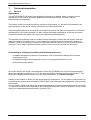
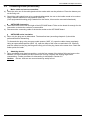
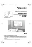
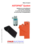
1.3
Description of the electronics
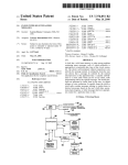
C Temperature control:
The temperature at the heat exchanger cylinder is controlled by a control unit consisting of a
microprocessor, an A/D converter and a triac unit. The actual temperature is determined by two NTC
sensors at the inlet (NTC1) and outlet (NTC2) (cf. Fig. 1, Block Diagram).
C Temperature display:
The actual temperature is displayed in the LCD as a mean value. At a temperature below 15 C, only
three bars at the bottom are shown and above 50 C, only three bars at the top. The three small displays
on the 220(S) and 260(S) models show the user-selectable temperatures. The frame outlines the current
selection according to which the temperature of the heat exchanger is being controlled.
On the model 200(S), the temperature of the heat exchanger is fixed.
C Safety cut-off at warmer inlet (heat exchanger rear side):
The safety cut-off at the warmer inlet is a device independent of the microcontroller. It checks whether NTC1
is hotter than the alarm limit (temperature value of second excessive temperature cut-off, see Section 1.4) In
the event of an alarm, the safety cut-off switches off relay K1. This interrupts the heating current and the
power supply for K1 and K2. Drop-out of the relay is indicated by the flashing alarm LED and the alarm tone.
If the heat exchanger cylinder cools to below the alarm limit, the device can be re-started manually. NTC1
cannot be affected by any conceivable defect of the safety cut-off at the warmer outlet or of NTC3.
C Safety cut-off at warmer outlet (heat exchanger front side):
The safety cut-off at the warmer outlet works according to the same principle as the safety cut-off at the inlet,
though it checks NTC3 (temperature value of the first excessive temperature cut-off, see Section 1.4) located
at the outlet and controls relay K2. NTC3 cannot be affected by any conceivable defect of the control system,
the safety cut-off at the warmer inlet, NTC1 or NTC2. The drop-out of the relay is indicated by the flashing
alarm LED and the alarm tone. If the heat exchanger cylinder cools to below the alarm limit, the device can
be re-started manually.
C Test devices:
Pressing the Start key checks whether relays K1 and K2 reliably cut power if so required. A fault signal is
sent to the safety cut-off at the warmer inlet followed by the safety cut-off at the warmer outlet. The
safety cut-offs react with an audible click. Following a successful test, the device switches on the
heating.
With alarm tests 1 and 2, the safety cut-offs at the warmer inlet and outlet can be tested individually (cf.
operating instructions, Section “PERIODICALLY RECURRING TEST MEASURES”).
C EEPROM memory:
An EEPROM is provided to store constants and operating states. Calibration data are also stored here.
Revision: 6 – 03/2010
Page 7
ASTOTHERM PLUS Repair Instructions
C Watchdog device:
The microprocessor is continuously monitored by a so-called watchdog circuit. If the microprocessor
becomes defective due to a malfunction, the watchdog circuit emits a signal and the device goes to
stand-by mode.
C Mains power failure bridging:
This is used to restart the device automatically in the previously selected state in the event of a brief
power failure. Automatic start is effected in the event of a power failure lasting up to 5 seconds, 30
seconds at most.
C ASTOLINE active insulation:
ASTOLINE is an auxiliary heating system controlled by current and voltage. If voltage or current are
above or below the permissible limit values, an alarm is activated. The board is operated with low-voltage
power.
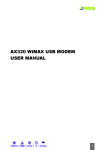
Safety cut-off at
warmer outlet
Heater
Safety cut-off at
warmer inlet
Watch-Dog
Power supply
electronic
Fig. 1 Electronics block diagram
Page 8
Revision: 6 – 03/2010
ASTOTHERM PLUS Repair Instructions
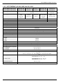
1.4
Technical Data
1.4.1 ASTOTHERM PLUS 200 and 200S
ASTOTHERM PLUS 200(S)
AP200(S) EU AP200(S) UK AP200(S) CH AP200(S) DK
AP200(S) NA
230-240 VAC "10%
47-63 Hz
100-115 VAC "10%
47-63 Hz
Line voltage
Power supply cord
SCHUKO plug
H 05 VVF
3x0.75
BS - plug
13A Fuse
H 05 VVF 3x1
Schweiz plug
H 05 VVF
3x0,75
DK - plug
DK2-Ia, DK25a
H 05 VVF
3x0.75
Hospital Grade Plug
NEMA 5-15P
SJO, SJT 18/3
Impedance of protective earth
≤ 0.2 Ohm
≤ 0.2 Ohm
Insulation resistance
> 2 MOhm
> 2 MOhm
AC leakage current
Primary Fuses
Secondary Fuses
Power input
Selfstart after mains power failure
Protection class
Protection level (IEC 601-1)
Humidity protection
Classification as per appendix IX
UMDNS Code
Dimensions
height
width
depth
Weight
≤ 0.2 mA
2x4A
2 x 0.63 A
250 W
5 to 30 sec.
I
defibrillation-proof applied part of type B
IPX4
IIb (Rule 9)
10-447
145 mm
135 mm
295 mm
2.9 kg
Warm- up time
approx. 1 min (20 C to 35 C)
Operating mode
continous operation
Permissible ambient temperature
for operation
for storage
Ambient operating humidity
Operation temperature
+16 C to +30 C
-40 C to +70 C
10 % to 90 %
40 C (" 0.5 °C)
1. safety cut-off
42.5 C (" 0.5 °C)
2. safety cut-off
43.5 C (" 0.5 °C)
heater bimetal cut-off
inadequate temperature alarm
Revision: 6 – 03/2010
65 C (" 5 °C)
below 32 C
Page 9
ASTOTHERM PLUS Repair Instructions
1.4.2 ASTOTHERM PLUS 220, 220S and 260, 260S
ASTOTHERM PLUS 220(S)
ASTOTHERM PLUS 260(S)
AP220(S) EU
AP260(S) EU
AP220(S) CH
AP260(S) CH
AP220(S) DK
AP260(S) DK
230-240 VAC "10%
47-63 Hz
Line voltage
Power supply cord
AP220(S) UK
AP260(S) UK
SCHUKOplug
H 05 VVF
3x0.75
BS - plug
13A Fuse
H 05 VVF 3x1
AP220(S) NA
AP260(S) NA
100-115 VAC "10%
47-63 Hz
Swiss plug
H 05 VVF
3x0.75
DK-plug
DK2-Ia, DK2-5a
H 05 VVF
3x0.75
Hospital Grade Plug
NEMA 5-15P
SJO, SJT 18/3
Impedance of protective earth
≤ 0.2 Ohm
≤ 0.2 Ohm
Insulation resistance
> 2 MOhm
> 2 MOhm
AC leakage current
Primary Fuses
Secondary Fuses
Power input
Selfstart after mains power failure
Protection class
Protection level (IEC 601-1)
Humidity protection
Classification as per appendix IX
UMDNS Code
Dimensions
height
width
depth
Weight
≤ 0.2 mA
2x4A
2 x 0.63 A
450 W
5 to 30 sec.
I
defibrillation-proof applied part of type B
IPX4
IIb (Rule 9)
10-447
145 mm
135 mm
295 mm
2.9 kg
Warm- up time
approx. 1 min (20 C to 35 C)
Operating mode
continous operation
Permissible ambient temperature
for operation
for storage
Ambient operating humidity
Operation temperature
1. safety cut-off
2. safety cut-off
heater bimetal cut-off
inadequate temperature alarm
Page 10
+16 C to +30 C
-40 C to +60 C
10 % to 90 %
37 C (" 0,5°C) / 39 C (" 0,5 °C) / 41 C (" 0,5 °C) up to SN ≤ 5000
or
39 C (" 0.5°C) / 41 C (" 0.5 °C) / 43 C (" 0.5 °C) from SN ≥ 5001
41°C-devices: 42.5 C (" 0.5 °C)
43°C-devices: 45.5 C (" 1°C)
41°C-devices: 43.5 C (" 0.5 °C)
43°C-devices: 46.0 C (" 1 °C)
65 C (" 5 °C)
4 C (" 0.5 °C) below operation temperature
Revision: 6 – 03/2010
ASTOTHERM PLUS Repair Instructions
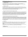
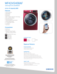
1.5
Terminal connecting plan
Fig. 2 Connections between electronic components
Revision: 6 – 03/2010
Page 11
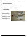
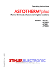
ASTOTHERM PLUS Repair Instructions
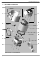
ASTOTHERM PLUS spare parts
34
12
10
31
18
14
19
23
21
7
33
22
8
1
20
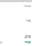
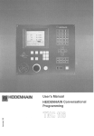
1.6
Fig. 3 Cross section of the ASTOTHERM PLUS
Page 12
Revision: 6 – 03/2010
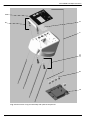
27
16
26
25
15
17
24
35
11
29
13a
28
32
13
(27)
30
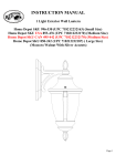
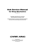
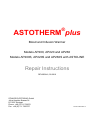
ASTOTHERM PLUS Repair Instructions
Fig. 4 Cross-section of bottom part assembly with optional components
Revision: 6 – 03/2010
Page 13
5
6
(2)
1
2
3
4
ASTOTHERM PLUS Repair Instructions
Fig. 5 Cross-section of top part assembly with optional components
Page 14
Revision: 6 – 03/2010
ASTOTHERM PLUS Repair Instructions
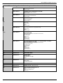
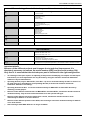
ASTOTHERM PLUS spare parts
When ordering please indicate always model number and serial number!
No.
Order number
Name
consist of
1
n.g.
n.g.
9751.4205.00
TOP PART OF HOUSING AP 200
9750.4205.00
TOP PART OF HOUSING AP 220/260
9751.4202.00
TOP PART OF HOUSING AP 200S
9750.4202.00
TOP PART OF HOUSING AP 220S
9770.4202.00
TOP PART OF HOUSING AP 260S
9750.8240.00
AL-Holder 4 mm
9750.8241.00
complete with handle, bolts and front panel
complete with handle, bolts and front panel
complete with handle, bolts and front panel
complete with handle, bolts and front panel
complete with handle, bolts and front panel
with fastening material
only from SN: BSEU1017, BSUK1021, BSCH1012, BSNA1001,
DSEU1323, DSUK1043, DSCH1012, DSNA1054
AL-Holder 6,8 mm
only from SN: HSEU1015, HSUK1018, HSCH1001, HSNA1015
with fastening material
2
9750.4202.14
HANDLE
3
9750.4200.13
DISPLAY COVER
4
9751.4200.05
FRONT PANEL AP 200
9751.4200.02
FRONT PANEL AP 200S
9750.4200.05
FRONT PANEL AP 220/260
9750.4200.02
FRONT PANEL AP 220S/260S
9750.2201.01-M841
OPERATING BOARD for M841 NTCs
5
with fastening material
1) 2) 3)
(red or black NTC wire insulation)
tested and adjusted for Type
9750.2201.01-Glas
OPERATING BOARD for glass NTCs
1) 2) 3)
(white NTC wire insulation)
tested and adjusted for Type
6
9750.2200.14
KEY EXTENSION (1 Piece)
7
9750.2101.01-M841
TRANSFORMER BOARD for M841 NTCs (41°C)
1) 4) 5)
(red or black NTC wire insulation)
tested
9750.2101.01-Glas
TRANSFORMER BOARD for glass NTCs (41°C)
1) 4) 5)
(white NTC wire insulation)
tested
0450.2101.43
TRANSFORMER BOARD (43°C)
1) 4) 5)
(white NTC wire insulation)
tested
8
9750.8100.02
AXLE HEAT PROTECTION SLEEVE
10
8510.0305.01
BUFFER (2 Pieces)
11
9750.4100.09
CABLE GLAND PG9
Revision: 6 – 03/2010
1Cable gland
1Counter nut
Page 15
ASTOTHERM PLUS Repair Instructions
When ordering please indicate always model number and serial number!
12
13
13a
9750.4100.10
POWER SUPPLY CORD SCHUKO
9750.4100.12
POWER SUPPLY CORD GREAT BRITAIN
9750.4100.16
POWER SUPPLY CORD SWITZERLAND
9750.4100.17
POWER SUPPLY CORD USA
9750.4100.00
BOTTOM PART OF HOUSING AP 200/220/260
9750.4101.00
BOTTOM PART OF HOUSING AP 200/220/260 - PA
9750.4102.10
BOTTOM PART OF HOUSING AP 200S/220S/260S WITH ASTOLINE
DEVICE SOCKET
1Power supply cord SCHUKO
1Cable tie 90mm
1Power supply cord GREAT BRITAIN
1Cable tie 90mm
1Power supply cord SWITZERLAND
1Cable tie 90mm
1Power supply cord USA
1Sticker GROUNDING
1Cable tie 90mm
1Bottom part
1Sticker ASTO
2Buffer
2Cable tie 90mm
1Bottom part with drill-hole for equipotential bonding
1Sticker ASTO
2Buffer
2Cable tie 90mm
1Bottom part with drill-hole for ASTOLINE socket connector
1AL-Device Socket
1AL arrow sticker
1Sticker ASTO
2Buffer
2Cable tie 90mm
1Protective cap
1Crimp connector
9750.4103.10
BOTTOM PART OF HOUSING AP 200S/220S/260S - PA WITH
ASTOLINE DEVICE SOCKET
1Bottom part with drill-hole for ASTOLINE socket connector
and equipotential bonding
1AL-Device Socket
1AL arrow sticker
1Sticker ASTO
2Buffer
2Cable tie 90mm
1Protective cap
1Crimp connection
14
9750.4300.01
INTERMEDIATE RING
15
9750.5100.04
THREADED SHAFT
16
9750.5102.00
CLAMP RIGHT
1Clamp right
1Rectangular nut right
1Pad
17
9750.5100.01
BASEPLATE
1Base plate
1Identification label
18
9750.4300.02
SPACING BOLT (1 Piece)
19
9720.3725.02
O-RING 114.02 x 1,78 (2 Pieces)
20
9750.8100.00
HEAT PROTECTION SLEEVE AP
Page 16
2Half part Heat protection sleeve
1Axle
2Sticker ASTOTHERM PLUS
1Fixing cord
Revision: 6 – 03/2010
ASTOTHERM PLUS Repair Instructions
When ordering please indicate always model number and serial number!
21
9750.3132.00-41
HEAT EXCHANGER COMPLETE
GROOVE 4 MM (AP200, 220) 40/41°C 1) 6) 7)
1Earth conductor 200mm mounted
4Insulating cover
1Ferrit-Ring
2Cable tie 90mm
9750.3132.00-43
HEAT EXCHANGER COMPLETE
GROOVE 4 MM (AP220) 43°C 1) 6) 7)
1Earth conductor 200mm mounted
4Insulating cover
1Ferrit-Ring
2Cable tie 90mm
9770.3132.00-41
HEAT EXCHANGER COMPLETE
GROOVE 6.7 MM (AP260) 41°C 1) 6) 7)
1Earth conductor 200mm mounted
4Insulating cover
1Ferrit-Ring
2Cable tie 90mm
9770.3132.00-43
HEAT EXCHANGER COMPLETE
GROOVE 6.7 MM (AP260) 43°C 1) 6) 7)
1Earth conductor 200mm mounted
4Insulating cover
1Ferrit-Ring
2Cable tie 90mm
n.g.
9750.8110.01
FIXING CORD HEAT PROTECTION SLEEVE
n.g.
9524.2620
FERRIT-RING
22
9950.2100.20
FIXING STRIP
23
9750.8230.00
ASTOLINE ACTIVE INSULATION 4 MM
9750.8231.00
ASTOLINE ACTIVE INSULATION 6.8 MM
24
9850.5100.10
KNURLED SCREW
25
9750.5103.00
26
9750.5104.00
27
9750.5101.00
28
9750.8230.17
29
9750.8230.02
30
9750.8220.03
31
9750.8240.04
32
9750.4184.00
Revision: 6 – 03/2010
CLAMP LEFT
1Clamp left
1Rectangular nut left
1Pad
HAND WHEEL
1Hand wheel with Nut M8
1Grip cover
1Head screw M4x8
1Washer A4,3
DEVICE FIXING AP COMPLETE
PROTECTION CAP for ASTOLINE device socket
1Protection cap
1Crimp connector
ASTOLINE DEVICE SOCKET
1AL device socket
1AL arrow sticker
1Counter nut
ASTOLINE BOARD
1AL-Board
2Pan head tapping screw
AL-INSULATION PLATE
EQUIPOTENTIAL RETROFITTING SET
1Earth conductor 150mm
1Connector dia. 6 mm
2Nut M6
2Washer R6,4
1Serrated lock washer V6,4
1O-ring 5x1
1Assembly plan
1Drilling gauge
1Sticker
Page 17
ASTOTHERM PLUS Repair Instructions
When ordering please indicate always model number and serial number!
9750.8230.20
33
AL-PLUG (for soldering)
1 AL arrow sticker
9750.4201.14
34
SET O-RINGS 4x1 MM
4 for housing screws
2 for handle
2Cable tie 90mm
9750.5101.11
35
SET O-RINGS 5x1 MM
4 for device fixing AP
1 for equipotential bonding plug
2Cable tie
n.g.
n.g.
n.g.
n.g.
9850.6001.00
PACKAGE AP COMPLETE
1Internal carton
1EPS insert botton
1EPS insert top
1Outer carton
1Sticker package AP blank
9850.6003.01
OUTER CARTON SINGLE AP
9850.6003.02
OUTER CARTON DOUBLE AP
9850.6003.03
OUTER CARTON FOURFOLD AP
TEST-EQUIPMENT
n.g.
n.g.
n.g.
9950.9000.02
POWER RESISTORS SET
4Pieces 15 Ohm 10 W "5 %
1Piece 100 Ohm 10 W "5 %
9950.9000.03
CD-ROM AP Calibration Software
1 Interface (230 VAC)
1 Instructions “AP Calibration Program”
1 Instructions “Eliminating microprocessor faults”
9950.9000.35
Test Thermistor tip 3.5 mm
to measure the temperature dependent on the resistance with multimeter and table
Important details
Because of the different variants and changes due to technical improvement it is
absolutely necessary to indicate the model number (REF) and the serial number (SN).
Only then it is ensured that the desired spare part is delivered in the right configuration.
1)
2)
3)
4)
5)
6)
7)
An exchange of this part requires an adjusting of temperature and display (see chapter 4 of the Repair
Instructions). An exact adjustment can only be made by using the interface and the AP Calibration
Software or by the manufacturer.
Operating boards (only for Glass-NTCs, from Rev. 3.1) can be used alternatively for 40°C or for 41°C or
for 43°C devices by uploading an corresponding data file (to do this the interface and the AP
Calibration Software is necessary).
Operating boards from Rev. 3.1 can be used alternatively for M841-NTC or Glass-NTC devices by
switching a solder jumper.
Because of the different characteristics of M841-NTCs and Glass-NTCs, transformer boards cannot be
used alternatively. They must be ordered and built in for the specific NTC type.
Because of the different excessive temperature cut-offs, transformer boards cannot be used
alternatively for 40/41°C or for 43°C devices.
Because of the different position of the NTCs, heat exchanger cannot be used alternatively for 40/41°C
or for 43°C devices.
Heat exchanger with M841-NTCs are no longer available.
Page 18
Revision: 6 – 03/2010
ASTOTHERM PLUS Repair Instructions
2 General guidelines and principles for the repair of ASTOTHERM PLUS
blood and infusion warmers
2.1
Technical Service and Ordering Spare Parts
STIHLER ELECTRONIC GmbH
Julius-Hoelder-Str. 36
70597 Stuttgart
Germany
Tel: +49 (0) 711-720670
Fax: +49 (0) 711-7206757
www.stihlerelectronic.de
E-mail: [email protected]
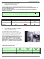
When making requests or ordering spare parts, please state the reference and serial number of
the device in question. You can find them on the device rating plate:
Fig. 6 Information on the rating plate
2.2
Guarantee repairs
A 12-month guarantee is granted. During the guarantee period, the manufacturer will remedy all
defects due to material or manufacturing faults free of charge either by repair or replacement.
This guarantee does not cover any other damage. Damage due to misuse or improper handling,
excessive force or regular wear is not covered by this guarantee. This also applies to
interventions by persons other than those authorised by the manufacturer or if the original
condition is changed.
If damage occurs during the guarantee period, please clean the device and send it to a sales
location near you or directly to STIHLER ELECTRONIC. The costs of transport and packaging are
for the sender's account.
2.3
Liability
The manufacturer shall only be liable for the safety, reliability and performance of the device if all
operating, maintenance and testing procedures comply with the procedures communicated by the
manufacturer and are carried out by properly trained and qualified personnel; if -when necessaryonly original spare parts are used to replace components; if assembly and repairs are only carried
out by authorised personnel or an authorised service centre; if the electrical systems comply with
the locally applicable instructions and regulations and the IEC requirements and if the device is
used in keeping with the instructions of use for the intended purpose and at a suitable location.
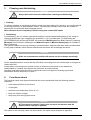
CAUTION
The fact that technical documents or spare parts are made available does
not imply any authorisation on the part of the manufacturer to open or
repair the device.
Revision: 6 – 03/2010
Page 19
ASTOTHERM PLUS Repair Instructions
2.4
Important instructions
All tests must be carried out by properly qualified staff, i.e. staff who have the relevant expert
professional training, knowledge and experience and are familiar with the relevant
technologies, standards and local rules and regulations. Personnel who have to assess safety
must be able to recognise any consequences and dangers caused by devices which do not
comply with the requirements.
The measuring equipment must comply with the relevant standards.
All repair activities, all tests carried out and their results must be recorded.
The pattern approval is invalidated if the device is no longer in its original state. You must
therefore use only original spare parts.
Due to the safety risks, electronic PWBs must only be repaired by the manufacturer. If
they are faulty they must always be replaced in their entirety.
Any heat exchanger cylinder is an individual item from a heat engineering point of view, due to its
complex production and the large number of influencing variables (production tolerances in the
manufacture of the heating system, NTCs etc.). For this reason, every electronic temperature
control needs to be specifically matched to “its” heat exchanger cylinder in order to achieve
sufficiently small control fluctuation later on.
The NTCs form the core of the blood warmer. Their sensitivity means that it is prohibited to
change their position or replace them. When dismantling or assembling the device, ensure
that the NTCs/their connecting wires are not damaged.
Defective NTCs may be replaced only by the manufacturer. The complete heat exchanger
cylinder/transformer board/operating board unit needs to be returned for this purpose.
For all thermal test work pay attention to room temperature and ambient effects!
As the control temperature is set accurate to a few tenths of a C, note the following points:
-
avoid external effects on the heat exchanger unit /electronics to be measured
no draughts
constant room temperature (20 to 26 C)
keep out of direct sunlight
keep away from strong light sources
CAUTION
A functional check (see Section 4) and a continuous duty test (see
Section 9) must be performed after any repair to the device.
Page 20
Revision: 6 – 03/2010
ASTOTHERM PLUS Repair Instructions
2.5
Procedure for ASTOTHERM PLUS repairs
Fig. 7 Flow chart for repairs
Revision: 6 – 03/2010
Page 21
ASTOTHERM PLUS Repair Instructions
3
Cleaning and disinfecting
CAUTION
Always disconnect from the mains before cleaning and disinfecting.
Cleaning
To remove splashes of physiological saline or blood from the surface of the housing, use a soft cloth with
a mild soap solution or a special plastic cleaner. Commercially-available cotton buds are suitable for
cleaning the circumferential heat exchanger groove.
Never immerse device completely in fluid or bring into contact with steam!
Disinfecting
For disinfecting, use ¼% sodium hypochlorite solution or alcohol-based disinfectants of the “ready-touse spray disinfectant” type containing low quantities (< 0,2 %) of aldehydes. For disinfecting the
ASTOTHERM PLUS and the ASTOLINE, we recommend Bacillol plus from Bode Chemie in Hamburg,
Meliseptol from B. Braun in Melsungen and Mikrozid Liquid or Mikrozid Pumpspray from Schülke &
Mayr in Hamburg.
The operator should not use any cleaning or decontamination methods other than those recommended.
If using other methods, check with the manufacturer that these will not damage the device.
CAUTION
Under no circumstances sterilise with steam, hot air or thermo-chemically!
On the dismantled device, ensure that the NTCs/their connecting wires are not damaged or brought into
contact with fluid.
If metal parts (connecting wires, printed circuits) of electronic components on the boards are
contaminated or corroded, then replace the electronics for safety reasons.
Corroded metal parts inside the device suggest the use of non-approved cleaning agents and
disinfectants and the destruction of seals.
4
Functional check
The functional check must be performed with the device assembled. Note the following ambient
conditions:
C avoid external effects on the device
C no draughts
C constant room temperature (20 to 26 C)
C keep out of direct sunlight
C keep away from strong light sources
CAUTION
All Tests must be passed. If any errors are found, the warmer must be
repaired before using it on patients.
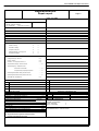
The results of the functional check can be entered in the repair report (template in appendix).
Page 22
Revision: 6 – 03/2010
ASTOTHERM PLUS Repair Instructions
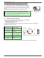
4.1
Check display devices (LCD and LED):
Connect the device to the mains at room temperature.
All the display devices should come on for a brief period (cf. Figs 8 and 9).
Fig. 8 Display elements of model 200(S)
4.2
Fig. 9 Display elements of models 220(S) and 260(S)
Check heating-up time
Switch on the device and start the warmer (cf. operating instructions, Section “COMMISSIONING”) without
selecting a temperature. Watch the temperature display during heating up. Temperature increases rapidly at
first, then more slowly.
AP 200
Heating-up time
20°C to 35°C
4.3
max. 1.5 minutes
AP220/260
max. 1 minute
Check display temperature fluctuation
(better with heat protection sleeve)
After a few minutes the displayed temperature is reaching the set temperature and is then deviating only
marginally.
Fluctuation of the display temperature due to control may not exceed " 0.2 C in load-free
mode.
Revision: 6 – 03/2010
Page 23
ASTOTHERM PLUS Repair Instructions
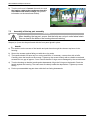
4.4
Check temperature in control state
(better with heat protection sleeve)
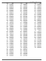
The test thermistor (order-No. 9950.9000.35), a calibrated ohmmeter and the table of
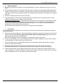
resistance/temperature in the appendix of these repair instructions are required for this purpose.
Insert the test thermistor into the rear measuring bore on the side of the heat exchanger (see Fig. 10)
and connect it with the ohmmeter.
Wait until the indicated value is stable. Then read the indicated value and take the corresponding
temperature out of the table.
Deviation of the control temperature measured with the test thermistor from the set
control temperature may not exceed " 0.4 C. The displayed temperature of the warmer
may not exceed more than 0.4°C from the selected and the measured temperature.
Example:
Set temperature
measured temperature
displayed temperature of
41°C
41°C
41°C
40.8°C
41.2°C
40.5°C
ok
ok
not ok
40.6 – 41.2°C
40.7°C
40.8°C
ok
not ok
ok
the warmer
4.5
Test temperature overshoot on heating
(without heat protection sleeve)
The test thermistor (order-No. 9950.9000.35), a
calibrated ohmmeter and the table of resistance/temperature in the appendix of these repair instructions are
required for this purpose. Operate warmer with the
highest set temperature (TSet) and then switch off the
device. Insert the test thermistor into the rear measuring
bore on the side of the heat exchanger (see Fig. 10) and
connect it with the ohmmeter. Allow heat exchanger
cylinder to cool down by 1 C " 0.2 K. (If the device is
switched back on, the temperature of the heat exchanger
can be read off on the display. The alarm should sound
continuously.)
Fig. 10 Measuring control temperature and
Start the warmer when the TSet -1°C cooling limit is
temperature overshoot
reached. Look at the display of the ohmmeter and jot
down the lowest measured resistance. Take the corresponding temperature out of the table and
compare it with the following values:
max. set temperature
Start at circa TSet – 1 °C =
max. allowed temperature overshoot
Page 24
AP200
AP220/260
AP220/260
40°C
41°C
43°C
38.8 – 39.2°C
39.8 – 40.2°C
41.8 – 42.2°C
40.7 C
42.2°C
43.5 C
Revision: 6 – 03/2010
ASTOTHERM PLUS Repair Instructions
4.6
Alarm test functions
The ASTOTHERM PLUS is fitted with alarm test functions. These simulate the failure of temperature
sensors and thus lead to activation of alarm cut-offs. The description which follows relates to
ASTOTHERM PLUS 220(S) and 260(S) models with adjustable selected temperature. For the
ASTOTHERM PLUS 200(S) models, there are no keys for changing temperature. In this case, the key
names in brackets apply (cf. Figs 8 and 9 and operating instructions, Section “CONTROL PANEL”).
Checking excessive temperature alarms:
Test 1: Start device at middle selected temperature. Keep "Start" key depressed for three seconds
to start the internal test cycle.
LCD display alternately displays "t1" and actual temperature. After a brief time, the device
should react with the excessive temperature alarm.
Re-start the device by pressing the "Start" key.
Test 2: Start device at upper selected temperature. Keep "Increase" key (top "Test function" key)
depressed for three seconds to start the internal test cycle.
LCD display alternately displays "t2" and actual temperature. After a brief time, the device
should react with the excessive temperature alarm.
Re-start the device by pressing the "Start" key.
Checking low temperature alarm:
Test 3: Start device at bottom selected temperature. Remove heat protection sleeve. Keep "Decrease"
key (bottom "Test function" key) depressed for three seconds to start the internal test cycle.
LCD display alternately displays "t3" and actual temperature. Once the device has cooled
down about approximately 4°C (AP220/260) respective to 32 C (AP200) , the device
should react with the low temperature alarm.
Switch off the device using the "Device On/Off" key. After this test, the device cannot be restarted
by pressing the "Start" key.
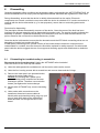
4.7
Checking safety cut-offs
Note: the temperature display reflects the mean value of the temperature of the heat exchanger
(between front and rear side).
By testing the safety cut-off of warmer rear side or warmer front side the heat exchanger is only heated
up only at a small area. In this condition the display shows not the real temperature of the small heated
area (it shows the mean value of the heated and unheated area). The formula below shows the
background.
TDisplay = (Tinlet + TOutlet) / 2
TDisplay
TInlet
TOutlet
TCut-off
TSet
Revision: 6 – 03/2010
or
TCut-off = (TDisplay x 2) - TSet
actual temperature which is indicated on the display
actual temperature inside the heat exchanger in the area of the rear measuring bore
actual temperature inside the heat exchanger in the area of the front measuring bore
real temperature in the moment of switching off
selected temperature on the side which will not be warmed up from external
Page 25
ASTOTHERM PLUS Repair Instructions
CAUTION
Please observe the following instructions:
1. Warmer has to be calibrated and if necessary to be adjusted
2. Warmer needs to work in the control state for a few minutes to ensure that the
heat exchanger is heated through evenly.
3. Immediately before testing the display of the warmer should indicate 40°C ±
0.1°C (AP200), 41°C or 43°C ± 0.1°C respectively (AP220/260).
4. Between the tests of “safety cut-off warmer inlet” (backside) and “safety cut-off
warmer outlet” (frontside) you have wait until the temperature has dropped to
the set temperature (see 3.).
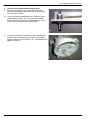
Safety cut-off at the warmer inlet
Using a hot-air blower or hairdryer on the lowest temperature
setting, heat up the heat exchanger in the area below of the
rear temperature measuring bore (bottom right on bottom
part of housing, see mark in Fig. 11) until the device activates
the alarm. Allow the device to cool down and keep pressing
the Start key until it can be re-started. In the moment when
the warmer can be re-started the temperature display should
be within the range of values given in the table.
Fig. 11 Testing safety cut-off at warmer inlet
Safety cut-off temperature
at warmer inlet (backside)
Nominal value warmer
display
TDisplay
real value
TCut-off
AP 200 (S)
TSet = 40°C
AP 220/260 (S)
TSet = 41°C
AP 220/260 (S)
TSet = 43°C
41.5 to 42.0°C
42.0 to 42.5°C
43.8 to 44.7°C
43.1 to 43.9C
43.1 to 43.9C
44.6 to 46.4°C
Safety cut-off at the warmer outlet
Allow the device to cool down to the set temperature and
repeat the measurement as carried out above below the
front temperature measuring bore (bottom left on top part of
housing, see mark in Fig. 12).
The temperature in the moment when the warmer can be
re-started should be within the range of values given in the
table when the alarm occurs.
Fig. 12 Testing safety cut-off at warmer outlet
Safety cut-off temperature
at warmer outlet (frontside)
AP 200 (S)
TSet = 40°C
AP 220/260 (S)
TSet = 41°C
AP 220/260 (S)
TSet = 43°C
Nominal value
warmer display
TDisplay
41.0 to 41.7°C
41.5 to 42.2°C
44.0 to 45.0°C
real value
TCut-off
42.1 to 42.9C
42.1 to 42.9C
45.1 to 46.9°C
Page 26
Revision: 6 – 03/2010
ASTOTHERM PLUS Repair Instructions
Functional check of devices with ASTOLINE active insulation
(Models 200S, 220S, 260S only)
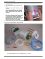
4.8
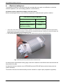
Measuring resistance of ASTOLINE active insulation
Using a resistance measuring device, measure the electrical resistance
between Pin 1 and Pin 3 on the plug of the flexible silicone groove (see
Fig. 13)
In cold condition ASTOLINE temperature = ambient temperature.
Fig. 13 Pin assignment on the
ASTOLINE plug
The cold resistance of the ASTOLINE active insulation
must be 54 " 3.5 ohms at an ambient temperature of 20 C*.
* add +0,26 ohms /1K higher ambient temperature
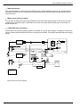
4.9
Testing ASTOLINE connection
For the test a set of power resistors is required (order no. 9950.9000.02).
The power resistors should have the following values:
- 4 pieces with 15 Ohm 10W " 5%
- 1 piece with 100 Ohm 10W " 5%
They should be connected to the circuit according to the table below (and Fig. 14), triggering the
appropriate reaction on the device.
Resistance RX [Ω]
Reaction required
30
Alarm
45
no Alarm
KabelAL-Plug
stecker
white
Pin 1
Pin 3
60
100
4
Measurement of voltage
U = 20.8 – 21.4 VDC
no Alarm
U
RX
brown
Fig. 14 Test circuit for devices with an ASTOLINE
Alarm
After an alarm reaction, the device must be restarted before further tests can be performed.
Revision: 6 – 03/2010
Page 27
ASTOTHERM PLUS Repair Instructions
5
Troubleshooting
If one or more items of the functional check are failed, then troubleshooting will be required.
Compare the activities of the display devices with the operating and alarm states also described in the
operating instructions (Section “CONTROL PANEL”).
The table below is intended to assist in troubleshooting and help eliminate faults.
Renewal of individual components of the heat exchanger cylinder unit including transformer
board and operating board requires calibration and if necessary adjusting of the calibration
values with the interface. An exact adjustment can only carried out with the interface and the
accompanying software or by the manufacturer!
A modified device may not be commissioned without calibration and testing. If a fault has been found on a
component and there is no interface available, the complete device should be returned to the manufacturer
with a brief description of the fault.
Fault
Possible causes
Remedy
Display devices (LED, LCD) do not
light up after plugging in - device
cannot be started
Lack of/incorrect power supply
Y Check socket/fuse, compare mains voltage
with details on rating plate.
Mains connection cable or mains plug defective
Y Change mains connection cable.
Primary fuse defective (impact, short-circuit in
heating system, in mains transformer or on
board)
Measure resistance of heating system (see
Section 6.4)
If heating system OK:
Y change primary fuse; if device still not OK
Y transformer board; return complete
electronics system with heat exchanger.
If heating system not OK:
Y return complete electronics system with
heat exchanger.
Device switched on - device cannot Secondary fuses defective
be started
Y Change secondary fuses on transformer
board.
Operating board defective
Y Change operating board and calibrate and
adjust it if necessary.
Transformer board defective
Y Change transformer board and calibrate the
unit. Adjust it if necessary
NTC 1, 2 or 3 defective
Y Change heat exchanger and calibrate the
unit. Adjust it if necessary
On models with ASTOLINE
Switch off ASTOLINE; if warmer can be
started, check the following
"ASTOLINE On/Off" key pressed but ASTOLINE Y Connect ASTOLINE
not connected
ASTOLINE device socket defective
Check resistance.
Y Replace device socket.
ASTOLINE board defective
Y Replace ASTOLINE board.
ASTOLINE defective
Check resistance.
Y Replace ASTOLINE if necessary.
Device switched on - device cannot Control-NTC (NTC1) or Display-NTC (NTC2)
defect.
be started, bars only on
temperature display
Device is colder than 0°C
Page 28
Y Change heat exchanger and calibrate the
unit. Adjust it if necessary
Yplace device in a warmer location.
Revision: 6 – 03/2010
ASTOTHERM PLUS Repair Instructions
Fault
Possible causes
Remedy
Device can be started, but heat
exchanger cylinder does not get
hot
Heating system defective
Measure resistance of heating system.
In event of deviation from specified value (see
Section 6.4):
Y Change heat exchanger and calibrate the
unit. Adjust it if necessary
Operating board defective
Y Change operating board and calibrate and
adjust it if necessary.
Defect on transformer board (relay, optocoupler, Y Change transformer board and calibrate the
triac, control LED)
unit. Adjust it if necessary
Device activates alarm during
heating up
Device in alarm state, device
cannot be started until display
temperatures are below 30 C
Electronics defective (after fall, water damage or Y Change operating or transformer board and
use of non-permitted disinfectants)
calibrate the unit. Adjust it if necessary
NTC defect (NTC1, NTC2, NTC3)
Y Change heat exchanger and calibrate the
unit. Adjust it if necessary
External effect (sunlight, heating, airconditioning, too hot a medical solution used)
Y Select a different location.
Y Do not use overheated medical solutions.
Bimetal-thermal cut-off defective
Y Change heat exchanger and calibrate the
unit. Adjust it if necessary
Check whether device got too hot (approx. 65
C):
- if due to external thermal effects:
Y thermal cut-off OK.
- if not due to external effects, thermal cut-off
defective:
Y Change heat exchanger and calibrate the
unit. Adjust it if necessary
Bimetall-thermal cut-off has switched off
External effect (sunlight, heating, airDisplay temperature above the
conditioning, too hot a medical solution used)
tolerance of the control
temperature set in the control state
Control NTC (NTC1) is
incorrectly adjusted
or defective
Y Select a different location.
Y Do not use overheated medical solutions.
Check whether actual temperature of heat
exchanger corresponds with display. If so,
Y Adjust control temperature (NTC1)
Y Change heat exchanger and calibrate the
unit. Adjust it if necessary
If not, see next line
Display NTC (NTC2)
is incorrectly adjusted
or defective
YAdjust temperature display (NTC2)
Y Change heat exchanger and calibrate the
unit. Adjust it if necessary
Models with ASTOLINE: internal heating up due Y Take off heat protection sleeve.
Display temperature above the
to heat from transformer with ASTOLINE switY Switch off ASTOLINE (unless in sole use).
tolerance of the control
temperature set in the control state ched on and not enough heat being taken away
at the heat exchanger
Software alarm (after connecting to Program fault (microprocessor)
the mains) alarm LED and alarm
sound only
Y Unplug device, restart after approx. 1
minute.
Y Reset device: keep "Decrease" and
"Increase" keys/ both test keys depressed for
approx. 5 seconds.
then disconnect from and connect to the
mains
Y Transfer the original-data file*
Y Change operating board and calibrate the
unit. Adjust it if necessary.
*available at manufacturer
Revision: 6 – 03/2010
Page 29
ASTOTHERM PLUS Repair Instructions
6
Dismantling
Generally-applicable safety conditions and precautions apply to dismantling the ASTOTHERM PLUS. All
electrical installations must comply with the applicable national standards and regulations in each case.
During dismantling, ensure that the device is reliably disconnected from the mains. Electronic
components can contain a residual current even after the device is switched off. If a mains connection is
required with the device dismantled (e.g. for test purposes), ensure that no conducting parts can be
touched.
Procedure for dismantling:
The description follows the assembly structure of the device. Once the cause of the fault has been
localised, the relevant assembly can be dismantled into smaller units. The section heading indicates the
assembly in question. If potential dismantling is not described, then this is either because there is no
point or because the unit should not be dismantled any further.
Once the device is dismantled, ensure that the electronics and the NTCs/their connecting wires are not
damaged or brought into contact with fluid.
If metal parts (connecting wires, printed circuits) of the boards and the electronic components are
contaminated or corroded, then the electronics should be replaced for safety reasons. Corroded metal
parts inside the device suggest the use of non-approved cleaning agents and disinfectants or defective
seals.
6.1
Dismantling for troubleshooting in assemblies
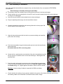
Disconnect device from the mains! Unplug the ASTOLINE active insulation!
Place the device on the front top and handle.
a) Undo the cable gland with a suitable tool until the mains cable can be moved.
b) Undo the four housing screws with a screwdriver and remove these and the O-rings.
c) Remove the lower part in an upward direction,
pushing the mains cable after it.
Caution: the housing has a plastic pin to
prevent twisting which reaches into the heat
exchanger cylinder. Therefore never twist the
bottom part against the heat exchanger.
d) Models with ASTOLINE only: remove insulating
plate.
e) Undo mains cable connections on the
transformer board and remove cable tie.
Models with equipotential bonding plug only: pull
plug of earth wire cable off the transformer
board and take out through the bore of the
board.
Fig. 14 Lifting off bottom part of housing
c)
Page 30
Revision: 6 – 03/2010
ASTOTHERM PLUS Repair Instructions
f)
Unscrew the four spacing bolts of the bolts, undo the cable tie of the heating cable and take off the
intermediate ring.
g) Take the heat exchanger cylinder off the top
part.
Caution: the housing has a plastic pin to prevent
twisting which rises up into the heat exchanger.
Therefore take the top part in both hands and
using your thumbs, push the heat exchanger
cylinder upwards against the outlet side and
remove. Never twist the top part and the heat
exchanger.
h) Push the parts only far enough apart to allow the
electrical connection between the transformer
board and the operating board to be disconnected. Disconnect the connection between the
transformer board and the operating board. Do
not remove the fixing strip which retains the
transformer board in the heat exchanger.
i)
g)
Prevent the heat exchanger/transformer board assembly from rolling away.
The device is now dismantled into individual groups.
Fig. 15 ASTOTHERM PLUS and ASTOLINE dismantled into assemblies
Revision: 6 – 03/2010
Page 31
ASTOTHERM PLUS Repair Instructions
6.2
Dismantling bottom part assembly
C
Mains cable and screw connection:
a) Undo the union nut of the cable gland until the mains cable can be pulled out. Place the bottom part
on the fixing unit.
b) Should the cable gland have to be completely dismantled, the nut on the inside needs to be undone
using a double cranked hex ring spanner (WAF 22).
(If an equipotential bonding plug is attached to the device, this must be removed beforehand).
C
ASTOLINE electronics:
c) Undo the screws on the left and right of the ASTOLINE board. Take out the board far enough for the
connection to the device socket to be accessible.
d) Disconnect the connecting cable of the device socket to the ASTOLINE board.
C
ASTOLINE active insulation:
e) Note: only the plug can be dismantled. The described test (according chapter 4.8) should be
performed before dismantling.
To dismantle the plug using an open-ended spanner (WAF 10), open the cable clamp completely.
Using an open-ended spanner (WAF 12), open the hasp of the union nut and take it off. Carefully
push the cable into the plug housing and evenly pull out the plug insert at the same time. Check the
solder points for break.
f)
C
Attaching device:
Using a suitable cross-head screwdriver, undo the four screws of the device fixing and remove the
washers. Lift off the bottom part and remove the O-rings. Replace the sealing rings before
reassembling. Further procedure for dismantling is described in Section 6.5.
Caution: the two bolts are not secured and may easily fall out.
Page 32
Revision: 6 – 03/2010
ASTOTHERM PLUS Repair Instructions
6.3
Dismantling the top part assembly
CAUTION
When handling the top part, ensure that the bolts are not put under lateral strain this can lead to fracture of the bolts or of the housing domes.
C
Operating board:
a) Place the top part on its front. Using a suitable cross-head screwdriver, remove the two top screws
on the operating board. Slightly lift the operating board by the connecting cable until it slides out of
the bottom screw retainer. Take the board out upwards without tilting. If necessary, loosen the two
bottom mounting screws.
Defective operating boards can only be repaired by the manufacturer.
C
Handle:
b) Using a suitable cross-head screwdriver, unscrew the screws of the handle and remove the
washers. Remove the handle and the O-rings on the outside.
C
Front panel:
c) Loosen the front panel with a knife or a needle and remove the display cover.
6.4
Dismantling the heat exchanger cylinder assembly
When handling this assembly ensure that:
- it is reliably disconnected from the mains,
- the fitted transformer board is prevented from moving by the fixing strip,
- the heat exchanger is prevented from rolling away.
a) Disconnect the electrical plug connections between the heat exchanger and the transformer board
(heating and earth wire cable).
Measure heating system resistance between the numbered heating cables.
Specified values: 1 - 2 6 125 to 145 ohm;
1 - 4 6 < 1 ohm;
1 - 3 6 62.5 to 72.5 ohm;
2 - 3 6 62.5 to 72.5 ohm.
b) Turn the heat exchanger cylinder so that the secured transformer board is accessible from
underneath.
c) Heat the soldering points of the NTC lines using a soldering iron and pull them out with tweezers.
(One NTC is attached at the inlet side of the heat exchanger (mains side of the transformer board)
and two NTCs at the outlet side (plug connection for the operating board)).
d) Turn the heat exchanger round again, take hold of the top centre of the fixing strip and pull it out.
e) Take hold of the transformer board in the area of the plug connector to the operating board and lift
upwards. Push the board through the heat exchanger.
f)
If polluted remove the sealing rings in both end faces of the heat exchanger using tweezers or
another suitable tool and clean the groove.
Revision: 6 – 03/2010
Page 33
ASTOTHERM PLUS Repair Instructions
6.5
Dismantling the device fixing assembly
C
Dismantling for cleaning purposes:
a) Push the bolts out of the base plate using a drift.
b) Push the base plate off the clamps.
c) Unscrew the clamp on the right of the threaded shaft. Remove the rectangular nut on the right and
unscrew the knurled screw.
Clean the fixing unit as dismantled thus far with the cleaning agents/ disinfectants mentioned in Section
3. To do so, turn the threaded shaft to and from in the clamp up to the ends.
C
Complete dismantling:
Further assembly may lead to destruction of the grip cover.
d) Lever out the grip cover with a fine
screwdriver.
e) Turn the hand wheel so that it is flush
with the left-hand clamp. Using a
suitable screw-driver, undo the
cylinder bolt and unscrew it (it is
secured with adhesive). Remove the
washer.
f)
Hold the threaded shaft with pliers in
the cylindrical area and unscrew the
hand wheel. Remove the big washer.
g) Unscrew the threaded shaft from the
left-hand clamp and take out the
rectangular nut on the left.
Knurled screw
Left
clamp
Screw Washer
M4x10 4.3
Washer
8.4
Right
clamp
Right-hand
rectangular
nut
Left-hand
rectangular nut
Threaded shaft
Grip cover
Star grip
Base plate
Bolts
Retainer
washer
Fig. 16 Device fixing assembly disjointed completely
Page 34
Revision: 6 – 03/2010
ASTOTHERM PLUS Repair Instructions
7
Assembling the device
The safety information in Section 6 applies to assembly of the ASTOTHERM PLUS device!
Procedure for assembly:
assembly steps are described in individual sections by assembly group.
7.1
Assembling the device fixing assembly
a) Prepare all the parts as shown in Fig. 16. Ensure that the base plate with the depression for the
rating plate is facing upwards. Arrange the two clamps so that they can be suspended in a medical
rail system. The lug needs to be on top of the clamp for this purpose.
b) Insert the left-hand rectangular nut (left-hand thread) into the opening on the underside of the lefthand clamp and the right-hand rectangular nut (right-hand thread) into the right-hand one.
c) Turn the two clamps on the threaded shaft and ensure that the two clamps meet in the centre of the
threaded shaft at the same time. The groove of the threaded shaft must be precisely between the
two clamps. If necessary, unscrew one clamp and turn the nut through 90 or 180. Screw on again
until the clamps are central in relation to the groove of the shaft.
d) Push the clamps and the shaft into the guide on the base plate.
e) Push the two bolts with the retaining washers into the bores of the base plate from underneath.
f)
Screw the hand wheel and the washer very firmly onto the thin end of the thread of the shaft by hand
and likewise screw very firmly to the cylindrical bolt and the washer. Secure the bolt with a drop of
adhesive.
g) Press the grip cover flush onto the hand wheel.
h) Screw the knurled screw into the thread of the left-hand clamp.
7.2
Assembling the heat exchanger assembly
When handling this assembly ensure that:
- it is reliably disconnected from the mains,
- the fitted transformer board is prevented from moving by the fixing strip,
- the heat exchanger is prevented from rolling away,
a) Check whether the jumpers for voltage selection correspond to mains voltage and the details on the
rating plate (cf. Fig. 2).
b) Check whether the solder bridges for NTC tolerance class selection (only glass type NTCs) are
set correct.
c) Push the heating cables and the NTC wires of the heat exchanger slightly outwards. When fitting the
transformer board, ensure that they are not trapped or damaged.
Push the transformer board into the heat exchanger from the back (side with the heating system
cables and one NTC) with the front (side with the plug connection to the operating board) tilted
slightly upwards. Insert the rectangular flanks of the board into the two grooves of the heat
exchanger and drop.
Revision: 6 – 03/2010
Page 35
ASTOTHERM PLUS Repair Instructions
d) Clamp the fixing strip on the correct side on the
front between the edge of the heat exchanger and
the transformer board. The fixing strip has an
opening for the bimetallic switch of the heating
system.
d)
e) Turn round the heat exchanger cylinder so that the secured transformer board is accessible from
underneath. Prevent the unit from rolling away.
f)
Push the connections of NTC1 into the designated
solder eyes with tweezers and solder in place. The
connecting wires must be bent close to the
transformer board so that they are not subsequently
damaged by the intermediate ring.
f)
Note: NTC3 is positioned differently in 40°C/41°C devices and in 43°C devices!
g) Route the connecting wires of NTCs 2 and 3 in a slight inward curve, push through the soldering
eyes and solder in place.
NTC3
NTC2
NTC3
g)
Page 36
40/41°C Version
g)
NTC2
43°C Version
Revision: 6 – 03/2010
ASTOTHERM PLUS Repair Instructions
h) Turn the unit round. Connect the earth wire and
the heating cable to the transformer board in
accordance with mains voltage (see printed
information on the transformer board).
h)
7.3
Assembly of the top part assembly
CAUTION
When handling the top part, ensure that the bolts are not put under lateral strain.
This can lead to the bolts or the housing domes fracturing.
Steps a) to i) can also be performed with the front panel glued in place.
C
Handle:
a) Put washers on the screws of the handle and push them through the relevant top bores in the
housing.
b) Secure the screws against falling out with the o-ring seals.
c) The handle should not have any burr on the end faces. If necessary, remove burr with a knife.
Carefully place the handle on the screws. Tighten up the screws loosely with a suitable cross-head
screwdriver to a gap of approx. 5 mm. Ensure that the O-rings are not damaged by the screw thread.
d) Turn the housing so that the handle points downwards. Align the O-rings on the handle. Push the
handle against the housing. The seals must lie cleanly inside the depressions. Tighten up screws
evenly.
e) Put the pre-assembled top part down with the front facing downwards.
Revision: 6 – 03/2010
Page 37
ASTOTHERM PLUS Repair Instructions
f)
C
Operating board:
Fit the key extensions to the keys of the operating board. The key extensions must lie level on the
keys.
g) Push operating board into the lateral guide rails of the housing at an angle and suspend behind the
bottom mounting screws. If necessary, undo the bottom mounting screws slightly and suspend the
operating board. Move the washers towards the operating board using a fine screwdriver and tighten
back up.
h) Screw the operating board firmly in the housing.
i)
Place the top part on the bolts and check that the key extensions do not project beyond or drop
behind the openings in the surface of the front panel.
Adjusting the height of keys: The distance from the surface of the front panel can be slightly altered
by moving the washers of the bottom mounting screws. To do so, undo the screws and push the
washers towards the operating board with a fine screwdriver. This leads to the key extensions
projecting out of the surface of the front panel.
Be sure that the front panel does not keep a key permanently depressed!
C
Front panel:
Do not stick a front panel back on once it has been removed, as this does not guarantee permanently
leak tight adhesion!
j)
Remove old parts of adhesive. Clean and degrease carefully the opening in the top part for the front
panel with alcohol. Do not use agents which attack plastic for degreasing! Ensure that no fluid
gets through the openings onto the board.
Blow off dust particles on the LCD display or remove with a soft lint-free cloth.
k) If using a new display cover, remove the protective film. Clean the display cover with alcohol. Blow
off dust particles or remove with a soft lint-free cloth.
l)
Insert the display cover in the opening (satin side to front panel). Ensure that it does not project
beyond the front panel opening.
m) Experimentally position the front panel (plus protective film) onto the top part and align in
accordance with the LEDs. Observe the intervals from the edge of the front panel opening.
n) Pull the protective film off the adhesive back of the front panel. Stick the front panel down on one
side according to the previous alignment. Slowly unroll the front panel and smooth onto the housing
without trapping any air. Do not take the front panel off again!
Page 38
Revision: 6 – 03/2010
ASTOTHERM PLUS Repair Instructions
7.4
Assembling the bottom part assembly
C
Device fixing:
a) Place the preassembled device fixing (as per
Section 7.1) on the clamps so that the handwheel
points to the left.
b) Insert o-ring seals in the depressions of the base
plate at the screw bores.
c) Place the bottom part on the device fixing and
align in accordance with the bores.
Note: the rating plate must point in the direction of
the inlet retainer (towards the top of the device).
d) Put the screws (plus washers) in the bores and
tighten up using a suitable cross-head
screwdriver.
a)
C
Cable gland:
e) Push the cable gland into the bore of the bottom part from the outside. The hexagon of the cable
gland must engage in the flanks of the bottom part (prevents twisting).
f)
Place the nut on the cable gland from inside and tighten up using a suitable tool.
For devices with ASTOLINE:
C
ASTOLINE Board:
g) Connect the board plug of the device socket to the ASTOLINE board.
h) Route the cable of the device socket around the top left
screw dome.
Warning: correct routing of the cables is essential for
EMC and safety reasons!
(heating the shrink tube makes the cable more flexible)!
i)
Insert board in the guide journals and align to suit the
bores. The cables may not be damaged in the process.
The board must lie level. Tighten up the mounting
screws and check that the board is firmly seated.
h), i)
Revision: 6 – 03/2010
Page 39
ASTOTHERM PLUS Repair Instructions
C
j)
Devices with equipotential bonding plug:
Push the O-ring seal over the thread of the equipotential bonding plug and insert this in the housing
bore from the outside.
k) Put on the washer and tighten the nut with an openended spanner (WAF 10). The plug must be held
steady with an identical open-ended spanner. The oring may not be forced out in the process.
k)
l)
Put on the serrated lock washer and the cable eye of
the EP cable and tighten the second nut up slightly.
Align the cable eye front right at 45 °, hold steady and
tighten up the nut.
l)
Page 40
Revision: 6 – 03/2010
ASTOTHERM PLUS Repair Instructions
7.5
Final assembly of assemblies
Once the individual assemblies are prepared, they can be joined to form a complete ASTOTHERM
PLUS device.
C
Heat exchanger assembly and top part assembly:
a) If necessary insert new sealing rings in the end-face grooves of the heat exchanger.
b) Check whether the connecting wires of the NTCs are correctly located (inside the heat exchanger)
so they are not damaged.
c) Insert the top part with the bolts ahead into the heat exchanger.
d) Plug the operating board plug onto the transformer board.
c)
e) Guide the transformer board into the lateral guide rails in the top part. Be
careful with the connecting wires.
e)
f)
Align the heat exchanger with the device to prevent twisting and carefully
press onto the housing.
f)
g) Push the intermediate ring plus lateral guide grooves onto the transformer
board and bolts.
Be careful with the NTC connecting wires.
g)
h) Screw the four spacing bolts onto the bolts. Align the intermediate ring with
the top groove to match the bore in the heat exchanger. Hand-tighten the
spacing bolts!
h)
i)
Push the cable tie through the top bore in the intermediate ring and place
loosely around the heating cable and earth wire. Align the cables exactly
as shown in Fig. “h”, slightly tighten the cable tie and cut off the excess.
Warning: correct routing of cables is essential for EMC and safety
reasons!
i)
j)
Check whether the sealing ring is properly seated in the groove of the heat exchanger and whether
the heating cables are connected in accordance with mains voltage.
Revision: 6 – 03/2010
Page 41
ASTOTHERM PLUS Repair Instructions
C
Bottom part assembly
k) Push mains cable through the cable gland in the prepared bottom part from the outside.
l)
Push mains cable (and, if necessary, the equipotential bonding cable (EP
cable)) through the opening of the transformer board from underneath.
Connect mains cable to the mains terminals according to the printed
information (cf. Fig. 2).
l)
m) Guide cable tie through the small bore next to the opening around the
mains cable from underneath and tighten. (If appropriate, plug EP cable
onto free earth wire connection (cf. Fig. 2). Do not secure this cable with
the cable tie.)
m)
n) Models with ASTOLINE only: place insulating plate on heating cables and
intermediate ring.
Note: to make it easier to assemble the bottom part, one corner of the
cut-away of the insulating plate can be engaged in the mains cable opening
of the transformer board.
n)
o) Carefully align the bottom part on the spacing bolts, pulling the mains cable
out of the cable gland (and pushing the EP cable through the transformer
board after it). On bottom parts of housings with an ASTOLINE board,
ensure that the plug connection of the boards is not damaged when putting
on the bottom part.
Warning: correct routing of the cables is essential for EMC and safety
reasons.
o)
p) Place the bottom part on the heat exchanger, exerting slight pressure. The bottom part must be in
place, all but a small gap, without the use of great force.
q) Fit the four housing screws with new O-rings and place in the bores.
Tighten up screws evenly with minimum force until the gap closes.
r)
q)
Push the mains cable back into the bottom part a little way. Tighten up the
cable gland by hand until the sealing grommet abuts on all sides. Using a
suitable tool, turn another half turn. It should now only be possible to move the mains cable using
considerable force.
Once the device has been assembled, a complete functional check as described in Section 4
must be performed!
The results of the functional check must be entered in a repair report (template in appendix).
Page 42
Revision: 6 – 03/2010
ASTOTHERM PLUS Repair Instructions
8
Electrical safety test
The following checks are to be performed and recorded after any repair or modification to electrical
medical equipment. (For exact testing guidelines, see EN 62353.)
All checks must be passed according to the limit values!
Before conducting the tests, ensure that test equipment is calibrated and in perfect condition.
Limit values according to EN 62353
Protective earth resistance *
≤ 0.3 Ohm
Insulation resistance
> 2** MOhm
Equipment leakage current
(Alternative method)
≤ 1 mA
*
On the top of the back of the heat exchanger cylinder is a small point for contacting with the test probe when
measuring protective earth resistance. At this point, the anodised aluminium coating of the heat exchanger has
already been penetrated by the manufacturer’s test.
** The standard EN 62353 regulates no limit value; the stated value is given by the manufacturer.
Fig. 17 Contact point for protective earth resistance test
On devices with equipotential bonding plugs, earth wire resistance must likewise be measured with the
test probe at the plug.
No electrical tests are carried out on ASTOLINE and the ASTOLINE device socket (these parts are
double insulated).
The results of the test for electrical safety must be entered in a repair report (template in appendix).
Revision: 6 – 03/2010
Page 43
ASTOTHERM PLUS Repair Instructions
9
Continous duty test
Once the functional check of the ASTOTHERM PLUS blood and infusion warmer is complete, a
continuous duty test needs to be carried out in conclusion.
In this test, note room temperature and ambient effects!
As the control temperature is set accurate to a few tenths of a C, note the following points:
C avoid external effects on the heat exchanger unit/electronics to be measured
C no draughts
C constant room temperature (20 to 26 EC)
C keep out of direct sunlight
C keep away from strong light sources
The continuous duty test corresponds to the “Check temperature in control state” as described in
Section 4. This test is carried out 3 times over a period of 24 hours. The measured value of the
thermometer and the temperature display must be entered in a repair report (template in appendix).
10
Return and/or disposal of devices or assemblies
If the device or an assembly has been in contact with blood or bodily fluids, it needs to be carefully
cleaned and disinfected.
In view of the risk of contamination with viruses and other pathogens, adequate precautions should
always be taken to prevent contact with such pathogens. We recommend placing the device in a plastic
bag and sealing this tightly before returning it.
The device should be packed in either the original packaging or equivalent to avoid transport damage.
This likewise applies to individual assemblies. It is the customer’s responsibility to pack and mark
correctly the product for return.
STIHLER ELECTRONIC can dispose of your old device cheaply and properly. To make use of this
service, return the cleaned and disinfected device with a note to this effect.
Page 44
Revision: 6 – 03/2010
ASTOTHERM PLUS Repair Instructions
11
Appendix
a)
Form „Repair Report“ Rev 2, 02/05
b)
Table Resistance – Temperature of Test-Thermistor (order no. 9950.9000.35)
Revision: 6 – 03/2010
Page 45
ASTOTHERM PLUS Repair Instructions
Reparaturbericht
Repair report
PRODUKT / PRODUCT
Page 1 /
KUNDE / CUSTOMER
ASTOTHERM PLUS
AUSFÜHRUNG / MODEL
Seite 1 von
SN:
9 AP200 9AP220 9AP260
9 “S” (ASTOLINE)
940°C 941°C 943°C
FEHLERBESCHREIBUNG KUNDE / DEFECT DESCRIPTION CUSTOMER
TATSÄCHLICHE FEHLER / REALLY DEFECTS
AUSGEFÜHRTE ARBEITEN / WORK PERFORMED
DEMONTAGE / DISMANTLING
SICHTPRÜFUNG / VISUAL CHECK
Ok defekt/defective
Gehäuse / Housing:
9
9
Aufschriften / Labeling:
9
9
Frontplatte / Front panel:
9
9
Netzanschlußleitung / power supply cord:
9
9
ASTOLINE / ASTOLINE
9
9
REPARATUR / REPAIR
MONTAGE / ASSEMBLY
FUNKTIONSPRÜFUNG / FUNCTIONAL TEST
SONSTIGES / OTHER
Anzeigeeinrichtungen / Indicators
9 o.k.
Funktion / Function
9 o.k.
Alarmtest t1, t2 / Temperature alarms t1, t2
9 o.k.
Temperaturüberschwinger / Thermal overshoot:
...........C
Temperaturregelung / Temperature control
Thermometer / Thermometer:
...........C
Temperaturanzeige / Displayed temperature:
...........C
Abschaltung Wärmereintritt / Safety cutoff warmer inlet:
...........C
Abschaltung Wärmeraustritt / Safety cutoff warmer outlet:
...........C
ASTOLINE-Test / ASTOLINE-Test
9 o.k.
AUSGEWECHSELTE TEILE / REPLACED PARTS
ENDPRÜFUNG/ FINAL TESTING
ANZEIGEEINRICHTUNGEN / INDICATORS
FUNKTION / FUNCTION
ALARMTEST t1, t2 / TEMPERATURE ALARMS t1, t2
9 o.k.
9 o.k. 1.
9 o.k. 2.
°C 3.
TEMP. ÜBERSCHWINGER/THERMAL OVERSHOOT:
THERMOMETER/THERMOMETER:
ANZEIGETEMPERATUR / DISPLAYED TEMPERATURE
ABSCHALTUNG W-EINTRITT / SAFETY CUTOFF W-INLET
ABSCHALTUNG W-EINTRITT / SAFETY CUTOFF W-OUTLET
ASTOLINE-TEST
SCHUTZLEITERWIDERSTAND / PROTECTIVE EARTH RES.:
ISOLATIONSWIDERSTAND / INSULATION RESISTANCE:
ABLEITSTROM / LEAKAGE CURRENT:
GETESTED VON, DATUM / TESTED BY, DATE
siehe rechts
see right side
0h
24h
DAUERTEST / ENDURANCE TEST
ANZEIGE / DISPLAY
THERMOMETER
C
C
C
C
C
C
ABWICKLUNG / TRANSACTION
GARANTIE / GUARANTEE 9
9
KULANZ / FAIR DEAL
°C KUNDE / CUSTOMER
9
9 o.k.
Ohm
MOhm AUSFÜHRENDE STELLE / REPAIR OFFICE
mA
°C
9
das geprüfte Gerät hat alle geforderten Prüfungen bestanden
the tested unit has fulfilled all required tests
BEMERKUNGEN / NOTES
Page 46
Revision: 6 – 03/2010
ASTOTHERM PLUS Repair Instructions
b) Table Resistance – Temperature of Test-Thermistor
[°C]
15
15.1
15.2
15.3
15.4
15.5
15.6
15.7
15.8
15.9
16
16.1
16.2
16.3
16.4
16.5
16.6
16.7
16.8
16.9
17
17.1
17.2
17.3
17.4
17.5
17.6
17.7
17.8
17.9
18
18.1
18.2
18.3
18.4
18.5
18.6
18.7
18.8
18.9
19
19.1
19.2
19.3
19.4
19.5
19.6
19.7
19.8
19.9
20
20.1
20.2
20.3
20.4
20.5
20.6
20.7
20.8
20.9
Revision: 6 – 03/2010
[kΩ]
7.40155109
7.37172128
7.34202981
7.31247595
7.28305898
7.2537782
7.22463287
7.1956223
7.16674578
7.13800261
7.1093921
7.08091354
7.05256626
7.02434956
6.99626278
6.96830522
6.94047623
6.91277513
6.88520125
6.85775394
6.83043253
6.80323639
6.77616485
6.74921726
6.722393
6.69569142
6.66911189
6.64265377
6.61631643
6.59009927
6.56400164
6.53802295
6.51216257
6.48641989
6.46079432
6.43528524
6.40989206
6.38461419
6.35945102
6.33440198
6.30946648
6.28464393
6.25993376
6.23533539
6.21084825
6.18647177
6.16220538
6.13804853
6.11400065
6.09006119
6.06622959
6.04250531
6.0188878
5.99537651
5.97197091
5.94867046
5.92547462
5.90238286
5.87939466
5.85650949
[°C]
21
21.1
21.2
21.3
21.4
21.5
21.6
21.7
21.8
21.9
22
22.1
22.2
22.3
22.4
22.5
22.6
22.7
22.8
22.9
23
23.1
23.2
23.3
23.4
23.5
23.6
23.7
23.8
23.9
24
24.1
24.2
24.3
24.4
24.5
24.6
24.7
24.8
24.9
25
25.1
25.2
25.3
25.4
25.5
25.6
25.7
25.8
25.9
26
26.1
26.2
26.3
26.4
26.5
26.6
26.7
26.8
26.9
[kΩ]
5.83372682
5.81104614
5.78846694
5.76598869
5.74361089
5.72133303
5.69915461
5.67707512
5.65509406
5.63321094
5.61142527
5.58973655
5.5681443
5.54664803
5.52524726
5.5039415
5.48273029
5.46161314
5.4405896
5.41965917
5.39882141
5.37807584
5.35742201
5.33685945
5.31638772
5.29600635
5.27571489
5.2555129
5.23539993
5.21537554
5.19543929
5.17559073
5.15582943
5.13615496
5.11656688
5.09706477
5.07764821
5.05831675
5.03906999
5.01990751
5.00082888
4.98183369
4.96292153
4.94409199
4.92534466
4.90667914
4.88809501
4.86959189
4.85116937
4.83282705
4.81456453
4.79638144
4.77827737
4.76025193
4.74230475
4.72443543
4.70664359
4.68892886
4.67129086
4.65372921
[°C]
27
27.1
27.2
27.3
27.4
27.5
27.6
27.7
27.8
27.9
28
28.1
28.2
28.3
28.4
28.5
28.6
28.7
28.8
28.9
29
29.1
29.2
29.3
29.4
29.5
29.6
29.7
29.8
29.9
30
30.1
30.2
30.3
30.4
30.5
30.6
30.7
30.8
30.9
31
31.1
31.2
31.3
31.4
31.5
31.6
31.7
31.8
31.9
32
32.1
32.2
32.3
32.4
32.5
32.6
32.7
32.8
32.9
[kΩ]
4.63624353
4.61883346
4.60149863
4.58423866
4.56705319
4.54994187
4.53290432
4.51594019
4.49904911
4.48223074
4.46548472
4.4488107
4.43220832
4.41567725
4.39921712
4.38282761
4.36650836
4.35025904
4.3340793
4.31796882
4.30192725
4.28595426
4.27004951
4.25421269
4.23844346
4.2227415
4.20710648
4.19153807
4.17603597
4.16059984
4.14522937
4.12992425
4.11468415
4.09950878
4.08439781
4.06935094
4.05436786
4.03944827
4.02459185
4.00979832
3.99506736
3.98039868
3.96579198
3.95124696
3.93676333
3.9223408
3.90797907
3.89367786
3.87943687
3.86525583
3.85113443
3.83707241
3.82306948
3.80912535
3.79523976
3.78141241
3.76764304
3.75393136
3.74027712
3.72668002
Page 47
ASTOTHERM PLUS Repair Instructions
[°C]
33
33.1
33.2
33.3
33.4
33.5
33.6
33.7
33.8
33.9
34
34.1
34.2
34.3
34.4
34.5
34.6
34.7
34.8
34.9
35
35.1
35.2
35.3
35.4
35.5
35.6
35.7
35.8
35.9
36
36.1
36.2
36.3
36.4
36.5
36.6
36.7
36.8
36.9
37
37.1
37.2
37.3
37.4
37.5
37.6
37.7
37.8
37.9
38
38.1
38.2
38.3
38.4
38.5
38.6
38.7
38.8
38.9
Page 48
[kΩ]
3.71313981
3.69965621
3.68622896
3.67285779
3.65954244
3.64628264
3.63307812
3.61992864
3.60683392
3.59379372
3.58080777
3.56787582
3.55499762
3.54217291
3.52940144
3.51668296
3.50401723
3.49140399
3.47884301
3.46633402
3.4538768
3.4414711
3.42911668
3.41681329
3.40456071
3.39235869
3.380207
3.36810539
3.35605365
3.34405154
3.33209881
3.32019526
3.30834064
3.29653473
3.2847773
3.27306814
3.261407
3.24979368
3.23822794
3.22670958
3.21523836
3.20381407
3.1924365
3.18110543
3.16982064
3.15858191
3.14738905
3.13624183
3.12514004
3.11408348
3.10307194
3.0921052
3.08118307
3.07030533
3.05947179
3.04868224
3.03793648
3.02723431
3.01657552
3.00595993
[°C]
39
39.1
39.2
39.3
39.4
39.5
39.6
39.7
39.8
39.9
40
40.1
40.2
40.3
40.4
40.5
40.6
40.7
40.8
40.9
41
41.1
41.2
41.3
41.4
41.5
41.6
41.7
41.8
41.9
42
42.1
42.2
42.3
42.4
42.5
42.6
42.7
42.8
42.9
43
43.1
43.2
43.3
43.4
43.5
43.6
43.7
43.8
43.9
44
44.1
44.2
44.3
44.4
44.5
44.6
44.7
44.8
44.9
[kΩ]
2.99538732
2.98485751
2.9743703
2.96392549
2.95352289
2.94316231
2.93284355
2.92256642
2.91233074
2.90213632
2.89198296
2.88187047
2.87179869
2.86176741
2.85177645
2.84182564
2.83191478
2.82204371
2.81221222
2.80242016
2.79266733
2.78295356
2.77327868
2.7636425
2.75404485
2.74448557
2.73496446
2.72548137
2.71603612
2.70662854
2.69725846
2.68792571
2.67863012
2.66937153
2.66014976
2.65096466
2.64181606
2.63270379
2.62362769
2.6145876
2.60558335
2.59661479
2.58768176
2.5787841
2.56992164
2.56109424
2.55230173
2.54354396
2.53482077
2.52613201
2.51747752
2.50885716
2.50027077
2.49171819
2.48319929
2.4747139
2.46626188
2.45784308
2.44945735
2.44110455
[°C]
45
45.1
45.2
45.3
45.4
45.5
45.6
45.7
45.8
45.9
46
46.1
46.2
46.3
46.4
46.5
46.6
46.7
46.8
46.9
47
47.1
47.2
47.3
47.4
47.5
47.6
47.7
47.8
47.9
48
48.1
48.2
48.3
48.4
48.5
48.6
48.7
48.8
48.9
49
49.1
49.2
49.3
49.4
49.5
49.6
49.7
49.8
49.9
50
[kΩ]
2.43278453
2.42449714
2.41624225
2.4080197
2.39982935
2.39167106
2.38354468
2.37545009
2.36738713
2.35935566
2.35135555
2.34338667
2.33544886
2.32754199
2.31966593
2.31182055
2.3040057
2.29622125
2.28846707
2.28074302
2.27304898
2.2653848
2.25775037
2.25014555
2.2425702
2.23502421
2.22750743
2.22001975
2.21256104
2.20513117
2.19773
2.19035743
2.18301332
2.17569755
2.16840999
2.16115052
2.15391903
2.14671538
2.13953946
2.13239114
2.12527031
2.11817684
2.11111062
2.10407153
2.09705945
2.09007427
2.08311586
2.07618411
2.06927891
2.06240014
2.05554768
Revision: 6 – 03/2010
ASTOTHERM PLUS Repair Instructions
Revision: 6 – 03/2010
Page 49
ASTOTHERM PLUS Repair Instructions
Page 50
Revision: 6 – 03/2010
ASTOTHERM PLUS Repair Instructions
Revision: 6 – 03/2010
Page 51