1
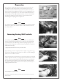
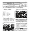
Installation Instructions
Forward Control Kit
For FXR® 1984 and newer
ATTENTION
Statements in these instructions that are preceded by the following
Important Notice
n
words are of special significance:
Before installing this forward control kit, read through these in-
structions completely; this will familiarize you with the way in which
the parts fit together and the tools needed to complete the job.
Warning
This means there is the possibility of injury to
yourself or others.
n
In the course of installing this kit you will be replacing the rear
brake master-cylinder assembly and the brake line that runs from
the master-cylinder to the brake light switch junction and then on
Caution
to the rear brake caliper. No brake lines are included in this kit, you
This means there is the possibility of
damage to the motorcycle.
must order the brake lines separately.
Note
n
Information of particular importance
has been placed in italics.
PM products are design to use both DOT 4 and DOT 5 brake
fluid, please use the manufactures suggested brake fluid. Never
reuse brake fluid, Never mix DOT 4 and DOT 5 brake fluid, don’t
use brake fluid that you are not sure is new and clean. This installation should only be attempted by a mechanic with a thorough un-
WARRANTY
derstanding of and experience with motorcycle hydraulic systems.
Performance Machine Inc. warrants to the original purchaser
that the parts of this Brake Kit to be free of manufacturing
defects in materials and workmanship for a period of one (1)
year from the date of purchase. In the event warranty service is
required,you must call Performance Machine immediately with
a description of the problem.
n
To install this kit you will be changing the shift pedal assembly. It
is highly advised to also obtain the appropriate service manual for
your motorcycle for detailed instructions regarding the transmission
shift linkage.
If it is deemed necessary for Performance Machine to make an
evaluation to determine whether the part is defective,[a return
authorization number will be given by Performance Machine].
The parts must be packaged properly so as to not cause further
damage and returned prepaid to Performance Machine with a
copy of the original invoice of purchase and a detailed letter
outlining the nature of the problem. If after the evaluation by
Performance Machine the part was found to be defective it will
be repaired or replaced at no cost to you. If we replace it,we
may replace it with a reconditioned one of the same design.
Warning
Before performing any installation steps, disconnect the motorcycles battery to eliminate any possibility of damage to yourself or
the electrical system.
n
Performance Machine shall not be held liable for any consequential or incidental damages resulting from the failure of a
Performance Machine part.
Disclaimer
Performance Machine shall have no obligation if a part becomes defective as a result of improper installation, modification or abuse.
6892 Marlin Circle, La Palma, CA 90623
Rev. 4-15-08
These Performance Machine parts are designed for high performance motorcycle applications and are intended for the very experienced rider only. The installation of these Performance Machine
parts may adversely affect or void your factory warranty.
n
Phone 714-523-3000
n
FAX 714-523-3007
Harley Davidson is a registered Trademark of the Harley Davidson Motor Company
Preparation
Before starting to assemble this forward control kit on your motor-cycle check
the packing list to make sure that the kit you received is the correct one for
your model motorcycle and that the foot pegs and foot pedals are the style you
ordered. Check the master cylinder part number, if you are installing this kit on a
motorcycle with a single caliper the 5/8” bore master cylinder P.N. 0065-2603 is
recom-mended, for a dual caliper installation then the 3/4” bore master cylinder
P.N. 0065-2703 should be used. Next check the contents hardware kit P.N.
0109-1000 against the packing list for complete-ness.
FXR FORWARD CONTROL KIT
Note
The following steps require basic knowledge of Harley® motors and more detailed
descriptions of primary case and chain removal is readily available from the factory service manuals.
Removing Factory Shift Controls
Photo 1
Note
The installation of Performance Machine Forward Controls on an FXR requires
removal of the inner and outer primary covers, as well as the clutch, compensating
sprocket and primary chain. We strongly recommend replacing the primary cover
gaskets as well as the inspection co ver gasket with new units (gaskets not included in
PM Forward Control Kit).
A spring compressor will also be necessary to remove clutch.
Photo 2
Begin by draining all oil from the primary. Remove original foot peg and foot peg
mount. Remove the shifter and outer primary cover. There are 10 bolts holding the
primary cover on. See Photos 1 and 2.
Remove chain tensioner, and starter drive gear. The starter will have to be unbolted
(from the right side of the bike ) . A spring compressor will be necessary to remove
the clutch. Unbolt the compensating sprocket and main shaft nut (leaving clutch
and compensating sprocket in place). The clutch is torqued 70-80 ft-lbs and the
compensating sprocket will be 150-165 ft-lbs from the factory and will require a
strong impact wrench to remove .
Photo 3
Note
The mainshaft nut is a left hand thread .
The clutch , compensating sprocket and chain are best removed as one unit. See
Photos 3 and 4.
Photo 4
2
Completing the Shift Control
Remove the inner primary cover and original shifter shaft and link-age. Only
the shift arm on the transmission will be left in place. The shifter shaft/arm and
linkage are no longer used. See Photo 5.
After thoroughly cleaning the inner primary cover, place it engine side up on a
flat surface and press the supplied plug into the hole left by the shifter shaft. Flip
the cover over and bolt the remaining half of the plug with the supplied button
head cap screw and a drop of L o c t i t e #242 (bl u e ) . See Photo 6.
Photo 5
Warning
Proper use of Loctite and tightening of this bolt is critical, as failure to do so could cause
serious damage to your engine.
Re-assemble the inner primary, clutch, compensating sprocket, primary chain,
chain tensioner and starter drive gear in the reverse order of removal. Consult your
factory manual for correct torque specs. PM strongly recommends you install new
gaskets at all stages of assembly.
After the outer primary cover has been installed remove the original inspection
cover and install the new cover supplied in the PM Forward Control Kit. Again,we
recommend using a new gasket. See Photo 7.
Photo 6
Installing New Shift Control
Your new Performance Machine shift controls will mount to the two hole lug
welded on your frame’s lower left side. Since these holes are generally not utilized
on an FXR you may have to run a tap through them to clean out any debris or
excess paint. See Photo 8.
Photo 7
Mount foot peg and shifter peddle to shift control assembly. Use a drop of
Loctite #271 (red) on the shifter peddle and foot peg bolts and tighten to 25 ft-lb.
Tighten the bolt while holding the footpeg pivot so that its hinge is lined up in
a 45˚ rear facing angle. At this point the footpeg itself, may not face the correct
angle (sitting on the bike your foot should be parallel to the peg). We recommend
adjusting this after both the shift and brake sides have been installed and you can
comfortably sit on the bike (see page 6 for further detail on this step).
Shift Control Assembly
Photo 8
Installing The Shift Control
Using two 3/8”x 1 1/4”socket head cap screws, with lock and flat washers, apply a
drop of Loctite #242 (blue) to threads and bolt shift assembly to frame.
See Photo 9.
Note
Before torquing the shift control mounting bolts down, tighten them
snug and look behind the shift control mounting plate to where it
contacts the mounting lug on the frame. Make sure it fits squarely to
the lug before proceeding further.
Torque the two shift control mounting bolts down to 25 ft-lb.
Photo 9
Thread the 5/16” jam nut and the 5/16” ball rod end onto the transmission shift rod
and attach it on the inside of the arm of the shift control link age using a 5/16” x
1 1/4” socket head screw, flat washer and lock nut. Attach other end of shift rod to
trans using 5/16”fine thread bolt. Mount the shift pedal to the other end of the shift
arm using a 5/16” x 1” socket head screw with a drop of Loctite #242 (blue) on it.
Adjust the transmission shift linkage until arms are parallel and secure it with the jam.
Apply a drop of Loctite #242 (blue) to the threads under the jam nut before tightening, See Photo 10. Shift pedal may not be in correct position, once linkage is secured.
Final adjustment of shift arm and brake arm are covered on page 6.
Photo 10
Setting Up the Master Cylinder
The master cylinder pushrod return spring and pushrod boot must be installed on the
master cylinder before it is assembled onto the forward control mount. The parts are
shown in Photo 11: pushrod boot (A), pushrod return spring (B), spring seat washer
(C), and master cylinder (D). Place the return spring seat washer into bore of master
cylinder so that is sits on top of the piston retaining snap ring. Next set the pushrod
return spring on the seat washer and slide the pushrod boot over the return spring
now slip the big end of the boot over the flange on the master cylinder so that the
ridge on the inside of the boot fits into groove “A” that is machined into the end of
the master cylinder flange, see Photo 12.
A
B
C
Photo 11
Installing the Brake Control
Remove the existing brake controls and lines all the way back to the caliper. Also, remove original footpegs and footpeg mounts from motorcycle. Your new Performance
Machine brake controls will mount to the two hole lug welded on your frame’s lower
right side. Since these holes are generally not utilized on an FXR you may have to run
a tap through them to clean out any debris or excess paint.
A
Photo 12
Note
For complete brake system removal instructions and precautions refer
to the appropriate service manual for your year and model.
BRAKE CONTROL
D
Installing the Brake Control Continued...
A
B
Photo 13
On the back side of Performance Machine brake control, remove the temporary assembly nut that secures the brake pedal pivot bolt. Put a drop of Loctite #242 (blue) on
the brake pedal pivot bolt “A” , fit the brake control to the mounting lug on the frame
and screw the brake pedal pivot bolt into the lower mounting hole (install the bolt
finger tight at this time), See Photo 13. Install a 3/8”x 2 1/4” hex bolt from behind the
brake pedal assembly (you will not be able to get to this bolt hole once the assembly is
mounted to the frame). See Photo 14. Next put a drop of Loctite #242 (blue) on the
3/8” x 1/2” socket head cap screw and install it through the counter bored hole at “ B
” in the brake control mounting plate and screw it into the upper hole in the mounting
lug on the frame.
Note
Before torquing the brake control mounting bolts down, tighten them
snug and look behind the brake control mounting plate to where it
contacts the mounting lug on the frame. Make sure it fits squarely to
the lug before proceeding further.
Photo 14
A
Photo 15
Torque the two brake control mounting bolts down to 25 ft-lb.
Install the master cylinder by first removing the brake pedal pushrod from the brake
pedal assembly. Next align the rear mounting hole on the master cylinder up with the
rear hole on the brake control plate and slide the master cylinder onto bolt. Apply a
drop of Loctite#242 (blue) to the bolt threads and screw the footpeg pivot onto the
bolt. Put a drop of Loctite #242 (blue) on the threads of the 3/8” x 1 1/4” socket
head cap screw and with a lock and flat washer insert it through the front mounting
hole See Photo 15, and screw it into the master cylinder, torque the bolts down to
20 ft-lb. Slip the end of the brake pedal pushrod through the hole in the end of the
master cylinder boot and into the recess in the piston and re-install to the brake pedal
using a drop of Loctite#242 (blue).
Note
Remember to hold the footpeg pivot so that its hinge is at a 45˚ rear
facing angle while the mounting bolt is tightened, See Photo 16.
See peg alignment instructions on page 6.
Adjusting The Brake Linkage
Photo 16
The master cylinder pushrod must be adjusted after the master cylinder is attached to
the brake control mounting plate. To do this you must slide the pushrod boot back
from the pedal end of the pushrod to expose the pushrod jam nut. Loosen the jam
nut and adjust the pushrod until the brake pedal has 1/8” free play, that means that the
brake pedal moves down 1/8” before the pushrod contacts the master cylinder piston.
Once the pushrod is correctly adjusted apply a dab of Loctite #242 (blue) to the pushrod threads and tighten the jam nut while holding the pushrod. After adjusting the
pushrod recheck the brake pedal’s free play, see Photo 17.
Warning
Failing to correctly adjust the brake pedal free play could cause
the caliper to lockup on the brake rotor.
Photo 17
5
Adjusting The Brake & Shifter Pedal
If you find that the brake or shifter pedal adjustment is not to your liking, you can
adjust it. You first remove the brake pedal pivot bolt, then remove the brake pedal
pinch bolt, “A” in Photo 18. Next slide the pedal off the spline shaft,“ B ”, now realign the pedal to the position you want and slip it on the spline shaft and install its
mounting bolts Re-check the brake pedal’s free play (should be 1/8”).
B
A
Aligning the Footpegs
After you have assembled the shift & brake control onto your motorcycle you must
align the footpegs. The folding footpeg assembly uses a blind stud to attach the footpeg to the footpeg pivot. Shim washers (3/8” x .015”) are used on the stud between the
footpeg and the pivot, see Photo 19, so that the top surface of the footpeg is correctly
aligned for your foot when it is tightened down on the pivot. This is done by setting a
couple of shim washers on the footpeg mounting stud “A” and then screwing the footpeg onto the mounting stud, if the footpeg is rotated to far forward then add another
shim washer, if not far enough then remove a shim washer.
After you have the selected the correct number of shims for your foot-peg, disassemble the footpeg and put a drop of Loctite #271 (red) on both ends of the stud
and reassemble the footpeg.
Photo 18
A
Photo 19
Bleeding The Brake System
Attach the brake line to the master cylinder with the supplied banjo bolt and copper
washers. Fill the master cylinder with the manufactures suggested brake fluid and set
the cover back on the master cylinder. Attach a short length of rubber hose to the
bleeder screw on the brake caliper. Pump the brake pedal several times,
see Photo 20. On the final stroke of pumping the brake pedal hold the brake pedal
down and open the bleeder fitting on the caliper, after the air and brake fluid have
stopped coming out of the hose attached to the bleeder screw it closed, you can
now release the brake pedal. This action will force the air that is trapped in the
brake system into the caliper and opening the bleeder screw, Photo 21 lets the air
out of the system. Because the brake system was empty, you will need to repeat the
bleeding procedure more than once. Check the fluid level in the master cylinder after
each bleeding, don’t let the master cylinder run dry, as this will push air back into the
brake system which will require the bleeding procedure to be started over again.
Warning
Failing to bleed all the air out of the brake system will impede
the performance of the brakes.
6
Photo 20
Photo 21
Shim Washer