1
8 Buss in-line
Recording console
PUBLICATION: AP3266
LIMITED ONE YEAR WARRANTY
This product has been manufactured in the UK by ALLEN & HEATH and
is warranted to be free from defects in materials or workmanship for
period of one year from the date of purchase by the original owner.
To ensure a high level of performance and reliability for which this
equipment has been designed and manufactured, read this User Guide
before operating.
In the event of a failure, notify and return the defective unit to ALLEN &
HEATH or its authorised agent as soon as possible for repair under
warranty subject to the following conditions:
CONDITIONS OF WARRANTY
1. The equipment has been installed and operated in accordance with
the instructions in this User Guide.
2. The equipment has not been subject to misuse either intended or
accidental, neglect, or alteration other than as described in the User
Guide or Service Manual, or approved by ALLEN & HEATH.
3. Any necessary adjustment, alteration or repair has been carried out by
ALLEN & HEATH or its authorised agent.
4. The defective unit is to be returned carriage prepaid to ALLEN &
HEATH or its authorised agent with proof of purchase.
5. Units returned should be packed to avoid transit damage.
These terms of warranty apply to UK sales. In other territories the terms
may vary according to legal requirements. Check with your ALLEN &
HEATH agent for any additional warranty which may apply.
GS3000 User Guide AP3266 Issue 2. Copyright © 1999 Allen & Heath. All rights reserved
MANUFACTURED IN ENGLAND BY:
ALLEN & HEATH
Kernick Industrial Estate
Penryn, Cornwall, TR10 9LU. UK
http://www.allen-heath.com
A DIVISION OF HARMAN INTERNATIONAL INDUSTRIES Ltd
ALLEN & HEATH AGENT:
CONTENTS
Contents ................................................................................................................. 3
Introduction, Precautions & Safety.......................................................................... 4
Key features............................................................................................................ 5
Installing the console .............................................................................................. 6
Power supply .......................................................................................................... 7
Dimensions ............................................................................................................. 8
Connections............................................................................................................ 9
Mono Input / Output channel .................................................................................. 10-12
Dual Stereo Input.................................................................................................... 13-14
Mic / Guitar Valve Input .......................................................................................... 15-16
Group / Aux Outputs ............................................................................................... 17
Studio Outputs ........................................................................................................ 18
Master & Monitor includes oscillator/talkback & 2-track mastering ......................... 19
Control Room Selection & Main L-R Outputs ......................................................... 20
The Automation System ......................................................................................... 21
Turn All Console Mutes Off or On........................................................................... 22
Mute Groups ........................................................................................................... 23
Mute Safes ............................................................................................................. 24
Mute Patches.......................................................................................................... 25
The 3 digit Patch display......................................................................................... 26-27
Solo-in-place........................................................................................................... 28
Solo Safes .............................................................................................................. 29
MIDI includes mute implementation table, channel setting & data transmission..... 30-32
MIDI Machine Control (MMC) ................................................................................. 33
Technical support includes software version, hard / soft reset ............................... 34
Error messages ...................................................................................................... 35
Front panel layout ................................................................................................... 36
Rear panel layout & Specification ........................................................................... 37
Applications – MULTITRACKING ........................................................................... 38
Applications – MIXDOWN ...................................................................................... 39
Block diagram .................................................................................... ......... rear cover
GS3000 USER GUIDE
3
INTRODUCTION
The GS3000 continues ALLEN & HEATH’s commitment to provide high quality audio mixing consoles
engineered to meet the exacting requirements of today’s audio business. It brings you the latest in high
performance technology and offers the reassurance of over two decades of console manufacture and
customer support.
This user guide presents a quick reference to the function and application of the GS3000. We
recommend that you read this guide fully before starting. For further information on the basic principles of
recording and audio system engineering, please refer to one of the specialist publications available from
book shops and audio equipment dealers.
Whilst we believe the information in this guide to be reliable, we do not assume responsibility for
inaccuracies. We also reserve the right to make changes in the interest of further product development.
SERVICE AND TECHNICAL SUPPORT
We are able to offer further product support through our world-wide network of approved dealers and
service agents. You can also access our Web site on the internet for information on our product range,
assistance with your technical queries or simply to chat about audio matters. To help us provide the most
efficient service please keep a record of the console serial number, and date and place of purchase to be
quoted in any communication regarding this product.
SAFETY WARNING!
Mains electricity is dangerous and can kill. Mains voltage is
present within the console power supply.
Do not remove the power supply cover with mains electricity
connected. To ensure your safety, mains earth is connected to
the chassis through the power lead. Do not remove this mains
earth connection.
To avoid the risk of fire, replace the mains fuse only with the
correct value and type as indicated on the power supply unit.
GENERAL PRECAUTIONS
Your GS3000 is ruggedly constructed to give many years of reliable operation. However, you will extend
the life of the console and preserve its cosmetics by applying these simple common sense precautions.
Avoid storing or using the mixing console in conditions of excessive heat or cold, or in positions where it
is likely to be subject to vibration, dust, dirt or moisture. Do not use any liquids to clean the control
surface of the console, a soft dry brush or dry lint-free cloth is ideal. Use only water or ethyl alcohol to
clean the trim and scribble strips. Other solvents may cause damage to paint or plastic parts.
The faders, switches and potentiometers are lubricated for life. The use of electrical lubricants on these
parts is not recommended.
Avoid using the console close to strong sources of electromagnetic radiation (e.g. video monitors, high
power electric cabling): this may cause degradation of the audio quality due to induced voltages in
connecting leads and chassis. For the same reason, always site the power supply away from the unit.
TRANSPORTING THE CONSOLE
The console is supplied in a strong carton. If it is necessary to move it any distance after installation it is
recommended that this packing is used to protect it. Be sure to disconnect all cabling before moving the
console. If the console is to be regularly moved we recommend that it is installed in a foamlined
flightcase. At all times avoid applying excessive force to any knobs, switches or connectors.
4
GS3000 USER GUIDE
KEY FEATURES OF THE GS3000
The GS3000 recording console offers the professional user an abundance of features with impressive
performance. It is built on the established tradition of innovative British design and manufacture. The
GS3000 is equally suited to home and studio recording. Features include:
In-line architecture for up to 32 track recording
2 independent L-R mix busses
24 and 32 channel frames
52 and 68 inputs on mixdown
8 sub groups with mono and stereo sub-grouping and bargraph meters
faders in monitor and channel paths
4 stereo input channels, 2 with full EQ and routing
2 patchable valve mic/guitar inputs channels with EQ on the guitar inputs
4 band EQ with fully parametric mids, splittable between monitor and channel paths
6 aux sends with extra stereo post-fade aux (XFX) feature for extra effects sends
impedance balanced tape send and return on every I/O channel switchable between low
level and high level (–10dBV/+4dBu)
group/direct switching on every I/O channel
LED indicator showing record ready status
Extensive talkback facility
1kHz or 10kHz oscillator for signal set up
2 studio feeds with comprehensive source selection
facility for connecting three 2-track recorders with full dubbing.
solo-in-place and PFL on both channel paths
MIDI mute automation with 128 snapshots
4 mute groups
transport controls on console using MIDI machine control
optional full length meterbridge with signal source switchable between channel or tape
return
The console is constructed using extruded aluminium beams, steel panels and 3mm thick metal side
plates. Individual circuit board assemblies are accessible by removal of the steel base. A durable soft
front armrest is provided for comfort. Armrest, channel top and rear panel write-on strips are provided for
channel marking. High quality reliable parts are used throughout. High performance op-amp and discrete
circuits are used to ensure low noise and sonic purity.
The external power supply is a silent convection cooled unit that can be rack mounted or freestanding.
The outputs are DC voltages with full protection against short circuit and over voltage.
GS3000 USER GUIDE
5
INSTALLING THE CONSOLE
Whilst great care has been taken to ensure that installations are made as trouble-free as possible, care
taken at this stage, followed by correct setting up will be rewarded by long life and reliable operation.
WIRING CONSIDERATIONS
Install separate mains outlets for the audio equipment, and feed these independently from any
other equipment such as lighting, computer and kitchen equipment.
Avoid locating mains distribution boxes near audio equipment, especially tape recorders, which are
very sensitive to electromagnetic fields.
Where possible ensure that all audio cable screens and signal earths are connected to ground only
at their source.
Avoid running audio cables next to mains, computer or lighting cables, or near thyristor
dimmer and power supply units. If unavoidable, cross these at right angles.
Use low impedance sources such as microphones rated at 200 ohms or less to reduce
susceptibility to interference. The console outputs are designed to operate at very low impedance
to minimise interference problems.
Use balanced connections where possible as these provide further immunity by cancelling out
interference that may be picked up on long cable runs. To connect an unbalanced source to a
balanced console input, link the - input (XLR pin 3 or the ring terminal of a TRS jack) to 0V earth
(XLR pin 1 or the jack sleeve terminal) at the console. To connect a balanced console output to an
unbalanced destination, link the - output to 0V earth at the console.
Use professional quality cables and connectors and check for correct wiring and reliable solder
joints.
If you are not sure ... Have your system checked by a competent engineer, or contact your local
Allen & Heath agent for advice.
EARTHING
The connection to earth (ground) in an audio system is important for two reasons:
1. SAFETY - To protect the operator from high voltage shock associated with the AC mains supply
feeding the system, and
2. OPTIMUM AUDIO PERFORMANCE - To minimise the effect of earth (ground) loops which
result in audible hum and buzz, and to shield the audio signals from interference.
For safety it is important that all equipment earths are connected to mains earth so that exposed
metal parts are prevented from carrying high voltage which can injure or even kill the operator. It is
recommended that the sound engineer check the continuity of the safety earth from all points in the
system including microphone bodies, guitar strings, multicore cases, equipment panels, etc….
For optimum audio performance it is essential for the earthing system to be clean and noise free,
as all signals are referenced to this earth. The same earth is also used to shield audio cables from
external interference such as the hum fields associated with power transformers and
electromagnetic radiation from computers. Problems arise when the signal sees more than one
path to mains earth. An ‘earth loop’ (ground loop) results causing current to flow between the
different earth paths. This condition is usually detected as a mains frequency (50/60Hz) audible
hum or buzz.
To ensure safe and trouble-free operation we recommend the following:
A central point should be decided on for the main earth point, and all earths should be individually
(‘star-fed') from this point.
For safety, the console chassis is connected to mains earth through the DC power cable and mains
power cable. Audio 0V is connected to the console chassis internally. If problems are encountered
with earth loops operate the audio ‘ground lift’ switches on connected equipment in accordance
with the operating instructions, or disconnect the cable screens at one end, usually at the
destination.
6
GS3000 USER GUIDE
POWER SUPPLY
Refer to the SAFETY WARNING on page 3 of this User Guide. Read and understand the warnings
and instructions printed on the rear panel of the power supply and reproduced here.
The power supply provided with the GS3000 is the RPS11 which is a linear supply and produces
the DC voltages required by the console. Always use the correct power supply and cable with the
console. The use of alternative supplies is not recommended and may cause damage. Check that
the correct mains lead with moulded plug has been supplied with your power supply. Ensure that
the IEC mains plug is pressed fully into the rear panel socket before switching on.
The extension of the DC power cable is not recommended and may result in the malfunction of the
mixing console.
Before switching on your console, check that the mains voltage on
the power supply unit is set to the correct mains voltage for your
area, and that the fuse is of the correct rating and type. This is
clearly marked on the rear panel of the power supply. Do not
replace the fuse with any other type, as this could become a safety
hazard and will void the warranty.
Always switch the power supply off before connecting or
disconnecting the mixer DC power cable, removing or installing
modules and servicing.
In the event of an electrical storm, or large mains voltage
fluctuations, immediately switch off the Power Supply Unit and
disconnect the mains plug from the wall socket.
It is standard practice to turn connected power amplifiers down or off before switching the console
on or off.
GS3000 USER GUIDE
7
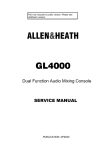
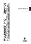
DIMENSIONS
Dimensions for installing the console and power supply unit are shown below:
RPS11 Power Supply
14.2
167.1
418.7
413.4
401.3
158.3
482.6
132.5
57.2
100.0
167.1
465.1
115.2
64.7
2.0
367.6
DIMENSIONS
Unpacked
Packed
Width
depth
height
weight(kg)
Width
depth
height weight(kg)
GS3000-824............................. 1186 ..........634 ........... 176............ 29 .......................... 1995 ..........830 ........... 330............ 38
GS3000-832............................. 1481 ..........634 ........... 176............ 37 .......................... 1995 ..........830 ........... 330............ 38
GS3000-M24 meterbridge ........ 1174 ..........56 ............. 106............ 4 ............................ 1300 ..........130 ........... 280............ 6
GS3000-M32 meterbridge ........ 1469 ..........56 ............. 106............ 5 ............................ 1600 ..........130 ........... 280............ 7
RPS11 power supply ................ 483 ............232 ........... 135............ 10 .......................... 575 ............270 ........... 170............ 11
8
GS3000 USER GUIDE
CONNECTIONS
The GS3000 uses professional grade 3-pin XLR, 1/4" TRS jack and RCA PHONO sockets. The
applications diagrams in this guide illustrate typical equipment interconnections. To ensure best
performance, we recommend that you use high quality audio cables and connectors, and take time to
check for reliable and accurate cable assembly. It is well known that most audio system failures are due
to faulty interconnecting leads.
CONNECTOR PINOUTS
CONNECTORS, CABLES AND THEORY
All input and output XLR connectors are 3-wire differentially or impedance balanced. These have 3
connector pins: pin 1 = ground 0V (cable screen), pin 2 = signal +, pin 3 = signal -.
All the master output jack connectors (e.g. Tape out, Aux out, Studio out) are 3-wire impedance
balanced. These outputs provide optimum interference rejection into the balanced inputs of
connected equipment. Jack connectors have 3 terminals: tip = signal +, ring = signal -, sleeve =
ground 0V (cable screen).
Avoid reversing + and - on balanced connections as this will result in out of phase signals (reverse
polarity) causing signal cancellation effects. This situation is particularly common in multimicrophone mixing.
Where long cables runs are required, balanced interconnections should be used. Short
interconnections between more affordable 2-wire (signal, ground) unbalanced effects units or
signal processors and mixing console may be utilised.
MIDI CONNECTIONS
Use high quality screened twist pair cable with the screen connected to pin 2 at both ends. The
cable should be no longer than 15m (50’) and terminated with 180º 5 pin male cable mount DIN
plug.
Not Used (pin 3)
MIDI In - (pin 5)
MIDI
In
Not Used (pin 2)
MIDI In + (pin 4)
Not Used (pin 1)
Not Used (pin 3)
MIDI Thru - (pin 5)
Gnd 0V - (pin 2)
MIDI Thru + (pin 4)
MIDI
Thru
Not Used (pin 1)
Not Used (pin 3)
MIDI Out - (pin 5)
Gnd 0V - (pin 2)
MIDI Out + (pin 4)
MIDI
Out
Not Used (pin 1)
Rear panel view
GS3000 USER GUIDE
9
MONO INPUT/OUTPUT CHANNEL
+ 48V
30
- 5 20
40 20
MIC
LINE
50
60 40 G A I N
- 10 10
Ø
LINE
CHAN
The mono input/output (I/O) channels are designed using a very high quality analogue
signal path to give the ultimate in high quality sound. The in-line format means that the
recording and the monitor/mixdown path are both combined in the same channel. The
recording signal path is known as the channel path and the monitor/mixdown path is
known as the monitor path.
MON
0
HF
12kHz
- 15
+ 15
0
With no jack in the TAPE IN socket, the Mic/Line signal is normalled through the monitor
path.
LF
60Hz
- 15
+ 15
+48V –selects phantom power to the XLR input.
CHAN
MON
1
LINE – selects the LINE jack input on the rear connector panel and adjusts the input
preamp for line level sensitivity. In the up position, the XLR input is selected. Both these
inputs are balanced.
Q
0.6
2
1.8kHz
F
440Hz
7.5kHz
300Hz
0
- 17
18kHz
HMF
+ 17
1
Q
0.6
GAIN – Use this control to adjust the channel input sensitivity to match the connected
source signal, -10 to -60dBu for Mic gain and +10 to -40dBu for Line gain. The console
operating level (0dBu). Press the PFL switch to check the signal without affecting the
main mix output.
2
Ø –reverses the polarity of the input signal to compensate for phase differences due to
microphone placement or incorrect wiring of input cables.
120Hz
F
30Hz
600Hz
18Hz
0
- 17
1kHz
LMF
+ 17
EQ
IN
AUX
1
0
PRE/POST
10
AUX
2
0
INSERT – The INSERT point is fixed to be PRE-EQ and follows the CHAN/MON
switching for the HF/LF EQ. i.e. if the HF/LF EQ is in the channel path so will the insert
point. If the HF/LF EQ is switched to the monitor path the INSERT point will be in the
monitor path.
10
MON
EQUALISER – The EQ consists of two separate sections; an HF/LF (High/Low
frequency) section and a fully parametric HMF/LMF (High Mid/Low Mid frequency)
section.
CHAN
AUX
3
5
0
10
AUX
4
6
0
10
XFX
C
PAN
The HF and LF bands have a shelving response which means that all frequencies
beyond the turning point frequency are affected, HF = 12kHz, LF = 60Hz. Used with the
100Hz lo-cut filter you can tailor the low frequency response exactly as you require. Each
band may boost or cut by up to +/- 15dB. The centre flat position is detented for quick
resetting. The HF and LF section is normally in the channel signal path, but can be
switched into the monitor path by pressing the CHAN/MON switch.
10
L
R
MIX
5
GRP/DIRECT
0
5
GROUP 8
MUTE
10
20
PFL
OO
PEAK
C
PAN
L
R
10
L-R
STATUS
5
MUTE
0
5
HF and LF EQ
PFL
CHAN
10
MON
1-2
20
3-4
30
5-6
7-8
OO
16
The two fully parametric swept mid frequency bands HMF and LMF have a peak/dip (bell
shaped) response which means that the maximum boost or cut occurs at the selected
(centre) frequency. The centre frequency can be swept over a wide range: HMF = 300Hz
to 18kHz, LMF = 18Hz to 1kHz. Each band may boost or cut by up to +/- 17dB. The
centre flat position is detented for quick resetting. The Q control determines the
broadness or sharpness of the EQ on the centre frequency and is continuously variable
from 0.6 for subtle changes to 2 for narrow band correction or effect. Use the mids to add
warmth or presence to the sound or to notch out problem resonances. The HMF and
LMF section is normally in the channel signal path, but can be switched into the monitor
path by pressing the CHAN/MON switch.
30
- 5 20
40 20
MIC
LINE
50
- 10 10
60 40
CHAN
MON
0
12kHz
- 15
+ 15
0
60Hz
- 15
+ 15
CHAN
MON
1
0.6
2
1.8kHz
440Hz
7.5kHz
300Hz
0
- 17
18kHz
HMF EQ
LMF EQ
+ 17
1
0.6
2
120Hz
30Hz
600Hz
18Hz
0
- 17
1kHz
100Hz lo-cut filter – Attenuates frequencies below 100Hz to reduce low frequency source
noise such as unwanted rumble. It can also be used to clean up sounds which do not
have much bass content, such as vocals and cymbals.
+ 17
EQ
IN
10 PRE/POST
0
0
10
MON
CHAN
0
10
0
10
C
L
MIX
R
100Hz lo-cut filter
GRP/DIRECT
GROUP 8
PEAK
C
L
STATUS
R
CHAN
MON
AUXILIARY SENDS – A total of 6 aux busses are available. You can set up to 6 mixes
using the 4 aux send controls.
Aux sends 1 & 2 can be switched either pre or post-fade using the GLOBAL PRE/POST
SELECT SWITCH. This affects aux sends 1 & 2 for all input channels. Normally, effects
sends are post-fade, so that the effect follows the fader level and cue feeds are Pre-Fade
so that an independent mix can be sent to the musicians. The MON/CHAN switch
sources Aux sends 1 & 2 from either the monitor signal path or the channel path.
Aux sends 3 & 4 are post-fade and can also be sourced from the channel signal path or
the monitor path by selecting the MON/CHAN switch. Aux sends 3 & 4 can also be
switched to aux busses 5 & 6 to expand the number of effects that can be used at the
same time.
EQ IN – Press to switch the EQ into the signal path. The switch affects both the HF/LF
and HMF/LMF Equalisers.
C
H
A
N
N
E
L
P
A
T
H
XFX (extra FX) – When mixing down, a separate post-fade stereo effects
send can be created by pressing the XFX and MIX B switches along with the
MIX B switch in one of the studio sections on the master panel. The output
can be fed from the Studio output jack sockets to the effects unit.
PAN – positions the channel signal within the stereo image to MIX B when
selected, or to the groups when the CHAN/MON switch above the routing
switches is in the up position. Pan fully left to route the channel signal to the
odd groups and right to route the channel signal to the even groups. The
centre position (mono image) is detented for quick resetting.
MIX B – routes the channel signal to the Mix B stereo buss.
GRP/DIRECT – In the up position the post-fade channel signal (DIRECT) is
sent to the multitrack. When pressed, the corresponding GROUP mix output
GS3000 USER GUIDE
11
30
- 5 20
40 20
MIC
LINE
50
- 10 10
60 40
CHAN
MON
0
12kHz
- 15
+ 15
0
60Hz
- 15
+ 15
CHAN
MON
1
0.6
C
H
A
N
N
E
L
P
A
T
H
is sent to the tape multitrack input. Groups 1 to 8 are repeated across the
console tape outputs e.g. group 1 is on Tape Out 1, 9, 17 & 25.
MUTE – This turns the channel signal on or off. This mute can be controlled
by the automation system. This does not affect the Pre-Fade aux sends.
PFL – Press PFL (Pre-Fade Listen) to listen to the channel Pre-Fade signal
on headphones or control room speakers. The signal level is shown on the
L and R bargraph meters.
Channel fader – 60mm smooth action fader controls the overall channel
level. All post-fade aux send levels in the channel path are dependent on
the level of the channel fader.
2
1.8kHz
440Hz
7.5kHz
300Hz
0
- 17
18kHz
+ 17
PEAK – The peak detect circuit samples the signal at various points within the channel
and monitor signal paths. The red LED illuminates when the signal is within 5dB of
clipping. Should this occur turn back the GAIN control to reduce the signal level.
1
0.6
PAN – positions the monitor signal within the stereo image to the L-R and
group mix busses when they are selected. The centre position (mono
image) is detented for quick resetting.
2
120Hz
30Hz
600Hz
18Hz
0
- 17
1kHz
+ 17
EQ
IN
10 PRE/POST
0
0
10
MON
CHAN
0
10
0
10
C
L
MIX
M
O
N
I
T
O
R
R
GRP/DIRECT
GROUP 8
P
A
T
H
L-R – routes the monitor signal to the main stereo mix for monitoring during
track laying or for mixdown to 2-track.
STATUS – This illuminates when the channel is set in record ready mode
using the MIDI machine control function.
MUTE – This turns the monitor signal on or off. This mute can be controlled
by the automation system. This does not affect the Pre-Fade aux sends.
PFL – Press PFL (Pre-Fade Listen) to listen to the Pre-Fade signal on
headphones or control room. The signal level is shown on the L and R
bargraph meters.
CHAN/MON – This is the group routing source select switch. Press to route
the monitor signal to the group busses for subgrouping during mixdown. In
the up position, the channel signal is routed to the groups for track laying.
1-2, 3-4, 5-6, 7-8 ROUTING SWITCHES – These switches route the signal
to groups. Use the pan control to route to individual groups, i.e. pan L (left)
for groups 1, 3, 5, 7 or and pan R (right) for groups 2, 4, 6, 8.
Monitor fader – 100mm smooth action fader controls the overall monitor
level. All post-fade aux send levels in the monitor path are dependent on
the level of the channel fader.
PEAK
C
L
R
STATUS
CHAN
MON
12
GS3000 USER GUIDE
DUAL STEREO INPUT CHANNEL
0
10
0
10
PRE/POST
DUAL STEREO INPUTS – Two dual stereo input channels are included as standard.
Stereo inputs 1 & 2 are fully featured with 4-band EQ, full aux and group routing,
automated mute and 100mm fader. They are ideal for stereo instruments and MIDI
sequenced sources. Stereo inputs 3 & 4 are ‘compact’ stereo inputs again with
automated muting, ideal for returning effects to the mix. The stereo channel inputs are on
separate TRS jacks.
UPPER STEREO INPUT CHANNEL
AUXILIARY SENDS – The Left and Right stereo input signals are summed to provide
aux feeds in mono.
Aux sends 1 & 2 can be switched either pre or post-fade using the GLOBAL PRE/POST
SELECT SWITCH. This affects aux sends 1 & 2 for all channels. Normally, effects sends
are post-fade, so that the effect follows the fader level and cue feeds are Pre-Fade so
that an independent mix can be sent to the musicians.
PEAK
0
ST. 3 / 4
INPUT LEVEL -10/+4 – Input level matching from the stereo source can be switched
from +4dBu (high level) to -10dBV (low level). Use PFL to check for correct level setting.
MIX
BAL – balances the stereo channel signal within the stereo image to MIX B and L-R
when selected. If the source is mono then the BAL operates as a pan control. The centre
position is detented for quick resetting.
MIX B – routes the channel signal to the Mix B stereo buss.
- 10
+ 20
0
HF
12kHz
- 15
+ 15
MF1
0
2.5kHz
- 15
+ 15
MF2
0
250Hz
- 15
+ 15
LF
0
L-R – routes the channel signal to the main stereo mix.
MUTE – This turns the channel signal on or off. This mute can be controlled by the
automation system. This does not affect the Pre-Fade aux sends.
PFL – Press PFL (Pre-Fade Listen) to listen to the channel Pre-Fade signal in stereo on
headphones or control room speakers. The signal level is shown on the L and R
bargraph meters.
60Hz
- 15
PEAK – The peak detect circuit samples the left and right signal in the channel signal
path. The red LED illuminates when the signal is within 5dB of clipping. Should this occur
check the -10/+4 switch is set correctly.
+ 15
0
10
0
10
0
10
PRE/POST
0
LOWER STEREO INPUT CHANNEL
10
ST.1 / 2
GAIN – Use this control to adjust the channel input sensitivity to match the connected
signal source (-20 to +10dBu) to the console operating level (0dBu). Press PFL to check
the signal without affecting the main mix.
EQUALISER – Shelving HF and LF and two fixed frequency peak/dip mid controls MF1
& MF2 provide 15dB of boost or cut. Use the mids to add warmth or presence to the
sound.
MIX
STATUS
Channel fader – 60mm smooth action fader controls the overall stereo channel level. All
post-fade aux send levels are dependent on the level of the fader.
PEAK
HF/LF EQ
MF1/MF2 EQ
GS3000 USER GUIDE
13
AUXILIARY SENDS – The Left and Right stereo signals are summed to provide aux
feeds in mono. You can set up to 6 mixes using the 4 aux send controls.
0
10
PRE/POST
0
Aux sends 1 & 2 can be switched either pre or post-fade using the GLOBAL
PRE/POST SELECT SWITCH. This affects aux sends 1 & 2 for all input channels.
Normally, effects sends are post-fade, so that the effect follows the fader level and cue
feeds are Pre-Fade so that an independent mix can be sent to the musicians.
10
Aux sends 3 & 4 are post-fade and post-mute. Aux sends 3 & 4 can also be switched
to aux busses 5 & 6 to expand the number of effects that can be used at the same time.
BAL – balances the stereo channel signal within the stereo image to the MIX B or L-R.
busses. The BAL control also feeds the channel signal to the odd groups (1, 3, 5, 7)
and even groups (2, 4, 6, 8), when the routing switches are pressed. The centre
position is detented for quick resetting.
MIX
MIX B – routes the channel signal to the Mix B stereo buss.
L-R – routes the channel signal to the main stereo mix.
STATUS – This LED indicator is reserved for later function.
PEAK
MUTE – This turns the channel signal on or off. This mute can be controlled by the
automation system. This does not affect the Pre-Fade aux sends.
0
- 10
PFL – Press PFL (Pre-Fade Listen) to listen to the channel Pre-Fade signal in stereo on
headphones or control room speakers. The signal level is shown on the L and R
bargraph meters.
+ 20
0
HF
12kHz
- 15
+ 15
MF1
0
2.5kHz
- 15
+ 15
MF2
0
250Hz
- 15
+ 15
LF
0
60Hz
- 15
10
1-2, 3-4, 5-6, 7-8 ROUTING SWITCHES - These switches route the stereo signal to the
groups. BAL adjusts the balance between left and right signals in the channel. For
mono sources route the signals to individual groups by rotating fully left to route the
signal to the odd groups and right to route the channel signal to the even groups.
Channel fader – 100mm smooth action fader controls the overall stereo channel level.
All post-fade aux send levels are dependent on the level of the fader.
+ 15
0
PEAK – The peak detect circuit samples the Left and Right signal in the stereo signal
path. The red LED illuminates when the signal is within 5dB of clipping. Should this
occur turn back the GAIN control to reduce the signal level.
PRE/POST
0
10
0
10
0
10
MIX
STATUS
PEAK
14
GS3000 USER GUIDE
MIC / GUITAR VALVE INPUT
Two high quality patchable SVT (symmetrical valve technology) valve mic/line pre-amps are included in
the master section. They have been designed to give a pleasing rich warm sound with a highly expressive
high frequency response and subtle compression/soft clipping when driven with high signal levels. A
valve ‘drive’ control, varies the amount of signal being amplified by the valve and a 3 colour LED indicator
illuminates green when the signal level is greater than –15dB; yellow, when the signal level is greater
than 0dB and red, when the signal level is greater than +15dB.
In mic/line amplifier mode, the double triode valve is configured differentially ('balanced' mode) in the
circuit so that one triode is amplifying the positive half-cycle of the signal and the other triode is amplifying
the negative. The advantages of this symmetrical design is that it maximises the characteristics of the
valve, slightly compressing and then soft clipping both half-cycles equally, giving a more natural
sounding, high gain, very low noise pre-amp. The 'soft clipping' characteristic ensures that only low order
harmonics are produced when the amplifier is overdriven with a high transient peak signal.
With the push of a button the valve is configured as a guitar input stage, the valve is switched to be 'single
ended' ('unbalanced' mode) which means that in true guitar amp fashion the signal is not balanced and
the non-linear overdrive characteristics of the valve are utilised. This means that the positive half cycle of
the guitar signal will distort differently to the negative half cycle when overdriven or 'cranked up to eleven'
giving lovely rich second harmonic distortion sought after by guitarists.
The GTR EQ is tailored specifically to the frequency output of most guitar pickups and can be used to
overdrive the valve at a certain frequency.
The input source, either Mic, Line or Guitar is plugged directly into the valve stage.
10
30
0
- 5 20
40 20
MIC
50
60 40
- 10 10
510Hz
1kHz
120Hz
6kHz
0
(GTR)
- 10
+ 10
+48V – selects phantom power to the XLR input.
LINE – selects the LINE jack input on the rear connector panel and adjusts the input
preamp for line level sensitivity. In the up position, the XLR MIC input is selected. Both
these inputs are balanced.
GAIN – Use this control to adjust the input sensitivity to match the connected source
(e.g. mic, line or guitar) to the console operating level (0dBu). Press the PFL switch to
check that the signal reads an average ‘0’ on the meters.
GUITAR MODE – selects the GUITAR input on the rear connector panel. This also
configures the input for a very high impedance (Hi Z) suitable for direct connection of a
guitar. A direct injection (DI) unit is not required.
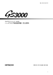
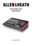
EQ – This EQ only affects the signal when guitar mode is selected. It is tuned to guitar
sound characteristics and is pre-valve so that the valve can be driven by the EQ. The
swept mid frequency band has a peak/dip (bell shaped) response, which means that the
maximum boost or cut occurs at the selected (centre) frequency. The centre frequency
can be swept over a wide range (120Hz to 6kHz) and can boost or cut by up to +/10dB. The centre flat position is detented for quick resetting.
Guitar mode EQ frequency response
0
10
Guitar mode EQ
GS3000 USER GUIDE
No EQ, HI-CUT filter in
15
Valve drive – Use this control to adjust the gain of the valve stage. This control can be used
creatively to overdrive the valve circuit and produce rich second harmonic distortion sought after by
many guitarists or the characteristic warm sound revered by vocalists.
HI-CUT – Press this switch to remove harsh high frequencies produced when overdriving the valve
circuit.
LEVEL – This control adjusts the output level from the OUT jack on the rear panel. Use this control
to compensate for the high level when the valve is overdriven and to match the signal to the normal
operating level of the channel it is patched into.
PFL – Press PFL (Pre-Fade Listen) to listen to the valve pre-output level signal on headphones or
control room speakers. The signal level is shown on the L and R bargraph meters.
PATCHING THE VALVE OUTPUT
The output of the valve channel can be patched into any console INSERT using a standard TRS
jack to jack lead.
tip = send
CHANNEL
OR BUSS
INSERT
ring = return
GS3000 rear panel
Patch lead wiring
VALVE
OUT
tip = not connected
ring = signal
16
GS3000 USER GUIDE
GROUP/AUX OUTPUT
Groups allow up to 8 separate mixes to be created and recorded on the multitrack in
addition to direct signals from the channels. Each group has a 12 segment bargraph peak
reading meter, mono/stereo switching configuration, AFL monitoring and 100mm faders.
Sometimes it is necessary to control more than one channel simultaneously, for example a
drum kit or a group of backing vocalists. This is known as subgrouping. Route the channels
to groups instead of L-R, using the channel routing switches and pan controls. PAN selects
the required group or positions the signal in the stereo image of a pair of groups.
It is normal to set up mono or stereo subgroups using the channel PAN controls and the
group L-R and STEREO switches.
The post-fade signals of the groups may be fed to the main mix L & R busses as follows:
STEREO – In the up position the groups are routed in mono to L-R. Press this switch in
association with the L-R switches below to separately route the group signal to the L or R
mix busses, L routes the odd groups e.g. 1, 3, 5, 7 and R routes the even groups e.g. 2, 4,
6, 8. This provides a stereo subgroup to L-R.
L-R – press this switch to route to the L-R mix e.g. selecting the L (left) switch of the L-R
switch pair and with the STEREO switch in the up position, the group signal will route to
both left and right mix busses. With the STEREO switch pressed, the group signal will route
to the left mix buss only.
AFL (After-Fade Listen) routes the post-fader signal to the L&R meters, the control room
speakers and the headphones and allows checking of the sound quality and mix level. If the
STEREO switch is pressed, the AFL signal will only be heard in the left or right channel
only, depending on which group has AFL selected. Pressing a pair of AFL switches allows
monitoring in stereo. If the STEREO switch is not selected then the same AFL signal will be
heard in mono.
GLOBAL
SELECT
0
10
0
AUX MASTERS
Each aux mix has a master level control that adjusts the output level to match external
equipment, or to trim the effects level without affecting the mix balance. The nominal output
level is –2dBu with an extra +10dB of boost if required. Aux 1 & 2 are switchable pre/postfade sends and 3, 4, 5 & 6 are post-fade for effects processing.
LINK – press this switch to route the aux 1 mix to aux 3, ideal for accessing a common
effect unit such as a reverb unit from both the channel path and monitor path during
mixdown.
PRE/POST GLOBAL SELECT – In the up position, the aux send is fed from the channel
Pre-Fade aux mix. Press this switch to configure Aux 1 (2) as post-fade. Normally, effects
sends are post-fade, so that the effect follows the fader level and cue feeds are Pre-Fade
so that an independent mix can be sent to the musicians.
10
MIX
0
Group fader - 100mm smooth action fader controls the overall group level. The group
outputs are routed via the GRP/DIR switches on the I/O channels to the channel Tape
outputs. Note, groups 1 to 8 outputs are duplicated on the tape outputs of I/O channels 9-16
and also on channels 17-24 and 25-32. Thus group 1 output is on the TAPE OUT jacks of
channels 1, 9, 17 and 25 when the GRP/DIR switch is pressed.
10
0
GROUPS
10
AUX – use this control to adjust the aux output level from off to +10dB.
AFL (After-Fade Listen) routes the post aux mix signal to the L&R meters, the control room
speakers and the headphones and allows checking of the sound quality and aux mix level.
The same AFL signal will be heard in both channels.
TALK – press this momentary switch to talk to the aux mix using the built-in microphone.
MUTE - This turns the Aux 5 (6) mix signal on or off. This mute can be controlled by the
automation system. This is very useful for automated effects muting.
GS3000 USER GUIDE
17
STUDIO OUTPUTS
Studio feeds 1 & 2 are stereo sub-mixed outputs which normally feed speakers or a headphone ring in
the studio providing foldback monitoring to the musicians. Aux 1 (2) can be set up as an independent
foldback mix e.g. drum mix or vocal. L-R would be the same mix as the engineers monitor mix. Press L-R
and AUX 1 (2) for a quick foldback mix created from L-R with selected signals boosted using AUX 1 (2)
sends. The CRM mix follows the engineers monitor selection e.g. use this to playback a 2-track recording
to the musicians in the studio. In mixdown, the studio outputs can be fed with a separate MIX B stereo
post-fade mix for use as an extra stereo effects send – refer to channel XFX function.
MIX
L-R, MIX B, AUX 1, CRM – pressing one or a combination of the switches selects the
source for the studio output. When more than one switch is pressed the sources mix
together.
STUDIO – use this control to adjust the studio output level.
0
10
18
MUTE - This turns the studio output on or off. It is important to mute the studio speakers
during recording or when studio microphones are live.
AFL (After-Fade Listen) routes the studio mix signal in stereo to the L&R bargraph
meters, the control room speakers and the headphones and allows checking of the
sound quality and mix level.
TALK - press this momentary switch to talk to the studio. If one or more of the source
selection switches is pressed, then the talk signal will be combined with the selection. In
this way you can communicate with the musicians and hear them via the studio
microphones.
GS3000 USER GUIDE
MASTER & MONITOR
#
#
0
10
METERBRIDGE SOURCE
"
GROUP
OUTPUT
LEVEL
The 12 segment L-R bargraph meters normally monitor the post-fade L-R mix or the
two-track return depending on the position of the 2TRK1/2/3 switches. Pressing any
PFL/AFL button on the console will override the monitor with the selected PFL/AFL
signal. A large red PFL/AFL active LED indicator illuminates to warn when a PFL or
AFL switch has been pressed.
Meterbridge source – if the optional meterbridge is fitted, press this switch to
globally switch the meters to follow the channel small fader (tape out) signal path.
When not selected the meters follow the monitor (tape in) signal path.
!
Group Output level – with the switch in the up position the nominal operating output
level for the 8 groups is +4dBu (high level). If the switch is pressed using a pen tip or
similar the nominal operating output level is –10dBV (low level). This is an underpanel
switch to prevent accidental operation.
0
10
OSCILLATOR
TALK TO GRPS
!
!
The internal sinewave oscillator provides two fixed frequencies of 1kHz and 10kHz.
The 1kHz is normally used for lining up the tape machine as the sinewave output is
routed to the group outputs. With the osc switch ON, press TALK TO GRPS and
adjust the group levels to check the line up of the connected multitrack tape machine.
The 10kHz sinewave can be used for setting the bias of an analogue tape machine,
or for checking the HF response of connected equipment.
The above procedures can also be performed for the 2 track machines by pressing,
TALK TO GRPS and then routing the signal via the group L-R switch and selecting
the 2TRK switches. Make sure the L-R meters read 0.
!
!
ALL UP= L-R
0
10
0
10
TALKBACK
A talkback mic is built into the front panel. Talkback buttons are located in various
positions in the master section to enable the engineer to talk to a number of
destinations; aux sends, mix busses, studio loudspeakers and foldback. The talkback
signal can also be routed to the multitrack for recording take information on to tape.
Press and hold these buttons for talkback. The control room speaker levels will be
dimmed to prevent feedback. The TALK LEVEL controls the talkback mic input level.
TWO TRACK MASTERING
MIX
Up to 3 two-track tape machines can be connected to the GS3000 with full dubbing
capability. The nominal operating level for Tape machine 1 (2TRK1) is +4dBu (high
level) on rear panel XLR connectors and for Tape machines 2 & 3 (2TRK2 & 2TRK3)
is -10dBV (low level) on phono connectors.
With the switches in the up position the L-R mix output is routed to all 3 Tape
machines. This is the normal position for stereo recording.
DUB 21 – routes the playback output from Tape machine 2 to the inputs of Tape
machine 1. This does not affect any other console mixing operation in progress.
DUB 12 – routes the playback output from Tape machine 1 to the inputs of Tape
machine 2. This does not affect any other console mixing operation in progress.
DUB 13 – routes the playback output from Tape machine 1 to the inputs of Tape
machine 3. This does not affect any other console mixing operation in progress.
GS3000 USER GUIDE
19
#
#
0
10
"
GROUP
OUTPUT
LEVEL
Three switches enable playback monitoring from each of the 3 tape machines.
With the switches in the up position the L-R mix output is the source.
2TRK2 – press this switch to listen to the playback from Tape machine 2.
2TRK3 – press this switch to listen to the playback from Tape machine 3.
!
10
The switch priority is 2TRK3 overrides 2TRK2 which overrides 2TRK1 which overrides
the L-R mix output to the control room. Pressing any AFL/PFL button on the console
will override the monitor with the selected AFL/PFL signal.
MONO – press this switch to combine the left and right signal. This is useful for
checking mono compatibility. This does not affect the outputs to the tape machines or
studio feeds.
PHONES - The headphone socket is located below the front armrest. Use stereo
headphones with a nominal impedance of 30 to 600 ohms and adjust the PHONES
control for a comfortable listening level.
TALK TO GRPS
!
CONTROL ROOM SELECTION
2TRK1 – press this switch to listen to the playback from Tape machine 1.
0
METERBRIDGE SOURCE
ALT – switches between the main (reference) and alternate (domestic) monitor
speakers. Useful to compare the mix between high quality studio monitor speakers
and domestic Hi-Fi speakers.
CRM – controls the level of the selected control room speakers.
SPEAKER MUTE - switches off the signal to the selected control room speakers. This
does not affect the headphone signal.
!
!
MAIN L-R OUTPUTS
!
ALL UP= L-R
0
10
0
10
MIX
MIX B TO L-R – combines the mix on the stereo MIX B busses with the main L-R mix.
This can be used during mixdown to expand the number of inputs to the mix by routing
channel path inputs to mix B.
L-R FADER – a single 100mm fader adjusts the main L-R mix level. For best
performance the faders should be operated around the ‘0’ position for normal ‘loud’
level. If you find yourself operating significantly below ‘0’ then the recorder or amplifier
input is too sensitive for the console outputs. Simply turn down the recorder or
amplifier level trim. If none is available then insert an attenuator pad between the
console and connected equipment.
20
GS3000 USER GUIDE
THE AUTOMATION SYSTEM
The GS3000 has a comprehensive automation system capable of controlling all of the large mute
switches on the console and also to remotely control the transport controls of an external machine such
as a multitrack recorder, a hard disk recorder or a MIDI sequencer.
MIDI
THE MUTE SYSTEM
HOLD FOR MIDI FUNCTION
LAST
SHIFT
HOLD FOR SHIFT FUNCTION
DUMP
MIDI
CHANNEL
ACTIVE
PATCH
AUTO
INCREMENT
AUTO
MIDI CH
The GS3000 includes a 'soft' mute system controlled by an internal microprocessor which
gives far greater control and versatility than the conventional systems found in other
consoles. A ramped FET audio element in the audio path of each channel and monitor
signal path provides silent muting under control of the microprocessor. The mutes on the
stereo input channels and aux masters 5 & 6 are also controlled by the internal
microprocessor. The red LED indicator in the mute switch always indicates the status of
the channel (illuminated = muted, off = not muted).
Operational Features
MANUAL MUTING - Press a mute switch to turn a channel on or off. The switch cap
illuminates if the channel is muted. You can also turn off (clear) or turn on (set) all the
console mutes with a single key press.
4 MUTE GROUPS - Combine selected mutes under control of a master switch. Channel
and monitor path mutes can be made 'ALL SAFE' so that they are not affected by the
groups.
128 MUTE PATCHES - Store and recall the console mute settings in numbered
patches. Includes 3 digit display, auto increment, channel and monitor 'ALL SAFE'
function.
MIDI INTERFACE - IN, OUT and THRU sockets to interface with external sequencers,
effects devices and control units. Includes MIDI machine control (MMC) to control the
transport controls of multitracks, hard disk recorder, sequencer. MIDI dump to archive and
recall console settings. MIDI note on/off messages associated with channel mutes.
SOLO-IN-PLACE - Check the contribution of individual signals within the main mix 'in
place' by pressing the associated mute switches. Includes a separate 'SAFE' facility so
that selected channels are not muted when solo is activated. The last solo setting can be
recalled for instant comparison with the mix.
CLR ALL
POWER UP AND POWER DOWN
LOC 0
The mute settings are remembered when power is removed from the console. A power
down circuit detects falling voltage and writes the settings to non-volatile memory. On
power up these settings are restored. The mute group, patch, solo safes, and mode
settings are held in similar memory.
THE MUTE SWITCH
Press MUTE once to mute the audio signal.
The red LED indicator will turn on. The audio signal will turn off (channel muted).
Mute affects the post-fade aux send signal.
Press MUTE again to turn the mute off.
HOLD +
PRESS MUTE
GS3000 USER GUIDE
21
TURN ALL CONSOLE MUTES OFF OR ON
It is often useful to turn off (clear) all the console mutes or to turn them on (set). You may wish to clear
the console before starting a new scene or setting up a new group or patch. Alternatively you could set
all mutes on and work with just the active channels. Once ’cleared’ or ‘set’ in this way you can overwrite
and edit selected groups and patches, or all 128 patches using the 'ALL' function as a starting point for a
new show.
SHIFT
HOLD FOR SHIFT FUNCTION
Turn All Console Mutes Off
Press the SHIFT + RECALL switches.
The red LED will start flashing.
The display flashes CLr
DUMP
Press any other key to cancel
or
Press the RECALL switch to confirm.
The LED will turn off.
All console mutes will turn off.
MIDI
CHANNEL
ACTIVE
PATCH
AUTO
INCREMENT
Turn All Console Mutes On
Press the SHIFT + RECALL switches.
The red LED will start flashing.
AUTO
MIDI CH
The display flashes CLr
Press the SHIFT + RECALL switch again.
The display flashes SEt
CLR ALL
Press any other key to cancel
or
Press the RECALL switch to confirm.
The LED will turn off.
All console mutes will turn on.
22
GS3000 USER GUIDE
MUTE GROUPS
A mute group lets you mute a selected combination of channels with a single key press. Applications
include muting unused channels when mixing different tracks, muting all effects, muting a group of
instruments etc...
The GS3000 includes 4 mute groups controlled by a bank of large buttons in the automation channel.
Each of the 4 mute groups can be operated either on its own or in combination with the other three. When
operated together, the mute groups effectively combine together. The mutes in the I/O channels and the
mutes in the dual stereo input channels and aux sends 5 and 6 in the master section can be included in a
mute group. Group settings can also be archived via MIDI.
Channel and/or monitor path mutes can be made ‘ALL SAFE’ to prevent them being affected by the mute
groups. They can still be operated manually.
SHIFT
HOLD FOR SHIFT FUNCTION
Program a Mute Group
Clear all console mutes.
Select the mutes to be saved in a mute group. i.e. Mute LEDs on.
DUMP
Press the STORE switch.
The 4 MUTE GROUP switches and RECALL switch will start flashing.
Press the MUTE GROUP switch to be programmed.
The STORE and RECALL LEDs will turn off.
The MUTE GROUP LEDs will be cleared.
MIDI
CHANNEL
ACTIVE
PATCH
AUTO
INCREMENT
AUTO
MIDI CH
Recall a Mute Group
Press a MUTE GROUP (1 to 4) to turn the group on.
The red LED indicates that the group is selected.
The channels programmed into the group are muted.
Press MUTE GROUP again to turn the group off.
CLR ALL
To Edit a Mute Group
Clear all console mutes.
Press the MUTE GROUP to be edited.
Press the MUTE switches to be edited.
Press the STORE switch.
The 4 MUTE GROUP switches and RECALL switch will start flashing.
Press the MUTE GROUP switch again.
The STORE and RECALL LEDs will turn off.
The MUTE GROUP LEDs will be cleared.
Factory default settings
The console is supplied with the mute groups cleared (mutes off).
This is the normal starting point for creating a new mute group.
Note that performing a hard reset restores the console to the factory default settings.
GS3000 USER GUIDE
23
MUTE SAFES
Console mutes are overwritten by mute groups, stored patches and MIDI mute data transmitted from an
external controller. The GS3000 includes a 'mute safes' facility to isolate specific groups of mutes so that
they are unaffected by the automation system.
Mute safes can be selected in 3 distinct groups:
1. All monitor path mutes in the console I/O channels. This also includes the mutes in
the stereo inputs and Aux sends 5 and 6 in the master section.
2. All channel path mutes in the console I/O channels.
3. Both together.
The mutes can still be operated manually.
These settings are automatically stored into non-volatile memory so that they are retained when power is
removed. The safes setting can be archived via MIDI.
Note that the mute safes do not affect Solo-in-place which has its own safes facility described later.
To Make the Channel path Mutes 'Safe'.
Press the CHANNEL MUTES switch in the ALL SAFE section of the automation
channel.
The LED indicator next to the CHANNEL MUTES switch will illuminate indicating
that the channel path mutes are made ‘safe’.
Press the CHANNEL MUTES switch to remove them from Mute Safe function.
Press the MONITOR MUTES switch in the ALL SAFE section to make the monitor
path mutes, the mutes in the stereo input channels and the mutes of aux sends 5
and 6 safe.
Press both switches to make all of the large mute switches safe.
24
GS3000 USER GUIDE
MUTE PATCHES
A mute patch lets you store the console mute on/off settings. Mute patches can be recalled with a single
key press. This is much like taking a 'snapshot' of the console settings. Mute patches are used
extensively during mixdown. Patch changes can be linked to external sequencers and effects devices via
MIDI for sophisticated mixdown control. Patches can be archived and recalled via MIDI.
The GS3000 includes 128 mute patch memories. The patch number is simply set up on the 3 digit
display and its contents recalled or overwritten with the current console settings. Recalling a patch does
not overwrite any active Mute Groups. Channel and/or monitor path mutes may be made 'ALL SAFE' so
that they are not affected by patch changes. Refer to the section on MUTE SAFES for details on how to
isolate the mutes .
Before starting, decide how you want to use the mute patch system. Choose the recall operating mode
with auto increment on or off.
SHIFT
HOLD FOR SHIFT FUNCTION
Select the Recall Mode
Press and hold the SHIFT switch.
DUMP
Press the AUTO switch to toggle between auto increment on/off.
Dot on = auto increment on
Dot off = auto increment off
AUTO INCREMENT ON
MIDI
CHANNEL
ACTIVE
PATCH
AUTO
INCREMENT
The display automatically increments to the next patch number each time the
RECALL switch is pressed. This lets you step through your patches without
having to press the or switches each time.
AUTO
MIDI CH
AUTO INCREMENT OFF
Press the or switches to the required patch and then press the RECALL
switch to recall the patch shown in the display.
CLR ALL
Factory default settings.
The console is supplied with all mute patches set (mutes on).
This is the normal starting point for creating mute snapshots where only active channels are on (not muted).
If you prefer to start with all patches cleared (mutes off) simply clear all console mutes and store to the ALL patch (see page 27).
Note that performing a hard reset restores the console to the factory default settings.
GS3000 USER GUIDE
25
THE 3 DIGIT PATCH DISPLAY
Normal Mode
Shows selected patch number
0 to
127
or
ALL
Indicates which patch will overwrite the console mutes when you press
RECALL, or be overwritten when you press STORE. The ACTIVE PATCH dot
tells you how the displayed number relates to the current console mute settings:
ACTIVE PATCH on :
Displayed patch is the last patch recalled. Console mutes are the same as the
displayed patch (except for channels made 'safe').
ACTIVE PATCH off :
SHIFT
HOLD FOR SHIFT FUNCTION
Displayed patch is the last patch recalled but console mutes have changed since
the patch was recalled.
ACTIVE PATCH flashing :
DUMP
Displayed patch is not the same as the last patch recalled. This is always the
case in 'auto-increment' mode where the display automatically steps up ready for
recall.
Clear or Set all Mutes
Flashes CLr or SEt to warn that all console mutes will be turned on or
off when this function is selected.
MIDI
CHANNEL
ACTIVE
PATCH
MIDI Channel Number
.1 6
The MIDI CHANNEL dot turns on to verify MIDI is selected.
AUTO
INCREMENT
AUTO
The display indicates the console MIDI channel number selected. This can be
1 to 16 or OFF
channel
MIDI CH
Software Version Number
1.2 3
Refer to the section on TECHNICAL SUPPORT.
CLR ALL
Error Codes
Displays the error number and code.
Er2
Ec1
Refer to the section on TECHNICAL SUPPORT.
Scroll Through the Patch Numbers
0 to 127 . Before
The 128 patches are numbered
patch called ALL . This is described later.
0 there is a special
Press or to increment or decrement to the required patch number. Press and
hold down or for fast scrolling to the required number.
The ACTIVE PATCH dot will indicate the status of the current console mutes
against the selected patch number.
26
GS3000 USER GUIDE
Store a Mute Patch
Select the mutes to be saved in a patch. i.e. Mute LEDs on.
Press or to the required patch number.
Press the STORE switch. The STORE LED will illuminate.
The 4 MUTE GROUP switches and RECALL switch will start flashing.
Press the RECALL switch to overwrite the patch.
The RECALL LED will flash once and the STORE LED will turn off.
The patch is now saved.
Recall a Mute Patch
SHIFT
HOLD FOR SHIFT FUNCTION
Press or to the required patch number.
Press the RECALL switch to select the patch.
The ACTIVE PATCH LED will illuminate.
DUMP
If a console mute is pressed then the ACTIVE PATCH LED will turn off as the
console mutes are not the same as the stored patch.
If the ACTIVE PATCH LED flashes, then the patch number displayed is not
the last patch recalled.
The ALL Patch
Between patch
MIDI
CHANNEL
ACTIVE
PATCH
AUTO
INCREMENT
127 and
0 is a special patch function called ALL .
This lets you overwrite all 128 patches with the current console mute settings.
You would normally do this before programming the patches for a new
recording session.
Typical applications would be:
Turn all mutes off in all patches (clear), then edit the mutes on for required
channels.
AUTO
MIDI CH
Turn all mutes on in all patches (set), then edit the mutes off for required
channels.
Turn unused channel mutes on before editing the used channels.
Turn mostly muted channel mutes on before editing the patches where they
are not muted.
CLR ALL
Note that the ALL function overwrites all 128 patches and should be
used with care. A confirm function is included to prevent accidental
operation.
Overwrite All 128 Patches
Operate the mutes to set up the console as required. You may wish to start by
clearing or setting all mutes as described previously.
Press or until the
ALL patch is displayed.
Press the STORE switch. The STORE LED will illuminate.
The 4 MUTE GROUP switches and RECALL switch will start flashing.
Press the RECALL switch. The RECALL switch flashes only.
The STORE LED will flash.
Press the RECALL switch again to confirm the all patch overwrite.
The RECALL will flash once. The patch is now saved.
GS3000 USER GUIDE
27
SOLO-IN-PLACE
Solo-in-place is a system for checking individual signals or combinations of signals in the mix. This is
done by muting all channels except for the channel/s being soloed. It is known as 'solo-in-place' because
the position and relative levels of the signal to all the outputs is retained. Solo-in-place affects the main
outputs. This should not be confused with the PFL/AFL monitoring system, which affects only the monitor
outputs. Solo-in-place is most useful during mixdown where you can listen to the contribution of
individual signals to the mix.
The GS3000 solo-in-place system lets you quickly solo selected channels. You can toggle between your
last selected solo setting and the full mix to compare the two mixes. You can make selected channels
'solo safe' to prevent them being muted when solo-in-place is activated. Typically you would solo safe the
effects returns so that the soloed channels are heard with effects. Selected mutes can be isolated (made
safe) from solo-in-place using the EDIT SAFES function. Refer to the SOLO SAFES section.
Using Solo-in-place
Press the SOLO-IN-PLACE switch. The SOLO-IN-PLACE LED flashes.
Select the MUTEs of the channels you want to solo.
If a mute in the monitor path of the I/O channels is selected then all mutes in the
monitor paths except for the selected monitor mute are turned on. Similarly, if a
mute in the channel path of the I/O channels is selected then all mutes in the
channel paths except for the selected channel mute are turned on. Press a mute
in both paths and all console mutes are turned on except for the selected
channels.
Any channel made 'solo safe' will not be affected.
You can turn on or off other mutes while in solo mode to hear the effect of
combinations of channels.
Press the SOLO-IN-PLACE switch again to exit solo mode.
LAST
This returns the console to normal mute operation. The previous mute settings
are restored.
SHIFT
Solo link
Press the SOLO LINK switch to combine the SOLO-IN-PLACE function in the
monitor and channel paths of the I/O channels i.e. pressing a mute in either path
will turn on all mutes.
HOLD FOR SHIFT FUNCTION
DUMP
Last Solo
Having set up a solo combination you may wish to compare the effect of this
with the complete mix. Instead of having to repeat the selection of the channels
as above you can recall your last solo combination. You can toggle repeatedly
between this and the mix to judge the effect.
Press the SHIFT + SOLO-IN-PLACE switches.
The last solo combination is activated.
While holding SHIFT, press and release the SOLO-IN-PLACE switch.
This toggles between the last solo and the mix.
Release the SHIFT and SOLO-IN-PLACE switches to restore normal operation.
28
GS3000 USER GUIDE
SOLO SAFES
Solo-in-place can mute all the console large mute switches which includes the monitor and channel path
mutes in the I/O channels, the dual stereo input channels, aux sends 5 and 6. To hear the effect of
soloed channels the required outputs should not be muted. You may also wish to always hear the effect
of signal processing devices such as reverbs connected to the console aux sends and returns. Here, the
aux sends and channels allocated as effects returns should not mute when solo is activated.
The GS3000 includes a 'solo safe' facility so that selected mutes can be disabled from the solo system.
This works in the same way as the 'mute safes' described earlier but affects solo and not the mute groups
or patches. Setting up solo safes should be done before the recording or mixdown session. ‘Solo safe’
settings are retained on power off and can be archived via MIDI.
Make a Channel 'Solo Safe'
Press the EDIT SAFES switch. The EDIT SAFES LED and SOLO-IN-PLACE
switch flashes.
All mutes will turn on except those already made SOLO SAFE.
Press the individual mute switches to be made safe.
Note: audio mutes are affected during SOLO SAFE editing.
Press the EDIT SAFES switch to exit 'solo safe' mode and return the console to
normal operation.
or;
Press the SOLO-IN-PLACE switch to exit 'solo safe' mode and activate solo-inplace mode.
LAST
SHIFT
HOLD FOR SHIFT FUNCTION
Channel safe
Press the CHANNEL SAFE switch to exclude the SOLO-IN-PLACE function
from all channel path mutes of the I/O channels. This prevents accidental solo
muting of the channels being recorded. The monitor mix can be soloed without
affecting the recording.
GS3000 USER GUIDE
29
MIDI
The Musical Instrument Digital Interface (MIDI) was originally conceived to standardise the
interconnection between keyboards and other instruments. It is now found on all types of equipment
including sound and lighting consoles, effects devices and computers. Sophisticated recording is now
possible by interfacing sound consoles with other MIDI equipment.
The GS3000 includes a full opto-isolated Musical Instrument Digital Interface (MIDI) system. Standard 5pin IN, OUT, THRU DIN sockets allow connection to external MIDI equipment including computers,
sequencers, data archiving systems, musical instruments and so on. The console mute system can
control or be controlled using MIDI. Applications include sophisticated 'hands-off' mute control of effects,
instrument patch control, and archiving of the mute settings for recall.
Pressing console mutes transmits MIDI Note On messages. Recalling patches transmits MIDI Program
Change messages. Similarly receiving the MIDI Note On and Program change messages overwrites the
console mutes and patches. The console mute memory can be dumped out or in using MIDI System
Exclusive messages. The console can be set to operate on any MIDI channel and if required MIDI can
also be disabled.
The MIDI Cables
Use high quality screened twisted pair cable with the screen connected to pin 2 at both ends. The cable
should be no longer than 15m (50’) and terminated with 180º 5pin male cable mount DIN plugs. MIDI
cables are available from you local audio dealer or music shop. To control external equipment, connect
the MIDI OUT of the console to the MIDI IN on the external equipment. To control the console, plug the
MIDI OUT or THRU of the external equipment to the console MIDI IN. To pass MIDI through the console
to the external equipment plug the console MIDI THRU to MIDI IN on the external equipment.
MIDI
HOLD FOR MIDI FUNCTION
Select the Console MIDI Channel
Press and hold the MIDI switch to enter 'MIDI mode'.
The display MIDI dot turns on and the current MIDI channel number is shown.
While holding the MIDI switch, use the
channel numbers (i.e. 1 to 16)
or switches to scroll through the MIDI
Release the MIDI switch when the desired MIDI channel number is displayed.
LAST
SHIFT
Disable the Console MIDI System
Press and hold the MIDI switch to enter 'MIDI mode'.
While holding the MIDI switch, use the or
channel numbers until OFF is displayed
Release the MIDI switch to exit.
HOLD FOR SHIFT FUNCTION
DUMP
MIDI
CHANNEL
ACTIVE
PATCH
AUTO
INCREMENT
AUTO
MIDI CH
CLR ALL
30
GS3000 USER GUIDE
switches to scroll through the MIDI
Channel Mutes
Pressing any console mute switch transmits a MIDI Note On
message unless MIDI has been disabled. Similarly receiving the
correct Note On message will control the channel mute unless it
has been made 'mute safe' or MIDI disabled.
Console mutes are mapped to MIDI Note numbers as shown.
Running status is supported on receive and transmit.
TRANSMIT - Pressing a console mute transmits the following
Note On message:
9n cc vv cc 00
where
n = console MIDI channel number
cc = console channel number
vv = 3FH for mute off, 7FH for mute on
RECEIVE - The console responds to the following MIDI Note
On message :
9n cc vv
( 00 is ignored)
Mute Patches
Recalling a patch will transmit a MIDI Program Change message
unless the MIDI is disabled. Similarly receiving the correct
Program Change message will recall a console patch unless
MIDI is disabled.
Console patches are directly mapped to MIDI Program Change
numbers 0 to 127. Running status is supported on receive and
transmit.
TRANSMIT and RECEIVE - The message format is :
Cn pp
where
n
pp
= console MIDI channel number
= console patch number 0-127
MIDI Dump Format
The format for Dump In and Dump Out is identical. The Dump is
made up of 128 System Exclusive messages (or packets) which
contain the contents of the console memory.
TRANSMIT and RECEIVE - The format for a single packet is
as follows :
F0 <sysex header> <packet no.> <data> <checksum> F7
<sysex header> = 00 00 1A 50 06 VV vv nn
VV
= major software version number e.g. V1.23
vv
= minor software version number e.g. V1.23
nn
= console MIDI channel number
<packet no.>
= packet number from 0 to 127
<data>
= 7 bit block of console data followed by a
number of 00 pad bytes.
<checksum>
= checksum to allow error detection.
KEY
M = Monitor path mute.
C = Channel path mute.
ST = Stereo input mute.
AX = Aux send master mute.
GS3000 USER GUIDE
31
MIDI Dump Data
When a MIDI DUMP OUT is performed the entire contents of the console
memory is transmitted down the selected MIDI channel. This includes the current
console mute settings, mute groups, patches, safe settings, solo settings,
console modes, and console MIDI channel number. When a MIDI DUMP IN is
received the console memory is completely overwritten.
This is ideal when you want to archive settings and recall them at a later date, for
example a re-run of a previous mix. You can also use the dump facility to
program other GS3000 consoles.
SHIFT
MIDI Dump Out
Press the SHIFT + STORE switches.
HOLD FOR SHIFT FUNCTION
The dump is started down the selected console MIDI channel. If MIDI has been
disabled (channel = OFF) then nothing will happen when dump is activated.
DUMP
The display flashes
dPo during the duration of the dump (around 15 seconds).
While dump is in progress the mute group and patch system is locked out.
However, the channel mutes may be operated in the normal way so that manual
operation may continue unaffected.
MIDI Dump In
The console responds automatically to the System Exclusive dump in message
formatted as above.
MIDI
CHANNEL
ACTIVE
PATCH
AUTO
INCREMENT
AUTO
MIDI CH
CLR ALL
32
While the console is receiving dump in data the display flashes
seconds).
dPI (around 10
While dump is in progress the mute group and patch system is locked out.
However, the channel mutes may be operated in the normal way so that live
operation may continue unaffected.
On completion the console restores normal operation with the new memory
settings in place.
Dump Errors
If the console or connected equipment fails to respond to a MIDI dump then
check that the MIDI is correctly enabled on each. Check that the cables are
correctly plugged. In the event of a data error being detected during a MIDI
dump out or in the display will show an error message code. Refer to the section
on TECHNICAL SUPPORT for an explanation of these.
GS3000 USER GUIDE
MIDI MACHINE CONTROL (MMC)
SHIFT
HOLD FOR SHIFT FUNCTION
The transport controls located in the automation channel of the GS3000 enables your
multitrack tape machine, hard disk recorder, VTR or MIDI sequencer to be stopped,
started, fast forwarded, rewound, marked and located and to record/replay from the
console. The GS3000 uses MIDI machine control via the MIDI connection.
MARK AND LOCATE
DUMP
The mark and locate switches enable you to electronically mark a specific point on the
tape or sequencer track and to quickly return to that position at the press of a switch.
To mark and locate a tape position.
Position the tape at the required point to be ‘marked’.
MIDI
CHANNEL
ACTIVE
PATCH
AUTO
INCREMENT
AUTO
MIDI CH
CLR ALL
Press the MARK switch to register the specific location on the tape e.g. a “drop in”
point.
When the tape has moved to a different position, press the LOCATE switch to move
the tape to the ‘marked’ position on the tape.
LOC 0 Locate 0, press and hold the SHIFT switch and then press the LOCATE
switch to rewind the tape to the 0 position of the tape i.e. usually the start of the tape.
RECORD READY
Individual tape tracks on the multitrack recorder or sequencer can be set into record
ready state from the GS3000 console.
To set tape tracks in record ready state.
Press and hold the RECORD switch.
Press the MUTE switch on the required channel corresponding to the tape track
e.g. press channel mute switches 1-8 to set tape tracks 1-8 in record ready state.
The STATUS LED indicator on each channel will illuminate to indicate the
corresponding tape track is set record ready. Note; pressing either mute in the monitor
or channel path will set the corresponding tape track in record ready state. The audio
mutes are unaffected.
Release the RECORD switch when all required tape tracks have been set.
LOC 0
To deselect tape tracks in record ready state, press and hold the RECORD switch and
press the MUTE switch to deselect the tape track corresponding to the console
channel.
To record tape tracks.
Having set all the required tracks in record ready mode, press and hold the RECORD
switch and then press the PLAY switch.
To stop recording, press the STOP switch.
If the PLAY switch is pressed again during a record sequence, the tape machine will
immediately dropped out of record and into play.
HOLD +
PRESS MUTE
GS3000 USER GUIDE
33
TECHNICAL SUPPORT
Should you have any queries about the GS3000 console automation system please quote the console
model, serial number and software version number in any communication with Allen & Heath or appointed
service agent. If a problem is encountered, check first that external equipment is correctly connected and
functioning as intended (or disconnected to test the console itself). Check the console has been correctly
set up, and that the mains power is correct for the power unit. Software error detection systems have
been built in to assist with problem investigation. Refer to the section on Error Messages.
Power Up and Power Down
The console settings are remembered when power is removed from the console. A power down circuit
detects falling voltage and writes the settings to non-volatile memory. On power up these settings are
restored. Mains power fluctuations ('brown-outs') are detected with error code readout.
MIDI
Software Version Number
Press the SHIFT + MIDI switches together.
HOLD FOR MIDI FUNCTION
The software version number is shown on the patch display. For example,
version V1.23
1.23 is
Release the keys to return to normal display.
Soft Reset
Should the system lock up and fail to clear itself first press the underpanel RESET
switch below the MIDI sockets on the rear panel. This restarts the processor as if the
console was powered off and then on, except that the console may not reset to the last
active mute settings.
Make sure the reset switch is returned to the normal out position to
restore normal operation. If left pressed, the console is held in reset
mode and the automation will remain locked.
LAST
SHIFT
HOLD FOR SHIFT FUNCTION
DUMP
Hard Reset
Should the console memory become corrupted, it can be reset to the factory defaults by
performing a hard reset :
Press and hold the EDIT SAFES + STORE switches while powering up the console.
The following default condition is reset :
All console mutes turned on.
3 digit display shows
0
All mute patches set (mutes turned on).
All mute groups cleared (mutes turned off).
MIDI
CHANNEL
ACTIVE
PATCH
AUTO
INCREMENT
MIDI channel set to
16.
No mute safes set.
AUTO
No solo safes set.
MIDI CH
CLR ALL
34
GS3000 USER GUIDE
ERROR MESSAGES
In the event of an automation error an error message is displayed. This is a two part message
comprising an error number and an error code. For example, should a MIDI Dump In error be detected
the following error number will be displayed:
En0
Press any automation key to show the error code, which gives further information about the error.
Ec1
Press any automation key to clear the error display and return the system to normal operation.
The following error messages apply:
ERROR
NUMBER (n)
ERROR
CODE (C)
DESCRIPTION
0
Press RECALL
0
1
2
3
4
MIDI Dump In error
Packet 0 not received
Missing packet
Buffer overflow
Checksum error
Dump timeout
1
Press RECALL
0
1
2
3
4
EEPROM memory access error
Write error
Page write error
Read error
Page read error
Byte read error
2
Press RECALL
Power brown-out detected
GS3000 USER GUIDE
35
FRONT PANEL LAYOUT
30
- 5 20
40 20
MIC
LINE
50
- 10 10
60 40
"
'
0
- 5 20
CHAN
MON
0
+ 15
0
60 40
- 10 10
60 40
CHAN
MON
120Hz
6kHz
%
0
1
%
+ 10
120Hz
- 17
- 10
+ 10
10
%
30Hz
10
0
1kHz
MIX
MIX
TALK TOGRPS
+ 17
EQ
IN
0
0
0
MON
CHAN
0
10
0
GROUP 8
%
%
10
0
- 10
ACTIVE
PATCH
- 15
+ 15
- 15
STATUS
CHAN
MON
R
0
10
- 15
0
PRE/POST
0
10
0
0
0
10
0
10
10
10
PRE/POST
10
& 10
0
MIX
10
STATUS
LOC 0
PEAK
!
GS3000 USER GUIDE
PEAK
%
STATUS
MIX
HOLD +
PRESS MUTE
36
+ 15
CLR ALL
10
60Hz
+ 15
MIX
LF
0
C
L
+ 15
- 15
LF
MF2
250Hz
MIDI CH
" + 15
0
60Hz
- 15
MF2
0
AUTO
MF1
2.5kHz
250Hz
+ 15
0
+ 15
0
- 15
MF1
AUTO
INCREMENT
0
HF
12kHz
+ 15
- 15
MIDI
CHANNEL
ALL UP= L-R
0
+ 20
0
2.5kHz
- 10
HF
12kHz
0
0
+ 20
0
PEAK
DUMP
- 15
&
PEAK
GRP/DIRECT
10
0
0
%
10
C
R
0
10
L
MIX
10
$
10
$
PRE/POST
10
SHIFT
HOLD FOR SHIFT FUNCTION
- 17
PEAK
LAST
!
$
0
10
MIX
600Hz
18Hz
0
#$
#
10
10
2
120Hz
PRE/POST
"
& 10
0
0
MIX
10
PRE/POST
10
10
0
0
0
10
HOLD FOR MIDI FUNCTION
0
0
MIDI
$
GROUP
OUTPUT
LEVEL
1
10
(GTR)
+ 17
0.6
0
%
18kHz
GLOBAL
SELECT
$
7.5kHz
0
0
1.8kHz
300Hz
10
6kHz
0
2
440Hz
GLOBAL
SELECT
METERBRIDGE SOURCE
1kHz
(GTR)
- 10
0
510Hz
1kHz
"
"
510Hz
+ 15
0.6
50
"
60Hz
- 15
"
40 20
MIC
50
- 10 10
10
30
0
- 5 20
40 20
MIC
12kHz
- 15
10
30
REAR PANEL LAYOUT
SPECIFICATIONS
0 dBu = 0.775 Volts rms
0 dBV = 1 Volt rms
HEADROOM:............................................................ +21dB
MAX OUTPUT:.............. ……………21dBu 2kohm max load
METERS: Groups 1-8, L, R .........peak reading 12 bar LED
PEAK LEDs: ........................... Turn on 5dB before clipping
FREQUENCY RESPONSE referred to 1kHz at +4dBu:
Any input to any output................. 20Hz to 20kHz +0/-0.5dB
DISTORTION: THD+Noise at +14dBu 1kHz
Mic in to L-R output, 40dB gain.................................0.006%
Line in to L-R output, 0dB gain .................................0.006%
CMRR
Mic in, 40dB gain at 1kHz .......................................... >80dB
CROSSTALK: Referred to driven channel at 1kHz
Adjacent channel ................................................... <-100dB
Channel fader off ..................................................... <-90dB
Channel mute on...................................................... <-75dB
Channel Pan pot isolation ....................................... < -72dB
NOISE: Measured rms 22Hz to 22kHz bandwidth
Mic input EIN (150 ohm source) ..............................<-128dB
Line preamp, 0dB gain ............................................<-93dBu
LR output residual noise..................... <-98dBu (102dB S/N)
LR faders unity mix noise .................... <-90dBu (94dB S/N)
LR mix noise (16 channels routed) ....... <-86dBu (90dB S/N)
LR mix noise (24 channels routed) ..........................<-80dBu
POWER SUPPLY: ................... RPS11 3U x 19” rack mount
AC Mains input:...................... IEC socket with lead supplied
.................................................100 to 240V AC @ 50/60Hz
...............................................set with 4 position fuse insert
Power consumption:............................................ 250W max
Mains Fuse rating:.........................100-120V AC T5A 20mm
................................................220-240V AC T3.15A 20mm
DC outputs............... ±16V @ 5A max, +48V @ 150mA max
CONNECTIONS
INPUTS:
Mic in ............................ XLR............................ pin 2 +, 3 -, balanced ... ........................ 2k ohm ............ variable -60 to +10dBu
Line in ........................... TRS jack .................... tip +, ring -, balanced ... ........................ 15k ohm .......... variable -10 to -40dBu
Stereo in (3,4) ............... TRS jack (L,R)............ tip +, ring -, balanced ... ........................ >15k ohm ........ variable -20 to +10dBu
Stereo in (1,2) ............... TRS jack .................... tip +, ring -, balanced ... ........................ >15k ohm ........ +4dBu / -10dBV switchable
Tape in .......................... TRS jack .................... tip +, ring -, balanced ... ........................ 22k ohm .......... +4dBu / -10dBV switchable
Valve Mic ..................... TRS jack .................... tip +, ring -, balanced ... ........................ 2k ohm ............variable -60 to +10dBu
Valve Line in.................. TRS jack .................... tip +, ring -, balanced ... ........................ 15k ohm .......... variable -10 to -40dBu
Valve Guitar in............... TRS jack .................... tip +, sleeve gnd, unbalanced .............. 470k ohm ........ variable +10 to -50dBu
2-Track 1 in ................... XLR............................ pin 2 +, 3 -, balanced .. ........................ >10k ohm ........+4dBu
2-Track 2&3 in............... RCA PHONO ............. unbalanced ...... ........... ........................ >10k ohm ........ -10dBV
INSERTS:
Chan, groups, L-R ......... TRS jack .................... tip send, ring return, unbal .................... <75 ohm, >7k ohm....... -2dBu
OUTPUTS:
Direct (Tape) out ........... TRS jack .................... tip +, ring -, impedance balanced .......... <75 ohm .......... -2dBu
Groups (Tape) out ......... TRS jack .................... tip +, ring -, impedance balanced .......... <75 ohm .......... +4dBu / -10dBV switchable
Valve out (½ patch) ....... TRS jack .................... ring +, tip not used, unbalanced ............ <75 ohm .......... -2dBu
Aux out......................... TRS jack .................... tip +, ring -, impedance balanced .......... <75 ohm .......... -2dBu
2- Track 1 out ................ XLR............................ pin 2 +, 3 -, ground compensated ........ <75 ohm .......... +4dBu
2-Track 2&3 out............. RCA PHONO ............. unbalanced ...... ........... ........................ <75 ohm .......... -10dBV
Studio outputs ............... TRS jack .................... tip +, ring -, impedance balanced .......... <75 ohm .......... -2dBu
Control room outputs..... TRS jack .................... tip +, ring -, impedance balanced .......... <75 ohm .......... -2dBu
Phones out .................... TRS jack .................... tip left, ring right ........... ........................ for stereo headphones 30 to 600 ohms
GS3000 USER GUIDE
37
in
thru
MIDI
3
CONTROL ROOM
main
monitors
near field
monitors
MIDI
in
2
stripe tape with timecode
or
L
Engineers
Headphones
CRM ALT
Dubbing can be performed
without affecting any other
console operation.
MMC
transport
control
Monitor
R
phones socket
under armrest
Record
to stereo input or
2 I/O channels
panned L & R
D.I.
1
MIC input
MIDI
Tape Tape
out
in
to line
input
CRM MAIN
Aux 1 & 2
studio
foldback
Aux 3 to 6
to Fx units
out
Fx returns on
stereo input
channels
Aux 1 & 2
studio foldback
STUDIO 1
Studio monitors
STUDIO
Cue Headphone ring
Musicians foldback
STUDIO 2
to Valve preamp
Guitar input
(No D.I. required)
Studio 1
cue
headphones
Aux Send 1&2
prefade for foldback
Studio 2
speaker
playback
Aux Send 3 to 6
postfade for effects
Aux 1 & 2
foldback
CHANNEL PATH
MIX B off
AUX 1
AUX 2
FX 1
from console
INSERT point
Floating EFFECT
FX 2
from console
INSERT point
Floating EFFECT
FX 3
Recording level
(to tape)
AUX 3
FX 4
MONITOR PATH
AUX 4
return to stereo
input channels
return to stereo
input channels
FX 5
return to stereo
input channels
AUX 5
FX 6
Monitor level
(from tape)
Group from channels
e.g. drums
(send to tape)
AUX 6
L-R mix =
monitor mix
return to stereo
input channels
EFFECTS & SIGNAL PROCESSORS
MULTITRACKING
SOURCES
MIDI
in
in
in
thru
in
2 TRACK MASTERING
3
Timecode
to sync
sequencer
with tape
CONTROL ROOM
main
monitors
near field
monitors
2TRK
3
2
out
MIDI SQUENCER
thru
2TRK
2
or
in
R
L
2TRK
1
SOURCES
Playback
MIDI
thru
in
VOICE
MODULE
CRM ALT
MMC
transport
control &
recorded
mutes on
sequencer
2 track
dubbing
CRM MAIN
up to 8 additional effects from groups 1-8.
Tape in
L
phones socket
under armrest
Aux 1 to 6
effects sends
R
L
Engineers
Headphones
1
VOICE
MODULE
Tape out
MIDI
out
in
R
FX 1
return to console inputs
AUX 1
Fx returns on
stereo input
channels
FX 2
AUX 2
return to console inputs
FX 3
AUX 3
MIDI
out thru
return to console inputs
FX 4
AUX 4
in
return to console inputs
FX 5
AUX 5
Extra effects
Studio 1
now XFX out
from MIX B.
Keyboard voices
controlled by sequencer
return to console inputs
FX 6
AUX 6
return to console inputs
EXTRA EFFECTS (XFX)
STUDIO 1 OUT
Mixdown 'virtual'
tracks from sequencer
through channel path
fader.
FX 7
return to console inputs
for mono
XFX
L
FX 8
return to console inputs
R
Mixdown to L-R
using Monitor faders
EFFECTS & SIGNAL PROCESSORS
Press XFX & MIX B to create 2 mono or 1
stereo effect send on mix B, if the channel
is not being used for additional input
Subgrouping from
recorded tracks and
additional inputs
additional inputs can be
mixed to L-R via the groups.
Mix B can either be used to mix additional inputs to L-R
or,
for additional stereo effects (XFX).
MIXDOWN
MIDI
GS3000 SYSTEM BLOCK DIAGRAM