1
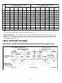
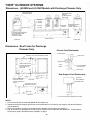
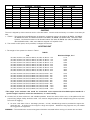
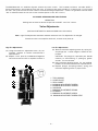
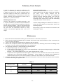
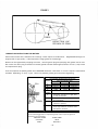
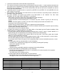
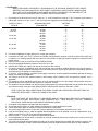
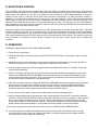
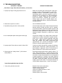
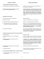
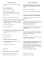
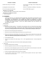
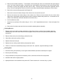
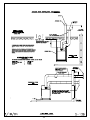
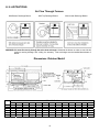
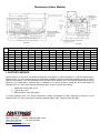
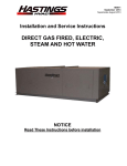
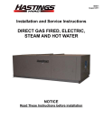
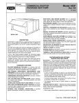
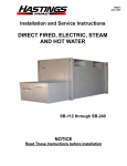
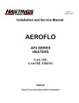
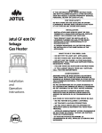
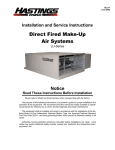
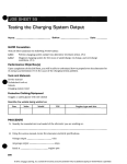
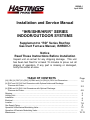
ISIRHS-1
April 2008
Installation and Service Manual
“IHR/ISHR/HR/R” SERIES
INDOOR/OUTDOOR SYSTEMS
Supplement to “RD” Series Rooftop
Gas Duct Furnace Manual, ISHRDV-1
Notice
Read These Instructions Before Installation
Inspect unit on arrival for any shipping damage. This unit
has been test fired for at least 15 minutes to prove out all
phases of operation. If any part is missing or damaged,
notify the carrier at once.
TABLE OF CONTENTS
(IH) (ISH) (H) RHF (IH) (ISH) (H) RMU and ((IH (ISH) (H) RHV Unit Dimensions.....................
(H) RHF and (H) RHV Unit Dimensions with Optional Intake and Discharge
Plenums and Curbs……………………………………………………………...........................
(H) RMU and (H) RHV Unit Dimensions with Optional Discharge
Plenums and Curbs………………………………………………………………........................
Shipping………………………………………………………………………………………………….
Hoisting Unit…………………………………………………………………………………………….
Installation……………………………………………………………………………………………….
Electrical…………………………………………………………………………………………………
Location…………..……………………………………………………………………………………...
Gas Supply Piping……...………………………………………………………………………………
Operation of Mechanical Modulating Valve………………………………………………………….
Operation of Electronic Modulating Valve……………………………………………………………
Maintenance……………………………………………………………………………………………
Page
1-2
2-3
4-5
5
5
6
6
7-8
9
10
11
12-13
(IH) (ISH) (H) RHFA - (IH) (ISH) (H) RMUA
(IH) (ISH) (H) RHVA
(IH) (ISH) (H) RHFB - (IH) (ISH) (H) RMUB
(IH) (ISH) (H) RHVB
100
125
160
210
250
300
400
600
800
200
250
320
420
500
600
800
1000
1200
A
73
80
80
83
90
90
103-1/2
110-1/2
110-1/2
113-1/2
120-1/2
120-1/2
B
30-5/8
41-3/8
52-1/8
65-1/2
131
131
30-5/8
41-3/8
52-1/8
65-1/2
131
131
C
13-3/4
13-3/4
13-3/4
13-3/4
15-1/2
15-1/2
13-3/4
13-3/4
13-3/4
13-3/4
15-1/2
15-1/2
D
19-1/2
30-1/4
41
47-3/8
113-3/8
113-1/8
19-1/2
30-1/4
41
47-3/8
113-3/8
113-3/8
E
68-1/2
75-1/2
75-1/2
78-1/2
85-5/8
85-5/8
98-7/8
105-7/8
105-7/8
108-7/8
116-1/4
116-1/4
F
17-7/8
28-5/8
39-3/8
52-3/4
114-1/2
114-1/2
17-7/8
28-5/8
39-3/8
52-3/4
114-1/2
114-1/2
G
21-7/8
32-5/8
43-3/8
56-3/8
118-5/8
118-5/8
21-7/8
32-5/8
43-3/8
56-3/8
118-5/8
118-5/8
H
14-1/4
16
19-3/8
19-7/8
19-3/8
19-7/8
14-1/4
16
19-3/8
19-7/8
19-3/8
19-7/8
J
6-1/2
11-3/4
11-3/4
6-1/2
6-1/2
6-1/2
10
11-3/4
11-3/4
6-1/2
6-1/2
10
1600
NOTES:
1. Duct dimensions are approximate. Certified prints furnished on request.
SHIPPING INFORMATION: Truck - Base unit factory assembled except for gravity vent caps and remote mounted controls.
Optional roof curb, evaporative cooling air washer section or RHFA, RMUA, RHVA 500, 600, 800 and RHFB, RMUB, RHVB
1000, 1200, 1600 Intake hood with birdscreen shipped in separate crate. Downstream duct furnaces on all 1000, 1200, 1600
models shipped in separate crate.
"HR/R" OUTDOOR SYSTEMS
Dimensions - (H) RHF and (H) RHV Models with Intake and Discharge Plenums.
FRESH AIR INTAKE WITH BIRDSCREEN
REMOVABLE PANEL FOR
DUCT CONNECTION AND
INSPECTION
REMOVABLE PANEL FOR DUCT
CONNECTION AND INSPECTION
DRAIN PAN
OPTIONAL
MIXING
DAMPERS
LOUVER
ASSEMBLY
RETURN AIR DUCT
CONNECTION - 1" FLANGES
TURNED UP
1-1/2
17-1/2
F
FLANGE AROUND
PERIMETER OF PLENUM
BASE FRAME SERVES AS
CURB COUNTER FLASHING
REAR VIEW
INLET
PLENUM
DUCT
FURNACE
BANK A
BLOWER
SECTION
D
G
E
SIDE ELEVATION
-2-
DUCT
FURNACE
BANK B
DISCHARGE AIR
DUCT CONNECTION DISCHARGE
1" FLANGE TURNED
PLENUM
UP
F
17-1/2
3/8
FRONT VIEW
Dimensions - Roof Curbs for Intake and
Discharge Plenums.
OUTLINE OF UNIT WITH PLENUMS
NOTES:
1. Inlet plenum is shown for units with mixing
dampers. This includes louver assembly,
drain pan and fresh air intake with birdscreen.
For 100% return air applications, inlet plenum
furnished without louver assembly and drain
pan. Birdscreen is replaced with cover plate.
2. Duct Furnace Bank B furnished with (H)
RHFB - (H) RHVB models only.
3. Standard flashing and mopping procedures
are recommended for curb openings and
gas and electrical roof penetrations.
4. Deck curb available to provide covered island
under complete unit with openings for supply
and return air
3/8
A
B
BLOWER SUPPORT
FURNISHED FOR
(H) RHVA 600 AND 800
AND (H) RHVB-1000
THRU 1600 MODELS
ONLY.
3/8
J
H
19-1/2
19-1/2
C
24-3/4
21-3/4
PLAN VIEW
OUTLINE OF UNIT WITH PLENUMS
BLOWER
SUPPORT
16
INLET
CURB
DISCHARGE
CURB
ROOF LINE
ELEVATION
Plenum-Curb Relationship
Rear Support-Curb Relationship
PLENUM FRAME
UNIT BASE SIDE
CHANNELS
1" INSULATION
NEOPRENE STRIP
WOOD NAILER
1/2 X 3-1/8
NEOPRENE SEALING
STRIP
CURB
FRAME
1" INSULATION
ALL PARTS SHOWN ARE FURNISHED WITH CURBS
(H) RHFB - (H) RHVA
100 & 125
160 & 210
A
20-15/16
B
24-7/16
C
74-3/4
(H) RHFB - (H) RHVB
250 & 300
400
600 & 800
200 & 250
320 & 420
31-11/16
42-7/16
35-3/16
45-15/16
81-3/4
500 & 600
800
1000 & Up
55-7/8
117-7/16
20-15/16
31-11/16
42-7/16
55-7/8
117-7/16
59-3/8
120-15/16
24-7/16
35-3/16
45-15/16
59-3/8
120-15/16
81-3/4
84-3/4
92
105-3/16
112-3/16
112-3/16
115-3/16
122-7/16
D
82
89
89
92
99-3/16
112-7/16
119-7/16
119-7/16
122-7/16
129-5/8
E
126
133
133
136
143-3/16
156-7/16
163-7/16
163-7/16
166-7/16
173-5/8
F
17-3/16
27-15/16
38-11/16
113-15/16
17-3/16
27-15/16
38-11/16
52-3/16
113-15/16
G
3/8
3/8
3/8
3/8
1/4
3/8
3/8
3/8
3/8
1/4
H
-
-
-
-
23
-
-
-
-
23
J
-
-
-
-
48
52-3/16
-
-3-
-
-
-
60
"HR/R" OUTDOOR SYSTEMS
Dimensions - (H) RMU and (H) RHV Models with Discharge Plenums Only.
FRESH AIR INTAKE
WITH BIRDSCREEN
REMOVABLE PANEL
FOR DUCT
CONNECTION AND
INSPECTION
OPTIONAL
INTAKE
DAMPER
DUCT
FURNACE
BANK A
BLOWER
SECTION
SEE NOTE 4
FLANGE AROUND PERIMETER
OF PLENUM BASE FRAME
SERVES AS CURB
COUNTER FLASHING
DUCT
FURNACE
BANK B
DISCHARGE
PLENUM
DISCHARGE AIR DUCT
CONNECTION - 1"
FLANGE TURNED UP
G
17-1/2
E
F
SIDE ELEVATION
REAR VIEW
Dimensions - Roof Curbs for Discharge
Plenums Only.
FRONT VIEW
Plenum-Curb Relationship
PLENUM FRAME
OUTLINE OF UNIT WITH DISCHARGE PLENUM
3/8
D
1" INSULATION
WOOD NAILER
REAR SUPPORTS FOR
(H) RMUA 600 AND 800 B
AND (H) RMUB-1000
THRU 1600
CURB
FRAME
A
1/2 X 3-1/8 NEOPRENE
SEALING STRIP
3/8
K
1" INSULATION
24-3/4
C
REAR SUPPORT FOR
(H) RMUA-100 THRU
400 AND (H) RMUB-600
AND 800
Rear Support-Curb Relationship
19-1/2
J
UNIT BASE
SIDE CHANNELS
PLAN VIEW
NEOPRENE STRIP
OUTLINE OF UNIT WITH
DISCHARGE PLENUM
16
ROOF LINE
DISCHARGE
CURB
3-1/2"
ELEVATION
ALL PARTS SHOWN ARE FURNISHED WITH CURBS.
NOTES:
1. Duct Furnace Bank B furnished with RMUB-RHVB models only.
2. Standard flashing and mopping procedures are recommended for curb opening, rear support, and gas and electrical
roof penetrations.
3. Deck curb available to provide covered island under complete unit with opening for supply air.
4. High air delivery may necessitate a second Fresh Air Damper and/or Intake Hood with Birdscreen. Check Pressure
Drop Chart on page 3 and Blower Motor Capability on page 4.
-4-
A
B
C
D
E
F
G
H
J
K
100 & 125
20-15/16
24-7/16
63
23-3/16
77-1/2
99-1/2
17-3/16
3/8
-
(H) RMUA – (H) RHVA
(H)
160 & 210 250 & 300
400
600 & 800 500 & 600
31-11/16
42-7/16
55-7/8
117-7/16
42-7/16
35-3/16
45-15/16 59-3/8
45-15/16
120-15/16
67
67
70
97-7/16
33-15/16 44-11/16 58-1/8
44-11/16
84-1/2
84-1/2
87-1/2
94-19/32
114-15/16
106-1/2
106-1/2 109-1/2 116-19/32 136-15/16
27-15/16 38-11/16 52-3/16 113-15/16
38-11/16
3/8
3/8
3/8
1/4
3/8
33-1/16
36
-
RMUB – (H) RHVB
800
1000 & Up
55-7/8
117-7/16
59-3/8
120-15/16
100-7/16
58-1/8
125-1/32
117-15/16
147-1/32
139-15/16
58-3/16
113-15/16
3/8
1/4
63-1/2
36
SHIPPING
The unit is shipped by either common carrier or flat bed trailer. Consult with the factory on number of sections per
load.
1. TRUCK – The intake hood with Birdscreen is shipped in a separate crate on all Outdoor (H) RHFA, (H) RMUA,
(H) RHVA-500, 600, and 800 and Outdoor (H) RHFB, (H) RMUB, (H) RHVB-1000, 1200 and 1600
systems. Downstream heaters of all Outdoor/Indoor (IH) (ISH) (H) RHFB, (IH) (ISH) (H) RMUB, (IH)
(ISH (H) RHVB-1000, 1200, and 1600 are shipped in a separate crate.
2. The remote control panel, when provided, is shipped unmounted.
HOISTING UNIT
1. The weight of the systems is shown in Table I.
TABLE I
Unit
Maximum Weight, Lbs.*
(IH)
(IH)
(IH)
(IH)
(IH)
(IH)
(IH)
(IH)
(IH)
(ISH)
(ISH)
(ISH)
(ISH)
(ISH)
(ISH)
(ISH)
(ISH)
(ISH)
(H)
(H)
(H)
(H)
(H)
(H)
(H)
(H)
(H)
RHFA,
RHFA,
RHFA,
RHFA,
RHFA,
RHFA,
RHFA,
RHFA,
RHFA,
(IH)
(IH)
(IH)
(IH)
(IH)
(IH)
(IH)
(IH)
(IH)
(ISH)
(ISH)
(ISH)
(ISH)
(ISH)
(ISH)
(ISH)
(ISH)
(ISH)
(H)
(H)
(H)
(H)
(H)
(H)
(H)
(H)
(H)
RMUA,
RMUA,
RMUA,
RMUA,
RMUA,
RMUA,
RMUA,
RMUA,
RMUA,
(IH)
(IH)
(IH)
(IH)
(IH)
(IH)
(IH)
(IH)
(IH)
(ISH)
(ISH)
(ISH)
(ISH)
(ISH)
(ISH)
(ISH)
(ISH)
(ISH)
(H)
(H)
(H)
(H)
(H)
(H)
(H)
(H)
(H)
RHVA
RHVA
RHVA
RHVA
RHVA
RHVA
RHVA
RHVA
RHVA
(IH)
(IH)
(IH)
(IH)
(IH)
(IH)
(IH)
(IH)
(IH)
(IH)
(ISH)
(ISH)
(ISH)
(ISH)
(ISH)
(ISH)
(ISH)
(ISH)
(ISH)
(ISH)
(H)
(H)
(H)
(H)
(H)
(H)
(H)
(H)
(H)
(H)
RHFB,
RHFB,
RHFB,
RHFB,
RHFB,
RHFB,
RHFB,
RHFB,
RHFB,
RHFB,
(IH)
(IH)
(IH)
(IH)
(IH)
(IH)
(IH)
(IH)
(IH)
(IH)
(ISH)
(ISH)
(ISH)
(ISH)
(ISH)
(ISH)
(ISH)
(ISH)
(ISH)
(ISH)
(H)
(H)
(H)
(H)
(H)
(H)
(H)
(H)
(H)
(H)
RMUB,
RMUB,
RMUB,
RMUB,
RMUB,
RMUB,
RMUB,
RMUB,
RMUB,
RMUB,
(IH)
(IH)
(IH)
(IH)
(IH)
(IH)
(IH)
(IH)
(IH)
(IH)
(ISH)
(ISH)
(ISH)
(ISH)
(ISH)
(ISH)
(ISH)
(ISH)
(ISH)
(ISH)
(H)
(H)
(H)
(H)
(H)
(H)
(H)
(H)
(H)
(H)
RHVB
RHVB
RHVB
RHVB
RHVB
RHVB
RHVB
RHVB
RHVB
RHVB
–
–
–
–
–
–
–
–
–
–
–
–
–
–
–
–
–
–
–
100
125
160
210
250
300
400
600
800
1115
1155
1200
1285
1560
1625
1840
3350
3880
200
250
320
420
500
600
800
1000
1200
1600
1445
1525
1610
1800
2025
2125
2545
4520
4800
5765
*This weight is the maximum that would be encountered on the system with all available options installed. If a
specific weight is required, contact the manufacturer, or consult catalog.
2. At least four (4) lines (minimum) and suitable spreaders should be used to lift the unit, or flat platform lift with
proper lifting weight ability should be used. Unit must be slinged properly with multiple lifting points to prevent
the unit from sagging.
3. On units with either inlet or discharge plenums, or both, suitable slings must be provided for support beneath the unit. A minimum of four support slings are required. Additional sling supports may be needed
for long pieces of equipment.
WARNING – The mechanical or structural engineer should be contacted before moving unit across the roof deck.
5
INSTALLATION
1. The unit may be installed on a field fabricated mounting frame or support, a factory roof curb mounting frame or
a slab. The following items are important in this regard:
A. Be sure that roof joist or support will not interfere with discharge and return air ducts.
B. Be sure frame or support is square, level and not twisted.
C. Field fabricated frame, support, or slab must be high enough to prevent any form of moisture from entering unit.
D. All joints on frame must be sealed with caulking compound.
E. Field fabricated curb should be insulated with at least 1 ½” thick rigid type insulation.
F. The roof curb should be counterflashed and sealed before unit is installed.
2. The discharge and return air duct (if required) should be correctly sized for securing to factory installed plenums,
when provided, or to unit. Duct connection(s) exposed to the weather must be watertight. A weathertight seal
must be provided where duct(s) comes through the roof.
WARNING
1. Field Installed ductwork on the unit discharge end must be secured to the flanges on the heat exchanger and
not on unit front cabinet. Failure to properly install could cause fire, explosion, damage to equipment or even
death.
2. Installer/Service Technician must remove burner tray to inspect burner assemblies, to insure proper alignment.
Disconnect gas supply line to unit gas inlet, remove the “L” locking bracket and disconnect the electrical
connections and slide the burner tray out of the heater. Once inspection is completed, replace the burner tray
assembly and install the “L” locking bracket. Failure to perform this inspection could result in fire, explosion,
loss of warranty, or even death.
Installation of this appliance must conform to applicable federal, state, and local codes and regulations, and with
guidelines established by A.G.A. (American Gas Association), NFPA (National Fire Protection Association), N.E.C.
(National Electrical Code), the National Board of Fire Underwriters and CAN/CGA B149. Listed are the codes
appearing in this text, the Associations, and their addresses where they may be obtained.
1.
The National Fuel Gas Code
Contact American Gas Association (Administrative)
1515 Wilson Boulevard
Arlington, Virginia 22209
2.
All NFPA codes, National Electrical Code
Contact: National Fire Protection Association, Inc.
Batterymarch Park
Quincy, Massachusetts 02269
3.
Standard of National Board of Fire Underwriters
Contact: National Board of Fire Underwriters
85 John Street
New York, New York 10036
4.
Canadian Gas Association
Contact: Canadian Gas Association
178 Rexdale Boulevard
Etobicoke, Ontario, Canada M9W 1R3
ELECTRICAL
1. Unit must be electrically grounded and all wiring must be done in accordance with applicable local codes and the
National Electrical Code.
2. In order to determine the size of the power supply lines, check the electrical specification plate located on the
unit for ampere requirements.
3. On units not ordered with a disconnect switch, it is recommended that a weatherproof disconnect switch be
mounted on or near the unit.
4. Connect power supply lines from main disconnect switch to unit disconnect switch.
5. Install thermostat (RHF and RHV only) or remote control station if supplied according to wiring diagram.
6. Thermostats and remote control stations must be installed in a suitably protected and secure location to prelude
tampering and damage. Thermostats must not be exposed to physical shocks or jarring either before or after
installation.
-6-
LOCATION
NOTE: AMERICAN INSTALLATIONS MUST CONFORM WITH THE NATIONAL FUEL GAS CODE
(AMERICAN NATIONAL STANDARD ANSI Z223.1 - “Latest Revisions”) AND ALL APPLICABLE
GOVERNING BUILDING CODES. CANADIAN INSTALLATIONS MUST CONFORM WITH CAN/CGA
B149 - “Latest Revisions.”
1. The (I) (IS) HRDV Furnace has been designed for INDOOR OR HRDV FOR OUTDOOR INSTALLATIONS.
2. Refer to items 1, 2, 5, 6, 9, 10 12, 15, and 16 of INSTALLATION PRECAUTIONS.
3. REQUIRED MINIMUM CLEARANCES to combustible material are as follows:
CLEARANCES/INSTALLATION
Outdoor Models
The minimum clearances from combustible material are as follows:
Control Side – Width of Unit
Opposite Control Side – 6 inches (18” recommended for servicing)
Top of Unit – Unobstructed
Discharge and Return Air Sides – 12 inches
Bottom – 0 inches
For installation downstream from refrigeration systems.
CLEARANCES/INSTALLATIION
Indoor Models
The minimum clearances from combustible material are as follows:
Control Side – Width of Unit
Opposite Control Side – 6 inches (18” recommended for servicing)
Top of Unit – 6 inches
Discharge and Return Air Sides – 12 inches
Bottom – 0 inches
For installation downstream from refrigeration systems.
* See section on ILLUSTRATIONS for dimensions of individual furnaces.
4. Install in airplane hangars in accordance with the current ANSI/NFPA 409 - “Latest Revisions”, Standard on
Aircraft Hangars, and in public garages in accordance with the current ANSI/NFFPA BB - “Latest Revisions”,
Standards for Garages, and with CANI-B149 Codes. A clearance of 10 feet must be provided from the bottom
of the heater to the top surface of wings or engine enclosures of the highest aircraft to be housed in the hangar
and a minimum clearance of 8 feet from the door in other sections such as offices and shops connected with
hangar and in public garages. Also, the heaters must be so located that they will be protected from damage by
aircraft, cranes, scaffolding, etc., and must be accessible for servicing and adjustment. Standard ANSI/NFPA
88 - “Latest revisions” specifies that the heater must be so located that the clearance to combustible materials
conform with NFPA Nos. 52 and 54 and that such material must not attain a temperature over 160º by
continued operation of the heater.
5. If two furnaces are to be used in a side by side application, they must be installed so that the ENDS OPPOSITE
the control access doors ADJOIN.
6. A 4-inch frame is an integral part of the appliance and may be installed directly on the floor or roof or other
combustible construction. For ease of service and safe operation, however, it is suggested that the furnace be
located above the installation surface on a field fabricated base and should be high enough to prevent any form
of moisture from entering the unit.
7. Be sure that the roof joists or other obstructions will not interfere with the discharge and return air ducts.
8. The discharge and return air ducts should be correctly sized for securing to the furnace and all connections
exposed to the weather must be moisture tight. A high temperature caulking (250ºF) or sheet metal flashing
may be used for this purpose. A weathertight seal must be provided where ducts enter through the roof. Field
installed ductwork on the unit discharge end must be secured to the flanges on the heat exchanger and not on
unit front cabinet. Failure to properly install could cause fire, explosion, damage to equipment or even death.
9. Provide tight fitting inspection panels in duct work both upstream and downstream close to the furnace. These
panels must be large enough so that the heat exchanger can be easily inspected.
7
Venting:
1. The (I) (IS) HRDV model furnace is equipped with a power venter and is complete as received.
2. No further venting of unit is required for outdoor installation (HRDV).
3. Venting is required on all indoor installations ISHRDV, and IHRDV units.
a. Positive pressure flue vent is recommended for installations inside building. Provide for the ISHRDV and
IHRDV Series. For the requirement of positive pressure flue vent, review local codes.
b. Pitch vent pipe up toward outlet, ¼” per foot for condensate drainage.
c. Type “B” gas vent is recommended for flue venting above roof lines or external wall penetrations.
d. Straight vertical runs out through the roof are preferred. Vertical stack must be a minimum of five feet
high.
e. Vertical flue stacks shall be terminated with an approved cap.
f. The maximum horizontal vent pipe length for these heaters is shown in table II. A total equivalent horizontal
vent pipe length can be calculated using equivalent straight pipe lengths for tees and elbows reducing the
maximum horizontal vent pipe length by six feet for each sweep elbow, two and one half feet for
termination tee, and ten feet for each short radius elbow.
g. A gradually tapered vent pipe transition is required for (I)ISHRDV-100, (I)ISHRDV-125, and (I)ISHRDV-160
units when using 4 inch vent pipe.
h. When possible, locate horizontal vent hoods that do not face the direction of prevailing winds to diminish
the possibility of back draft situations.
i. For U.S.A. standards vent systems must conform to the latest edition of the National Fuel Gas Code
(NFPA#54) and the latest edition of NFPA #211, or as follows:
· Not less than 7 feet above grade when located adjacent to public walk ways.
· AT least 3 feet above any forced air inlet located within 10 feet.
· At least 4 feet below, 4 feet horizontally from or 1 foot above any door, window or gravity air inlet into
any building.
· At least 1 foot above grade, or at least 1 foot above the normally expected snow accumulation level.
· Directed such as to not jeopardize people.
· At least 4 feet from electric meters, gas meters, regulators and relief equipment.
· Sealing or shielding of exposed surfaces with a corrosion resistant material may be required to prevent
staining or deterioration of building materials, and
· Not less than 2 feet from an adjacent building.
j. In Canada vent systems must conform to the latest edition of the Natural gas and Propane Installation Code
(CAN/CGA-B149.1 or CAN/CGA-B149.2), or as follows:
· A venting system shall not terminate underneath a veranda, porch, or deck, or above a paved sidewalk
or a paved driveway that is located between two buildings, and that serves both buildings.
· The exit terminals of mechanical draft systems shall not be less than 2.14m above grade when located
adjacent to a paved sidewalk or driveway.
· A venting system shall not direct flue gases towards brickwork, siding, or other construction, in such a
manner that may cause damage from heat or condensate from the flue gases.
· A vent system shall not direct flue gases so as to jeopardize people, overheat combustible structures, or
enter buildings.
· A venting system shall not terminate within 1.8m of the following:
· A window, door or mechanical air supply inlet of any building, including soffit openings.
· A gas service regulator vent outlet.
· A combustion air inlet.
· A property line.
· A direction facing combustible materials or openings of surrounding buildings
· A venting system shall not terminate within 1m of the following:
· Above a gas meter/regulator assembly within 1m horizontally of the vertical centerline of the regulator.
· An oil tank or an oil tankfill inlet.
· The inside corner of an L-shaped structure.
· A venting system shall not terminate within .3m of the following:
· Above grade level or any surface that may support snow, ice, or debris.
8
Unit Type
I(S)HRDV-100
I(S)HRDV-125
I(S)HRDV-160
I(S)HRDV-210
I(S)HRDV-250
I(S)HRDV-300
I(S)HRDV-400
I(S)HRDV HORIZONTAL FLUE SIZING
Flue Pipe Diameter
4.0 IN
4.0 IN
4.0 IN
6.0 IN
6.0 IN
6.0 IN
6.0 IN
Table II
Maximum Length of Flue Pipe
82.0 FT
82.0 FT
82.0 FT
72.0 FT
72.0 FT
72.0 FT
72.0 FT
Gas Supply Piping
Suggested pipe sizing for direct line from meter or propane tank is found in Table III. These sizes are based on 6” to
7” w.c. pressure at the meter for natural gas; 11” w.c. for propane gas, with .3” w.c. pressure drop schedule 40
pipe and fittings.
TABLE III
Input in 1000’s
BTU Hr.
100 to125
150 to 175
200 to 250
300
400 to 420
500
600
800
1000
1200
1600
Maximum Distance
from Meter
50 feet
100 feet
60 feet
100 feet
30 feet
120 feet
250 feet
75 feet
200 feet
50 feet
100 feet
35 feet
80 feet
300 feet
50 feet
200 feet
30 feet
125 feet
80 feet
200 feet
50 feet
150 feet
30 feet
80 feet
250 feet
Natural*
Propane*
¾”
1”
1”
1 ¼”
1”
1¼”
1½”
1¼”
1½”
1¼”
1½”
1 ¼”
1 ½”
2”
1½”
2”
1½”
2”
2”
2½”
2”
2½”
2”
2½”
3”
½”
¾”
¾”
1”
¾”
1”
1¼”
1”
1¼”
1”
1¼”
1 ¼”
1 ¼”
2”
1¼”
2”
1¼”
2”
2”
2”
2”
2¼”
2”
2½”
3”
The BTU input and output of these systems are listed in Table IV. See page 10.
*On units receiving inlet gas pressure in excess of 14” w.c., a high gas pressure regulator must be provided for
each heater section.
9
100
125
160
210
250
300
400
600
800
TABLE IV
BTU/Hr. Input
per Heater
100,000
125,000
160,000
210,000
250,000
300,000
400,000
300,000
400,000
Total BTU/Hr.
Input
100,000
125,000
160,000
210,000
250,000
300,000
400,000
600,000
800,000
200
250
320
420
500
600
800
1000
1200
1600
100,000
125,000
160,000
210,000
250,000
300,000
400,000
250,000
300,000
400,000
200,000
250,000
320,000
420,000
500,000
600,000
800,000
1,000,000
1,200,000
1,600,000
Unit
(IH)
(IH)
(IH)
(IH)
(IH)
(IH)
(IH)
(IH)
(IH)
(ISH)
(ISH)
(ISH)
(ISH)
(ISH)
(ISH)
(ISH)
(ISH)
(ISH)
(H)
(H)
(H)
(H)
(H)
(H)
(H)
(H)
(H)
RHFA,
RHFA,
RHFA,
RHFA,
RHFA,
RHFA,
RHFA,
RHFA,
RHFA,
RMUA,
RMUA,
RMUA,
RMUA,
RMUA,
RMUA,
RMUA,
RMUA,
RMUA,
RHVA
RHVA
RHVA
RHVA
RHVA
RHVA
RHVA
RHVA
RHVA
(IH)
(IH)
(IH)
(IH)
(IH)
(IH)
(IH)
(IH)
(IH)
(IH)
(ISH)
(ISH)
(ISH)
(ISH)
(ISH)
(ISH)
(ISH)
(ISH)
(ISH)
(ISH)
(H)
(H)
(H)
(H)
(H)
(H)
(H)
(H)
(H)
(H)
RHFB,
RHFB,
RHFB,
RHFB,
RHFB,
RHFB,
RHFB,
RHFB,
RHFB,
RHFB,
RMUB,
RMUB,
RMUB,
RMUB,
RMUB,
RMUB,
RMUB,
RMUB,
RMUB,
RMUB,
RHVB
RHVB
RHVB
RHVB
RHVB
RHVB
RHVB
RHVB
RHVB
RHVB
–
–
–
–
–
–
–
–
–
–
–
–
–
–
–
–
–
–
–
Total BTU/Hr.*
Output
76,000 (80,000)
95,000 (100,000)
121,600 (128,000)
159,600 (168,000)
190,000 (200,000)
228,000 (240,000)
304,000 (320,000)
456,000 (480,000)
608,000 (640,000)
152,000
190,000
243,200
319,200
380,000
456,000
608,000
760,000
912,000
1,216,000
(160,000)
(200,000)
(296,000)
(336.000)
(400,000)
(480,000)
(640,000)
(800,000)
(960,000)
(1,280,000)
* All IH, ISH and H series units are 80% efficient
Honeywell Modusnap Valve
Model Size: 400
Temperature Settings of Controls
(Modusnap Valve, TL and DC)
(TL) SET THIS CONTROL TO 110 DEGREES, THERE IS NO OTHER SETTING ADJUSTMENT.
(This control is to protect the modusnap valve bulb from exceeding 120 degrees.)
(DC) SET THIS CONTROL TO 2 TO 3 DEGREES ABOVE MODUSNAP VALVE SETTING.
(MODUSNAP VALVE) SET THIS CONTROL 2 TO 3 DEGREES ABOVE ROOM THERMOSTAT SET POINT.
(This is to allow for temperature loss through duct work and room loss.)
MODUSNAP VALVE SETTINGS
Dial #
Degrees
1
60
2
65
3
70
4
75
5
80
6
85
7
90
8
95
9
100
(ROOM THERMOSTAT) SET AT ANY TEMPERATURE OCCUPANT WANTS, JUST SO LONG AS THE MODUSNAP
VALVE IS SET PROPERLY.
OPERATION
When the unit is in the winter mode, the fan is on bringing outside air into the building. The furnace is on and the
modusnap valve is set at 73 degrees (room set a 70 degrees – example), the modusnap valve is modulating at this
point maintaining the discharge of 73 degrees. When the room thermostat calls for more heat, the bypass valve
opens and full rate of gas is supplied to burner for full heat until the room thermostat is satisfied. (NOTE: In the
event the discharge temperature gets up to 110 degrees, the “TL” will cycle the bypass valve during the room
override mode.) When the room thermostat is satisfied, the furnace will return to discharge temperature of 73
degrees when the heat exchanger cools down from the high fire condition.
10
The 400 Model has an additional bypass without any valve control. This is called a minimum rate tube (M.R.T.).
During mild weather, the modusnap valve will cycle on minimum flow while the M.R.T. is flowing gas. For its control
the "DC" will cycle the main shut off valves to maintain discharge temperature. (There is no gas flow to burner when
"DC" is satisfied unless the unit has a room override option on the "DC" circuit.)
ALL MODEL SIZES SMALLER THAN THE 400
OPERATION:
Settings are the same as above except less the M.R.T. and "DC" control.
Valve Adjustments
(See bulletin MT2035 for additional M/MR valve information)
Note: High Fire Adjustment should be checked whenever Low Fire Adjustment is changed.
Disconnect wire from amplifier terminal 3, remove cover plate (2).
High Fire Adjustments:
Low Fire Adjustments:
(A) Using the maximum adjustment screw (4), set
manifold pressure to furnace manufacturer's
specifications.
(B) Replace cover plate (2) on Modulator-Regulator
valve and reconnect wire to amplifier terminal 3.
(A) Remove maximum adjusting screw (4), spring (5),
and plunger (8). A small magnet is useful for this
purpose.
CAUTION: The plunger is a precision part. Handle
carefully to avoid marring or picking up grease
and dirt. Do not lubricate.
(B) Using minimum adjusting screw (9), set manifold
pressure to furnace manufacturer's specifications.
(C) Replace plunger and spring retainer, spring, and
maximum adjusting screw in proper order.
2
3
1
10
4
5
9
8
7
6
1. TOP HOUSING
2. COVER PLATE
3. SEAL GASKET
4. MAXIMUM ADJUSTMENT SCREW
5. MAXIMUM ADJUSTMENT SPRING
6. SOLENOID
7. MINIMUM ADJUSTMENT SPRING
8. PLUNGER
9. MINIMUM ADJUSTMENT SCREW
10. MINIMUM ADJUSTMENT SCREW STOP
- 11 -
Preliminary Circuit Analysis
In order to diagnose the cause of problems in this
system, it is necessary to determine certain values. It
is helpful to have an AC and DC voltmeter and an
ohmmeter capable of reading 0 to 15,000 ohms. For
ease in troubleshooting, it is necessary to rewire the
system, replacing the discharge air sensor with a
4500 ohm, ½ watt test resistor.
Modulating Function Test:
Connect a DC voltmeter to amplifier terminals 1 and
2. If more convenient, the meter may be attached to
the MR valve terminals. Rotate temperature selection
knob to maximum setting – the DC volts should read
zero. The voltage should gradually increase to at least
20 volts when the temperature selector is slowly
rotated to its minimum (generally over a 3º to 4º
range).
Automatic Valve Function:
After the electronic modulation function is tested, a
voltage reading must be taken across the automatic
gas valve. These voltage readings will be
approximately 24 V AC with the temperature
selection knob at maximum setting, zero volts AC
with the selector at minimum setting. The relay
switching action should occur when the modulating
voltage is between 15 and 19V DC.
If these voltage readings are observed as noted, it is
proved that the amplifier and temperature selector are
operating properly.
After testing, remove the resistor and reconnect the
discharge air sensor.
Maintenance
1. Motors should be relubricated according to the manufacturer’s lubrication instructions.
2. Filters must be cleaned (cleanable type) or replaced (throw-away type) with like filters as often as necessary so
as not to restrict air delivery.
3. Twice a year check belts and sheaves for alignment and belt tension.
4. When a belt is replaced, shorten center distance between sheaves by loosening motor bolts and sliding motor
on support. On units requiring multiple belts, use a matched set.
5. The following procedure is recommended for tensioning belts:
A. Measure span length “X” shown in Figure I.
B. At the center of span length “X”, apply a force perpendicular to the span and large enough to deflect belt
1/64” for each inch of span length.
Example – The required deflection for a 40” span would be 40/64” or 5/8”.
C. Compare the force applied with the values given in Table V. If force is between the minimum and maximum
range shown, the drive tension should be satisfactory. A force below the minimum value indicates an
undertensioned belt and a force that exceeds the maximum value indicates an overtensioned belt.
6. Lubricate main fan bearing with a high grade lithium base grease. Perform at least every quarter (three months)
or schedule according to equipment use.
TABLE V
Belt Cross Section
(marked on belt)
A
B
Motor Pulley Pitch
Diameter
3.0” – 3.6”
3.8” – 4..8”
5.0”- 7.0”
3.4” – 4.2”
4.4” – 5.6”
5.8” – 8.6”
Deflection Force
Minimum
Maximum
2.62 lbs.
3.25 lbs.
3 lbs.
4 lbs.
3.25 lbs.
5 lbs.
3 lbs.
5 lbs.
4 lbs.
5.87 lbs.
5.25 lbs.
7.87 lbs.
- 12 -
FIGURE I
FORCE
DEFLECTION 1/64"
PER INCH OF SPAN
LUBRICATION INSTRUCTIONS FOR MOTORS
Some small motors have sealed-for-life bearings which require no relubrication. Regreasable bearings are
shipped with a high quality, wide temperature range grease in the bearings.
Motors can be regreased by stopping the motor, removing drain plug and pumping new grease into fill hole.
Run motor with drain plug removed until excess grease has been discharged (minimum 10 min.). Stop motor
and replace drain plug.
Units that operate at speeds greater than 1800 RPM should be lubricated on a more frequent maintenance
schedule depending on duty cycle. Use a low pressure grease gun and avoid overgreasing.
FILL
DRAIN
SUGGESTED REGREASING INTERVALS
SERVICE
MOTOR HORSEPOWER
UNDER 50
50-100
100 UP
A
3-5 Yrs.
2-4 Yrs.
2 Yrs.
B
2-4 Yrs.
1-1/2 Yrs. 1-1/2 Yrs.
C
1-2 Yrs.
1 Yr.
6 Mos.
D
4 Mos.
4 Mos.
3 Mos.
SERVICE
TYPE OF SERVICE
SYMBOL
A
Infrequent operation or light duty
in clean atmosphere.
B
8-16 Hrs. / Day in clean, relatively
dry atmosphere.
C
12-24 Hrs. / Day, heavy duty, or if
moisture is present.
D
Heavy duty in dirty, dusty locations; high ambients; moisture laden
atmosphere; vibration.
Recommended Greases:
Use the following greases or equivalent grease unless a special grease is
specified on the nameplate.
MANUFACTURER
TRADE NAME
CHEVRON
SR/#2
SHELL
DOLIUM R
- 13 -
3606 Yost Avenue · Hastings, Nebraska 6891-1966
Phone (402) 463-9821 · Fax (402) 462-8006
www.hastingshvac.com
E-mail: [email protected]
ISHRDV-1
April 2008
Installation and Service Manual
“IHRDV/ISHRDV/HRDV” SERIES
INDOOR/OUTDOOR
GAS DUCT
FURNACE
Notice
Read These Instructions Before Installation
Inspect unit on arrival for any shipping damage. This furnace has been test
fired for at least 15 minutes to prove out all phases of operation. If any part
is missing or damaged, notify the carrier at once.
WARNING: Improper installation, adjustment, alteration, service or
maintenance can cause property damage, injury or death. Read the
installation, operating and maintenance instructions thoroughly before
installing or servicing this equipment.
WARNING
FOR YOUR SAFETY
If you smell gas:
1. Open windows
2. Don’t touch electrical switches
3. Extinguish any open flame.
4. Immediately call gas supplier
FOR YOUR SAFETY
The use and storage of gasoline or other
flammable vapors and liquids in open
containers in the vicinity of this appliance is
hazardous.
Table of Contents
A. Purpose………………………………………………………………………………………………………….Page 2
B. Installation Precautions…………………………………………………..………….… ……………Pages 2 and 3
C. Installation………………………………………………………………………………… ………….…Pages 3 to 6
x Regulations
x Location
x Venting
x Gas Supply
x Electrical
D. Electronic Ignition……………………………………………………………………………… ……………..Page 7
E. Operation…………………………………………………………………………………………….………..Pages 7
F. Trouble Shooting……………………………………………………………………………… .. …….Pages 8 to 11
G. Cleaning………………………..……………………………………………………… …….………Page 11 and 12
H. Flue Vent Arrangement Diagrams….……………………………………………….……………Pages 13 and 14
I. Illustration.……………………………………………….……………………………..……… …..…Page 15 & 16
J. Factory Service….………………………………………………………………………….…… ………..…Page 16
A. PURPOSE:
The Hastings (I) (IS) HRDV series is a complete line of duct furnaces suitable for both INDOOR or OUTDOOR
APPLICATIONS. The (I) (IS) HRDV models100-400 are design certified by A.G.A. and C.G.A. and approved
for installation either upstream or downstream from cooling coils used in air conditioning systems and for
applications where make-up air is specified. The purpose of this manual is to present a guide for proper
installation, operation, and maintenance of the (I) (IS) HRDV furnace, and to supplement, BUT NOT TO
REPLACE, the services of qualified field service personnel. This manual should be made readily available to
operating personnel as an aid in maintenance and trouble shooting. If there are questions pertaining to the
installation or operation of this unit, consult manufacturer.
WARNING
B. INSTALLATION PRECAUTIONS:
NOTE: GUARANTEE OF THIS EQUIPMENT IS SUBJECT TO CONFORMANCE WITH THE FOLLOWING:
1 Heater Location Requirements:
a. Outdoor units with poor venting, pilot outage, and other undesirable operating conditions may be caused by a
negative pressure condition or high pressure zones created by walls or other obstructions. Therefore, the furnace
must be located as far as possible from the source of such turbulence and at least six feet from the edge of the roof.
b. Indoor units must NOT be operated in the presence of CHLORINATED SOLVENTS. Even slight traces of chlorine
combined with products of combustion will cause serious damage.
c. Indoor units must have adequate COMBUSTION AIR. If heaters are installed in a closed room, provide outside
opening of one square inch per 1,000 BTU for combustion air alone.
d. Indoor units must not operate in an area with a negative air pressure condition. Provide adequate MAKE-UP AIR.
e. Indoor units installed where there is sawdust, lint, soot, dirt, etc., areas of high air contamination, must be cleaned
FREQUENTLY or serious damage will result. Refer to section on CLEANING for recommended frequency.
2. WARNING: Installer/Service Technician must remove burner tray to inspect burner assemblies, to insure proper
alignment. Prior to installing gas supply line to unit gas inlet, remove the “L” locking bracket and disconnect the
electrical connections and slide the burner tray out of the heater. Once inspection is completed, replace the burner
tray assembly and install the “L” locking bracket. Failure to perform this inspection could result in fire,
explosion, loss of warranty, or even death.
3. Firing rate must NOT be increased above the BTU input shown on the specification plate.
4. For U.S. installations at elevations above 2,000 feet (610 M), the appliance shall be derated 4 percent for each 1,000
feet (305 M) of elevation above sea level. For Canadian installations, appliances are certified for altitudes of 0 to
2,000 feet (0-610 M) and 2,000 to 4,500 feet (610-1,370 M). High altitude ratings may be obtained by a change in
orifice size and/or manifold pressure. Contact the manufacturer or gas company before changing spud sizes or
pressure regulator setting. Use ½ inch socket wrench to remove spuds. NOTE: L.P. GAS UNITS ARE EQUIPPED
WITH SPECIAL TAPER REAMED SPUDS WHICH MUST NOT BE RESIZED IN THE FIELD.
5. Air starvation is a common cause of heat exchanger burn out. Air handling system design MUST POSITIVELY
ASSURE adequate and evenly distributed air flow through the heat exchanger. See ILLUSTRATIONS on page 15.
2
6. The furnace must be installed downstream from or on the POSITIVE PRESSURE SIDE of the air circulating blower
7. Air flow through the furnace may be in either direction. However, on units with an air distribution baffle assembly, the
air flow must enter the furnace from the baffle side. If entering air is desired from the opposite side, the baffle
assembly must be relocated to that side of the heat exchanger. High SCFM models do not require this baffle
assembly and are recognized by the suffix letter “H” in the furnace model number. (Example: IHRDV-400HME).
8. High SCFM model furnaces require heating air temperature rise be maintained at between 10º to 60º F. On units with
the baffle assembly temperature rise must be maintained between 40º to 100º F.
9. Filters, if used, must be cleaned or replaced as often as is necessary so as not to restrict air delivery.
10. Furnaces installed in areas of high air contamination may require FREQUENT cleaning. Refer to section on
CLEANING for recommended frequency..
11. The (I) (IS) HRDV furnaces are design certified for operation with modulating or two-stage gas controls. When either
modulating or two-stage controls are ordered, a thermostatic type fan control switch must NOT be used. With these
gas controls, constant fan operation, simultaneous fan and gas valve operation, or a fan time delay relay must be
employed.
12. If a fan control is not used, the blower must operate continuously or whenever the gas valve opens.
NOTE: AS AN ADDED PRECAUTION, INSTALL EITHER AN AIR PROVING SWITCH OR A
SINGLE POLE, NORMALLY OPEN RELAY IN THE ELECTRIC GAS VALVE CIRCUIT. THE
AIR PROVING SWITCH WOULD SENSE AIR CIRCULATION THROUGH THE SYSTEM.
THE RELAY WOULD BE ENERGIZED BY THE LOAD SIDE OF THE BLOWER MOTOR
STARTER. EITHER SWITCH WOULD THEN ACTIVATE THE GAS VALVE TO OPEN, BUT
ONLY WHEN THE BLOWER WAS OPERATING.
13. The high limit control switch is a safety control that provides protection if furnace overheats due to blower failure,
restricted air flow, or faulty controls. If unit overheats the limit switch breaks the circuit to the electric gas valve and
closes gas supply. When the temperature of the heat exchanger drops to a safe degree, the limit switch automatically
rests and permits the gas valve to open again. Cause of trouble must be corrected IMMEDIATELY to avoid serious
damage to the furnace. The limit switch is a safety control, NOT AN OPERATING CONTROL.
14. Special precautions for furnaces used in conjunction with AIR COOLING and MAKE-UP AIR SYSTEMS:
a. Type 409 STAINLESS STEEL heat exchangers may be used in all applications, but is recommended for make up
air systems where inlet air temperature is ABOVE 40º F.
b. If furnace is used in either make-up air or air cooling applications, significant quantities of condensate may form.
15. Field installed ductwork on the unit discharge end must be secured to the flanges on the heat exchanger and not on
unit front cabinet. Failure to properly install could cause fire, explosion, damage to equipment or even death.
16. Venting (I) ISHRDV indoor duct furnaces. Venting must be installed by a qualified installer in accordance with all local
codes. In the absence of local codes, venting must be installed in accordance with the latest edition of the National
Fuel Gas Code, ANSI Z223.1/NFPA#70, Part 7, venting of equipment. In Canada, venting must be in accordance
with the latest edition of the Natural Gas Installation Code CAN/CGA-B149.1; propane installation code CAN./CGABA49.2. A bult-in power venter is provided – do not connect into any additional mechanical draft systems operating
under a positive pressure. Improper installation can create a hazardous condition such as explosion, fire, carbon
monoxide poisoning, resulting in property damage, personal injury or death.
C. INSTALLATION:
· Regulations:
Installation of this appliance must conform to applicable federal, state, and local codes and regulations, and with guidelines established by
A.G.A (American Gas Association), NFPA(National Fire Protection Association), N.E.C. (National Electrical Code), the National Board of Fire
Underwriters and CAN/CGA B149. Listed are codes appearing in this text, the Associations, and their addresses where they may be
obtained.
1. The National Fuel Gas Code
2. All NFPA codes, National Electrical Code
Contact: American Gas Association (Administrative)
Contact: National Fire Protection Association, Inc.
1515 Wilson Boulevard
Batterymarch Park
Arlington, Virginia 22209
Quincy, Massachusetts 02269
3. Standard of National Board of Fire Underwriters
Contact: National Board of Fire Underwriters
85 John Street
New York, New York 10036
4. Canadian Gas Association
Contact: Canadian Gas Association
178 Rexdale Boulevard
Etobicoke, Ontario, Canada M9W 1R3
3
· Location:
NOTE: AMERICAN INSTALLATIONS MUST CONFORM WITH THE NATIONAL FUEL GAS CODE
(AMERICAN NATIONAL STANDARD ANSI Z223.1 - “Latest Revisions”) AND ALL APPLICABLE
GOVERNING BUILDING CODES. CANADIAN INSTALLATIONS MUST CONFORM WITH CAN/CGA
B149 - “Latest Revisions.”
1. The (I) ISHRDV Furnace has been designed for INDOOR OR HRDV FOR OUTDOOR INSTALLATIONS.
2. Refer to items 1, 2, 5, 6, 9, 10 12, 15, and 16 of INSTALLATION PRECAUTIONS.
3. REQUIRED MINIMUM CLEARANCES to combustible material are as follows:
CLEARANCES/INSTALLATION
Outdoor Models
The minimum clearances from combustible material are as follows:
Control Side – Width of Unit
Opposite Control Side – 6 inches
Top of Unit – Unobstructed
Discharge and Return Air Sides – 12 inches
Bottom – 0 inches
For installation downstream from refrigeration systems.
CLEARANCES/INSTALLATIION
Indoor Models
The minimum clearances from combustible material are as follows:
Control Side – Width of Unit
Opposite Control Side – 6 inches
Top of Unit – 6 inches
Discharge and Return Air Sides – 12 inches
Bottom – 0 inches
For installation downstream from refrigeration systems.
* See section on ILLUSTRATIONS for dimensions of individual furnaces.
4. Install in airplane hangars in accordance with the current ANSI/NFPA 409 - “Latest Revisions”, Standard on Aircraft
Hangars, and in public garages in accordance with the current ANSI/NFFPA BB - “Latest Revisions”, Standards for
Garages, and with CANI-B149 Codes. A clearance of 10 feet must be provided from the bottom of the heater to the
top surface of wings or engine enclosures of the highest aircraft to be housed in the hangar and a minimum clearance
of 8 feet from the door in other sections such as offices and shops connected with hangar and in public garages.
Also, the heaters must be so located that they will be protected from damage by aircraft, cranes, scaffolding, etc., and
must be accessible for servicing and adjustment. Standard ANSI/NFPA 88 - “Latest revisions” specifies that the
heater must be so located that the clearance to combustible materials conform with NFPA Nos. 52 and 54 and that
such material must not attain a temperature over 160º by continued operation of the heater.
5. If two furnaces are to be used in a side by side application, they must be installed so that the ENDS OPPOSITE the
control access doors ADJOIN.
6. A 4-inch frame is an integral part of the appliance and may be installed directly on the floor or roof or other
combustible construction. For ease of service and safe operation, however, it is suggested that the furnace be located
above the installation surface on a field fabricated base and should be high enough to prevent any form of moisture
from entering the unit.
7. Be sure that the roof joists or other obstructions will not interfere with the discharge and return air ducts.
8. The discharge and return air ducts should be correctly sized for securing to the furnace and all connections exposed
to the weather must be moisture tight. A high temperature caulking (250ºF) or sheet metal flashing may be used for
this purpose. A weathertight seal must be provided where ducts enter through the roof. Field installed ductwork on
the unit discharge end must be secured to the flanges on the heat exchanger and not on unit front cabinet. Failure to
properly install could cause fire, explosion, damage to equipment or even death.
9. Provide tight fitting inspection panels in duct work both upstream and downstream close to the furnace. These panels
must be large enough so that the heat exchanger can be easily inspected.
· Venting:
1. The (I) (IS) HRDV model furnace is equipped with a power venter and is complete as received.
2. No further venting of unit is required for outdoor installation (HRDV).
3. Venting is required on all indoor installations ISHRDV, and IHRDV units.
a. Positive pressure flue vent is recommended for installations inside building. Provide for the ISHRDV and IHRDV
Series. For the requirement of positive pressure flue vent, review local codes.
b. Pitch vent pipe up toward outlet, ¼” per foot for condensate drainage.
c. Type “B” gas vent is recommended for flue venting above roof line or external wall penetrations.
d. Straight vertical runs out through the roof are preferred. Vertical stack must be a minimum of five feet high.
e. Vertical flue stacks shall be terminated with an approved cap.
f. The maximum horizontal vent pipe length for these heaters is shown in table 1. A total equivalent horizontal vent
pipe length can be calculated using equivalent straight pipe lengths for tees and elbows reducing the maximum
horizontal vent pipe length by six feet for each sweep elbow, two and one half feet for termination tee, and ten
feet for each short radius elbow.
g. A gradually tapered vent pipe transition is required for (I)ISHRDV-100, (I)ISHRDV-125, and (I)ISHRDV-160 units
when using 4 inch vent pipe.
h. When possible, locate horizontal vent hoods that do not face the direction of prevailing winds to diminish the
possibility of back draft situations.
i. For U.S.A. standards vent systems must conform to the latest edition of the National Fuel Gas Code
(NFPA#54) and the latest edition of NFPA #211, or as follows:
· Not less than 7 feet above grade when located adjacent to public walk ways.
· AT least 3 feet above any forced air inlet located within 10 feet.
· At least 4 feet below, 4 feet horizontally from or 1 foot above any door, window or gravity air inlet into any
building.
· At least 1 foot above grade, or at least 1 foot above the normally expected snow accumulation level.
· Directed such as to not jeopardize people.
· At least 4 feet from electric meters, gas meters, regulators and relief equipment.
· Sealing or shielding of exposed surfaces with a corrosion resistant material may be required to prevent staining
or deterioration of building materials, and
· Not less than 2 feet from an adjacent building.
j. In Canada vent systems must conform to the latest edition of the Natural gas and Propane Installation Code
(CAN/CGA-B149.1 or CAN/CGA-B149.2), or as follows:
· A venting system shall not terminate underneath a veranda, porch, or deck, or above a paved sidewalk or a
paved driveway that is located between two buildings, and that serves both buildings.
· The exit terminals of mechanical draft systems shall not be less than 2.14m above grade when located
adjacent to a paved sidewalk or driveway.
· A venting system shall not direct flue gases towards brickwork, siding, or other construction, in such a manner
that may cause damage from heat or condensate from the flue gases.
· A vent system shall not direct flue gases so as to jeopardize people, overheat combustible structures, or enter
buildings.
· A venting system shall not terminate within 1.8m of the following:
· A window, door or mechanical air supply inlet of any building, including soffit openings.
· A gas service regulator vent outlet.
· A combustion air inlet.
· A property line.
· A direction facing combustible materials or openings of surrounding buildings
· A venting system shall not terminate within 1m of the following:
· Above a gas meter/regulator assembly within 1m horizontally of the vertical centerline of the regulator.
· An oil tank or an oil tankfill inlet.
· The inside corner of an L-shaped structure.
· A venting system shall not terminate within .3m of the following:
· Above grade level or any surface that may support snow, ice, or debris.
· See pages 13 AND 14 for recommended flue vent arrangements.
Unit Type
I(S)HRDV-100
I(S)HRDV-125
I(S)HRDV-160
I(S)HRDV-210
I(S)HRDV-250
I(S)HRDV-300
I(S)HRDV-400
I(S)HRDV HORIZONTAL FLUE SIZING
Flue Pipe Diameter
4.0 IN
4.0 IN
4.0 IN
6.0 IN
6.0 IN
6.0 IN
6.0 IN
Table 1
5
Maximum Length of Flue Pipe
82.0 FT
82.0 FT
82.0 FT
72.0 FT
72.0 FT
72.0 FT
72.0 FT
· Gas Supply:
NOTE: PIPING MUST CONFORM TO STANDARDS OF THE NATIONAL BOARD OF FIRE UNDERWRITERS, CAN/CGA B149 AND ALL APPLICABLE GOVERNING CODES. INSTALL MANUAL MAIN
SHUT-OFF VALVE UPSTREAM OF APPLIANCE GAS TRAIN, OUTSIDE OF THE CONFINES OF THE
APPLIANCE IN ACCORDANCE WITH CURRENT INSTALLATON CODES.
1. Pipe sizing for the direct line from a N.G. meter or L.P. tank is based on a minimum 7” W.C. pressure at the meter for
natural gas; minimum 12” W.C. for L.P. gas. Pipe sizes are suggested by the following table.
INPUT IN 1000’S
BTU/HR.
up to 50
50 to 125
126 to 180
181 to 250
251 to 300
301 to 400
MAXIMUM DISTANCE
FROM METER
50 feet
40 feet
100 feet
60 feet
100 feet
30 feet
120 feet
200 feet
75 feet
200 feet
50 feet
125 feet
NATURAL
GAS
½”
¾”
1”
1”
1 ¼”
1”
1 ¼”
1 ½”
1 ¼”
1 ½”
1 ¼”
1 ½”
L.P.
GAS
½”
½”
¾”
¾”
1”
¾”
1”
1 ¼”
1”
1 ¼”
1”
1 ¼”
2. For larger installations or longer piping runs, consult gas company.
3. If more than ½ PSIG (14 in. W.C.) pressure is available, a high pressure regulator would be required. Pipe sizing may
be reduced. On heating systems with more than one duct furnace, a high gas pressure regulator is required for each
heater section
4. Refer to items (3) and (4) of INSTALLATION PRECAUTIONS.
5. Pipe joint compound should be resistant to the action of L.P gas.
6. Install a DIRT TRAP (tee, nipple, and cap) at connection to each furnace.
7. For ease of servicing, an additional union and manual gas valve should be installed adjacent to the furnace exterior.
An approved, readily accessible manual gas valve should be joined to a ground joint type union immediately upstream
and connected to the appliance manifold piping.
8. A 1/8 N.P.T. plugged tapping, accessible for test gage connection, must be installed immediately upstream of the gas
supply connection to the appliance.
9. The furnace must NOT be operated without a leak limiting orifice installed in the unit pressure regulator vent, if
applicable.
10. The appliance and its individual shutoff valve must be disconnected from the gas supply piping system during any
pressure testing of that system at test pressures in excess of ½ PSIG.
11. The appliance must be isolated from the gas supply piping system by closing its individual manual shutoff valve during
any pressure testing of the gas supply piping system at test pressures equal to or less than ½ PSIG.
NOTE: CHECK ALL GAS CONNECTIONS FOR LEAKS. A SOAP SOLUTION SHOULD BE USED FOR THIS
PURPOSE. NEVER USE A TORCH OR FLAME OF ANY KIND.
· Electrical:
1.
2.
3.
4.
5.
6.
7.
8.
NOTE: UNIT MUST BE ELECTRICALLY GROUNDED AND ALL WIRING MUST BE DONE IN ACCORDANCE
WITH THE NATIONAL ELECTRICAL CODE (ANSI/NFPA #70 - “Latest Revisions”), CSA 22.1 CANADIAN
ELECTRICAL CODE AND ALL APPLICABLE GOVERNING CODES.
A complete wiring diagram is included with this appliance.
All external wiring must be run within approved weatherproof outdoor applications conduit.
Check specification plate on furnace for voltage and ampere requirements.
The power supply lines must be 14 ga. wire or larger depending on the ampere requirement of the unit.
If any of the original wiring or cable as supplied with the appliance is to be replaced, it must be replaced with 16 ga.
AWM 6 strand 2/64 PVC 105 CUL and CSA approved wiring.
Refer to items 11, 12, and 13 of INSTALLATION PRECAUTIONS.
A non-adjustable limit control switch is attached to the heat exchanger side and is located on the control end of the
furnace behind access panel.
The furnace thermostat must be installed according to the wiring diagram and a suitable site located to protect it from
tampering and damage. Do NOT expose thermostats to jarring or physical shocks either before or after installation.
6
D. ELECTRONIC IGNITION:
All (I) (IS) HRDV series furnaces are equipped with a solid state design, intermittent pilot ignition system. This electronic
system consists of an ignition control module, combination pilot burner/igniter-sensor (sensor or flame rod) assembly, and
igniter-sensor lead. Activated by the units 24V transformer and controlled by a field installed thermostat or controller,
module will first perform a safe-start check which tests its internal components for a false pilot flame condition. If
satisfactory, the module then energizes the pilot gas valve to open and generates 15,000 V peak capacitive discharge
ignition spark to ignite pilot burner. When pilot is established, the flame monitoring circuit of module responds to the
presence of flame detected by the flame rod and discontinues ignition spark. The main gas valve is then energized to
open, pilot lights main burners, and burner operation continues until call for heat is satisfied. Module then deactivates both
pilot and main gas valves and unit shuts down.
Two types of ignition control modules are utilized. A non 100% shutoff design is used with natural gas ONLY. It provides
continuous spark for pilot ignition, but if pilot does not light, trouble must be isolated and corrected. A 100% shutoff design
may be used for natural and L.P. gas. It provides a 90 second gas trial for pilot ignition. If pilot does not light within the trial
time, module deactivates pilot valve (100% safety lockout) but continues spark for pilot ignition. This system may be reset
at the thermostat or controller and trial for ignition resumed. If pilot still fails to ignite, trouble must be isolated and
corrected.
E. OPERATION:
*WARNING: USE CAUTION ON FOLLOWING PROCEDURES.
*1. Purge all air from gas piping.
*2. Carefully follow lighting instructions shown on the SPECIFICATION PLATE for electric ignition and main burner
operation.
*3. Adjust pilot burner to a quiet blue flame. Flame must surround the end of the flame rod for proper operation of
the flame sensing circuit. No combustion air adjustment is required on main burners.
*4. Pressure regulator setting must NOT be changed except under qualified supervision. If necessary, contact gas
company before adjusting.
*5. With the unit firing a maximum input, the gas line pressure should be maintained at designated inches of W.C.
marked under MINIMUM SUPPLY PRESSURE on the specification plate. On multiple unit installations, each
furnace should be checked in sequence. Then, with all units firing at maximum rate, the line pressure should
be at least the minimum marked on the specification plate.
*6. After the line pressure has been established, MANIFOLD PRESSURE should be as marked on the specification
plate. If the unit is equipped with modulating gas controls, they must be in the HIGH FIRE POSITION when
manifold pressure is read. Furnace may be severely overfired if regulator is adjusted without this precaution,
and factory warranty is VOID if heaters are operated in excess of rated BTU inputs.
7. If a fan control is used, check to be sure blower starts within two minutes after gas ignition.
8. Check entering and discharge air temperature to make certain that heat rise does NOT exceed limits specified
(see item 8 of INSTALLATION PRECAUTIONS) through ANY PORTION of the heat exchanger. Locate thermometers in representative temperature zones of the duct system both upstream and downstream of the furnace
and to find the difference of the respective readings. The heat rise temperature may be changed by increasing
blower speed to lower the temperature or by decreasing the blower speed to raise the temperature.
9. Check for proper operation of the limit switch. Refer to item 13 of INSTALLATION PRECAUTIONS.
10. To maintain proper air circulation through the heating system, twice a year check blower sheaves for alignment and belts for tension. Inspect for residual accumulation on impeller blades and follow blower manufacturer’s instructions for lubrication and maintenance.
7
F. TROUBLE SHOOTING:
NATURE OF TROUBLE
CORRECTIVE MEASURES
· Pilot Fails to Light, Flame Burns Erratically , or Goes Out:
1. Improper (too high or low) gas pressure at unit.
Make sure all manual gas cocks are open. Check gas
pressure at main valve to be certain it conforms to
MINIMUM SUPPLY PRESSURE marked on the
specification plate. In any case, pressure is NOT to
exceed 14” W.C. for natural or L.P. gas. Regulate gas
pressure or change supply pipe size to maintain
proper inlet pressure. Regulate gas pressure or
change supply pipe size to maintain proper inlet
pressure. Adjust pilot flame to surround end of flame
rod about 3/8 inch.
2. Obstruction in pilot line or orifice.
See CLEANING instructions.
3. Inoperative pilot gas valve or valve operator.
Check all manual gas cocks. Inspect wiring/connections
between ignition module and pilot valve or operator.
Correct as necessary. Check low voltage across PV and
MV/PV terminals on module. If previous inspections are
satisfactory, replace pilot valve or operator. If no or inadequate voltage is detected on module test, replace
module.
4. No or inadequate spark across igniter-sensor gap.
Check for line voltage, low voltage power supply and
transformer, all wiring connections, improper ground,
blown fuse in ignition module if applicable, faulty high
limit switch, voltage leaks in igniter lead or cracked
flame rod insulator, and proper igniter-sensor gap
(approximately 1/8” ). Correct as necessary. If igniter
still does not spark, replace ignition module.
5. Improper pilot. Flame either too small or flame “lifts.”
If pilot is too small, clean pilot line, primary air openings,
and pilot orifice. If flame lifts, reduce gas pressure. For
both conditions, adjust pilot flame to surround end of
flame rod about 3/8”. Flame must be soft and quiet.
6. System goes into “safety lockout.” (100% lockout
models ONLY.)
Reset thermostat/controller and try again for ignition. To
reset, adjust thermostat to a point below room temperature or switch off controller. Wait for a minimum of 60
seconds then adjust thermostat above room temperature
or switch controller on. If ignition is not made within the
90 second trial period, the system goes into safety lockout again. Check gas supply, line and low voltage
supply, ground limit switch, all wiring/connections, ignitions module and gas valves. Correct as necessary.
· Venter Running But No Spark Or Pilot
1. Vent proving switches not made.
Replace Venter motor (end switch).
Replace vent proving air switch.
Improve venting practices.
Improve on negative pressure in room.
Replace ignition wire.
Replace ignition control module.
8
NATURE OF TROUBLE
CORRECTIVE MEASURES
· Pilot Lights But Ignition Spark Continues:
1. Pilot flame does not contact flame rod sufficiently.
Adjust pilot to surround end of flame rod about 3/8”.
Flame must be soft and quiet.
2. Faulty flame rod, igniter lead, ground wire/connections, or inoperative ignition module.
If a problem develops in the flame sensing circuit, pilot
flame may NOT be detected to conduct a flame sensing
current even though high voltage ignition spark is satisfactory. If the flame rod is faulty and cleaning does not
correct, the igniter/burner assembly must be replaced.
Inspect and correct as necessary igniter lead and ground
wire/connections. If ignition continues to spark, replace
module.
· Main Burners Fail to Light:
1. Faulty limit switch. Stuck in open position.
Replace limit switch
2. Pilot flame too small
See item 5 of “Pilot Fails to Light” in this section.
3. Improper (too high or low) gas pressure at unit.
See item 1 of “Pilot Fails to Light” in this section.
4. Faulty flame rod, igniter lead, ground wire/
connections, or inoperative ignition module.
See item 2 of “Pilot Lights But Ignition Spark Continues”
in this section. To test ignition module, check low voltage
across MV and MV/PV terminals. If no or inadequate
voltage is detected, replace module. If voltage is satisfactory, inspect main gas valve.
5. Inoperative main gas valve.
Check all wiring/connections between ignition module
and main gas valve and correct as necessary. If
module and wiring inspections are satisfactory, replace
main gas valve or valve operator.
· Main Burners Shutdown Before Call for Heat Is Satisfied:
1. Faulty limit switch.
Replace limit switch.
2. Interrupted gas supply to unit or faulty main gas
valve.
Check gas supply. Inspect main gas valve for proper
operation. Replace main valve or operator as necessary.
3. Faulty system ground, flame sensing circuit, or
wiring/connections.
If ground is poor, nuisance shutdowns may occur
occasionally even though burner operation is normal at
the time of an inspection. Test continuity of ignioter lead
and ignition module ground wire. Correct as necessary.
as necessary. Inspect flame rod. Clean or replace if
needed. Check and correct wiring/connections between
module and main gas valve.
4. System goes into “safety lockout.” (100% lockout
models ONLY.)
See item 6 of “Pilot Fails to Light” in this section.
5. Faulty ignition module.
If all previous checks are satisfactory and burners continue to shutdown, replace module.
· Call for Heat Ends, But Main Burners Continue Operation:
1. Faulty thermostat/controller or short circuit in respective wiring.
Repair or replace
9
NATURE OF TROUBLE
CORRECTIVE MEASURES
2. Main gas valve stuck in open position or inoperative
module.
Remove MV lead at ignition module. If valve does not
close, replace valve or operator as necessary. If main
gas valve and thermostat/controller are okay, replace
module.
· Delayed or Rough Ignition:
1. Obstruction in main burner spuds.
Remove spuds, clean, and replace.
2. Burners covered with foreign matter.
Clean burners. See CLEANING on pages 11 and 12.
· Burner Flames Flashback and Burning at Spuds:
1. Gas input too low.
Adjust pressure regulator or increase supply pipe size
to unit. It may be necessary to consult gas company.
2. Burners or flue tubes covered by foreign matter.
See CLEANING on pages 11 and 12. If faulty, consult
manufacturer.
· Burner Flames Are Yellow or Tend to “Float” under Flue Tubes:
1. Gas input too high due to oversize main burner spuds
or gas supply pressure in excess of 8 ounces (approximately
14” W.C.)
Consult manufacturer for proper spud size before
changing or gas company before adjusting regulator or
decreasing size of supply piping to unit.
2. Dirty burner ribbons or flue tubes.
See CLEANING on page 11 and 12.
3. Insufficient combustion air.
Make sure air inlets of unit are open. Clean unit. If
condition still exists, see item 1 of INSTALLATION
PRECAUTIONS.
· Blower Fails to Operate within 2 Minutes after Burners Ignite:
1. Faulty blower wiring/connections, motor, or fan
controls.
Inspect and correct wiring/connections as necessary.
Connect line voltage directly to motor. If motor operates,
replace fan control if non-adjustable.
2. Fan control set too high.
Adjust setting.
3. Thermostatic fan control.
See modulating or two-stage gas controls, item 10 of
INSTALLATION PRECAUTIONS.
· Insufficient Heat Delivery from Furnace:
1. Undersized spuds or manifold pressure below marking on specification plate.
Consult manufacturer for proper spud size before
changing or gas company before adjusting regulator. Be
sure gas supply pipe size to unit is adequate.
2. Inadequate air delivery from blower.
Check for slipping belts and proper blower speed,
plugged filters (if used), dirty blower impeller blades, or
any airflow obstructions and excessive system static
pressure. Correct as necessary.
3. Dirty flue tubes.
Clean tubes. See CLEANING on page 10.
· Furnace Overheats or Cycles on Limit Switch:
1. Main gas valve faulty. Stuck in open position.
Replace main valve or operator.
2. Faulty limit switch or fan control (if used).
Inspect and replace as necessary.
10
NATURE OF TROUBLE
CORRECTIVE MEASURES
3. Blower motor cutting out on overload.
Check for high or low voltage. Check for faulty motor or
motor overload.
4. Inadequate air delivery from blower.
See item 2 of “Insufficient Heat Delivery” in this section.
5. Poor air flow patterns through furnace.
See ILLUSTRATIONS on page 15.
· Resonance on L.P. Gas Units:
1. Reduce gas input slightly. If condition persists, consult manufacturer.
· Modulating or Two-Stage Gas Controls:
1. Consult manufacturer.
G. CLEANING:
NOTE: SOOT, DIRT, ETC. WILL PREVENT PROPER COMBUSTION. FOR NORMAL AIR CONDTIONS, CLEAN
UNIT PRIOR TO HEATING SEASON WITH A PERIODIC INSPECTION AT LEAST ONCE A MONTH
THROUGHOUT THE DURATION OF THE SEASON AND CLEAN AS NECESSARY. IN HEAVILY
CONTAMINATED AREAS, INSPECTION AND POSSIBLE CLEANING MAY BE REQUIRED MORE FREQUENTLY DURING THE HEATING SEASON. CLEAN FLUE TUBES, BURNERS AND PILOT BEFORE THEY
BECOME BADLY FOULED.
· Cleaning Flues:
1. Outdoor units:
a. Remove burner drawer assembly. To accomplish, close manual gas valve to unit and break main gas supply at
union. Cut furnace electrical supply. Unscrew the two quick fasteners at the bottom of the control access panel.
Pull bottom of panel away slightly and allow panel to drop. Remove panel and disconnect applicable electric
wiring. Remove retaining tabs at each end of the burner drawer and slide drawer assembly out of the furnace.
b. Remove the screws holding top panel and lift panel off.
c.
Remove the screws from bottom flange of the collector box cover and lift cover off.
d. Remove the screws from bottom flange of the collector box. Remove the two screws from the venter motor
support at the right heater leg and disconnect the three conductor cables at the junction box. Lift collector box off.
(Power venter assembly will remain attached to the collector box.)
e. Lift flue baffles from tubes.
f.
Clean the inner surfaces of flue tubes using a 1-1/2” or 1-3/4” long-handled wire brush. Clean and replace flue
baffles.
g. Remove dirt from bottom pan and clean burners before replacing drawer assembly.
2. Indoor Units:
a. Disconnect exhaust flue from unit flange.
b. Disconnect separated combustion air flue from unit flange (ISHRDV models only).
c.
Remove the (4) screws holding the top portion of the burner control vestibule door around the power venter outlet.
d. Remove burner control vestibule door by turning bottom latches on door.
e. Pull the door away by pulling the bottom rail on the door outward.
f.
On some models a (2) piece door is provided. (2) screws hold the top portion of the door in place. Remove
screws and remove top door portion.
11
g. Remove burner drawer assembly. To accomplish, close manual gas valve to unit and break main gas supply at
union. Cut furnace electrical supply. Unscrew the two quick fasteners at the bottom of the control access panel.
Pull bottom of panel away slightly and allow panel to drop. Remove panel and disconnect applicable electric
wiring. Remove retaining tabs at each end of the burner drawer and slide drawer assembly out of the furnace.
h. Remove the screws holding top panel and lift panel off.
i.
Remove the screws from bottom flange of the collector box cover and lift cover off.
j.
Remove the screws from bottom flange of the collector box. Remove the two screws from the venter motor
support at the right heater leg and disconnect the three conductor cables at the junction box. Lift collector box off.
(Power venter assembly will remain attached to the collector box.)
k.
Lift flue baffles from tubes
l.
Clean the inner surfaces of flue tubes using a 1-1/2” or 1-3/4” long-handled wire brush. Clean and replace flue
baffles.
m. Remove dirt from bottom pan and clean burners before replacing drawer assembly.
· Cleaning Burners:
1.
Burners can be removed from drawer assembly by raising front of burner, pushing burner forward against the
hold-down clip until venturi end of burner is free of support. Remove burners next to pilot last and replace these
burners first.
2.
Remove ribbon cotter pin and carefully pry ribbon from slot.
3.
Clean ribbon with brush and blow off dust.
4.
Replace ribbon and cotter pin.
5.
Replace burners, making certain that they seat properly in place.
6.
Failure to re-seat burner assemblies properly could result in fire, explosion, equipment damage or death.
· Cleaning Pilot:
1. Disconnect tubing from pilot body, remove igniter lead and detach pilot burner assembly from support.
2. Remove pilot orifice fitting.
3. Using a small brush, clean pilot burner assembly, orifice, and flame rod. Blow off loose particles.
4. Assemble and install in original position.
5. Adjust pilot flame to surround flame rod tip about 3/8”. Flame must be soft – not hard, noisy, or yellow.
12
13
14
H. ILLUSTRATIONS:
Air Flow Through Furnace
With Bottom Discharge Blower
With Top Discharge Blower
With Vertical Discharge Blower
WARNING: Air must flow evenly through the entire heat exchanger. Otherwise the bottom or tubes on one side will
overheat causing damage and voiding the warranty. Heat exchanger must be installed downstream of
blower.
Dimensions (Outdoor Model)
HRDV MODEL NO.
A
AA
B
BB
C
CC
100
30 5/8
18
21 7/8
-
125
30 5/8
18
21 7/8
-
160
41 3/8
28 3/4
32 5/8
-
NOTE: All dimensions in inches.
210
41 3/8
28 3/4
32 5/8
-
250
41 3/8
39 1/2
43 3/8
-
300
52 1/16
39 1/2
43 3/8
-
400
65 1/2
52 7/8
56 7/8
-
500-A
104 1/8
87 3/4
69 5/8
500-B
52 1/16
39 1/2
43 3/8
-
600-A
104 1/8
87 3/4
69 5/8
RD models 100-400 are A.G.A./C.G.A. design certified.
15
600-B
52 1/16
39 1/2
43 3/8
-
800-A
131
114 5/8
74 5/8
800-B
65 1/2
52 7/8
56 7/8
-
Dimensions (Indoor Models)
100
A
AA
B
BB
C
CC
D
DD
30
Ȯ
125
30
Ȯ
-
-
18
18
21
-
21
ȭ
41
210
-
32
¾
28
-
ȯ
250
-
Ȯ
32
52 1/16
-
-
-
½
39
-
Ȯ
-
ISHRDV, IHRDV, MODEL NO.
300
400
500-A 500-B
52 1/16
-
¾
28
ȭ
41
-
-
ȯ
160
43
-
½
39
-
ȭ
-
43
½
65
52
ȯ
-
ȭ
-
56
104
-
600-B
-
52 1/16
-
-
131
52 1/16
Ȭ
87
ȯ
600-A
¾
-
104
½
39
-
-
43
-
-
69
½
39
¾
87
ȭ
Ȭ
43
Ȯ
800-A
-
52
Ȯ
74
½
65
114
ȭ
800-B
56
Ȯ
ȯ
ȯ
-
6
6
6
6
6
6
6
(2) 6
(2) 6
(2) 6
(2) 6
(2) 6
(2) 6
(2) 6
(2) 6
(2) 6
(2) 6
(2) 6
(2) 6
(2) 6
(4) 6
(4) 6
(4) 6
(4) 6
(4) 6
(4) 6
I. FACTORY SERVICE
Periodic service on any piece of mechanical equipment is necessary for efficient operation. If a service problem arises,
Hastings HVAC, Inc. has a nationwide service organization available to provide professional assistance to help you with a
solution to that problem. Two inbound Watts lines to the home offices enables you to consult with qualified factory service
personnel. For needed parts, appliance data, or assistance on a service problem, contact the service department of
Hastings HVAC, Inc. Also, when ordering replacement parts, be sure to specify the following:
1. Model and serial number of unit.
2. Type of gas or fuel.
3. Make of electric valve and voltage.
To contact Hastings HVAC, Inc. Service Department, outside of Nebraska call (800) 228-4243 or 228-4270 or write
Hastings HVAC, Inc. 3606 Yost Avenue, Hastings, Nebraska 68901-1966. Telephone (402) 463-9821.
3606 Yost Avenue · Hastings, Nebraska 68901-1966
Phone (402) 463-9821 · Fax (402) 462-8006
www.hastingshvac.com
E-mail: [email protected]