1
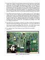
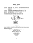
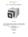
DETAILED CIRCUIT OPERATION
INTERNAL MODE GENERAL OVER-VIEW
A.) The 75211 series controller board employs modular SMT technology (see figure #1)
to provide a single board solution, employing an SCR based power amplifier to drive
permanent magnet motors.
Power Supply
A.) AC line is brought in at (J-3 and J-4) and routed through (ON:OFF) switch contacts to
power bridge consisting of (CR1,CR2,CR7,CR11).
B.) The rectified voltage at (TP #8), is dropped by series resistor (R26 or R35) and
regulated to approximately 22.7 VDC at (TP #6) by (VR4).
C.) LED connected to J5 indicates power "ON" to circuitry.
D.) Varistor RV1 and RC network R1 & C1 suppress line noise generated externally and
internally by motor and power bridge.
Output Drive
A.) Motor power bridge consists of (CR7, CR11, Q1, Q2). Diode (CR13) bypasses the
inductive current surges of the motor when the Power Bridge shuts off.
B.) Resistor capacitor combination consisting of (R5 and C2) forms a snubber network for
commutation noise suppression.
Control Section
A.) Motor speed is set by front panel pot connected to J6.
B.) A +VREF is obtained by regulating the +22VDC supply with (R34 and VR2) to
approximately +12VDC. This is routed through network (R33 and R30) to DC ground.
Adjustment pot. (R33) sets maximum motor speed approx. +10VDC at (TP-1).
C.) Components (R13, CR9, and C6) control acceleration, deceleration of motor RPM.
D.) Set-speed is controlled and regulated by differential amp (U1) and related components
(R15, C7, R17, and R2, R37, R3). All scaling is done at 5volts full-scale for all op amp
circuits. As motor load increases, back EMF, picked off drive output resistor network
(R2, R37 and R3), (TP-3) increases to 5 volts. This is fed through (R17) to pin 2 of
(U1-A) causing (TP-2) to charge integrator capacitor (C10) via (R18) to advance the
SCR firing angle, until the op amp equalizes its input voltages.
6