1
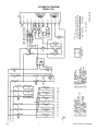
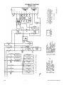
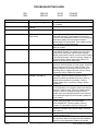
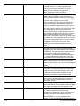
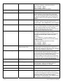
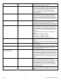
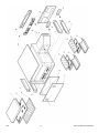
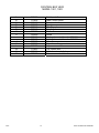
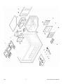
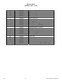
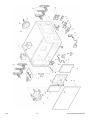
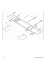
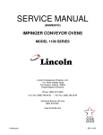
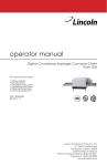
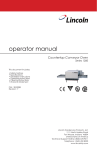
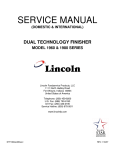
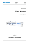
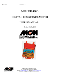
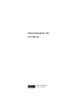
SERVICE MANUAL
DUAL TECHNOLOGY FINISHER
MODEL 1921,1922
10/03
1
DUAL TECHNOLOGY FINISHER
SEQUENCE OF OPERATION
DUAL TECHNOLOGY FINISHER
1921
1922
POWER SUPPLY
MAIN FAN CIRCUIT
TEMPERATURE CONTROL
INFRARED HEAT
CONVEYOR DRIVE
AUTOMATIC COOL DOWN
10/03
208VAC
240VAC
60 HZ.
60 HZ.
3 PHASE
3 PHASE
Electrical power to be supplied to the oven by a four conductor service for three phase.
Black conductor is hot.
Red conductor is hot.
Orange conductor is hot
Green conductor is ground.
Power is permanently supplied through the 10 amp fuses, through the normally closed
oven cavity hi-limit thermostat, to the normally open main power switch and to terminal
number 1 of the 30 minute cool down timer. Closing the main power switch enables the
30 minute cool down timer. The 30 minute cool down timer supplies line voltage to the
coil of the main fan relay, its contacts now close, supplying 208/240VAC to the main fan
motor. Voltage is also supplied to the primary of the control transformer, the conveyor
motor, the oven control and the infrared heater switch.
NOTE: Model 1922 ovens use a 240VAC to 208VAC step down transformer for the
main fan motor
Closing the main power switch supplies 208/240VAC to the primary of the control
transformer. Secondary voltage, 24VAC, is supplied to the oven control. The oven
control is set to desired temperature. The thermocouple will provide varying millivolts to
the oven control. The oven control supplies 208/240VAC to the coil of the heater relay at
intermittent intervals to maintain the desired temperature. The display on the oven
control will indicate when the main heater relay is energized.
NOTE: The display also indicates oven temperature.
Closing the infrared heater switch supplies line voltage to the coil of the infrared heater
relay, its contacts now close, supplying 208/240VAC to the infrared heaters.
Closing the main power switch supplies 208/240VAC to the primary of the control
transformer and, through the air pressure switch, the Infrared heater switch, to the
conveyor motor. Secondary voltage, 24VAC, is supplied to the oven control. Setting the
oven control to the desired time outputs voltage, through a reversing switch and
capacitor, to the conveyor motor.
NOTE: The conveyor system uses a hall effect sensor and magnet to prove operation of
the conveyor motor. If the conveyor motor is not running, “BELT JAM” is indicated on
the display.
When the machine is started, the time delay relay timing circuit is enabled, permitting
the main fan to operate for approximately 30 minutes after the machine is shut off, to
cool the machine. The 30-minute time delay relay will keep the coil of the main fan relay
energized, maintaining operation of the main fan motor for 30 minutes.
2
DUAL TECHNOLOGY FINISHER
SCHEMATIC DIAGRAM
MODEL 1921
10/03
3
DUAL TECHNOLOGY FINISHER
SCHEMATIC DIAGRAM
MODEL 1922
10/03
4
DUAL TECHNOLOGY FINISHER
TROUBLESHOOTING GUIDE
1921
1922
SYMPTOM
Oven fan will not run
208 VAC
240 VAC
POSSIBLE CAUSE
Incoming power supply
Fuses, 10 Amp, motor and
controls
Fuse holder
Hi-limit thermostat,
Oven cavity
Switch, main power
30 minute time delay relay
Relay, main fan
Transformer, Motor
(MODEL 1922 ONLY)
Circuit breaker(s), 3A.
Main fan motor
Capacitor
Oven will not heat
Main fan motor
Air pressure switch
10/03
5
60 HZ.
60 HZ.
3 PHASE
3 PHASE
EVALUATION
Check circuit breakers. Reset if required. Call power
co. if needed.
Check, replace if necessary.
Check, replace if necessary.
Terminals are normally closed. If open, reset
thermostat and retest. If thermostat will not hold for
maximum oven temperature, and oven is not exceeding
temperature setting, check for proper location of
capillary bulb in its spring holder. If the capillary checks
okay, replace the hi-limit thermostat.
Check continuity between switch terminals. Replace
switch as needed.
Check for supply voltage to 30 minute time delay relay
at terminals #1 and #6. If no voltage is present, trace
wiring back to main power switch. If there is supply
voltage at terminals #1 and #6, check for output voltage
at terminals #2 and #3. If there is incoming voltage but
no output voltage, and the main power switch is on,
replace the 30 minute time delay relay.
Check for supply voltage to relay contacts, if no voltage
is present, trace wiring back to power supply. Check for
supply voltage to the coil of the main fan relay. If no
voltage is present, trace wiring back to the 30 minute
time delay relay. If voltage is present, check to insure
contacts are closing. Replace as needed.
Check for 240 VAC supply to the transformer primary. If
no voltage is present, trace wiring back to relay. If
240VAC is present at transformer primary, check for
208VAC at the transformer secondary. If there is
primary voltage, but no secondary voltage, replace
transformer.
Push and reset circuit breakers. Check for voltage to
the circuit breaker. If no voltage is present, trace wiring
back to the main fan relay. If there is voltage present,
proceed. Check for continuity through the circuit
breaker, if the circuit breaker has been reset and there
is no continuity through the circuit breaker, replace the
circuit breaker.
Check for supply voltage at motor. If no voltage is
present, trace wiring back to circuit breakers.
WITH POWER OFF: Check for opens, shorts or
grounds. Turn fan blade to check for locked rotor.
Check for shorts or grounds.
WARNING: Capacitor has a stored charge, discharge
before testing.
Check for main fan operation. If it is not operating, refer
to “Oven fan will not run”.
This normally open switch should close when the main
fan is activated. Refer to the “Removal and installation”
section for proper adjustment. Replace as needed.
DUAL TECHNOLOGY FINISHER
Control transformer
Oven control
Thermocouple
Oven control
Thermocouple
Oven control
Main heater relay
Heating element(s)
10/03
6
Check for 208/240VAC supply to the primary of the
control transformer. If no voltage is present, trace
wiring back to the main power switch. If voltage is
present, check for 24VAC at the transformer
secondary. If there is primary voltage, but no secondary
voltage, replace the control transformer.
Check for 24VAC supply to control. If no voltage is
present, trace wiring back to control transformer. If
24VAC is present, check for a read-out on the display.
If there is 24VAC supplied, but there is no read-out on
the control display, replace the oven control.
If there is a read-out on the control, set the control to
maximum temperature (see installation operations
manual for temperature adjustment). With the control
set at maximum temperature, check for supply voltage
to the oven control at terminals J3-12 and J3-3. If there
is no voltage present, trace wiring back to the air
pressure switch. If there is voltage present, check for
output voltage at the Main heater relay (R1). If there is
voltage at the Main heater relay, proceed to “Main
heater relay” for next check. If there is no voltage at the
Main heater relay, trace wiring back to the oven control.
If there is no voltage output at the oven control, check
the read-out on the control. If the control reads
“PROBE FAIL”, this indicates that the thermocouple
has failed or become disconnected from the oven
control.
Check to be sure that the thermocouple is securely
connected to the oven control. If the thermocouple is
connected to the oven control, and the control indicates
“PROBE FAIL”, disconnect the thermocouple from the
oven control and measure the resistance of the
thermocouple. The thermocouple should read approx.
11Ω. If these readings are not achieved, replace the
thermocouple. If these readings are correct, proceed.
If the thermocouple checks good, but the oven control
display indicates that there is a thermocouple failure,
replace the oven control. If the oven control indicates a
temperature reading but the oven will not heat,
proceed.
WITH POWER ON AND THERMOCOUPLE
ATTACHED TO THE OVEN CONTROL: Measure the
DC millivolt output of the thermocouple. Refer to the
thermocouple chart (located in the “Removal” section of
the manual) for proper millivolt readings. If these
readings are not achieved, replace thermocouple.
If the thermocouple checks good, but there is no
voltage output to the Main heater relay, replace the
oven control. If there is voltage output to the Main
heater relay, proceed.
Check for supply voltage to the relay coil. If voltage is
present and the relay will not activate, replace the Main
heater relay. Also check each relay contact for high
voltage input and output.
Check the Amp draw on each power leg for proper
load. Check the specification plate for rating
information. If the amp draw is high or low, check the
individual elements for opens, shorts and proper
resistance.
WITH POWER OFF: To check resistance of the
elements, remove all leads from the elements and use
DUAL TECHNOLOGY FINISHER
No Infrared Heating
Main fan motor
Air pressure switch
Switch, Infrared heater
Infrared heater relay
Infrared Heating element(s)
Oven heats with switch off
Main heater relay or
Infrared heater relay
Intermittent heating
Thermal/overload of motor
Conveyor will not run
NOTE: Display will indicate
“Belt Jam”
Power supply
a digital multimeter.
The element resistance should be as follows:
208V – 43 ohms approx.
240V – 57 ohms approx.
Replace heating elements as needed.
Check for main fan operation. If it is not operating, refer
to “Oven fan will not run”.
Check for 208/240VAC to the air pressure switch. If no
voltage is present, trace wiring back to main power
switch. This normally open switch should close when
the main fan is activated. Refer to the “Removal and
installation” section for proper adjustment. Replace as
needed.
Check for 208/240VAC to the Infrared heater switch. If
no voltage is present, trace wiring back to the air
pressure switch. WITH POWER OFF: Check continuity
between switch terminals. Replace switch as needed.
Check for supply voltage to the relay coil. If no voltage
is present, trace wiring back to Infrared heater switch. If
voltage is present and the relay will not activate,
replace the Infrared heater relay. Also check each relay
contact for high voltage input and output.
Check the Amp draw on each power leg for proper
load. Check the specification plate for rating
information. If the amp draw is high or low, check the
individual elements for opens, shorts and proper
resistance.
WITH POWER OFF: To check resistance of the
elements, remove all leads from the elements and use
a digital multimeter.
The element resistance should be as follows:
208V – 45 ohms approx.
240V – 58 ohms approx.
Replace heating elements as needed.
The Main heater relay or Infrared heater relay has
probably failed in the closed position. If there is no
voltage to the operating coil, but there is high voltage at
the relay output, replace the heater relay.
The main fan motor is equipped with internal thermal
protection and will cease to operate if overheating
occurs. As the motor overheats and then cools, this will
cause the oven to cycle on and off intermittently.
Improper ventilation or lack of preventive maintenance
may cause this. Also, most of the problems listed under
“Oven will not heat” can cause intermittent failure.
Fuse, 10 Amp
Check circuit breakers, reset if required. Check power
plug to be sure it is firmly in receptacle. Measure
incoming power, call power co. if needed.
Check, replace if necessary.
Fuse holder
Check, replace if necessary.
Hi-limit thermostat, oven cavity Terminals are normally closed. If open, reset
thermostat and retest. If thermostat will not hold for
maximum oven temperature, and oven is not exceeding
temperature setting, check for proper location of
capillary bulb in its spring holder. If the capillary checks
okay, replace the hi-limit thermostat.
10/03
7
DUAL TECHNOLOGY FINISHER
Switch, Main Power
Control transformer
Air pressure switch
Switch, Infrared heater
Conveyor motor
Capacitor, conveyor motor
Switch, conveyor reversing
Oven control
Conveyor motor runs, but there
is no speed display
Oven control
Conveyor motor
Oven control
10/03
8
WITH POWER OFF: Check continuity between switch
terminals. Replace switch as needed.
Check for supply voltage to the primary of the control
transformer. If no voltage is present, trace wiring back
to the oven power relay. If voltage is present, check for
24 VAC at the transformer secondary. If there is
primary voltage but no secondary voltage, replace
control transformer.
Check for 208/240VAC to the air pressure switch. If no
voltage is present, trace wiring back to main power
switch. This normally open switch should close when
the main fan is activated. Refer to the “Removal and
installation” section for proper adjustment. Replace as
needed.
Check for 208/240VAC to the Infrared heater switch. If
no voltage is present, trace wiring back to the air
pressure switch. WITH POWER OFF: Check continuity
between switch terminals. Replace switch as needed.
Check for supply voltage to the conveyor motor. If no
voltage is present, trace wiring back to the primary of
the control transformer. If voltage is present and the
motor will not run, check the motor windings for opens
or shorts.
WITH POWER OFF: Check the motor windings as
follows:
Grey to black - 236 ohms approx.
Grey to brown - 236 ohms approx.
Brown to black - 472 ohms approx.
If any of the above fails, replace conveyor motor.
Check for shorts or grounds. Replace capacitor as
needed.
WARNING: Capacitor has a stored charge, discharge
before testing.
Check continuity between switch terminals. Replace
switch as needed.
If there is supply voltage to the motor, and the motor,
motor capacitor, and reversing switch check good,
replace the oven control.
Check for output voltage from oven control to hall effect
sensor (sensor is located in conveyor motor). Measure
voltage at the motor connector, red wire and yellow
wire. Voltage should be approx. 10VDC. If no voltage is
present, trace wiring back to oven control. If there is no
voltage present at the oven control, replace the oven
control.
If there is voltage supplied to the hall effect sensor,
check for a frequency output from the hall effect
sensor. Measure frequency across the yellow and white
wires at the motor connector. Frequency reading
should be approx. 25 – 100 Hz. If these readings are
not achieved, replace conveyor motor. If the readings
are achieved, proceed.
If the hall effect sensor readings are correct, but there
is no speed indicated on the display, replace the oven
control.
DUAL TECHNOLOGY FINISHER
REMOVAL, INSTALLATION AND ADJUSTMENT
DUAL TECHNOLOGY FINISHER
CAUTION!
BEFORE REMOVING OR INSTALLING ANY COMPONENT IN THE DUAL TECHNOLOGY
FINISHER, BE SURE TO DISCONNECT THE ELECTRICAL POWER SUPPLY.
MOTOR, MAIN FAN - REPLACEMENT
1.
2.
3.
4.
5.
6.
Shut off power at main breaker.
Remove conveyor and finger assemblies from oven (see installation operations
manual).
Remove front plenum assembly. Measure location of main fan on motor shaft for
reassembly. Loosen two set screws and remove main fan from motor shaft.
Remove oven top and rear cover. Disconnect wiring from motor. Remove motor and
motor mount assembly from back of oven.
Measure proper location of cooling fan on motor shaft for reassembly. Remove cooling
fan. Remove motor from motor mount.
Reassemble in reverse order and test for proper operation.
MAIN FAN - REPLACEMENT
See “MOTOR, MAIN FAN” above.
SWITCH, ON/OFF – SWITCH, STANDBY - REPLACEMENT
1.
2.
3.
4.
5.
Shut off power at main breaker.
Remove control box top.
Depress clips on sides of switch and remove switch from front panel.
Disconnect all wires from switch. Mark all wires for reinstallation.
Reassemble in reverse order and check system operation.
RELAY, TIME DELAY - REPLACEMENT
1.
2.
3.
4.
5.
Shut off power at main breaker.
Remove rear cover.
Remove wires from time delay relay and mark wires for reinstallation.
Remove mounting screw and remove time delay relay.
Reassemble in reverse order and check system operation.
RELAY, MAIN FAN - REPLACEMENT
1.
2.
3.
4.
5.
10/03
Shut off power at main breaker.
Remove rear cover.
Remove wires from main fan relay and mark wires for reassembly.
Remove mounting screws and remove main fan relay.
Reassemble in reverse order and check system operation.
9
DUAL TECHNOLOGY FINISHER
CIRCUIT BREAKER, MAIN MOTOR - REPLACEMENT
1.
2.
3.
4.
5.
Shut off power at main breaker.
Remove rear cover.
Remove wires from appropriate circuit breaker and mark wires for reassembly.
Remove mounting nut from circuit breaker and remove circuit breaker.
Reassemble in reverse order and check system operation. Be sure to reset circuit
breaker before operation.
FUSE HOLDER - REPLACEMENT
1.
2.
3.
4.
5.
Shut off power at main breaker.
Remove rear cover.
Remove wires from appropriate fuse holder and mark wires for reassembly.
Remove mounting screws from fuse holder and remove fuse holder.
Reassemble in reverse order and check system operation.
RELAY, MAIN HEATER – RELAY, INFRARED HEATER - REPLACEMENT
1.
2.
3.
4.
5.
Shut off power at main breaker.
Remove rear cover.
Remove wires from appropriate heater relay and mark wires for reassembly.
Remove mounting screws from heater relay and remove heater relay.
Reassemble in reverse order and check system operation. Be sure to mount the heater
relay in the upright position, mounting the relay upside down will cause the relay to be in
the constant “on” position.
REVERSING SWITCH, CONVEYOR - REPLACEMENT
1.
2.
3.
4.
5.
Shut off power at main breaker.
Remove rear cover.
Remove wires from reversing switch and mark wires for reassembly.
Remove mounting nut from reversing switch and remove reversing switch.
Reassemble in reverse order and check system operation.
TRANSFORMER, CONTROL - REPLACEMENT
1.
2.
3.
4.
5.
10/03
Shut off power at main breaker.
Remove rear cover.
Remove wires from control transformer and mark wires for reassembly.
Remove mounting screws and remove control transformer.
Reassemble in reverse order and check system operation.
10
DUAL TECHNOLOGY FINISHER
CAPACITOR, CONVEYOR MOTOR – REPLACEMENT
1.
2.
3.
4.
5.
6.
Shut off power at main breaker.
Remove control box top. Remove tube from air pressure switch.
Remove wiring from air pressure switch and conveyor motor capacitor and mark all
wires for reassembly.
Remove two screws and remove air pressure switch/capacitor mounting bracket.
Remove capacitor from mounting bracket.
Reassemble in reverse order and check system operation.
CONVEYOR MOTOR – REPLACEMENT
1.
2.
3.
4.
5.
6.
7.
Shut off power at main breaker.
Remove coupling from conveyor shaft (one screw at end of motor shaft).
Remove control box top and rear control box cover.
Remove three screws and remove main control board and mounting bracket.
Disconnect wiring for motor and remove motor mounting screws. Remove conveyor
motor and mounting bracket.
Remove conveyor motor from mounting bracket.
Reassemble in reverse order and check system operation.
AIR PRESSURE SWITCH – REPLACEMENT
1.
2.
3.
4.
5.
6.
Shut off power at main breaker.
Remove control box top. Remove tube from air pressure switch.
Remove wiring from air pressure switch and conveyor motor capacitor and mark all
wiring for reassembly.
Remove two screws and remove air pressure switch/capacitor mounting bracket.
Remove air pressure switch from mounting bracket.
Reassemble in reverse order and check system operation.
AIR PRESSURE SWITCH – ADJUSTMENT
1.
2.
3.
4.
Apply power to machine, set temperature control to maximum temperature.
Allow 30 minute preheat. Adjust air pressure switch so that switch will stay closed at
maximum temperature.
Remove air tube from air pressure switch and verify that switch opens.
Reconnect air tube and check system operation.
THERMOCOUPLE – REPLACEMENT
1.
2.
3.
4.
5.
6.
10/03
Shut off power at main breaker.
Remove control box top. Remove rear cover. Remove right side heating element cover.
Remove mounting screws and remove thermocouple from oven cavity.
Disconnect thermocouple from main control, remove thermocouple.
Remove connector plug from new thermocouple and mark wires for reassembly. Install
thermocouple and reassemble plug connector.
Reassemble in reverse order and check system operation.
11
DUAL TECHNOLOGY FINISHER
THERMOSTAT, HI-LIMIT – REPLACEMENT
1.
2.
3.
4.
5.
Shut off power at main breaker.
Remove rear cover, remove right side heating element cover.
Remove hi-limit thermostat from the mounting bracket. Remove mounting nut from hilimit thermostat. Remove hi-limit thermostat.
Form 90° bend in hi-limit thermostat.
Reassemble in reverse order and check system operation. Be sure to reset thermostat
before testing.
HEATING ELEMENT, MAIN – REPLACEMENT
1.
2.
3.
4.
5.
Shut off power at main breaker.
Remove conveyor, finger assemblies and plenum front. Remove rear cover and
appropriate heating element cover.
Remove wires from heating element and mark wiring for reassembly.
Remove mounting screws and remove heating element.
Reassemble in reverse order and check system operation.
HEATING ELEMENT, INFRARED – REPLACEMENT
1.
2.
3.
4.
Shut off power at main breaker.
Remove conveyor and lower finger assemblies. Remove front conveyor support from
oven cavity.
Remove front cover and heating element cover. Disconnect wiring from heating element
and mark wires for reassembly.
Reassemble in reverse order and check system operation.
MAIN CONTROL – REPLACEMENT
1.
2.
3.
4.
Shut off power at main breaker.
Remove control box top, front panel and rear control box cover.
Remove display board from front panel by pulling board off of it’s mounting pins.
Remove three screws from main control mounting bracket and remove main control board
and its mounting bracket. Remove main control from it’s mounting bracket by pulling the
control from the mounting bracket.
5. When installing new control, be sure to use ground strap so that there is no static
electricity. When installing new control, be sure to set the jumpers on the control for proper
voltage (120/240) and frequency (50Hz./60Hz.). After the new control is installed, the
control will need to be initialized. To initialize the new control, press and hold the two center
buttons on the front control panel. After the oven starts, release the buttons, the control is
now initialized. Reassemble in reverse order and check system operation.
10/03
12
DUAL TECHNOLOGY FINISHER
10/03
13
DUAL TECHNOLOGY FINISHER
GENERAL VIEW
MODEL 1921, 1922
A
B
C
D
E
F
G
H
I
J
K
L
M
N
O
P
Q
R
10/03
370438
370441
370443
370444
370445
370446
370447
370442
370439
370448
370449
370450
370451
370452
370454
370453
370455
369373
Finger housing, lower
Columnating plate, lower
Finger cover, lower left. Marked ‘LS’
Finger cover, lower right. Marked ’RS’
Front element cover
Front cover
Finger cover, upper
Columnating plate, upper
Finger housing, upper
Air wash panel, upper
Air wash panel, lower
¼ turn fastener
Air return assy.
Finger support, upper
Plenum front
Finger support, lower
Top
Receptacle, ¼ turn fastener
14
DUAL TECHNOLOGY FINISHER
10/03
15
DUAL TECHNOLOGY FINISHER
CONTROL BOX VIEW
MODEL 1921, 1922
A
B
C
D
E
F
G
H
I
J
K
L
M
N
O
10/03
369432
370456
370457
369460
369413
369410
370106
350259
370458
370460
370462
370383
369430
370463
370464
370465
Switch, on/off
Label, control panel
Front panel
Spring, compression
Drive key
Coupling sleeve
Washer
Screw
Heating element, Infrared – 208VAC
Heating element, Infrared – 240VAC
Motor, conveyor
Capacitor, conveyor motor
Air pressure switch
Top, control box
Control, main and display
Cover, rear control box
16
DUAL TECHNOLOGY FINISHER
10/03
17
DUAL TECHNOLOGY FINISHER
REAR VIEW
MODEL 1921, 1922
A
B
C
D
E
F
G
H
I
J
K
L
M
N
O
P
Q
R
S
T
U
Not shown
10/03
370466
369422
370467
370468
370469
370470
370468
370471
370472
369427
370459
370461
369479
369409
370473
357067
370359
369166
369129
12682
370474
370475
370476
Timer, cool down, 30 minute
Relay, main fan
Thermocouple
Cover, heating element
Motor mount
Motor, main fan
Cover, heating element
Cooling fan
Air switch tube assy.
Transformer, control
Heating element, 208VAC
Heating element, 240VAC
Relay, Heating element
Main fan
Circuit breaker, 3A
Thermostat, hi-limit
Reversing switch, conveyor
Fuse, 10A
Fuse holder
Adapter, cable
Power cord
Cover, rear
Transformer, motor (Model 1922 only)
18
DUAL TECHNOLOGY FINISHER
10/03
19
DUAL TECHNOLOGY FINISHER
CONVEYOR
MODEL 1921, 1922
A
B
C
D
E
F
G
H
I
J
K
Not shown
10/03
370477
370478
370440
370479
370480
370481
370482
369515
369952
370483
369471
370484
Crumb pan, right
Crumb pan, left
Frame, conveyor
Belt, conveyor
Bracket, conveyor bearing
Flanged bearing, conveyor
Shaft, idler
Drive sprocket
Connecting link, conveyor (three required)
Shaft, drive
Pin
Conveyor assembly, complete
20
DUAL TECHNOLOGY FINISHER
10/03
21
DUAL TECHNOLOGY FINISHER